1
Computer Fundamentals and Brief Information on C
CHAPTER OUTLINE
1.1 COMPONENTS OF A COMPUTER
A computer is a programmable electronic machine that accepts instructions and data through input devices, manipulates data according to instructions and provides the final result through the output device. Figure 1.1, a conventional block diagram, shows the components of a conventional computer.
Figure 1.2 shows a computer. In brief, the various blocks/components of a computer are summarized below.
Input devices: An input device feeds instructions and data, which are stored in the computer's memory. Consequently, computer reads data from the memory and manipulates it according to instructions. The various input devices to the central processor are keyboard, mouse, analog to digital converters, light pen, track ball, optical character reader, scanner, etc. Figure 1.3 shows the input devices of a computer. For example, a floppy and a compact disc can be used either as input or output device.
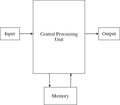
FIGURE 1.1 Block diagram of a conventional computer
Output devices: The processed data will be sent to the output device by the computer. The output device can be a monitor, printer, LED, seven-segment display, digital-to-analog converter, plotter, etc. Figure 1.4 shows the different output devices of a computer.

FIGURE 1.2 Computer as a single unit
Memory: Volatile semiconductor memory is used for storing instructions and data in the form of ones and zeros. The memory can be called as user's memory or read-write memory. The processor first reads the instructions and data then executes the instructions.
One more memory device is used in the computer which is called as ‘read only memory’(non-volatile memory), in which a program is installed permanently/fixed for providing certain operations.
Central processing unit: The heart of the computer system is a central processing unit. It comprises arithmetic and logical unit, registers and control unit. The arithmetic and logical unit performs operations based on instructions. The control unit generates the timing and control signals for carrying out the operations within the processor. The registers are used for storing the results temporarily.
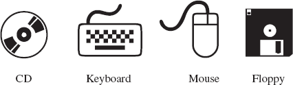
FIGURE 1.3 Input devices of a computer
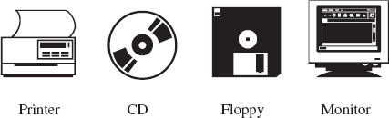
FIGURE 1.4 Output devices of a computer
1.2 LATEST COMPUTERS
Today's portable computers are just like notebooks, or even require less space than a notebook. They are handy, light weighted and portable, hence users now carry laptops while travelling for their day-to-day work.
1.3 ALGORITHM
The algorithm is defined as ‘the finite set of the steps, which provide a chain of actions for solving a definite nature of problem’. Each step in the algorithm should be well defined. Every step is known as an instruction.
1.4 SEQUENCE, SELECTION AND ITERATION
The steps/instructions of an algorithm/program can be either in sequence or out of sequence based on true or false condition or repeatedly the same set of steps/instructions are executed over a number of times. The three types of control structures are narrated as follows.
Sequence: The steps described in algorithm are performed one by one successively without skipping any step. Each instruction of such algorithm is executed, because no selection procedure or conditional branching exists in sequence algorithm.
Selection: An algorithm written in a sequence is not powerful. There must be a procedure to handle control structures such as ‘if’ or ‘if else’ in the algorithm/program.
Iteration: It is very necessary to perform the same step for a number of times. If the same statement is written repetitively, it will increase the program code. To avoid this problem, iteration mechanism is applied. The statement written in iteration block is executed for a given number of times, based on certain conditions.
1.5 FLOWCHARTS
A flowchart is an alternative technique for solving a problem. Instead of descriptive steps of algorithm, we use pictorial representation for every step. It shows a sequence of operations. A flowchart is a set of symbols, which indicates various operations in the program. For every process, there is a corresponding symbol in flowchart.
We have given below some commonly used symbols in flowcharts.
Start and stop: The start and stop symbols indicate both the beginning and the end of a flowchart. This symbol could be flat, oval or egg shaped. Figure 1.5 shows the symbol of start/stop. Usually, this symbol is used twice in a flowchart, that is at the beginning and end.
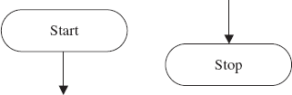
FIGURE 1.5 Start/stop symbol
Decision or test symbol: The decision symbol is diamond shaped. This symbol is used to take one of the decisions. Depending on the condition, the decision block selects one of the alternatives. In case the condition is satisfied, a set of statements will be executed, otherwise for ‘false’ the control transfers to exit.
Single alternative decision: Here, more than one flow line can be used depending upon the conduction. It is usually in the form of ‘Yes’ or ‘No’ question, with branching flow lines depending upon the answer. With single alternative, the flow diagram will be as shown in Figure 1.6.
Two alternative decisions: In Figure 1.7, two alternative paths have been shown. On satisfying the condition, statement/s pertaining to ‘action 1’ will be executed otherwise the other statement/s for ‘action 2’ will be executed.
Multiple alternative decisions: In Figure 1.8, multiple decision blocks are shown. Every decision block has two branches. In case the condition is satisfied, execution of statements of appropriate blocks takes place, otherwise next condition will be verified. If condition 1 is satisfied, then block 1 statements are executed. In the same way, other decision blocks are executed.
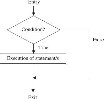
FIGURE 1.6 Single alternative decision
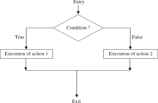
FIGURE 1.7 Two alternative decisions
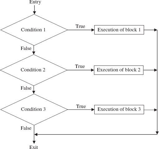
FIGURE 1.8 Multiple alternative decisions
Connector symbol: Connector symbol has to be shown in the form of a circle. It is used to establish the connection whenever it is impossible to directly join two parts in a flowchart. Quite often, the two parts of a flowchart may be on two separate pages. In such a case, connector can be used for joining the two parts. Figure 1.9 shows the connector symbol.
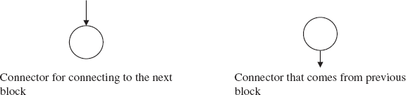
FIGURE 1.9 Connector symbol
Process symbol: A rectangle shape should show the symbol of process block. It is usually used for data handling, and values are assigned to the variables in this symbol. Figure 1.10 shows the process symbol. The operations mentioned within the rectangular block will be executed when this kind of block appears in the flowchart. There are two flow lines connected with the process symbol, one is incoming and another line is outgoing.
Loop symbol: This symbol looks like a hexagonal. It is used for the implementation of ‘for’ loops only. Four flow lines are associated with this symbol. Two lines are used to indicate the sequence of the program and the remaining two lines are used to show the looping area, i.e. from the beginning till the end.
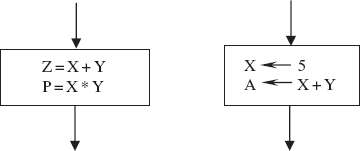
FIGURE 1.10 Process symbol
For the sake of understanding, Figure 1.11 illustrates the working of ‘for’ loop. The variable j is initialized to 0 and it is to be incremented by step 2 until it reaches the final value 10. For every increased value of j, body of the loop is executed. This process will continue until the value of j reaches 10. Here, the next block is shown for the repetitive operation.
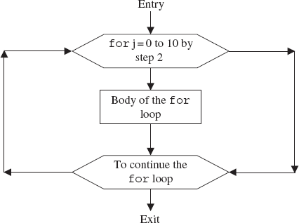
FIGURE 1.11 For loop
Input-output symbol: Input–output symbol looks like a parallelogram as shown in Figure 1.12. The input-output symbol is used to input and output the data. While the data is provided to the program for processing, then this symbol is used. There are two flow lines connected with the input–output symbol. One line comes to this symbol and another line goes from this symbol.
As shown in Figure 1.12, compiler reads the values of X and Y, and, as in the second figure, the result is either displayed on the monitor or printed using the printer.
Delay symbol: Symbol of delay is just like ‘AND’ gate. It is used for adding delay to the process. It is associated with two lines. One is incoming and the another is outgoing as shown in Figure 1.13.
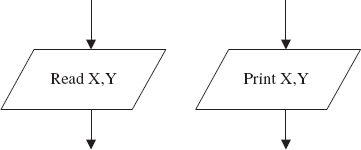
FIGURE 1.12 Input-output symbol
Manual input symbol: This is used for assigning the variable values through the keyboard, where, as in data symbol, the values are assigned directly without manual intervention. Figure 1.14 represents the symbol of manual input.
In addition, following symbols (Figure 1.15) can be used in the flowchart, and they are parts of flowcharts.
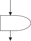
FIGURE 1.13 Delay symbol
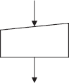
FIGURE 1.14 Manual input symbol
1.6 AN OVERVIEW OF COMPILERS AND INTERPRETERS
A program is a set of instructions for performing a particular task. A program can be written in an assembly language as well as in a high-level language. This written program is called as source program. The source program is to be transformed into the machine language which is called as object program. Either an interpreter or a compiler will do this activity. Figure 1.16 shows the process of conversion of a source program into machine program.
Interpreters: An interpreter reads only one line of a source program at a time, and converts it into object code. In case of errors, the same will be indicated instantly. The program written with an interpreter can easily be read and understood by other users as well. So security is not provided. Any one can modify the source code. Hence, it is easier than compilers. But the disadvantage is that it consumes more time for converting a source program into an object program.
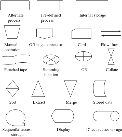
FIGURE 1.15 Some other symbols used in the flowcharts
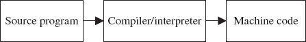
FIGURE 1.16 Translation of a source program into a machine code
Compilers: Compiler reads the entire program and converts it into object code in one stroke. Figure 1.17 shows translation of a C program into machine codes. Hence, compilers are faster than interpreters. It needs more amount of memory than interpreters do. It provides errors of not just one line, but errors of the entire program. It shows syntax and other errors in case the program is wrong. Only error free programs are executed.
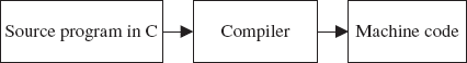
FIGURE 1.17 Translation of a C source program to machine code
The compiler creates a file that contains executable codes, and then the execution process starts. With this process of a compiler, the execution of a program will be performed with machine code.
When the program length for any application is large, compilers are preferred.
1.7 STRUCTURE OF A C PROGRAM
A C program comprises different sections which are shown in Figure 1.18.
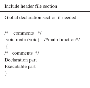
FIGURE 1.18 Various sections of a C program
- Include header file section: C program depends upon some header files for function definition that are used in a program. Each header file by default is extended with .h. The file should be included using #include directive as given below.
Example:
#include <stdio.h> or #include “stdio.h.”
In this example, <stdio.h> file is included, i.e. all the definitions and prototypes of function defined in this file are available in the current program. This file is also compiled with original program.
- Global declaration: This section declares some variables that are to be used in more than one function. These variables are known as global variables. This section must be declared outside of all the functions.
- Function main(void): Program written in C language contains a void main(void) function. Arguments, if needed, are specified within the parentheses following the function name main. Here in this program void enclosed within a bracket indicates that no arguments are passed to the main function. The keyword void before main returns nothing. If keyword int before main is observed, it indicates that function main returns integer. The function main() is a starting point of every C program. The execution of the program always begins with the function main(). Except the main() function, other sections may not be necessary. The program execution starts from the opening brace ‘{’and ends with the closing brace‘}’. Between these two braces, the programmer should declare declaration and executable parts.
- Declaration part: The declaration part declares the entire variables that are used in executable part. The initialization of variables is also done in this section. The initialization means providing initial value to the variables.
- Executable part: This part contains the statements following the declaration of the variables. It also contains a set of statements or a single statement.
- User-defined function: The functions defined by the user are called user-defined functions. These functions are generally defined after the main() function. They can also be defined before main() function. This portion is not compulsory. Programmer can follow this concept in the chapter on Functions.
- Comments: Comments are not necessary in the program. However, to understand the flow of programs, programmers can include comments in the program. They are to be inserted by the programmer, and it is useful for documentation. The clarity of the program can be followed if it is properly documented.
Comments should be placed between the delimiters /* and */. The compiler does not execute comments. Thus, we can say that comments are not the part of executable programs.
The user can frequently use any number of comments that can be placed anywhere in the program. Please note that the comment statements can be nested. The user can use the C compiler and should select the Option Menu of the editor and select the Compiler-Source-Nested Comments ON/OFF. The comments can be inserted with single statement or in nested statements in the program. Examples are as follows.
Example:
/* This is single comment */
/* This is an example of /* nested comments */*/
/* This is an example of
of comments with
multiple lines */ /* It can be nested */
1.8 C PROGRAMMING RULES
- Statements should be written in lower case letters. Upper case letters are only used for symbolic constants.
- Blank spaces may be inserted between the words. This improves the readability of the statements. However, it is not used while declaring a variable, keyword, constant and functions.
- It is not necessary to fix the position of statement in the program, i.e. the programmer can write the statement anywhere between the two braces following the declaration part. The user can also write one or more statements in one line separating them with semicolon (;). Hence, it is often called a free-form language. The following statements are valid.
a=b+c;
d=b*c;
or
a=b+c; d=b*c;
- The opening and closing braces should be balanced, i.e. if opening braces are four, then closing braces should also be four.
1.9 EXECUTING THE PROGRAM
The following steps are essential to execute a program in C.
Creation of program: The program should be written in C editor. The file name does not necessarily include extension ‘.C’. The default extension is ‘.C’. The user can also specify his/her own extension.
Compilation and linking a program: With alt-c keys, the source program statements should be translated into object program, which is suitable for execution by the computer. The translation is done after correcting each statement as per C syntax. If there is no error, compilation proceeds and translated program is stored in another file with the same file name, but with an extension ‘.obj’. If at all errors are there, the programmer should correct them. The linking is also an essential process. It puts all other program files and functions together that are required by the program. For example, if the programmer is using pow() function, then the object code of this function should be brought from math.h library of the system and linked to the main() program.
Executing the program: After the compilation, the executable object code will be loaded in the computers main memory and the program is executed. This is done with keys alt-r.
All the above steps can be performed using menu options of the editor.
1.10 AN EXAMPLE OF A C PROGRAM
Following is a sample program when executed with C compiler, the output of the program would be as follows.
“Hello! Welcome you in the C world”
void main()
{
/* First sample Program */
printf (“Hello! Welcome you in the C world”);
}
Look at the program. Execution of every C program always starts from main(). The main() is a special function designed for starting the C program.
Following the main, a pair of empty parentheses are seen. Nothing is enclosed between a pair of parentheses which indicates that no arguments to the main function.
Following the main(), program is written between opening and closing braces. Opening brace is ‘{’ and closing brace is ‘}’. Opening brace indicates that immediately following this brace the program statement should be started, and immediately after closing brace program statement ends. A function body contains all the statements within the two braces for performing a specific task. Here, in this example, our task is to print a message “Hello! Welcome you in the C world”. Two statements are written within the braces in the above program. First line is a comment line and the second line is printf() function. Within the quotation mark in the printf() function, whatever is written gets printed at the output device. Here, within the quotation mark message is “Hello! Welcome you in the C world”, and hence the same is displayed on the screen.
EXERCISES
1.A Fill in the blanks
- Computer is a _____ electronic machine.
- programmable
- non-programmable
- none of the above
- Scanner is an _____ device.
- output
- input
- input and output
- Floppy is an _____ device.
- output
- input
- input and output
- Hard disc is a _____ device.
- semiconductor
- magnetic
- conductor
- Program execution takes place in _____ memory.
- CD
- tape
- RAM
- In _____ structure, the steps described in algorithm are executed one by one without skipping any step.
- iterative
- selection
- sequential
- Program looping is done with _____ structure.
- iterative
- selection
- sequential
- Header files appear in the C program at the _____.
- beginning
- middle
- end
- Comments in C are written within _____.
- /* */
- { }
- ( )
- _____ language is CPU dependent.
- compiler
- assembler
- interpreter
- C is a _____ language.
- portable
- non-portable
- none of the above
- Opening and closing braces in C should be _____.
- unbalanced
- balanced
- uncontrolled
- _____ are pre-defined in the compiler.
- ASCII
- keywords
- none of the above
- _____ processes instructions and data.
- keys
- CPU
- hard disc
1.B True or false
- Human's intellectual capability is superior than computer's capability.
- Computers are slaves to the humans.
- Computer is a non-programmable system.
- The control unit of a CPU generates the timing and control signals.
- Palmtop is a programmable gadget.
- Algorithms are used for solving problems with a step by step procedure.
- Flowchart is a visual representation of the sequence of steps for solving a problem.
- Iteration mechanism is normally implemented in the program for avoiding repetition of similar statements in a program.
- Embedded systems are the same as that of computers.
- Compilers are slower than interpreters.
- Interpreters need more memory than the compilers.
- Embedded systems are reprogrammable systems.
- User-defined functions can be defined after and before the main() function.
- The opening and closing braces should not be balanced in C program.
- The program execution in C starts from the opening brace and ends with the closing brace.
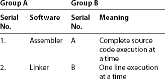
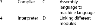
1.C Match the following correct pairs given in Group A with Group B

1.D Select the appropriate option from the multiple choices given below
- Hard disc is an
- input device
- output device
- input as well as output
- none of the above
- Mouse is an
- input device
- output device
- input as well as output
- none of the above
- Brain of the computer system is
- mouse
- printer
- keyboard
- central processing unit
- Monitor of computer system is an
- input
- output
- input as well as output
- Random access memory is
- non-volatile
- volatile
- both of the above
- ALU is a part of
- input
- output
- CPU
- Laptop device is
- non-portable
- portable
- desktop
- Which control structure is used based on condition
- sequence
- selection
- iterative
- Iterative structure means that the instructions are executed
- once
- repetitively for finite times
- infinitely
- Compiler executes at a time
- one single line
- complete source code
- two lines
- Interpreter is a
- hardware
- software
- none of the above
- C source program is in
- upper case
- lower case
- none of the above
- Keys used for compiling the source program in C
- alt-c
- alt-r
- alt-f
- Keys used for running the source program in C
- alt-c
- alt-r
- alt-f
- Keys used for closing the C editor
- alt-c
- alt-x
- alt-f
- Interpreter converts source code into
- machine code
- ASCII code
- BCD code
1.E Answer the following questions
- What is the impact of computers in our life?
- List the specifications of personal computer system consisting Pentium based CPU.
- Which technology has brought important revolution in computer networking? Explain its features.
- What are the functions of an interpreter and a compiler?
- What is the difference between an interpreter and a compiler?
- Compare and contrast between assembler and compiler.
- Describe the functions of peripheral devices of a central processing unit.
- What is meant by compilation? Explain in detail. How a compiler executes the subprograms of a program?
- Write the rules for writing a C program.
- Elaborate different sections of C program.
- Explain the functions of a linker.
- What is the role of curly braces ({ }) in C program?
- What are the user-defined functions?
- What is the role of a flowchart? Explain various symbols used in flowcharts.
- What are the benefits of algorithms? Describe the characteristics of a good algorithm.
- List the features and specifications of a laptop.
ANSWERS
1.A Fill in the blanks
- (a) programmable
- (b) input
- (c) input and output
- (b) magnetic
- (c) RAM
- (c) sequential
- (a) iterative
- (a) beginning
- (a) /* */
- (b) assembler
- (a) portable
- (b) balanced
- (b) keywords
- (b) CPU
1.B True or false
| 1. T | 2. T | 3. F | 4. T | 5. T |
| 6. T | 7. T | 8. T | 9. F | 10. F |
| 11. F | 12. F | 13. T | 14. F | 15. T |
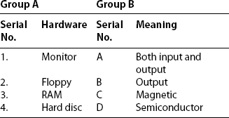
1.C Match the following correct pairs given in Group A with Group B
- 1.B, 2.A, 3.D, 4.C
- 1.B, 2.A, 3.D, 4.C
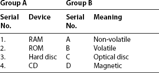
- 1.C, 2.D, 3.A, 4.B
- 1.B, 2.A, 3.D, 4.C
- 1.B, 2.C, 3.D, 4.A
1.D Select the appropriate option from the multiple choices given below
- (c) input as well as output
- (a) input device
- (d) central processing unit
- (b) output
- (b) volatile
- (c) CPU
- (b) portable
- (b) selection
- (b) repetitively for finite times
- (b) complete source code
- (b) software
- (b) lower case
- (a) alt-c
- (b) alt-r
- (b) alt-x
- (a) machine code