Chapter 1
Describe How a Network Works
The Cisco CCNA exam objectives covered in this chapter include the following:
- Describe the purpose and functions of various network devices.
- Select the components required to meet a network specification.
- Use the OSI and TCP/IP models and their associated protocols to explain how data flows in a network.
- Describe common networked applications, including web applications.
- Describe the purpose and basic operation of the protocols in the OSI and TCP models.
- Describe the impact of applications (Voice over IP and Video over IP) on a network.
- Interpret network diagrams.
- Determine the path between two hosts across a network.
- Describe the components required for network and Internet communications.
- Identify and correct common network problems at layers 1, 2, 3, and 7 using a layered model approach.
- Differentiate between LAN/WAN operation and features.
In this chapter, we will review the basics of internetworking. First, we will examine what an internetwork is; next, we will look at the Open Systems Interconnection (OSI) model and review each part. We will also review the difference between TCP and UDP with regard to VoIP and video streaming. Our review will also include PDU encapsulation, TCP/IP troubleshooting, Ethernet, and WAN connections.
Describe the Purpose and Functions of Various Network Devices
It is likely that at some point you’ll have to break up one large network into a bunch of smaller ones because user response will have dwindled to a slow crawl as the network grows and grows. With all that growth, your LAN’s traffic congestion will have reached epic proportions. The best way to handle this will be to break up your large network into several smaller networks—something called network segmentation.
You can do this by using devices like routers, switches, and bridges. Figure 1-1 displays a network that’s been segmented with a switch so each network segment connected to the switch is a separate collision domain. But make note of the fact that this network is still one broadcast domain.
Keep in mind that the hub used in Figure 1-1 just extended the one collision domain from the switch port. Here’s a list of some of the things that commonly cause LAN traffic congestion:
- Too many hosts in a broadcast domain
- Broadcast storms
- Multicasting
- Low bandwidth
- Adding hubs for connectivity to the network
Routers are used to connect networks together and route packets of data from one network to another. Cisco became the de facto standard of routers because of its high-quality router products, great selection, and fantastic service. Routers, by default, break up a broadcast domain—the set of all devices on a network segment that hear all the broadcasts sent on that segment. Figure 1-2 shows a router in a little network that creates an internetwork and breaks up broadcast domains.
Figure 1-1: A switch can replace the hub, breaking up collision domains.
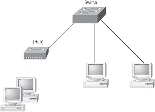
Figure 1-2: Routers create an internetwork.
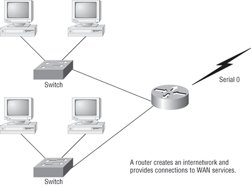
The network in Figure 1-2 shows that each host is connected to its own collision domain, and the router has created two broadcast domains—and don’t forget that the router provides connections to WAN services as well. The router uses something called a serial interface for WAN connections—specifically, a V.35 physical interface on a Cisco router.
Breaking up a broadcast domain is important because when a host or server sends a network broadcast, every device on the network must read and process that broadcast—unless you have a router. When the router’s interface receives this broadcast, it can respond by discarding the broadcast without forwarding it to other networks. Even though routers are known for breaking up broadcast domains by default, it’s important to remember that they break up collision domains as well.
Here are two advantages of using routers in your network:
- They don’t forward broadcasts by default.
- They can filter the network based on layer 3 (Network layer) information (such as an IP address).
Four router functions in your network can be listed as follows:
- Packet switching
- Packet filtering
- Internetwork communication
- Path selection
Routers are actually layer 3 switches (we’ll talk about layers later in this chapter). Unlike layer 2 switches, which forward or filter frames, routers (layer 3 switches) use logical addressing and provide what is called packet switching. When routers connect two or more networks together and use logical addressing (IP or IPv6), this is called an internetwork. Last, routers use a routing table (map of the internetwork) to make path selections and to forward packets to remote networks.
Conversely, switches don’t break up broadcast domains to create internetworks. The main purpose of a switch is to optimize a LAN’s performance and provide more bandwidth for its users. And switches don’t forward packets to other networks as routers do. Instead, they only “switch” frames from one port to another within the switched network.
By default, switches break up collision domains. This is an Ethernet term used to describe a network scenario wherein one particular device sends a packet on a network segment, forcing every other device on that same segment to pay attention to it. At the same time, a different device tries to transmit, leading to a collision, after which both devices must retransmit, one at a time, which is not very efficient. This situation is typically found in a hub environment where each host segment connects to a hub that represents only one collision domain and only one broadcast domain. By contrast, each and every port on a switch represents its own collision domain.
Switches create separate collision domains but a single broadcast domain. Routers provide a separate broadcast domain for each interface.
The term bridging was introduced before routers, switches, and hubs were implemented, so it’s pretty common to hear people referring to bridges as switches. That’s because bridges and switches basically do the same thing: they break up collision domains on a LAN. (In reality, you cannot buy a physical bridge these days; you can buy only LAN switches, but they use bridging technologies, so Cisco still calls them multiport bridges.)
A switch is basically a multiple-port bridge with greatly enhanced management capabilities and features. Also, while bridges may have up to 16 ports, switches can have hundreds!
You would use a switch/bridge in a network to reduce collisions within broadcast domains and to increase the number of collision domains in your network. Doing this provides more bandwidth for users. Keep in mind that using hubs in your network can contribute to congestion on your Ethernet network. As always, plan your network design carefully!
Exam Essentials
Understand the difference between a hub, a bridge, a switch, and a router. Hubs create one collision domain and one broadcast domain. Bridges break up collision domains but create one large broadcast domain. They use hardware addresses to filter the network. Switches are really just multiple-port bridges with more intelligence. They break up collision domains but create one large broadcast domain by default. Switches use hardware addresses to filter the network. Routers break up broadcast domains (and collision domains) and use logical addressing to filter the network.
Identify the functions and advantages of routers. Routers perform packet switching, filtering, and path selection; and they facilitate internetwork communication. One advantage of routers is that they reduce broadcast traffic.
Remember the possible causes of LAN traffic congestion. Too many hosts in a broadcast domain, broadcast storms, multicasting, and low bandwidth are all possible causes of LAN traffic congestion.
Understand the difference between a collision domain and a broadcast domain. Collision domain is an Ethernet term used to describe a network collection of devices in which one particular device sends a packet on a network segment, forcing every other device on that same segment to pay attention to it. On a broadcast domain, a set of all devices on a network segment hears all broadcasts sent on that segment.
Select the Components Required to Meet a Network Specification
As mentioned in the previous objective, routers, bridges, and switches are used in an internetwork.
Figure 1-3 shows how a network would look with all these internetwork devices in place. Remember that the router will not only break up broadcast domains for every LAN interface, but it will also break up collision domains.
Figure 1-3: Internetworking devices
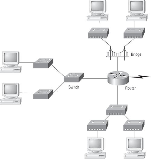
When you looked at Figure 1-3, you may have noticed that the router is at center stage and that it connects each physical network together. This type of layout is necessary because of the older technologies involved—bridges and hubs.
On the top internetwork in Figure 1-3, you’ll notice that a bridge was used to connect the hubs to a router. The bridge breaks up collision domains, but all the hosts connected to both hubs are still crammed into the same broadcast domain. Also, the bridge created only two collision domains, so each device connected to a hub is in the same collision domain as every other device connected to that same hub. This is still better than having one collision domain for all hosts.
Also, notice that the three hubs at the bottom are connected to the router, creating one collision domain and one broadcast domain. This makes the bridged network work much better.
Although bridges/switches are used to segment networks, they will not isolate broadcast or multicast packets.
In Figure 1-3, the best network connected to the router is the LAN switch network on the left. This is because each port on that switch breaks up collision domains. But it’s not all good—all devices are still in the same broadcast domain. Do you remember why this can be a really bad thing? Because all devices must listen to all broadcasts transmitted, that’s why. If your broadcast domains are too large, users have less bandwidth and are required to process more broadcasts, and network response time will slow to an unacceptable level.
Once you have only switches in your network, things change a lot! Figure 1-4 shows the network that is typically found today.
Figure 1-4: Switched networks creating an internetwork
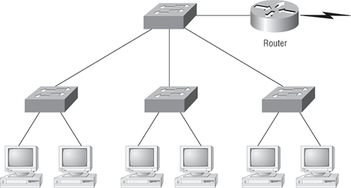
Here, the LAN switches are placed at the center of the network world so that the routers are connecting only logical networks together. If this kind of setup is implemented, virtual LANs (VLANs) are created. But it is really important to understand that even though you have a switched network, you still need a router to provide your inter-VLAN communication, or internetworking.
Obviously, the best network is one that’s correctly configured to meet the business requirements of the company it serves. LAN switches with routers, correctly placed in the network, are the best network design. This book will help you understand the basics of routers and switches, so you can make tight, informed decisions on a case-by-case basis.
Let’s go back to Figure 1-3. Looking at the figure, how many collision domains and broadcast domains are in this internetwork? Hopefully, you answered nine collision domains and three broadcast domains. The broadcast domains are definitely the easiest to see because only routers break up broadcast domains by default. Because there are three connections, that gives you three broadcast domains. The all-hub network is one collision domain; the bridge network equals three collision domains. Add in the switch network of five collision domains—one for each switch port—and you’ve got a total of nine collision domains.
So now that you’ve reviewed internetworking and the various devices in an internetwork, it’s time to head into internetworking models.
Exam Essentials
Understand which devices create a LAN and which separate and connect LANs. Switches and bridges are used to create LANs. While they do separate collision domains, they do not create separate LANs (collision domain and LAN are not the same concept). Routers are used to separate LANs and connect LANs (broadcast domains).
Understand the difference between a hub, a bridge, a switch, and a router. Hubs create one collision domain and one broadcast domain. Bridges break up collision domains but create one large broadcast domain. They use hardware addresses to filter the network. Switches are really just multiple-port bridges with more intelligence. They break up collision domains but create one large broadcast domain by default. Switches use hardware addresses to filter the network. Routers break up broadcast domains (and collision domains) and use logical addressing to filter the network.
Use the OSI and TCP/IP Models and Their Associated Protocols to Explain How Data Flows in a Network
The Department of Defense (DoD) model is basically a condensed version of the OSI model—it’s composed of the following four (instead of seven) layers:
- Process/Application layer
- Host-to-Host layer
- Internet layer
- Network Access layer
Figure 1-5 shows a comparison of the DoD model and the OSI reference model. As you can see, the two are similar in concept, but each has a different number of layers with different names.
When the different protocols in the IP stack are discussed, the layers of the OSI and DoD models are interchangeable. In other words, the Internet layer and the Network layer describe the same thing, as do the Host-to-Host layer and the Transport layer.
A vast array of protocols combine at the DoD model’s Process/Application layer to integrate the various activities and duties spanning the focus of the OSI’s corresponding top three layers (Application, Presentation, and Session). We’ll be looking closely at those protocols in the next part of this chapter. The Process/Application layer defines protocols for node-to-node application communication and controls user-interface specifications.
Figure 1-5: The DoD and OSI models

The Host-to-Host layer parallels the functions of the OSI’s Transport layer, defining protocols for setting up the level of transmission service for applications. It tackles issues such as creating reliable end-to-end communication and ensuring the error-free delivery of data. It handles packet sequencing and maintains data integrity.
The Internet layer corresponds to the OSI’s Network layer, designating the protocols relating to the logical transmission of packets over the entire network. It addresses the hosts by giving them an IP (Internet Protocol) address, and it handles the routing of packets among multiple networks.
At the bottom of the DoD model, the Network Access layer monitors the data exchange between the host and the network. The equivalent of the Data Link and Physical layers of the OSI model, the Network Access layer oversees hardware addressing and defines protocols for the physical transmission of data.
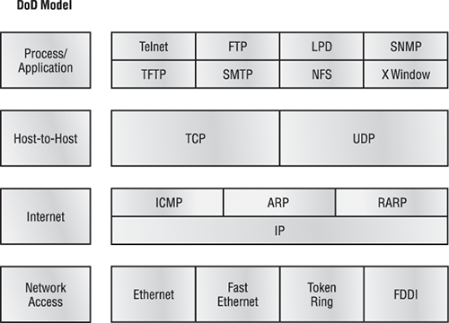
The DoD and OSI models are alike in design and concept and have similar functions in similar layers. Figure 1-6 shows the TCP/IP protocol suite and how its protocols relate to the DoD model layers.
In the following sections, we will look at the different protocols in more detail, starting with the Process/Application layer protocols.
Exam Essentials
Remember that the OSI/DoD model is a layered approach. Functions are divided into layers, and the layers are bound together. This allows layers to operate transparently to each other—that is, changes in one layer should not impact other layers.
Remember the layers of the OSI and DoD models and how they are related. The OSI was created after the DoD model and closely resembles the DoD model. The OSI Application, Presentation, and Session layers are contained in one layer of the DoD model: the Process/Application layer. The Transport layer is equivalent to the Host-to-Host layer of the DoD model, and the Network layer parallels the Internet layer.
Figure 1-6: The TCP/IP protocol suite
Describe Common Networked Applications, Including Web Applications
In this section, I’ll describe the different applications and services typically used in IP networks. The following protocols and applications are covered in this section:
- Telnet
- FTP
- TFTP
- NFS
- SMTP
- LPD
- X Window
- SNMP
- DNS
- DHCP/BootP
Telnet
Telnet is the chameleon of protocols—its specialty is terminal emulation. It allows a user on a remote client machine, called the Telnet client, to access the resources of another machine, the Telnet server. The client machine appears as though it were a dumb terminal directly attached to the local network, which allows the Telnet client to run programs on the Telnet server. This projection is actually a software image—a virtual terminal that can interact with the chosen remote host.
Users begin a Telnet session by running the Telnet client software and then logging into the Telnet server.
The problem with Telnet is that all data, even login data, is sent in cleartext. This can be a security risk. If you are having problems Telnetting into a device, you should verify that both the transmitting and receiving devices have Telnet services enabled. Lastly, by default, Cisco devices allow five simultaneous Telnet sessions.
File Transfer Protocol (FTP)
File Transfer Protocol (FTP) is the protocol that actually lets you transfer files, and it can accomplish this between any two machines using it. But FTP isn’t just a protocol; it’s also a program. Operating as a protocol, FTP is used by applications. As a program, it’s employed by users to perform file tasks by hand. FTP also allows for access to both directories and files and can accomplish certain types of directory operations, such as relocating into different ones. FTP teams up with Telnet to transparently log you in to the FTP server and then provides for the transfer of files.
Accessing a host through FTP is only the first step, though. Users must then be subjected to an authentication login that’s probably secured with passwords and usernames implemented by system administrators to restrict access. You can get around this somewhat by adopting the username anonymous—although what you’ll gain access to will be limited.
Trivial File Transfer Protocol (TFTP)
Trivial File Transfer Protocol (TFTP) is the stripped-down, stock version of FTP, but it’s the protocol of choice if you know exactly what you want and where to find it. Plus, it’s easy to use and fast! It doesn’t give you the abundance of functions that FTP does, though. TFTP has no directory-browsing abilities—it can do nothing but send and receive files. This compact little protocol also skimps in the data department, sending much smaller blocks of data than FTP sends, and there’s no authentication as with FTP, so it’s insecure. Few sites support it because of the inherent security risks.
Network File System (NFS)
Network File System (NFS) is a jewel of a protocol specializing in file sharing. It allows two different types of file systems to interoperate. It works like this: Suppose that the NFS server software is running on an NT server and the NFS client software is running on a Unix host. NFS allows for a portion of the RAM on the NT server to transparently store Unix files, which can, in turn, be used by Unix users. Even though the NT file system and Unix file system are unlike—they have different case sensitivity, filename lengths, security, and so on—both Unix users and NT users can access that same file with their normal file systems, in their normal way.
Simple Mail Transfer Protocol (SMTP)
Simple Mail Transfer Protocol (SMTP) allows us to send email and uses a spooled, or queued, method of mail delivery. Once a message has been sent to a destination, the message is spooled to a device—usually a disk. The server software at the destination regularly checks the queue for messages. When it detects them, it proceeds to deliver them to their destination. SMTP is used to send mail; POP3 is used to receive mail.
Line Printer Daemon (LPD)
The Line Printer Daemon (LPD) protocol is designed for printer sharing. The LPD, along with the Line Printer (LPR) program, allows print jobs to be spooled and sent to the network’s printers using TCP/IP.
X Window
Designed for client/server operations, X Window defines a protocol for writing client/server applications based on a graphical user interface (GUI). The idea is to allow a program, called a client, to run on one computer and have it display things through an X Window server on another computer.
Simple Network Management Protocol (SNMP)
Simple Network Management Protocol (SNMP) collects and manipulates valuable network information. It gathers data by polling the devices on the network from a management station at fixed or random intervals, requiring them to disclose certain information. When all is well, SNMP receives something called a baseline—a report delimiting the operational traits of a healthy network. This protocol can also stand as a watchdog over the network, quickly notifying managers of any sudden turn of events. These network watchdogs are called agents, and when aberrations occur, agents send an alert called a trap to the management station.
Domain Name Service (DNS)
Domain Name Service (DNS) resolves hostnames—specifically, Internet names, such as www.lammle.com. You don’t have to use DNS—you can just type in the IP address of any device with which you want to communicate. An IP address identifies hosts on a network as well as on the Internet. However, DNS was designed to make our lives easier. Think about what would happen if you wanted to move your web page to a different service provider. The IP address would change, and no one would know what the new one was. DNS allows you to use a domain name to specify an IP address. You can change the IP address as often as you want, and no one will know the difference.
DNS is used to resolve a fully qualified domain name (FQDN)—for example, www.lammle.com or todd.lammle.com. An FQDN is a hierarchy that can logically locate a system based on its domain identifier.
If you want to resolve the name todd, you either must type in the FQDN of todd.lammle.com or have a device such as a PC or router add the suffix for you. For example, on a Cisco router, you can use the command ip domain-name lammle.com to append each request with the lammle.com domain. If you don’t do that, you’ll have to type in the FQDN to get DNS to resolve the name.
Dynamic Host Configuration Protocol (DHCP)/Bootstrap Protocol (BootP)
Dynamic Host Configuration Protocol (DHCP) assigns IP addresses to hosts. It allows easier administration and works well in small to even very large network environments. All types of hardware can be used as a DHCP server, including a Cisco router.
DHCP differs from BootP in that BootP assigns an IP address to a host, but the host’s hardware address must be entered manually in a BootP table. You can think of DHCP as a dynamic BootP. But remember that BootP is also used to send an operating system from which a host can boot. DHCP can’t do that.
But there is a lot of information a DHCP server can provide to a host when the host is requesting an IP address from the DHCP server. Here’s a list of the information a DHCP server can provide:
- IP address
- Subnet mask
- Domain name
- Default gateway (routers)
- DNS server address
- WINS server address
A DHCP server can provide even more information than this, but the items in the list are the most common.
A client that sends out a DHCP Discover message in order to receive an IP address sends out a broadcast at both layer 2 and layer 3.
- The layer 2 broadcast is all Fs in hex, which looks like this: FF:FF:FF:FF:FF:FF.
- The layer 3 broadcast is 255.255.255.255, which means all networks and all hosts.
How does a router perform when it receives the broadcast mentioned previously? Although you can configure a router to forward this broadcast to a DHCP server when received, the router will discard this packet by default.
DHCP is connectionless, which means it uses User Datagram Protocol (UDP) at the Transport layer, also known as the Host-to-Host layer, which we’ll talk about next.
Figure 1-7 shows the process of a client/server relationship using a DHCP connection.
Figure 1-7: DHCP client four-step process
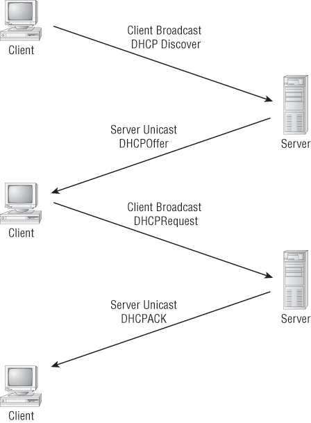
The following is the four-step process a client takes to receive an IP address from a DHCP server:
1. The DHCP client broadcasts a DHCP Discover message looking for a DHCP server (port 67).
2. The DHCP server that received the DHCP Discover message sends a unicast DHCP Offer message back to the host.
3. The client then broadcasts to the server a DHCP Request message asking for the offered IP address and possibly other information.
4. The server finalizes the exchange with a unicast DHCP Acknowledgment message.
DHCP Conflicts
A DHCP address conflict occurs when two hosts use the same IP address. This sounds bad because it is. Thankfully, the issue won’t even need to be discussed after everyone starts using IPv6.
During IP address assignment, a DHCP server checks for conflicts using the ping program to test the availability of the address before it is assigned from the pool. If no host replies, then the DHCP server assumes that the IP address is not already allocated. This helps the server know that it is providing a good address, but what about the host? To provide extra protection against the all-so-terrible IP conflict issue, the host can broadcast for its own address.
A host uses something called a gratuitous ARP to help avoid a possible duplicate address. The DHCP client sends an ARP broadcast out on the local LAN or VLAN using its newly assigned address to solve conflicts before they occur.
So, if an IP address conflict is detected, the address is removed from the DHCP pool (scope), and it is all-so-important to remember that the address will not be assigned to a host until the administrator resolves the conflict by hand.
Exam Essentials
Remember the Process/Application layer protocols. Telnet is a terminal emulation program that allows you to log in to a remote host and run programs. File Transfer Protocol (FTP) is a connection-oriented service that allows you to transfer files. Trivial FTP (TFTP) is a connectionless file transfer program. Simple Mail Transfer Protocol (SMTP) is a send-mail program.
Understand DNS and DHCP. Domain Name Service (DNS) resolves hostnames—specifically, Internet names, such as www.lammle.com. You don’t have to use DNS; you can just type in the IP address of any device with which you want to communicate. An IP address identifies hosts on a network and the Internet as well. Dynamic Host Configuration Protocol (DHCP) assigns IP addresses to hosts. It allows easier administration and works well in small to even very large network environments.
Understand DHCP conflict resolution issues. A DHCP server will use the ping program to verify that an IP address from a scope will not cause a conflict with another host. A DHCP host will use gratuitous ARP to verify that once it has an IP address from a DHCP server no other host has this address. If a conflict does occur, it is important to understand that an administrator must resolve the conflict by hand on the server.
Describe the Purpose and Basic Operation of the Protocols in the OSI and TCP Models
When networks first came into being, computers typically could communicate only with computers from the same manufacturer. For example, companies ran either a complete DECnet solution or an IBM solution—not both together. In the late 1970s, the Open Systems Interconnection (OSI) reference model was created by the International Organization for Standardization (ISO) to break this barrier.
The OSI model was meant to help vendors create interoperable network devices and software in the form of protocols so that different vendor networks could work with each other. Like world peace, it’ll probably never happen completely, but it’s still a great goal.
In the following section, I am going to explain the layered approach and how you can use this approach to help troubleshoot your internetworks.
The Layered Approach
A reference model is a conceptual blueprint of how communications should take place. It addresses all the processes required for effective communication and divides these processes into logical groupings called layers. When a communication system is designed in this manner, it’s known as layered architecture.
Software developers can use a reference model to understand computer communication processes and see what types of functions need to be accomplished on any one layer. If they are developing a protocol for a certain layer, all they need to concern themselves with is that specific layer’s functions, not those of any other layer. Another layer and protocol will handle the other functions. The technical term for this idea is binding. The communication processes that are related to each other are bound, or grouped together, at a particular layer.
Advantages of Reference Models
The OSI model is hierarchical, and the same benefits and advantages can apply to any layered model. The primary purpose of all such models, especially the OSI model, is to allow different vendors’ networks to interoperate.
Advantages of using the OSI layered model include, but are not limited to, the following:
- It divides the network communication process into smaller and simpler components, thereby aiding in component development, design, and troubleshooting.
- It allows multiple-vendor development through the standardization of network components.
- It encourages industry standardization by defining what functions occur at each layer of the model.
- It allows various types of network hardware and software to communicate.
- It prevents changes in one layer from affecting other layers, so it does not hamper development.
The OSI Reference Model
One of the greatest functions of the OSI specifications is to assist in data transfer between disparate hosts—meaning, for example, that they enable us to transfer data between a Unix host and a PC or a Mac.
The OSI isn’t a physical model, though. It’s a set of guidelines that application developers can use to create and implement applications that run on a network. It also provides a framework for creating and implementing networking standards, devices, and internetworking schemes.
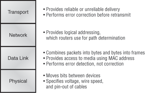
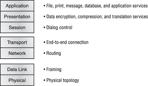
The OSI has seven different layers, divided into two groups. The top three layers define how the applications within the end stations will communicate with each other and with users. The bottom four layers define how data is transmitted from end to end. Figure 1-8 shows the three upper layers and their functions, and Figure 1-9 shows the four lower layers and their functions.
Figure 1-8: The upper layers
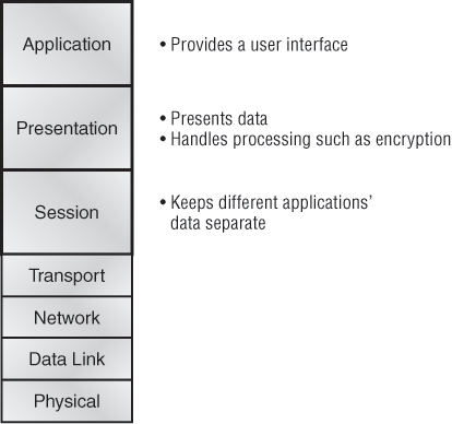
When you study Figure 1-8, understand that the user interfaces with the computer at the Application layer and also that the upper layers are responsible for applications communicating between hosts. Remember that none of the upper layers knows anything about networking or network addresses. That’s the responsibility of the four bottom layers.
In Figure 1-9, you can see that the four bottom layers are what actually define how data is transferred through a physical wire or through switches and routers. These bottom layers also determine how to rebuild a data stream from a transmitting host to a destination host’s application.
The following network devices operate at all seven layers of the OSI model:
- Network management stations (NMSs)
- Web and application servers
- Gateways (not default gateways)
- Network hosts
Basically, the ISO is pretty much the Emily Post of the network protocol world. Just as Mrs. Post wrote the book setting the standards—or protocols—for human social interaction, the ISO developed the OSI reference model as the precedent and guide for an open network protocol set. Defining the etiquette of communication models, it remains today the most popular means of comparison for protocol suites.
Figure 1-9: The lower layers
The OSI reference model has seven layers:
- Application layer (layer 7)
- Presentation layer (layer 6)
- Session layer (layer 5)
- Transport layer (layer 4)
- Network layer (layer 3)
- Data Link layer (layer 2)
- Physical layer (layer 1)
Figure 1-10 shows a summary of the functions defined at each layer of the OSI model. With this in hand, you’re ready to explore each layer’s function in detail.
In the next section, we’ll delve deeper into TCP and UDP that reside at the Transport layer.
Figure 1-10: Layer functions
Exam Essentials
Understand the advantages of using layered models. The OSI model is hierarchical, and the same benefits and advantages can apply to any layered model. The primary purpose of all such models, especially the OSI model, is to allow different vendors’ networks to interoperate. Remember that the OSI/DoD model is a layered approach.
Functions are divided into layers, and the layers are bound together. This allows layers to operate transparently to each other—that is, changes in one layer should not impact other layers.
Define the OSI layers, understand the function of each, and describe how devices and networking protocols can be mapped to each layer. You must remember the seven layers of the OSI model and what function each layer provides. The Application, Presentation, and Session layers are upper layers and are responsible for communicating from a user interface to an application. The Transport layer provides segmentation, sequencing, and virtual circuits. The Network layer provides logical network addressing and routing through an internetwork. The Data Link layer provides framing and placing data on the network medium. The Physical layer is responsible for taking 1s and 0s and encoding them into a digital signal for transmission on the network segment.
Remember the layers of the OSI model. The OSI model has seven (7) layers; starting at the top, they are as follows:
7. Application
6. Presentation
5. Session
4. Transport
3. Network
2. Data Link
1. Physical
Describe the Impact of Applications (Voice over IP and Video over IP) on a Network
The main purpose of the Host-to-Host layer is to shield the upper-layer applications from the complexities of the network. This layer says to the upper layer, “Just give me your data stream, with any instructions, and I’ll begin the process of getting your information ready to send.”
The following sections describe the two protocols at this layer:
- Transmission Control Protocol (TCP)
- User Datagram Protocol (UDP)
By understanding how TCP and UDP work, you can interpret the impact of applications on networks when using Voice and Video over IP.
Transmission Control Protocol (TCP)
Transmission Control Protocol (TCP) takes large blocks of information from an application and breaks them into segments. It numbers and sequences each segment so that the destination’s TCP stack can put the segments back into the order the application intended. After these segments are sent, TCP (on the transmitting host) waits for an acknowledgment of the receiving end’s TCP virtual circuit session, retransmitting those that aren’t acknowledged.
Before a transmitting host starts to send segments down the model, the sender’s TCP stack contacts the destination’s TCP stack to establish a connection. What is created is known as a virtual circuit. This type of communication is called connection-oriented. During this initial handshake, the two TCP layers also agree on the amount of information that’s going to be sent before the recipient’s TCP sends back an acknowledgment. With everything agreed upon in advance, the path is paved for reliable communication to take place.
TCP is a full-duplex, connection-oriented, reliable, and accurate protocol, but establishing all these terms and conditions, in addition to error checking, is no small task. TCP is very complicated and, not surprisingly, costly in terms of network overhead—and because today’s networks are much more reliable than those of yore, this added reliability is often unnecessary.
TCP Segment Format
Because the upper layers just send a data stream to the protocols in the Transport layers, I’ll demonstrate how TCP segments a data stream and prepares it for the Internet layer. When the Internet layer receives the data stream, it routes the segments as packets through an internetwork. The segments are handed to the receiving host’s Host-to-Host layer protocol, which rebuilds the data stream to hand to the upper-layer applications or protocols.
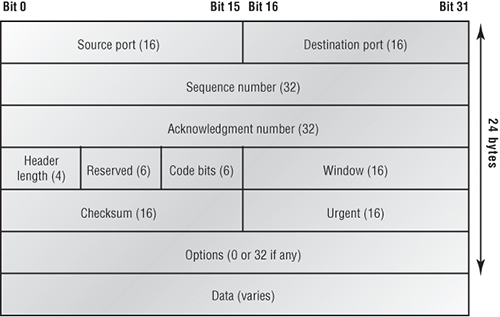
Figure 1-11 shows the TCP segment format. The figure shows the different fields within the TCP header.
The TCP header is 20 bytes long, or up to 24 bytes with options. To read more detail regarding the TCP header, please see my CCNA Cisco Certified Network Associate Study Guide, 7th Edition (Sybex, 2011).
User Datagram Protocol (UDP)
If you were to compare the User Datagram Protocol (UDP) with TCP, the former is basically the scaled-down economy model that’s sometimes referred to as a thin protocol. Like a thin person on a park bench, a thin protocol doesn’t take up a lot of room—or in this case, much bandwidth on a network.
Figure 1-11: TCP segment format
UDP doesn’t offer all the bells and whistles of TCP either, but it does do a fabulous job of transporting information that doesn’t require reliable delivery—and it does so using far fewer network resources. (UDP is covered thoroughly in Request for Comments 768.)
There are some situations in which it would definitely be wise for developers to opt for UDP rather than TCP. Remember the watchdog SNMP up there at the Process/Application layer? SNMP monitors the network, sending intermittent messages and a fairly steady flow of status updates and alerts, especially when running on a large network. The cost in overhead to establish, maintain, and close a TCP connection for each one of those little messages would reduce what would be an otherwise healthy, efficient network to a dammed-up bog in no time!
Another circumstance calling for UDP over TCP is when reliability is already handled at the Process/Application layer. Network File System (NFS) handles its own reliability issues, making the use of TCP both impractical and redundant. But ultimately, it’s up to the application developer to decide whether to use UDP or TCP, not the user who wants to transfer data faster.
UDP does not sequence the segments and does not care in which order the segments arrive at the destination. But after that, UDP sends the segments off and forgets about them. It doesn’t follow through, check up on them, or even allow for an acknowledgment of safe arrival—complete abandonment. Because of this, it’s referred to as an unreliable protocol. This does not mean that UDP is ineffective, only that it doesn’t handle issues of reliability.
Further, UDP doesn’t create a virtual circuit, nor does it contact the destination before delivering information to it. Because of this, it’s also considered a connectionless protocol. Because UDP assumes that the application will use its own reliability method, it doesn’t use any. This gives an application developer a choice when running the Internet Protocol stack: TCP for reliability or UDP for faster transfers.
So if you’re using Voice over IP (VoIP), for example, you really need to understand UDP, because if the segments arrive out of order (very common in IP networks), they’ll just be passed up to the next OSI (DoD) layer in whatever order they’re received, resulting in some seriously garbled data. On the other hand, TCP sequences the segments so they get put back together in exactly the right order—something that UDP just can’t do.
UDP Segment Format
Figure 1-12 clearly illustrates UDP’s markedly low overhead as compared to TCP’s hungry usage. Look at the figure carefully—UDP doesn’t use windowing or provide for acknowledgments in the UDP header.
Figure 1-12: The UDP segment

For a more detailed discussion on the UDP header, please see my CCNA Cisco Certified Network Associate Study Guide, 7th Edition (Sybex, 2011).
Key Concepts of Host-to-Host Protocols
Because you’ve seen both a connection-oriented (TCP) and connectionless (UDP) protocol in action, summarizing the two here would be helpful. Table 1-1 highlights some of the key concepts that you should keep in mind regarding these two protocols. You should memorize this table.
Table 1-1: Key Features of TCP and UDP
| TCP | UDP |
| Sequenced | Unsequenced |
| Reliable | Unreliable |
| Connection-oriented | Connectionless |
| Virtual circuit | Low overhead |
| Acknowledgments | No acknowledgment |
| Windowing flow control | No windowing or flow control |
Should your Voice or Video application use TCP or UDP? Because most of the applications use UDP due to time sensitivity, it is critical that you understand how to implement QoS on switch ports in order to provide priority to time sensitive data, such as voice and video. This objective wants you to simply understand the difference between TCP and UDP. It is not asking you how to configure QoS.
Exam Essentials
Remember the Host-to-Host layer protocols. Transmission Control Protocol (TCP) is a connection-oriented protocol that provides reliable network service by using acknowledgments and flow control. User Datagram Protocol (UDP) is a connectionless protocol that provides low overhead and is considered unreliable.
Remember the Internet layer protocols. Internet Protocol (IP) is a connectionless protocol that provides network address and routing through an internetwork. Address Resolution Protocol (ARP) finds a hardware address from a known IP address. Reverse ARP (RARP) finds an IP address from a known hardware address. Internet Control Message Protocol (ICMP) provides diagnostics and destination unreachable messages.
Remember the difference between connection-oriented and connectionless network services. Connection-oriented services use acknowledgments and flow control to create a reliable session. More overhead is used than in a connectionless network service. Connectionless services are used to send data with no acknowledgments or flow control. This is considered unreliable.
Remember that Voice and Video mostly use UDP. When you understand the difference between UDP and TCP, you can also understand why most application developers choose UDP: because time is of the essence, especially when connecting to phones. Plus, Cisco considers that most networks are much better today and can handle the UDP traffic better; however, you still need to implement a QoS strategy in order to achieve the desired results.
The best way to look at, build, and troubleshoot network diagrams is to use CDP. Cisco Discovery Protocol (CDP) is a proprietary protocol designed by Cisco to help administrators collect information about both locally attached and remote devices. By using CDP, you can gather hardware and protocol information about neighbor devices, which is useful info for troubleshooting and documenting the network.
In the following sections, I am going to discuss the CDP timer and CDP commands used to verify your network.
Getting CDP Timers and Holdtime Information
The show cdp command (sh cdp for short) gives you information about two CDP global parameters that can be configured on Cisco devices:
- CDP timer is how often CDP packets are transmitted out all active interfaces.
- CDP holdtime is the amount of time that the device will hold packets received from neighbor devices.
Both Cisco routers and Cisco switches use the same parameters.
For this section, I used my 2811. In the example, it will have the hostname of Corp, and it will have four serial connections to routers named R1, R2, and R3 (there are two connections to R1) and one Fast Ethernet connection to a 1242 access point with a hostname of just ap.
The output on the Corp router looks like this:
Corp#sh cdp
Global CDP information:
        Sending CDP packets every 60 seconds
        Sending a holdtime value of 180 seconds
        Sending CDPv2 advertisements is enabled
Use the global commands cdp holdtime and cdp timer to configure the CDP holdtime and timer on a router:
Corp(config)#cdp ?
  advertise-v2      CDP sends version-2 advertisements
  holdtime          Specify the holdtime (in sec) to be sent in packets
  log               Log messages generated by CDP
  run               Enable CDP
  source-interface  Insert the interface's IP in all CDP packets
  timer             Specify rate (in sec) at which CDP packets are sent  run
Corp(config)#cdp holdtime ?
  <10-255>  Length  of time (in sec) that receiver must keep this packet
Corp(config)#cdp timer ?
  <5-254>  Rate at which CDP packets are sent (in sec)
You can turn off CDP completely with the no cdp run command from the global configuration mode of a router. To turn CDP off or on for an interface, use the no cdp enable and cdp enable commands. Be patient—we’ll work through these commands shortly.
Gathering Neighbor Information
The show cdp neighbor command (sh cdp nei for short) delivers information about directly connected devices. It’s important to remember that CDP packets aren’t passed through a Cisco switch and that you see only what’s directly attached. So this means that if your router is connected to a switch, you won’t see any of the devices hooked up to that switch.
The following output shows the show cdp neighbor command used on my ISR router:
Corp#sh cdp neighbors
Capability Codes: R - Router, T - Trans Bridge, B - Source Route Bridge
                  S - Switch, H - Host, I - IGMP, r - Repeater
Device ID    Local Intrfce   Holdtme    Capability  Platform  Port ID
ap         Fas 0/1            165         T I       AIR-AP124 Fas 0
R2         Ser 0/1/0          140        R S I      2801      Ser 0/2/0
R3         Ser 0/0/1          157        R S I      1841      Ser 0/0/1
R1         Ser 0/2/0          154        R S I      1841      Ser 0/0/1
R1         Ser 0/0/0          154        R S I      1841      Ser 0/0/0
Corp#
Okay, I am displaying an output from a directly connected console cable to the Corp ISR router, and the router is directly connected to four devices. The Corp router has two connections to the R1 router. The device ID shows the configured hostname of the connected device, the local interface is our interface, and the port ID is the remote devices’ directly connected interface. All you get to view are directly connected devices.
Table 1-2 summarizes the information displayed by the show cdp neighbor command for each device.
Table 1-2: Output of the show cdp neighbor Command
| Field | Description |
| Device ID | The hostname of the device directly connected |
| Local Interface | The port or interface on which you are receiving the CDP packet |
| Holdtime | The amount of time the router will hold the information before discarding it if no more CDP packets are received |
| Capability | The capability of the neighbor, such as the router, switch, or repeater. The capability codes are listed at the top of the command output. |
| Platform | The type of Cisco device directly connected. In the previous output, a 1240AP is connected off of F0/1, a 2801 off of S0/1/0, an 1841 off of s0/0/0, another 1841 off of s0/2/0, and one last 1841 router off of s0/0/0. |
| Port ID | The neighbor device’s port or interface on which the CDP packets are multicast |
It is imperative that you have the ability to look at the output of a show cdp neighbors command and decipher the neighbor’s device (capability—i.e., router or switch), model number (platform), your port connecting to that device (local interface), and the port of the neighbor connecting to you (port ID).
Another command that’ll deliver the goods on neighbor information is the show cdp neighbors detail command (show cdp nei de for short). This command can be run on both routers and switches, and it displays detailed information about each device connected to the device on which you’re running the command. Check out this router output for an example:
Corp#sh cdp neighbors detail
-------------------------
Device ID: ap
Entry address(es): 10.1.1.2
Platform: cisco AIR-AP1242AG-A-K9 , Capabilities: Trans-Bridge IGMP
Interface: FastEthernet0/1, Port ID (outgoing port): FastEthernet0
Holdtime : 122 sec
Version :
Cisco IOS Software, C1240 Software (C1240-K9W7-M), Version 12.3(8)JEA,
    RELEASE SOFTWARE (fc2)
Technical Support: http://www.cisco.com/techsupport
Copyright (c) 1986-2006 by Cisco Systems, Inc.
Compiled Wed 23-Aug-06 16:45 by kellythw
advertisement version: 2
Duplex: full
Power drawn: 15.000 Watts
-------------------------
Device ID: R2
Entry address(es):
  IP address: 10.4.4.2
Platform: Cisco 2801, Capabilities: Router Switch IGMP
Interface: Serial0/1/0, Port ID (outgoing port): Serial0/2/0
Holdtime : 135 sec
Version :
Cisco IOS Software, 2801 Software (C2801-ADVENTERPRISEK9-M),
    Experimental Version 12.4(20050525:193634) [jezhao-ani 145]
Copyright (c) 1986-2005 by Cisco Systems, Inc.
Compiled Fri 27-May-05 23:53 by jezhao
advertisement version: 2
VTP Management Domain: ''
-------------------------
Device ID: R3
Entry address(es):
  IP address: 10.5.5.1
Platform: Cisco 1841, Capabilities: Router Switch IGMP
Interface: Serial0/0/1, Port ID (outgoing port): Serial0/0/1
Holdtime : 152 sec
Version :
Cisco IOS Software, 1841 Software (C1841-IPBASE-M), Version 12.4(1c),
    RELEASE SOFTWARE (fc1)
Technical Support: http://www.cisco.com/techsupport
Copyright (c) 1986-2005 by Cisco Systems, Inc.
Compiled Tue 25-Oct-05 17:10 by evmiller
advertisement version: 2
VTP Management Domain: ''
-------------------------
[output cut]
Corp#
First, the hostnames and IP addresses of all directly connected devices are displayed. In addition to the same information displayed by the show cdp neighbor command (see Table 1-2), the show cdp neighbor detail command displays the IOS version of the neighbor device.
Remember that you can see only the IP addresses of directly connected devices.
The show cdp entry * command displays the same information as the show cdp neighbor details command. Here’s an example of the router output using the show cdp entry * command:
Corp#sh cdp entry *
-------------------------
Device ID: ap
Entry address(es):
Platform: cisco AIR-AP1242AG-A-K9 , Capabilities: Trans-Bridge IGMP
Interface: FastEthernet0/1, Port ID (outgoing port): FastEthernet0
Holdtime : 160 sec
Version :
Cisco IOS Software, C1240 Software (C1240-K9W7-M), Version 12.3(8)JEA,
    RELEASE SOFTWARE (fc2)
Technical Support: http://www.cisco.com/techsupport
Copyright (c) 1986-2006 by Cisco Systems, Inc.
Compiled Wed 23-Aug-06 16:45 by kellythw
advertisement version: 2
Duplex: full
Power drawn: 15.000 Watts
-------------------------
Device ID: R2
Entry address(es):
  IP address: 10.4.4.2
Platform: Cisco 2801, Capabilities: Router Switch IGMP
 --More--
[output cut]
Although the show cdp neighbors detail and show cdp entry * commands are very similar, the show cdp entry * command allows you to display only one line of output for each directly connected neighbor, whereas the show cdp neighbor detail command does not.
Documenting a Network Topology Using CDP
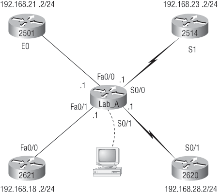
As the title of this section implies, I’m going to show you how to document a sample network by using CDP. You’ll learn to determine the appropriate router types, interface types, and IP addresses of various interfaces using only CDP commands and the show running-config command. You can only console into the Lab_A router to document the network. You’ll have to assign any remote routers the next IP address in each range. You can use Figure 1-13 to complete the documentation.
In this output, you can see that you have a router with four interfaces: two FastEthernet and two Serial. First, determine the IP addresses of each interface by using the show running-config command:
Lab_A#sh running-config
Building configuration...
Current configuration : 960 bytes
!
version 12.2
service timestamps debug uptime
service timestamps log uptime
no service password-encryption
!
hostname Lab_A
!
ip subnet-zero
!
!
interface FastEthernet0/0
 ip address 192.168.21.1 255.255.255.0
 duplex auto
!
interface FastEthernet0/1
 ip address 192.168.18.1 255.255.255.0
 duplex auto
!
interface Serial0/0
ip address 192.168.23.1 255.255.255.0
!
interface Serial0/1
ip address 192.168.28.1 255.255.255.0
!
ip classless
!
line con 0
line aux 0
line vty 0 4
!
end
Now that this step is completed, you can write down the IP addresses of the Lab_A router’s four interfaces. Next, you need to determine the type of device on the other end of each of these interfaces. It’s easy to do this—just use the show cdp neighbors command:
  Lab_A#sh cdp neighbors
  Capability Codes: R - Router, T - Trans Bridge, B - Source Route Bridge
  S - Switch, H - Host, I - IGMP, r - Repeater
  Device ID   Local Intrfce     Holdtme    Capability Platform  Port ID
  Lab_B        Fas 0/0            178          R        2501     E0
  Lab_C        Fas 0/1            137          R        2621     Fa0/0
  Lab_D        Ser 0/0            178          R        2514     S1
  Lab_E        Ser 0/1            137          R        2620     S0/1
  Lab_A#
Figure 1-13: Documenting a network topology using CDP
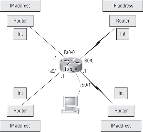
You’ve got a good deal of information now. By using both the show running-config and show cdp neighbors commands, you know about all the IP addresses of the Lab_A router, plus the types of routers connected to each of the Lab_A router’s links, and all the interfaces of the remote routers.
By using all the information gathered from show running-config and show cdp neighbors, you can create the topology in Figure 1-14.
If you needed to, you also could’ve used the show cdp neighbors detail command to view the neighbor’s IP addresses. But because you know the IP addresses of each link on the Lab_A router, you already know what the next available IP address is going to be.
Exam Essentials
Understand when to use CDP. Cisco Discovery Protocol can be used to help you document as well as troubleshoot your network.
Remember what the output from the various show cdp neighbors commands provides. The show cdp neighbors command provides the following information: device ID, local interface, holdtime, capability, platform, and port ID (remote interface). The show cdp neighbors detail and show cdp entry * commands provide everything the show cdp neighbors provides, plus the IP address of each directly connected neighbor and the IOS version.
Figure 1-14: Network topology documented
Determine the Path between Two Hosts across a Network
Once you create an internetwork by connecting your WANs and LANs to a router, you’ll need to configure logical network addresses, such as IP addresses, to all hosts on the internetwork so that they can communicate across that internetwork.
The term routing is used for taking a packet from one device and sending it through the network to another device on a different network. Routers don’t really care about hosts—they only care about networks and the best path to each network. The logical network address of the destination host is used to get packets to a network through a routed network, and then the hardware address of the host is used to deliver the packet from a router to the correct destination host.
If your network has no routers, then it should be apparent that you are not routing. Routers route traffic to all the networks in your internetwork. To be able to route packets, a router must know, at a minimum, the following:
- Destination address
- Neighbor routers from which it can learn about remote networks
- Possible routes to all remote networks
- The best route to each remote network
- How to maintain and verify routing information
The router learns about remote networks from neighbor routers or from an administrator. The router then builds a routing table (a map of the internetwork) that describes how to find the remote networks. If a network is directly connected, then the router already knows how to get to it.
If a network isn’t directly connected to the router, the router must use one of two ways to learn how to get to the remote network: static routing, meaning that someone must hand-type all network locations into the routing table, or something called dynamic routing. In dynamic routing, a protocol on one router communicates with the same protocol running on neighbor routers. The routers then update each other about all the networks they know about and place this information into the routing table. If a change occurs in the network, the dynamic routing protocols automatically inform all routers about the event. If static routing is used, the administrator is responsible for updating all changes by hand into all routers. Typically, in a large network, a combination of both dynamic and static routing is used.
Before we jump into the IP routing process, let’s take a look at a simple example that demonstrates how a router uses the routing table to route packets out of an interface. We’ll be going into a more detailed study of the process in the next section.
Figure 1-15 shows a simple two-router network. Lab_A has one serial interface and three LAN interfaces.
Figure 1-15: A simple routing example
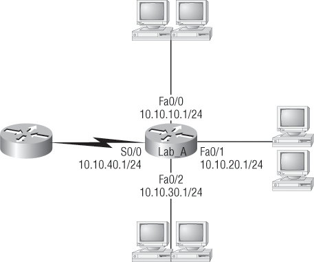
By looking at Figure 1-15, you can see which interface Lab_A will use to forward an IP datagram to a host with an IP address of 10.10.10.10.
By using the command show ip route, you can see the routing table (map of the internetwork) that Lab_A uses to make forwarding decisions:
Lab_A#sh ip route
[output cut]
Gateway of last resort is not set
C      10.10.10.0/24 is directly connected, FastEthernet0/0
C      10.10.20.0/24 is directly connected, FastEthernet0/1
C      10.10.30.0/24 is directly connected, FastEthernet0/2
C      10.10.40.0/24 is directly connected, Serial 0/0
The C in the routing table output means that the networks listed are “directly connected,” and until you add a routing protocol—something like RIP, EIGRP, or the like—to the routers in your internetwork (or use static routes), you’ll have only directly connected networks in your routing table.
RIP and EIGRP are routing protocols and are covered in Chapters 8 and 9 of my CCNA Cisco Certified Network Associate Study Guide, 7th Edition (Sybex, 2011).
So let’s get back to the original question: By looking at the figure and the output of the routing table, can you tell what IP will do with a received packet that has a destination IP address of 10.10.10.10? The router will packet-switch the packet to interface FastEthernet 0/0, and this interface will frame the packet and then send it out on the network segment.
Based on the output of the next routing table, which interface will a packet with a destination address of 10.10.10.14 be forwarded from?
Lab_A#sh ip route
[output cut]
Gateway of last resort is not set
C      10.10.10.16/28 is directly connected, FastEthernet0/0
C      10.10.10.8/29 is directly connected, FastEthernet0/1
C      10.10.10.4/30 is directly connected, FastEthernet0/2
C      10.10.10.0/30 is directly connected, Serial 0/0
First, you can see that the network is subnetted and each interface has a different mask. If you can’t subnet, you just can’t answer this question. The address 10.10.10.14 would be a host in the 10.10.10.8/29 subnet connected to the FastEthernet0/1 interface. If you don’t understand or are struggling, just go back and reread Chapter 4 of the CCNA Cisco Certified Network Associate Study Guide, 7th Edition—this should make perfect sense to you afterward.
You really need to make sure you understand IP routing because it’s super-important. This section is going to test your understanding of the IP routing process by having you look at a figure and answer a very basic IP routing question.
Figure 1-16 shows a LAN connected to RouterA, which is, in turn, connected via a WAN link to RouterB. RouterB has a LAN connected with an HTTP server attached. How does a frame from HostA get to the HTTP server?
Figure 1-16: IP routing example
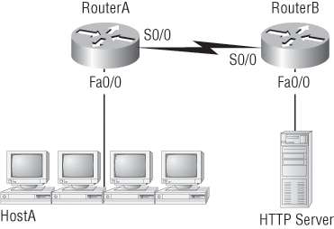
The critical information you need to glean from this figure is exactly how IP routing will occur in this example.
1. The destination address of a frame, from HostA, will be the MAC address of the F0/0 interface of the RouterA router.
2. The destination address of a packet will be the IP address of the network interface card (NIC) of the HTTP server.
3. The destination port number in the segment header will have a value of 80.
That example was a pretty simple one, and it was also to the point. One thing to remember is that if multiple hosts are communicating to the server using HTTP, they must all use a different source port number. That is how the server keeps the data separated at the Transport layer.
Exam Essentials
Understand the basic IP routing process. You need to remember that the frame changes at each hop but that the packet is never changed or manipulated in any way until it reaches the destination device.
Understand that MAC addresses are always local. A MAC (hardware) address will only be used on a local LAN. It will never pass a router’s interface.
Understand that a frame carries a packet to only two places. A frame uses MAC (hardware) addresses to send a packet on a LAN. The frame will take the packet to either a host on the LAN or a router’s interface if the packet is destined for a remote network.
Describe the Components Required for Network and Internet Communications
When a host transmits data across a network to another device, the data goes through encapsulation: It is wrapped with protocol information at each layer of the OSI model. Each layer communicates only with its peer layer on the receiving device.
To communicate and exchange information, each layer uses Protocol Data Units (PDUs). These units hold the control information attached to the data at each layer of the model. They are usually attached to the header in front of the data field, but they can also be in the trailer, or end, of it.
Each PDU attaches to the data by encapsulating it at each layer of the OSI model, and each has a specific name, depending on the information provided in each header. This PDU information is read only by the peer layer on the receiving device. After it’s read, it’s stripped off and the data is then handed to the next layer up.
Figure 1-17 shows the PDUs and how they attach control information to each layer. This figure demonstrates how the upper-layer user data is converted for transmission on the network. The data stream is then handed down to the Transport layer, which sets up a virtual circuit to the receiving device by sending over a sync packet. Next, the data stream is broken into smaller pieces, and a Transport layer header (a PDU) is created and attached to the header of the data field; now the piece of data is called a segment. Each segment is sequenced so the data stream can be put back together on the receiving side exactly as it was transmitted.
Figure 1-17: Data encapsulation
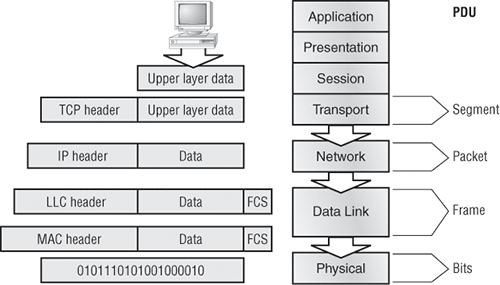
Each segment is then handed to the Network layer for network addressing and routing through the internetwork. Logical addressing (for example, IP) is used to get each segment to the correct network. The Network layer protocol adds a control header to the segment handed down from the Transport layer, creating what is called a packet or datagram. Remember that the Transport and Network layers work together to rebuild a data stream on a receiving host, but it’s not part of their work to place their PDUs on a local network segment—which is the only way to get the information to a router or host.
The Data Link layer is responsible for taking packets from the Network layer and placing them on the network medium (cable or wireless). The Data Link layer encapsulates each packet in a frame, and the frame’s header carries the hardware address of the source and destination hosts. If the destination device is on a remote network, then the frame is sent to a router to be routed through an internetwork. Once it gets to the destination network, a new frame is used to get the packet to the destination host.
To put this frame on the network, it must first be put into a digital signal. Because a frame is really a logical group of 1s and 0s, the Physical layer is responsible for encoding these digits into a digital signal, which is read by devices on the same local network. The receiving devices will synchronize on the digital signal and extract (decode) the 1s and 0s from the digital signal. At this point, the devices build the frames, run a CRC, and then check their answer against the answer in the frame’s FCS field. If it matches, the packet is pulled from the frame and what’s left of the frame is discarded. This process is called de-encapsulation. The packet is handed to the Network layer, where the address is checked. If the address matches, the segment is pulled from the packet and what’s left of the packet is discarded. The segment is processed at the Transport layer, which rebuilds the data stream and acknowledges to the transmitting station that it received each piece. It then happily hands the data stream to the upper-layer application.
At a transmitting device, the data encapsulation method works like this:
1. User information is converted to data for transmission on the network.
2. Data is converted to segments and a reliable connection is set up between the transmitting and receiving hosts.
3. Segments are converted to packets or datagrams, and a logical address is placed in the header so each packet can be routed through an internetwork.
4. Packets or datagrams are converted to frames for transmission on the local network. Hardware (Ethernet) addresses are used to uniquely identify hosts on a local network segment.
5. Frames are converted to bits, and a digital encoding and clocking scheme is used.
Figure 1-18 illustrates these concepts in more detail, using the layer addressing.
Remember that a data stream is handed down from the upper layer to the Transport layer. As technicians, we really don’t care who generates the data stream because that’s really a programmer’s problem. Our job is to rebuild the data stream reliably and hand it to the upper layers on the receiving device.
Before discussing Figure 1-18 any further, let’s discuss port numbers and make sure you understand them. The Transport layer uses port numbers to define both the virtual circuit and the upper-layer process, as you can see from Figure 1-19.
Figure 1-18: PDU and layer addressing
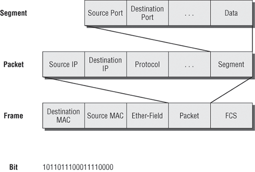
Figure 1-19: Port numbers at the Transport layer
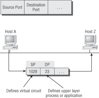
The Transport layer takes the data stream, makes segments out of it, and establishes a reliable session by creating a virtual circuit. It then sequences (numbers) each segment and uses acknowledgments and flow control. If you’re using TCP, the virtual circuit is defined by the source port number. Remember, the host just makes this up starting at port number 1024 (0 through 1023 are reserved for well-known port numbers). The destination port number defines the upper-layer process (application) that the data stream is handed to when the data stream is reliably rebuilt on the receiving host.
Now that you understand port numbers and how they are used at the Transport layer, let’s go back to Figure 1-18. Once the Transport layer header information is added to the piece of data, it becomes a segment and is handed down to the Network layer along with the destination IP address. (The destination IP address was handed down from the upper layers to the Transport layer with the data stream, and it was discovered through a name-resolution method at the upper layers—probably DNS.)
The Network layer adds a header and adds the logical addressing (IP addresses) to the front of each segment. Once the header is added to the segment, the PDU is called a packet. The packet has a protocol field that describes where the segment came from (either UDP or TCP) so it can hand the segment to the correct protocol at the Transport layer when it reaches the receiving host.
The Network layer is responsible for finding the destination hardware address that dictates where the packet should be sent on the local network. It does this by using the Address Resolution Protocol (ARP). IP at the Network layer looks at the destination IP address and compares that address to its own source IP address and subnet mask. If it turns out to be a local network request, the hardware address of the local host is requested via an ARP request. If the packet is destined for a remote host, IP will look for the IP address of the default gateway (router) instead.
The packet, along with the destination hardware address of either the local host or default gateway, is then handed down to the Data Link layer. The Data Link layer will add a header to the front of the packet and the piece of data then becomes a frame. (It is called a frame because both a header and a trailer are added to the packet, which makes the data resemble bookends or a frame, if you will.) This is shown in Figure 1-19. The frame uses an Ether-Type field to describe which protocol the packet came from at the Network layer. Now a CRC is run on the frame, and the answer to the CRC is placed in the FCS field found in the trailer of the frame.
The frame is now ready to be handed down, one bit at a time, to the Physical layer, which will use bit timing rules to encode the data in a digital signal. Every device on the network segment will synchronize itself with the clock and extract the 1s and 0s from the digital signal and build a frame. After the frame is rebuilt, a CRC is run to make sure that the frame is okay. If everything turns out to be all good, the hosts will check the destination address to see if the frame is for them.
Exam Essentials
Remember the steps of the encapsulation method. The encapsulation method is data, segment, packet, frames, and bits.
Remember the Transport port numbers that are reserved. Hosts can create a session to another host by using any number from 1024 to 65535. Ports 0 through 1023 are well known port numbers and are reserved.
Identify and Correct Common Network Problems at Layers 1, 2, 3, and 7 Using a Layered Model Approach
Troubleshooting IP addressing is obviously an important skill because running into trouble somewhere along the way is pretty much a sure thing—and it’s going to happen to you. Because of this nasty fact, it will be great when you can save the day because you can figure out (diagnose) the problem and fix it on an IP network whether you’re at work or at home!
This is where I’m going to show you the “Cisco way” of troubleshooting IP addressing. Let’s go over the troubleshooting steps that Cisco uses first. These steps are pretty simple, but they are important nonetheless. Pretend that you’re at a customer host, and they’re complaining that their host cannot communicate with a server, which just happens to be on a remote network. Here are the four troubleshooting steps that Cisco recommends:
1. Open a DOS window and ping 127.0.0.1. This is the diagnostic or loopback address, and if you get a successful ping, your IP stack is then considered to be initialized. If it fails, then you have an IP stack failure and need to reinstall TCP/IP on the host.
2. From the DOS window, ping the IP address of the local host. If that’s successful, then your network interface card (NIC) is functioning. If it fails, then there is a problem with the NIC card. Success does not mean that a cable is plugged into the NIC, only that the IP protocol stack on the host can communicate with the NIC.
3. From the DOS window, ping the default gateway (router). If the ping works, it means that the NIC is plugged into the network and can communicate on the local network. It also means the default router is responding and configured with the proper IP address on its local interface. If it fails, then you have a local physical network problem that could be happening anywhere from the NIC to the router.
4. If steps 1 through 3 were successful, try to ping the remote server. If that works, then you know that you have IP communication between the local host and the remote server. You also know that the remote physical network is working.
If the user still can’t communicate with the server after steps 1 through 4 are successful, then you probably have some type of name resolution problem and need to check your Domain Name Service (DNS) settings. But if the ping to the remote server fails, then you know you have some type of remote physical network problem and need to go to the server and work through steps 1 through 3 until you find the snag.
Once you’ve gone through all these steps, what do you do if you find a problem? How do you go about fixing an IP address configuration error? Let’s move on and discuss how to determine the IP address problems and how to fix them.
Let’s use Figure 1-20 as an example of your basic IP trouble—poor Sally can’t log in to the Windows server. You could call the Microsoft team to tell them their server is a pile of junk that’s causing all of your problems, but that is probably not such a great idea. First, you should double-check your network instead.
Figure 1-20: Basic IP troubleshooting
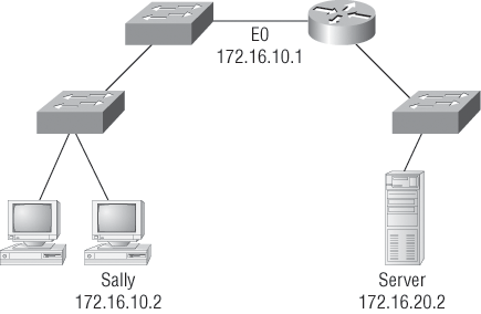
Okay, let’s get started by going over the troubleshooting steps that Cisco follows. They’re pretty simple, but important nonetheless. Pretend that you’re with a customer and they’re complaining that their host can’t communicate with a server that just happens to be on a remote network. Here are the four troubleshooting steps Cisco recommends:
1. Open a DOS window and ping 127.0.0.1. This is the diagnostic, or loopback, address, and if you get a successful ping, your IP stack is considered to be initialized. If it fails, then you have an IP stack failure and need to reinstall TCP/IP on the host.
C:>ping 127.0.0.1
Pinging 127.0.0.1 with 32 bytes of data:
Reply from 127.0.0.1: bytes=32 time<1ms TTL=128
Reply from 127.0.0.1: bytes=32 time<1ms TTL=128
Reply from 127.0.0.1: bytes=32 time<1ms TTL=128
Reply from 127.0.0.1: bytes=32 time<1ms TTL=128
Ping statistics for 127.0.0.1:
    Packets: Sent = 4, Received = 4, Lost = 0 (0% loss),
Approximate round trip times in milli-seconds:
    Minimum = 0ms, Maximum = 0ms, Average = 0ms
2. From the DOS window, ping the IP address of the local host. If that’s successful, your NIC is functioning. If it fails, there is a problem with the NIC. Success here doesn’t mean that a cable is plugged into the NIC, only that the IP protocol stack on the host can communicate to the NIC (via the LAN driver).
C:>ping 172.16.10.2
Pinging 172.16.10.2 with 32 bytes of data:
Reply from 172.16.10.2: bytes=32 time<1ms TTL=128
Reply from 172.16.10.2: bytes=32 time<1ms TTL=128
Reply from 172.16.10.2: bytes=32 time<1ms TTL=128
Reply from 172.16.10.2: bytes=32 time<1ms TTL=128
Ping statistics for 172.16.10.2:
    Packets: Sent = 4, Received = 4, Lost = 0 (0% loss),
Approximate round trip times in milli-seconds:
    Minimum = 0ms, Maximum = 0ms, Average = 0ms
3. From the DOS window, ping the default gateway (router). If the ping works, it means that the NIC is plugged into the network and can communicate on the local network. If it fails, you have a local physical network problem that could be anywhere from the NIC to the router.
C:>ping 172.16.10.1
Pinging 172.16.10.1 with 32 bytes of data:
Reply from 172.16.10.1: bytes=32 time<1ms TTL=128
Reply from 172.16.10.1: bytes=32 time<1ms TTL=128
Reply from 172.16.10.1: bytes=32 time<1ms TTL=128
Reply from 172.16.10.1: bytes=32 time<1ms TTL=128
Ping statistics for 172.16.10.1:
    Packets: Sent = 4, Received = 4, Lost = 0 (0% loss),
Approximate round trip times in milli-seconds:
    Minimum = 0ms, Maximum = 0ms, Average = 0ms
4. If steps 1 through 3 were successful, try to ping the remote server. If that works, then you know that you have IP communication between the local host and the remote server. You also know that the remote physical network is working.
C:>ping 172.16.20.2
Pinging 172.16.20.2 with 32 bytes of data:
Reply from 172.16.20.2: bytes=32 time<1ms TTL=128
Reply from 172.16.20.2: bytes=32 time<1ms TTL=128
Reply from 172.16.20.2: bytes=32 time<1ms TTL=128
Reply from 172.16.20.2: bytes=32 time<1ms TTL=128
Ping statistics for 172.16.20.2:
    Packets: Sent = 4, Received = 4, Lost = 0 (0% loss),
Approximate round trip times in milli-seconds:
    Minimum = 0ms, Maximum = 0ms, Average = 0ms
If the user still can’t communicate with the server after steps 1 through 4 are successful, you probably have some type of name resolution problem and need to check your DNS settings. But if the ping to the remote server fails, then you know you have some type of remote physical network problem and need to go to the server and work through steps 1 through 3 until you find the snag.
Before we move on to determining IP address problems and how to fix them, let’s review some basic DOS commands that you can use to help troubleshoot your network from both a PC and a Cisco router (the commands might do the same thing, but they are implemented differently).
Packet InterNet Groper (ping) Uses ICMP echo request and replies to test if a node IP stack is initialized and alive on the network.
traceroute Displays the list of routers on a path to a network destination by using TTL time-outs and ICMP error messages. This command will not work from a DOS prompt.
tracert Same command as traceroute, but it’s a Microsoft Windows command and will not work on a Cisco router.
arp -a Displays IP-to-MAC address mappings on a Windows PC.
show ip arp Same command as arp -a, but displays the ARP table on a Cisco router. Like the commands traceroute and tracert, they are not interchangeable between DOS and Cisco.
ipconfig /all Used only from a DOS prompt, shows you the PC network configuration.
For more details about troubleshooting IP address problems, see the CCNA Cisco Certified Network Associate Study Guide, 7th Edition (Sybex, 2011).
Exam Essentials
Remember how to test your local stack. You can ping 127.0.0.1 to test that the IP protocol is initialized on your system.
Understand how to test IP on your local host. To verify that IP is communicating on your host, you need to ping your IP address. Open a DOS prompt and use the ipconfig command to find your IP address. This will verify that your host is communicating from IP to your LAN driver.
Understand how to verify that your host is communicating on the local network. The best way to verify that your host is communicating on the local network is to ping your default gateway.
Differentiate between LAN/WAN Operation and Features
Layer 2 switching is considered hardware-based bridging because it uses specialized hardware called an application-specific integrated circuit (ASIC). ASICs can run up to gigabit speeds with very low latency rates.
Latency is the time measured from when a frame enters a port to the time it exits a port.
Bridges and switches read each frame as it passes through the network. The layer 2 device then puts the source hardware address in a filter table and keeps track of the port on which the frame was received. This information (logged in the bridge’s or switch’s filter table) is what helps the machine determine the location of the specific sending device. Figure 1-21 shows a switch in an internetwork.
Figure 1-21: A switch in an internetwork
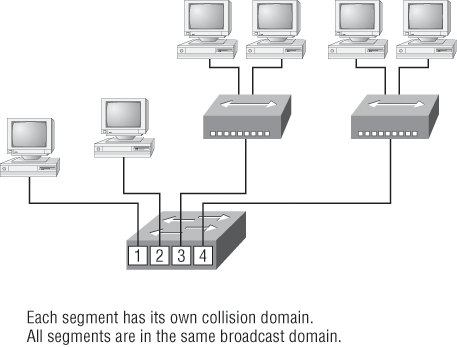
The real estate business is all about location, location, location, and it’s the same for both layer 2 and layer 3 devices. Although both need to be able to negotiate the network, it’s crucial to remember that they’re concerned with very different parts of it. Primarily, layer 3 machines (such as routers) need to locate specific networks, whereas layer 2 machines (switches and bridges) need to eventually locate specific devices. So, networks are to routers as individual devices are to switches and bridges. And routing tables that “map” the internetwork are for routers as filter tables that “map” individual devices are for switches and bridges.
After a filter table is built on the layer 2 device, it will forward frames only to the segment where the destination hardware address is located. If the destination device is on the same segment as the frame, the layer 2 device will block the frame from going to any other segments. If the destination is on a different segment, the frame can be transmitted only to that segment. This is called transparent bridging.
When a switch interface receives a frame with a destination hardware address that isn’t found in the device’s filter table, it will forward the frame to all connected segments except for the source port. If the unknown device that was sent the “mystery frame” replies to this forwarding action, the switch updates its filter table regarding that device’s location. But in the event the destination address of the transmitting frame is a broadcast address, the switch will forward all broadcasts to every connected segment by default.
All devices that the broadcast is forwarded to are considered to be in the same broadcast domain. This can be a problem; layer 2 devices propagate layer 2 broadcast storms that choke performance, and the only way to stop a broadcast storm from propagating through an internetwork is with a layer 3 device—a router.
The biggest benefit of using switches instead of hubs in your internetwork is that each switch port is actually its own collision domain. (Conversely, a hub creates one large collision domain.) But even armed with a switch, you still can’t break up broadcast domains. Neither switches nor bridges will do that. They’ll typically simply forward all broadcasts instead.
Another benefit of LAN switching over hub-centered implementations is that each device on every segment plugged into a switch can transmit simultaneously—at least, they can as long as there is only one host on each port and a hub isn’t plugged into a switch port. As you might have guessed, hubs allow only one device per network segment to communicate at a time.
Ethernet Networking
Ethernet is a contention-based media access method that allows all hosts on a network to share the same bandwidth of a link. Ethernet is popular because it’s readily scalable, meaning that it’s comparatively easy to integrate new technologies, such as upgrading from Fast Ethernet to Gigabit Ethernet, into an existing network infrastructure. It’s also relatively simple to implement in the first place, and with it, troubleshooting is reasonably straightforward. Ethernet uses both Data Link and Physical layer specifications, and this chapter will give you both the Data Link layer and Physical layer information you need to effectively implement, troubleshoot, and maintain an Ethernet network.
Collision Domain
As mentioned in earlier in this chapter, the term collision domain is an Ethernet term that refers to a particular network scenario wherein one device sends a packet out on a network segment, thereby forcing every other device on that same physical network segment to pay attention to it. This can be bad because if two devices on one physical segment transmit at the same time, a collision event—a situation where each device’s digital signals interfere with another on the wire—occurs and forces the devices to retransmit later. Collisions can have a dramatically negative effect on network performance, so they’re definitely something you want to avoid.
This type of situation is typically found in a hub environment where each host segment connects to a hub that represents only one collision domain and one broadcast domain. This begs a question that was discussed earlier: What’s a broadcast domain?
Broadcast Domain
Here’s the written definition: a broadcast domain refers to a group of devices on a network segment that hear all the broadcasts sent on that network segment.
Even though a broadcast domain is typically a boundary delimited by physical media like switches and routers, it can also reference a logical division of a network segment where all hosts can reach each other via a Data Link layer (hardware address) broadcast.
That’s the basic story, so now let’s take a look at a collision detection mechanism used in half-duplex Ethernet.
CSMA/CD
Ethernet networking uses Carrier Sense Multiple Access with Collision Detection (CSMA/CD), a protocol that helps devices share the bandwidth evenly without having two devices transmit at the same time on the network medium. CSMA/CD was created to overcome the problem of those collisions that occur when packets are transmitted simultaneously from different nodes. And trust me—good collision management is crucial, because when a node transmits in a CSMA/CD network, all the other nodes on the network receive and examine that transmission. Only bridges and routers can effectively prevent a transmission from propagating throughout the entire network.
So, how does the CSMA/CD protocol work? Let’s start by taking a look at Figure 1-22.
Figure 1-22: CSMA/CD
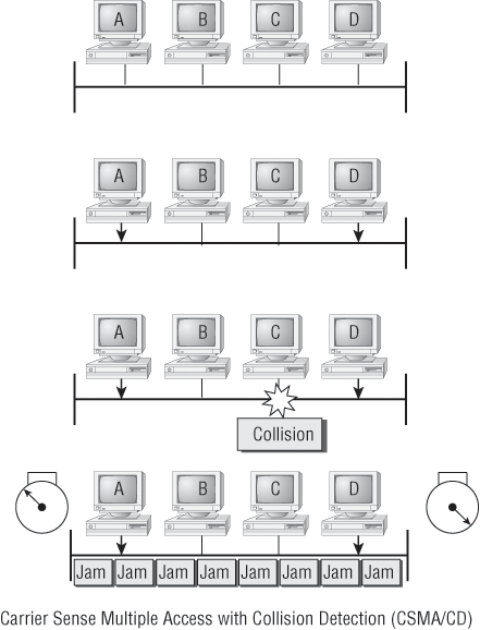
When a host wants to transmit over the network, it first checks for the presence of a digital signal on the wire. If all is clear (no other host is transmitting), the host will then proceed with its transmission. But it doesn’t stop there. The transmitting host constantly monitors the wire to make sure that no other hosts begin transmitting. If the host detects another signal on the wire, it sends out an extended jam signal that causes all nodes on the segment to stop sending data (think busy signal). The nodes respond to that jam signal by waiting a while before attempting to transmit again. Backoff algorithms determine when the colliding stations can retransmit. If collisions keep occurring after 15 tries, the nodes attempting to transmit will then time out.
In the following sections, I am going to cover Ethernet in detail at both the Data Link layer (layer 2) and the Physical layer (layer 1).
Half-Duplex and Full-Duplex Ethernet
Half-duplex Ethernet is defined in the original 802.3 Ethernet; Cisco says it uses only one wire pair with a digital signal running in both directions on the wire. Certainly, the IEEE specifications discuss the process of half-duplex somewhat differently, but what Cisco is talking about is a general sense of what is happening here with Ethernet.
It also uses the CSMA/CD protocol to help prevent collisions and to permit retransmitting if a collision does occur. If a hub is attached to a switch, it must operate in half-duplex mode because the end stations must be able to detect collisions. Half-duplex Ethernet—typically 10BaseT—is only about 30 to 40 percent efficient as Cisco sees it because a large 10BaseT network will usually only give you 3 to 4Mbps, at most.
But full-duplex Ethernet uses two pairs of wires instead of one wire pair like half-duplex. And full-duplex uses a point-to-point connection between the transmitter of the transmitting device and the receiver of the receiving device. This means that with full-duplex data transfer, you get a faster data transfer than with half-duplex. And because the transmitted data is sent on a different set of wires than the received data, no collisions will occur.
The reason that you don’t need to worry about collisions is because now it’s like there is a freeway with multiple lanes instead of the single-lane road provided by half-duplex. Full-duplex Ethernet is supposed to offer 100 percent efficiency in both directions—for example, you can get 20Mbps with a 10Mbps Ethernet running full-duplex or 200Mbps for Fast Ethernet. But this rate is something known as an aggregate rate, which translates as “you’re supposed to get” 100 percent efficiency. There are no guarantees in networking, as in life.
Full-duplex Ethernet can be used in five situations:
- With a connection from a switch to a host
- With a connection from a switch to a switch
- With a connection from a host to a host
- With a connection from a switch to a router
- With a connection from a router to a router
Full-duplex Ethernet requires a point-to-point connection when only two nodes are present. You can run full-duplex with just about any device except a hub.
Now, if it’s capable of all that speed, why wouldn’t it deliver? Well, when a full-duplex Ethernet port is powered on, it first connects to the remote end and then negotiates with the other end of the Fast Ethernet link. This is called an auto-detect mechanism. This mechanism first decides on the exchange capability, which means that it checks to see if it can run at 10 or 100Mbps. It then checks to see if it can run full-duplex, and if it can’t, it will run half-duplex.
Remember that half-duplex Ethernet shares a collision domain and provides a lower effective throughput than full-duplex Ethernet, which typically has a private collision domain and a higher effective throughput.
Last, remember these important points:
- There are no collisions in full-duplex mode.
- A dedicated switch port is required for each full-duplex node.
- The host network card and the switch port must be capable of operating in full-duplex mode.
Ethernet at the Data Link Layer
Ethernet at the Data Link layer is responsible for Ethernet addressing, commonly referred to as hardware addressing or MAC addressing. Ethernet is also responsible for framing packets received from the Network layer and preparing them for transmission on the local network through the Ethernet contention-based media access method.
Ethernet Addressing
Here’s where we get into how Ethernet addressing works. It uses the Media Access Control (MAC) address burned into each and every Ethernet network interface card (NIC). The MAC, or hardware, address is a 48-bit (6-byte) address written in a hexadecimal format.
Figure 1-23 shows the 48-bit MAC addresses and how the bits are divided.
Figure 1-23: Ethernet addressing using MAC addresses

The organizationally unique identifier (OUI) is assigned by the IEEE to an organization. It’s composed of 24 bits, or 3 bytes. The organization, in turn, assigns a globally administered address (24 bits, or 3 bytes) that is unique (supposedly, again—no guarantees) to each and every adapter it manufactures. Look closely at the figure. The high-order bit is the Individual/Group (I/G) bit. When it has a value of 0, you can assume that the address is the MAC address of a device and may well appear in the source portion of the MAC header. When it is a 1, you can assume that the address represents either a broadcast or multicast address in Ethernet or a broadcast or functional address in Token Ring and FDDI.
The next bit is the global/local bit, or just G/L bit (also known as U/L, where U means universal). When set to 0, this bit represents a globally administered address (as by the IEEE). When the bit is a 1, it represents a locally governed and administered address. The low-order 24 bits of an Ethernet address represent a locally administered or manufacturer-assigned code. This portion commonly starts with 24 0s for the first card made and continues in order until there are 24 1s for the last (16,777,216th) card made. You’ll find that many manufacturers use these same six hex digits as the last six characters of their serial number on the same card.
Defining WAN Terms
Before you run out and order a WAN service type from a provider, it would be a really good idea to understand the following terms that service providers typically use:
Customer premises equipment (CPE) Customer premises equipment (CPE) is equipment that’s owned by the subscriber and located on the subscriber’s premises.
Demarcation point The demarcation point is the precise spot where the service provider’s responsibility ends and the CPE begins. It’s generally a device in a telecommunications closet owned and installed by the telecommunications company (telco). It’s your responsibility to cable (extended demarc) from this box to the CPE, which is usually a connection to a CSU/DSU or ISDN interface.
Local loop The local loop connects the demarc to the closest switching office, which is called a central office.
Central office (CO) This point connects the customer’s network to the provider’s switching network. Good to know is that a central office (CO) is sometimes referred to as a point of presence (POP).
Toll network The toll network is a trunk line inside a WAN provider’s network. This network is a collection of switches and facilities owned by the ISP.
Definitely familiarize yourself with these terms because they’re crucial to understanding WAN technologies.
WAN Connection Types
As you’re probably aware, a WAN can use a number of different connection types, and I’m going to introduce you to each of the various types of WAN connections you’ll find on the market today. Figure 1-24 shows the different WAN connection types that can be used to connect your LANs together (DTE) over a DCE network.
Figure 1-24: WAN connection types
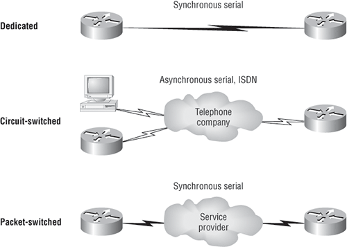
Here’s a list explaining the different WAN connection types:
Leased Lines These are usually referred to as a point-to-point or dedicated connection. A leased line is a preestablished WAN communications path that goes from the CPE through the DCE switch, then over to the CPE of the remote site. The CPE enables DTE networks to communicate at any time with no cumbersome setup procedures to muddle through before transmitting data. When you’ve got plenty of cash, this is really the way to go because it uses synchronous serial lines up to 45Mbps. HDLC and PPP encapsulations are frequently used on leased lines. We’ll go over them in detail in a bit.
Circuit Switching When you hear the term circuit switching, think phone call. The big advantage is cost—you only pay for the time you actually use. No data can transfer before an end-to-end connection is established. Circuit switching uses dial-up modems or ISDN and is used for low-bandwidth data transfers. You’re probably thinking, “Modems? Did he say modems? Aren’t those only in museums by now?” After all, with all the wireless technologies available, who would use a modem these days? Well, some people do have ISDN, and it still is viable (and I do suppose someone does use a modem now and then), but circuit switching can be used in some of the newer WAN technologies as well.
Packet Switching This is a WAN switching method that allows you to share bandwidth with other companies to save money. Packet switching can be thought of as a network that’s designed to look like a leased line yet charges you more like circuit switching. But lower cost isn’t always better—there’s definitely a downside: If you need to transfer data constantly, just forget about this option. Instead, get yourself a leased line. Packet switching will work for you only if your data transfers are the bursty type—not continuous. Frame Relay and X.25 are packet-switching technologies with speeds that can range from 56Kbps up to T3 (45Mbps).
MultiProtocol Label Switching (MPLS) uses a combination of both circuit switching and packet switching, but it’s out of this book’s scope. Even so, after you pass your CCNA exam, it would be well worth your time to look into MPLS, so I’ll briefly talk about MPLS shortly.
WAN Support
Basically, Cisco supports only HDLC, PPP, and Frame Relay on its serial interfaces, and you can see this with the encapsulation ? command from any serial interface (your output may vary depending on the IOS version you are running):
Corp#config t
Corp(config)#int s0/0/0
Corp(config-if)#encapsulation ?
  atm-dxi      ATM-DXI encapsulation
  frame-relay  Frame Relay networks
  hdlc         Serial HDLC synchronous
  lapb         LAPB (X.25 Level 2)
  ppp          Point-to-Point protocol
  smds         Switched Megabit Data Service (SMDS)
  x25          X.25
If I had other types of interfaces on my router, I would have other encapsulation options, such as ISDN or ADSL. And remember, you can’t configure Ethernet or Token Ring encapsulation on a serial interface.
Next, I’m going to define the most prominently known WAN protocols used today: Frame Relay, ISDN, LAPB, LAPD, HDLC, PPP, PPPoE, Cable, DSL, MPLS, and ATM. Just so you know, the only WAN protocols you’ll usually find configured on a serial interface are HDLC, PPP, and Frame Relay—but who said we’re stuck with using only serial interfaces for wide area connections?
Frame Relay A packet-switched technology that made its debut in the early 1990s, Frame Relay is a high-performance Data Link and Physical layer specification. It’s pretty much a successor to X.25, except that much of the technology in X.25 used to compensate for physical errors (noisy lines) has been eliminated. An upside to Frame Relay is that it can be more cost effective than point-to-point links, plus it typically runs at speeds of 64Kbps up to 45Mbps (T3). Another Frame Relay benefit is that it provides features for dynamic bandwidth allocation and congestion control.
ISDN Integrated Services Digital Network (ISDN) is a set of digital services that transmits voice and data over existing phone lines. ISDN offers a cost-effective solution for remote users who need a higher-speed connection than analog dial-up links can give them, and it’s also a good choice to use as a backup link for other types of links like Frame Relay or T1 connections.
LAPB Link Access Procedure, Balanced (LAPB) was created to be a connection-oriented protocol at the Data Link layer for use with X.25, but it can also be used as a simple data link transport. A not-so-good characteristic of LAPB is that it tends to create a tremendous amount of overhead due to its strict time-out and windowing techniques.
LAPD Link Access Procedure, D-Channel (LAPD) is used with ISDN at the Data Link layer (layer 2) as a protocol for the D (signaling) channel. LAPD was derived from the Link Access Procedure, Balanced (LAPB) protocol and is designed primarily to satisfy the signaling requirements of ISDN basic access.
HDLC High-Level Data-Link Control (HDLC) was derived from Synchronous Data Link Control (SDLC), which was created by IBM as a Data Link connection protocol. HDLC works at the Data Link layer and creates very little overhead compared to LAPB.
It wasn’t intended to encapsulate multiple Network layer protocols across the same link—the HDLC header doesn’t contain any identification about the type of protocol being carried inside the HDLC encapsulation. Because of this, each vendor that uses HDLC has its own way of identifying the Network layer protocol, meaning each vendor’s HDLC is proprietary with regard to its specific equipment.
PPP Point-to-Point Protocol (PPP) is a pretty famous, industry-standard protocol. Because all multiprotocol versions of HDLC are proprietary, PPP can be used to create point-to-point links between different vendors’ equipment. It uses a Network Control Protocol field in the Data Link header to identify the Network layer protocol and allows authentication and multilink connections to be run over asynchronous and synchronous links.
PPPoE Point-to-Point Protocol over Ethernet encapsulates PPP frames in Ethernet frames and is usually used in conjunction with ADSL services. It gives you a lot of the familiar PPP features such as authentication, encryption, and compression, but there’s a downside—it has a lower maximum transmission unit (MTU) than standard Ethernet does, and if your firewall isn’t solidly configured, this little attribute can really give you some grief.
Still somewhat popular in the United States, the main feature of PPPoE is that it adds a direct connection to Ethernet interfaces while providing DSL support as well. It’s often used by many hosts on a shared Ethernet interface for opening PPP sessions to various destinations via at least one bridging modem.
In a modern HFC network, typically 500 to 2,000 active data subscribers are connected to a certain cable network segment, all sharing the upstream and downstream bandwidth. (Hybrid fibre-coaxial, or HFC, is a telecommunications industry term for a network that incorporates both optical fiber and coaxial cable to create a broadband network.) The actual bandwidth for Internet service over a cable TV (CATV) line can be up to about 27Mbps on the download path to the subscriber, with about 2.5Mbps of bandwidth on the upload path. Typically, users get an access speed from 256Kbps to 6Mbps. This data rate varies greatly throughout the United States.
DSL Digital Subscriber Line is a technology used by traditional telephone companies to deliver advanced services (high-speed data and sometimes video) over twisted-pair copper telephone wires. It typically has lower data-carrying capacity than HFC networks, and data speeds can be range limited by line lengths and quality. Digital subscriber line is not a complete end-to-end solution but rather a Physical layer transmission technology like dial-up, cable, or wireless. DSL connections are deployed in the last mile of a local telephone network—the local loop. The connection is set up between a pair of modems on either end of a copper wire that is run between the CPE and the Digital Subscriber Line Access Multiplexer (DSLAM). A DSLAM is the device located at the provider’s CO and concentrates connections from multiple DSL subscribers.
MPLS MultiProtocol Label Switching (MPLS) is a data-carrying mechanism that emulates some properties of a circuit-switched network over a packet-switched network. MPLS is a switching mechanism that imposes labels (numbers) on packets and then uses those labels to forward packets. The labels are assigned on the edge of the MPLS of the network, and forwarding inside the MPLS network is done solely based on labels. Labels usually correspond to a path to layer 3 destination addresses (equal to IP destination-based routing). MPLS was designed to support forwarding of protocols other than TCP/IP. Because of this, label switching within the network is performed the same regardless of the layer 3 protocol. In larger networks, the result of MPLS labeling is that only the edge routers perform a routing lookup. All the core routers forward packets based on the labels, which makes forwarding the packets through the service provider network faster. (Most companies are replacing their Frame Relay networks with MPLS today).
ATM Asynchronous Transfer Mode (ATM) was created for time-sensitive traffic, providing simultaneous transmission of voice, video, and data. ATM uses cells that are a fixed 53 bytes long instead of packets. It also can use isochronous clocking (external clocking) to help the data move faster. Typically, if you are running Frame Relay today, you will be running Frame Relay over ATM.
Exam Essentials
Understand half-duplex technology. Half-duplex only uses one wire pair at a time to both transmit and receive. Hubs can run only half-duplex.
Understand full-duplex technology. Full-duplex devices use both wire pairs, so they can both transmit and receive at the same time. Hubs cannot run full-duplex. You must have a switch to run full-duplex on your PC.
Describe the operation of Carrier Sense Multiple Access with Collision Detection (CSMA/CD). CSMA/CD is a protocol that helps devices share the bandwidth evenly without having two devices transmit at the same time on the network medium. Although it does not eliminate collisions, it helps to greatly reduce them, which reduces retransmissions, resulting in a more efficient transmission of data for all devices.
Know the differences between leased lines, circuit switching, and packet switching. A leased line is a dedicated connection, a circuit-switched connection is like a phone call and can be on or off, and packet switching is essentially a connection that looks like a leased line but is priced more like a circuit-switched connection.
Understand the different WAN protocols. Pay particular attention to HDLC, Frame Relay, and PPP. HDLC is the default encapsulation on Cisco routers. PPP provides an industry-standard way of encapsulating multiple routed protocols across a link and must be used when connecting equipment from multiple vendors. Frame relay is a packet-switched technology that can offer cost advantages over leased lines but has more complex configuration options.
1. How does a router respond when an interface receives a broadcast?
A. The router forwards the broadcast out all ports.
B. The router reads the data and responds accordingly to the request.
C. The router discards the broadcast.
D. The router forwards it to only the Ethernet LANs.
2. You want to implement a mechanism that automates the IP configuration, including IP address, subnet mask, default gateway, and DNS information. Which protocol will you use to accomplish this?
A. SMTP
B. SNMP
C. DHCP
D. ARP
3. What does a DHCP host use to verify that a duplicate IP address has not been received by the DHCP server?
A. Ping
B. ARP
C. Gratuitous ping
D. RARP
E. Gratuitous ARP
4. Which of the following describe the DHCP Discover message? (Choose two.)
A. It uses FF:FF:FF:FF:FF:FF as a layer 2 broadcast.
B. It uses UDP as the Transport layer protocol.
C. It uses TCP as the Transport layer protocol.
D. It does not use a layer 2 destination address.
5. What are two characteristics of Telnet? (Choose two.)
A. It sends data in cleartext format.
B. It is a protocol designed and used only by Cisco routers.
C. It is more secure than using Secure Shell (SSH).
D. You must purchase Telnet from Microsoft.
E. It requires that the destination device be configured to support Telnet services and connections.
6. If you are running a VoIP application and a UDP segment is received out of order, what does IP do with this segment?
A. Rejects the packet
B. Accepts the packet and hands it up to the next layer in the order it was received
C. Accepts the packet and hands it up to the next layer in the order it was supposed to be received
D. Broadcasts the packet
7. Which of the following are TCP/IP protocols used at the Application layer of the OSI model? (Choose three.)
A. IP
B. TCP
C. Telnet
D. FTP
E. TFTP
8. When data is encapsulated, which is the correct order?
A. Data, frame, packet, segment, bit
B. Segment, data, packet, frame, bit
C. Data, segment, packet, frame, bit
D. Data, segment, frame, packet, bit
9. Which two statements about a reliable connection-oriented data transfer are true?
A. Receiving hosts acknowledge receipt of data.
B. When buffers are full, packets are discarded and are not retransmitted.
C. Windowing is used to provide flow control and unacknowledged data segments.
D. If the transmitting host’s timer expires before receipt of an acknowledgment, the transmitting host drops the virtual circuit.
10. Which of the following describe router functions? (Choose four.)
A. Packet switching
B. Collision prevention
C. Packet filtering
D. Broadcast domain enlargement
E. Internetwork communication
F. Broadcast forwarding
G. Path selection
1. C. Routers will discard any broadcast by default, unless configured to forward to a specific destination.
2. C. Dynamic Host Configuration Protocol (DHCP) is used to provide IP information to hosts on your network. DHCP can provide a lot of information, but the most common is IP address, subnet mask, default gateway, and DNS information.
3. E. To verify that a DHCP host has not received a duplicate IP address from a DHCP server, the host will send out an ARP request using its own IP address; this is called a gratuitous ARP.
4. A, B. A client that sends out a DHCP Discover message in order to receive an IP address sends out a broadcast at both layer 2 and layer 3. The layer 2 broadcast is all Fs in hex, or FF:FF:FF:FF:FF:FF. The layer 3 broadcast is 255.255.255.255, which means all networks and all hosts. DHCP is connectionless, which means it uses User Datagram Protocol (UDP) at the Transport layer, also called the Host-to-Host layer.
5. A, E. Telnet has been around as long as networking, and there is no cost to implement Telnet services on your network. However, all data is sent in a cleartext format and both the sending and receiving devices must have Telnet services running.
6. B. UDP does not have sequencing, so it will hand the segment up in the order it was received.
7. C, D, E. Telnet, File Transfer Protocol (FTP), and Trivial FTP (TFTP) are all Application layer protocols. IP is a Network layer protocol. Transmission Control Protocol (TCP) is a Transport layer protocol.
8. C. The encapsulation method is data, segment, packet, frame, bit.
9. A, C. When a virtual circuit is created, windowing is used for flow control and acknowledgment of data.
10. A, C, E, G. Routers provide packet switching, packet filtering, internetwork communication, and path selection.
