One of the most common WAN protocols used today is Frame Relay. This appendix provides an overview of Frame Relay, its components, and its implementations. It also details how to configure a Cisco router to simulate a Frame Relay switch.
Frame Relay is a high-performance WAN protocol that operates at the physical and data link layers of the OSI reference model. Frame Relay originally was designed for use across Integrated Services Digital Network (ISDN) interfaces. Today it is used over a variety of other network interfaces as well. This section focuses on Frame Relay's specifications and applications in the context of WAN services.
Frame Relay is an example of a packet-switched technology. Packet-switched networks enable end stations to dynamically share the network medium and the available bandwidth. Variable-length packets are used for more efficient and flexible transfers. These packets then are switched among the various network segments until the destination is reached. Statistical multiplexing techniques control network access in a packet-switched network. The advantage of this technique is that it accommodates more flexibility and more efficient use of bandwidth. Most of today's popular LANs, such as Ethernet and Token Ring, are packet-switched networks.
Frame Relay often is described as a streamlined version of X.25, offering fewer of the robust capabilities, such as windowing and retransmission of lost data, which are offered in X.25. This is because Frame Relay typically operates over WAN facilities that offer more reliable connection services and a higher degree of reliability than the facilities available during the late 1970s and early 1980s that served as the common platforms for X.25 WANs. As mentioned earlier, Frame Relay is strictly a Layer 2 protocol suite, whereas X.25 provides services at Layer 3 (the network layer) as well. This enables Frame Relay to offer higher performance and greater transmission efficiency than X.25, and it makes Frame Relay suitable for current WAN applications, such as LAN interconnection.
Initial proposals for the standardization of Frame Relay were presented to the Consultative Committee on International Telephone and Telegraph (CCITT) in 1984. Because of a lack of interoperability and lack of complete standardization, however, Frame Relay did not experience significant deployment during the late 1980s.
A major development in Frame Relay's history occurred in 1990 when Cisco Systems, Digital Equipment, Northern Telecom, and StrataCom formed a consortium to focus on Frame Relay technology development. This consortium developed a specification that conformed to the basic Frame Relay protocol that was being discussed in CCITT, but it extended the protocol with features that provide additional capabilities for complex internetworking environments. These Frame Relay extensions are referred to collectively as the Local Management Interface (LMI).
Since the consortium's specification was developed and published, many vendors have announced their support of this extended Frame Relay definition. ANSI and CCITT subsequently have standardized their own variations of the original LMI specification, and these standardized specifications now are more commonly used than the original version.
Internationally, Frame Relay was standardized by the International Telecommunications Union-Telecommunications Sector (ITU-T). In the United States, Frame Relay is an American National Standards Institute (ANSI) standard.
Devices attached to a Frame Relay WAN fall into two general categories: data terminal equipment (DTE) and data circuit-terminating equipment (DCE). DTEs generally are considered to be terminating equipment for a specific network and typically are located on the premises of a customer. In fact, the customer can own them. Examples of DTE devices are terminals, personal computers, routers, and bridges.
DCEs are carrier-owned internetworking devices. The purpose of DCE equipment is to provide clocking and switching services in a network, which are the devices that actually transmit data through the WAN. In most cases, these are packet switches. Figure B-1 shows the relationship between the two categories of devices.
The connection between a DTE device and a DCE device consists of both a physical layer component and a data link layer component. The physical component defines the mechanical, electrical, functional, and procedural specifications for the connection between the devices. One of the most commonly used physical layer interface specifications is the recommended standard RS232 specification. The data link layer component defines the protocol that establishes the connection between the DTE device, such as a router, and the DCE device, such as a switch. This appendix examines a commonly utilized protocol specification used in WAN networking—the Frame Relay protocol.
Frame Relay provides connection-oriented data link layer communication. This means that a defined communication exists between each pair of devices and that these connections are associated with a connection identifier. This service is implemented by using a Frame Relay virtual circuit, which is a logical connection created between two data terminal equipment (DTE) devices across a Frame Relay packet-switched network (PSN).
Virtual circuits provide a bidirectional communications path from one DTE device to another and are uniquely identified by a data-link connection identifier (DLCI). A number of virtual circuits can be multiplexed into a single physical circuit for transmission across the network. This capability often can reduce the equipment and network complexity required to connect multiple DTE devices.
A virtual circuit can pass through any number of intermediate DCE devices (switches) located within the Frame Relay PSN.
Frame Relay virtual circuits fall into two categories:
Switched virtual circuits (SVCs) are temporary connections used in situations requiring only sporadic data transfer between DTE devices across the Frame Relay network. A communication session across an SVC consists of four operational states:
Call setup—. The virtual circuit between two Frame Relay DTE devices is established.
Data transfer—. Data is transmitted between the DTE devices over the virtual circuit.
Idle—. The connection between DTE devices is still active, but no data is transferred. If an SVC remains in an idle state for a defined period of time, the call can be terminated.
Call termination—. The virtual circuit between DTE devices is terminated.
After the virtual circuit is terminated, the DTE devices must establish a new SVC if there is additional data to be exchanged. It is expected that SVCs will be established, maintained, and terminated using the same signaling protocols used in ISDN. Few manufacturers of Frame Relay DCE equipment, however, support SVCs. Therefore, their actual deployment is minimal in today's Frame Relay networks.
Permanent virtual circuits (PVCs) are permanently established connections that are used for frequent and consistent data transfers between DTE devices across the Frame Relay network. Communication across a PVC does not require the call setup and termination states that are used with SVCs. PVCs always operate in one of the following two operational states:
Data transfer—. Data is transmitted between the DTE devices over the virtual circuit.
Idle—. The connection between DTE devices is active, but no data is transferred. Unlike SVCs, PVCs are not terminated under any circumstances if they are in an idle state. DTE devices can begin transferring data whenever they are ready because the circuit is permanently established.
Frame Relay virtual circuits are identified by data-link connection identifiers (DLCIs). The Frame Relay service provider (for example, the telephone company) typically assigns DLCI values. Frame Relay DLCIs have local significance, which means that the values themselves are not unique in the Frame Relay WAN. Two DTE devices connected by a virtual circuit, for example, may use a different DLCI value to refer to the same connection. Figure B-2 illustrates how a single virtual circuit can be assigned a different DLCI value on each end of the connection.
Frame Relay reduces network overhead by implementing simple congestion-notification mechanisms rather than explicit, per-virtual-circuit flow control. Frame Relay typically is implemented on reliable network media. Thus, data integrity is not sacrificed because flow control can be left to higher-layer protocols. Frame Relay implements two congestion-notification mechanisms:
A single bit contained in the Frame Relay frame header controls FECN and BECN. The Frame Relay frame header also contains a discard eligibility (DE) bit, which is used to identify less important traffic that can be dropped during periods of congestion.
The FECN bit is part of the Address field in the Frame Relay frame header. The FECN mechanism is initiated when a DTE device sends Frame Relay frames into the network. If the network is congested, DCE devices (switches) set the value of the frames' FECN bit to 1. When the frames reach the destination DTE device, the Address field (with the FECN bit set) indicates that the frame experienced congestion in the path from source to destination. The DTE device can relay this information to a higher-layer protocol for processing. Depending on the implementation, flow-control can be initiated or the indication might be ignored.
The BECN bit is part of the Address field in the Frame Relay frame header. DCE devices set the value of the BECN bit to 1 in frames traveling in the opposite direction of frames with their FECN bit set. This informs the receiving DTE device that a particular path through the network is congested. The DTE device then can relay this information to a higher-layer protocol for processing. Depending on the implementation, flow control can be initiated or the indication might be ignored.
The discard eligibility (DE) bit is used to indicate that a frame has lower importance than other frames. The DE bit is part of the Address field in the Frame Relay frame header.
DTE devices can set the value of the DE bit of a frame to 1 to indicate that the frame has lower importance than other frames. When the network becomes congested, DCE devices will discard frames with the DE bit set before discarding those that do not. This reduces the likelihood of critical data being dropped by Frame Relay DCE devices during periods of congestion.
Frame Relay uses a common error-checking mechanism known as the cyclic redundancy check (CRC). The CRC compares two calculated values to determine whether errors occurred during the transmission from source to destination. Frame Relay reduces network overhead by implementing error checking rather than error correction. Frame Relay typically is implemented on reliable network media, so data integrity is not sacrificed because error correction can be left to higher-layer protocols running on top of Frame Relay.
The Local Management Interface (LMI) is a set of enhancements to the basic Frame Relay specification. Cisco Systems, StrataCom, Northern Telecom, and Digital Equipment Corporation developed the LMI in 1990. It offers a number of features (called extensions) for managing complex internetworks. Key Frame Relay LMI extensions include global addressing, virtual circuit status messages, and multicasting.
The LMI global addressing extension gives Frame Relay DLCI values global rather than local significance. DLCI values become DTE addresses that are unique in the Frame Relay WAN. The global addressing extension adds functionality and manageability to Frame Relay internetworks. Individual network interfaces and the end nodes attached to them, for example, can be identified by using standard address-resolution and discovery techniques. In addition, the entire Frame Relay network appears to be a typical LAN to routers on its periphery.
LMI virtual circuit status messages provide communication and synchronization between Frame Relay DTE and DCE devices. These messages are used to periodically report on the status of PVCs, which prevents data from being sent into black holes (that is, over PVCs that no longer exist).
The LMI multicasting extension allows multicast groups to be assigned. Multicasting saves bandwidth by allowing routing updates and address-resolution messages to be sent only to specific groups of routers. The extension also transmits reports on the status of multicast groups in update messages.
A common private Frame Relay network implementation is to equip a T1 multiplexer with both Frame Relay and non–Frame Relay interfaces. Frame Relay traffic is forwarded out the Frame Relay interface and onto the data network. Non–Frame Relay traffic is forwarded to the appropriate application or service, such as a private branch exchange (PBX) for telephone service or to a video-teleconferencing application.
A typical Frame Relay network consists of a number of DTE devices, such as routers, connected to remote ports on multiplexer equipment by traditional point-to-point services such as T1, fractional T1, or 56-kbps circuits. Figure B-3 shows an example of a simple Frame Relay network.
Service providers who intend to offer transmission services to customers provision the majority of Frame Relay networks deployed today. This is often referred to as a public Frame Relay service. Frame Relay is implemented in both public carrier–provided networks and in private enterprise networks. The following section examines the two methodologies for deploying Frame Relay.
In public carrier–provided Frame Relay networks, the Frame Relay switching equipment is located in the central offices of a telecommunications carrier. Subscribers are charged based on their network use but are relieved from administering and maintaining the Frame Relay network equipment and service.
Generally, the telecommunications provider also owns the DCE equipment. DCE equipment either is customer-owned or perhaps is owned by the telecommunications provider as a service to the customer.
The majority of today's Frame Relay networks are public carrier–provided networks.
More frequently, organizations worldwide are deploying private Frame Relay networks. In private Frame Relay networks, the administration and maintenance of the network are the responsibilities of the enterprise (a private company). The customer owns all the equipment, including the switching equipment.
To understand much of the functionality of Frame Relay, it is helpful to understand the structure of the Frame Relay frame. Figure B-4 depicts the basic format of the Frame Relay frame, and Figure B-5 illustrates the LMI version of the Frame Relay frame.
Flags indicate the beginning and end of the frame. Three primary components make up the Frame Relay frame: the header and address area, the user-data portion, and the frame-check sequence (FCS). The address area, which is 2 bytes in length, is comprised of 10 bits representing the actual circuit identifier and 6 bits of fields related to congestion management. This identifier commonly is referred to as the data-link connection identifier (DLCI). Each of these is discussed in the descriptions that follow.
Standard Frame Relay frames consist of the fields illustrated in Figure B-4.
The following descriptions summarize the basic Frame Relay frame fields illustrated in Figure B-4.
Flags—. Delimits the beginning and end of the frame. The value of this field is always the same and is represented either as the hexadecimal number 7E or as the binary number 01111110.
Address—. Contains the following information:
DLCI—. The 10-bit DLCI is the essence of the Frame Relay header. This value represents the virtual connection between the DTE device and the switch. Each virtual connection that is multiplexed onto the physical channel is represented by a unique DLCI. The DLCI values have local significance only, which means that they are unique only to the physical channel on which they reside. Therefore, devices at opposite ends of a connection can use different DLCI values to refer to the same virtual connection.
Extended Address (EA)—. Indicates whether the byte in which the EA value is 1 is the last addressing field. If the value is 1, the current byte is determined to be the last DLCI octet. Although current Frame Relay implementations all use a two-octet DLCI, this capability does allow for longer DLCIs to be used in the future. The eighth bit of each byte of the Address field is used to indicate the EA.
C/R—. Is the bit that follows the most significant DLCI byte in the Address field. The C/R bit is not currently defined.
Congestion Control—. This consists of the 3 bits that control the Frame Relay congestion-notification mechanisms. These are the FECN, BECN, and DE bits, which are the last 3 bits in the Address field.
Forward-explicit congestion notification (FECN) is a single-bit field that can be set to a value of 1 by a switch to indicate to an end DTE device, such as a router, that congestion was experienced in the direction of the frame transmission from source to destination. The primary benefit of the use of the FECN and BECN fields is that higher-layer protocols can react intelligently to these congestion indicators. Today, DECnet and OSI are the only higher-layer protocols that implement these capabilities.
Backward-explicit congestion notification (BECN) is a single-bit field that, when set to a value of 1 by a switch, indicates that congestion was experienced in the network in the direction opposite of the frame transmission from source to destination.
Discard eligibility (DE) is set by the DTE device, such as a router, to indicate that the marked frame is of lesser importance relative to other frames being transmitted. Frames that are marked as “discard eligible” should be discarded before other frames in a congested network. This allows for a fairly basic prioritization mechanism in Frame Relay networks.
Data—. Contains encapsulated upper-layer data. Each frame in this variable-length field includes a user data or payload field that will vary in length up to 16,000 octets. This field serves to transport the higher-layer protocol packet (PDU) through a Frame Relay network.
Frame Check Sequence—. Ensures the integrity of transmitted data. This value is computed by the source device and is verified by the receiver to ensure integrity of transmission.
Frame Relay frames that conform to the LMI specifications consist of the fields illustrated in Figure B-5.
The following descriptions summarize the fields illustrated in Figure B-5.
Flag—. Delimits the beginning and end of the frame.
LMI DLCI—. Identifies the frame as an LMI frame instead of a basic Frame Relay frame. The LMI-specific DLCI value defined in the LMI consortium specification is DLCI = 1023.
Unnumbered Information Indicator—. Sets the poll/final bit to 0.
Protocol Discriminator—. Always contains a value indicating that the frame is an LMI frame.
Call Reference—. Always contains zeros. This field currently is not used for any purpose.
Message Type—. Labels the frame as one of the following message types:
Status-inquiry message—. Allows a user device to inquire about the status of the network.
Status message—. Responds to status-inquiry messages. Status messages include keepalives and PVC status messages.
Information Elements—. Contains a variable number of individual information elements (IEs). IEs consist of the following fields:
Frame Check Sequence (FCS)—. Ensures the integrity of transmitted data.
Frame Relay switches are very complex and complicated devices used by telecom services providers to provide cheap, reliable access to the service provider's network. The Frame Relay switch is the device that Cisco routers communicate with to negotiate packet transmissions. There are several important aspects to understanding how a Frame Relay switch operates.
First, you need to review two of the components of Frame Relay that involve the switch. Although there are several more, you need not be well versed in these for the CCNA exam. This appendix restricts definition of these terms in the perspective of the Frame Relay switch. The two components in question are as follows:
Data-Link Control Identifier (DLCI)—. The identifying number of the PVC on the Frame Relay switch. This has local significance only.
Local Management Interface (LMI)—. The Frame Relay Switch responds to LMI requests sent by a Frame Relay DTE device. This is the mechanism by which the Frame Relay switch announces to the Frame Relay DTE device (usually a router) the DLCI that the Frame Relay switch has been configured to propagate. This DLCI is only locally significant, meaning that the destination PVC does not need to have the same DLCI number.
A Frame Relay switch announces on the appropriate port the correct DLCI to a Frame Relay DTE device (router). Because Frame Relay is a Layer 1 and Layer 2 technology, Layer 3 protocols can be transported independently. The Frame Relay switch provides the physical layer path and the format specification for the Layer 2 frame.
Figure B-6 reviews the sequence of events that transpires between a Frame Relay switch and a Frame Relay DTE device.
As you can see in Figure B-6, the router sends an LMI keepalive to the Frame Relay switch, and then the Frame Relay switch responds to the keepalives and sends the appropriate DLCI information to the router.
A Cisco router now has the capability to simulate a Frame Relay switch. Although this appendix will not show you how configure all of the features that a true Frame Relay switch will have, it will show you how to configure a Cisco router to propagate DLCIs and match them to the appropriate outgoing interfaces to make the router act as a Frame Relay switch.
The most important thing to remember about a Frame Relay switch in the lab is that the DLCI is sent through LMI out a particular interface, and then that DLCI and interface are mapped to an outgoing DLCI and interface.
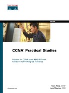
Before you start configuring the Frame Relay switch, take a look at how the lab routers are connected to the Cisco 2523 acting as the Frame Relay switch. Figure B-7 illustrates the physical connections.
As you can see from Figure B-7, R3 will be the “hub” site and requires two PVCs and DLCIs to be configured on interface S0 of the Cisco 2523. R2 and R4 need only one PVC and one DLCI. Begin by configuring the router as a Frame Relay switch.
Table B-1 defines the steps to configuring a Cisco router as a Frame Relay switch.
Table B-1. Configuring a Cisco Router as a Frame Relay Switch
| Step | Description | Command |
|---|---|---|
Step 1 | Enable Frame Relay switching. | frame-relay switching |
Step 2 | Configure Frame Relay encapsulation, Frame Relay LMI type, Frame Relay DCE interface mode, and clock rate on individual interfaces. | encapsulation frame-relay frame-relay lmi-type ansi frame-relay intf-type dce clock rate 64000[1] |
Step 3 | Configure DLCI to interface mappings on individual interfaces. | frame-relay route {local-dlci} interface {outgoing interface and number} {outgoing-dlci} |
[1] The clock rate is 64000 because the Cisco 2523 has both synchronous and asynchronous serial interfaces, and the asynchronous interfaces support only 64000 bps. | ||
The first thing is to connect to the Cisco 2523's console port. There is no configuration on the router at this point. You should be in setup mode or at the Router> prompt. If you are in setup mode, just exit this mode (Ctrl-c).
When you are into the router, give it a host name of Frame-Switch.
Router>en
Router#config t
Enter configuration commands, one per line.  End with CNTL/Z.
Router(config)#hostname Frame-Switch
Do not worry about passwords and Telnet connectivity. This router will be a standalone Frame Relay switch. If you need to access it, you will connect to the console port.
Begin with the first step documented in Table B-1, and enable Frame Relay switching on the router. Example B-1 illustrates this configuration step.
Example B-1. Enable Frame Relay Switching
Frame-Switch(config)#frame-relay switching
Frame-Switch(config)#
After the Frame Relay switching process has been started, configure the individual interfaces for the Frame Relay switch. This includes changing the encapsulation type to frame-relay and changing the LMI type to ANSI. Because all interfaces on the Frame Relay switch are DCEs (refer to the Figure B-7), they will need to be changed to the Frame
Relay type DCE and must have the clock rate command issued as well. Example B-2 demonstrates these commands for interface Serial0.
Example B-2. Frame-Relay Commands for Serial0
Frame-Switch(config)#int serial0
Frame-Switch(config-if)#encapsulation frame-relay
Frame-Switch(config-if)#frame-relay lmi-type ansi
Frame-Switch(config-if)#frame-relay intf-type dce
Frame-Switch(config-if)#clock rate 64000
Now that all the Frame Relay commands have been set, you need to map the local DLCI of this interface to the outgoing DLCI and port. Because the Serial0 interface has two PVCs, it needs two mappings. Example B-3 shows the commands.
Example B-3. DLCI-to-Interface Mappings for Serial0
Frame-Switch(config-if)#frame-relay route 100 interface serial 2 101
Frame-Switch(config-if)#frame-relay route 200 interface serial 1 201
Frame-Switch(config-if)#no shutdown
From Figure B-7, you know that Serial 0 has two PVCs, one to R2 and one to R4. The first highlighted portion of lines 1 and 2 in Example B-3 point out the local DLCI that will be advertised out Serial 0. Therefore, R3 will see DLCI 100 and DLCI 200 because R3 is connected to the Frame Relay switch on Serial0. The second portion of highlighting in lines 1 and 2 marks the outgoing interface to which each DLCI is mapped. Therefore, anything coming from R3 on DLCI 100 will be sent to Serial2, and anything coming from R3 on DLCI 200 will be sent to Serial1. The last portion of highlighting in lines 1 and 2 indicates the DLCI assigned to the outgoing port. So, anything coming from R3 on DLCI 100 will go out Serial2 to DLCI 101, and anything coming from R3 on DLCI 200 will go out Serial1 to DLCI 201. Don't forget to remove the interfaces from shutdown mode.
The next thing you need to do is perform a similar mapping statement on interfaces Serial1 and Serial2, except that the numbers will be reversed. See Example B-4.
Example B-4. Frame Relay Commands and DLCI-to-Interface Mappings for Serial1
Frame-Switch(config)#interface serial1
Frame-Switch(config-if)#encapsulation frame-relay
Frame-Switch(config-if)#frame-relay lmi-type ansi
Frame-Switch(config-if)#frame-relay intf-type dce
Frame-Switch(config-if)#clock rate 64000
Frame-Switch(config-if)#frame-relay route 201 interface serial 0 200
Frame-Switch(config-if)#no shutdown
The highlighted portion of the configuration shows the local DLCI (201), the outgoing interface (Serial0), and the outgoing DLCI (200). Next, do the same for interface Serial2. See Example B-5.
Example B-5. Frame-Relay Commands and DLCI-to-Interface Mappings on Serial2
Frame-Switch(config)#interface serial2
Frame-Switch(config-if)#encapsulation frame-relay
Frame-Switch(config-if)#frame-relay lmi-type ansi
Frame-Switch(config-if)#frame intf-type dce
Frame-Switch(config-if)#clock rate 64000
Frame-Switch(config-if)#frame-relay route 101 interface serial 0 100
Frame-Switch(config-if)#no shut
Frame-Switch(config-if)#
The highlighted portion of the configuration shows the local DLCI (101), the outgoing interface (Serial0), and the outgoing DLCI (100). At this point, you have a functional Frame Relay switch. You will be able to verify the connections in Chapter 7, “Router Interface Configuration,” but for now, take a look at the configuration and do a show frame-relay route to verify that the configuration matches the lab diagram. Example B-6 shows the running-config file. Notice where the commands are located in the configuration file.
Example B-6. Output from show running-config
Frame-Switch#show running-config
Building configuration...

Current configuration:
!
version 11.2
no service password-encryption
no service udp-small-servers
no service tcp-small-servers
!
hostname Frame-Switch
!
!
frame-relay switching
!
interface Serial0
 no ip address
 encapsulation frame-relay
 clockrate 64000
 frame-relay lmi-type ansi
 frame-relay intf-type dce
 frame-relay route 100 interface serial2 101
 frame-relay route 200 interface Serial1 201
!
interface Serial1
 no ip address
 encapsulation frame-relay
 clockrate 64000
 frame-relay lmi-type ansi
 frame-relay intf-type dce
 frame-relay route 201 interface Serial0 200
!
interface Serial2
 no ip address
 encapsulation frame-relay
 clockrate 64000
 frame-relay lmi-type ansi
 frame-relay intf-type dce
 frame-relay route 101 interface Serial0 100
!
interface Serial3
 no ip address
 shutdown
!
interface Serial4
 no ip address
 shutdown
!
interface Serial5
 no ip address
 shutdown
!
interface Serial6
 no ip address
 shutdown
!
interface Serial7
 no ip address
 shutdown
!
interface Serial8
 no ip address
 shutdown
!
interface Serial9
 no ip address
 shutdown
!
interface TokenRing0
 no ip address
 shutdown
!
interface BRI0
 no ip address
 shutdown
!
no ip classless
!
!
line con 0
 exec-timeout 0 0
line aux 0
line vty 0 4
 login
!
end

Frame-Switch#
The highlighted portions illustrate all the Frame Relay configuration tasks that you completed. Notice that none of the interfaces has IP addresses, nor do any of the interfaces need them. You are only mapping DLCIs to interfaces. This is a Layer 2 function, not a Layer 3 function, therefore, no IP address are needed.
The show frame-relay route command is a useful command in determining that your configuration is correct. Example B-7 shows the output from this command.
Example B-7. Output from show frame-relay route Command
Frame-Switch#show frame-relay route
Input Intf      Input Dlci      Output Intf     Output Dlci     Status
Serial0         100             Serial2         101             inactive
Serial0         200             Serial1         201             inactive
Serial1         201             Serial0         200             inactive
Serial2         101             Serial0         100             inactive
Frame-Switch#
From this output, you can see that the Input Dlci matches the correct interfaces from the lab diagram in Figure B-7. You also can see that Output Intf and Output Dlci match to the correct interfaces and DLCIs as well. From here, you can assume that everything is configured correctly. The status will be inactive until you configure the Frame Relay interfaces on R2, R3, and R4 and remove them from shutdown mode.