
Now let’s discuss another (indirectly related) predicament in securing DNS traffic—that is, the manipulation of the HOSTS file, a technique frequently used by malware. The HOSTS file is used by the operating system to map hostnames to IP addresses as described before. The HOSTS file is a plaintext file located in the %systemroot% system32i386driversetc/ folder in Windows and at /etc/hosts in UNIX/Linux systems. The file simply consists of a list of IP addresses with their corresponding hostnames.
Depending on its configuration, the computer refers to the HOSTS file before issuing a DNS request to a DNS server. Most operating systems give preference to HOSTS file–returned IP addresses’ details rather than the ones from the DNS server because the HOSTS file is generally under the direct control of the local system administrator.
As covered previously, in the early days of the Internet and prior to the adoption of DNS, HOSTS files were the primary source of determining a host’s network addresses from its hostname. With the increase in the number of hosts connected to the Internet, maintaining HOSTS files became next to impossible and ultimately led to the creation of DNS.
Due to the important role of HOSTS files, they are frequently targeted by malware to propagate across systems connected on a local network. Once a malicious program takes over the HOSTS file, it can divert traffic from its intended destination to websites hosting malicious content, for example. A common example of HOSTS file manipulation carried out by malware involves blocking users from visiting antivirus update websites. This is usually done by mapping target hostnames to the loopback interface IP address 127.0.0.1. The most effective technique for preventing HOSTS file intrusions is to set it as a read-only file and implement a host-based IDS that watches for critical file modification attempts.
Attackers don’t always have to go through all this trouble to divert traffic to rogue destinations. They can also use some very simple techniques that are surprisingly effective in routing naive users to unintended destinations. The most common approach is known as URL hiding. Hypertext Markup Language (HTML) documents and e-mail messages allow users to attach or embed hyperlinks in any given text, such as the “Click Here” links you commonly see in e-mail messages or web pages. Attackers misuse hyperlinks to deceive unsuspecting users into clicking rogue links.
Let’s say a malicious attacker creates an unsuspicious text, www.good.site, but embeds the link to an abusive website, www.bad.site. People are likely to click the www.good.site link without knowing that they are actually being taken to the bad site. In addition, attackers also use character encoding to obscure web addresses that may arouse user suspicion.
Domain Name Registration Issues
We’ll now have a look at some legal aspects of domain registration. Although these do not pose a direct security risk to your DNS servers or your IT infrastructure, ignorance of them may risk your very domain name on the Internet, thus jeopardizing your entire online presence. Awareness of domain grabbing and cyber squatting issues will help you better plan out your online presence and allow you to steer clear of these traps.
ICANN promotes a governance model that follows a first-come, first-serve policy when registering domain names, regardless of trademark considerations. This has led to a race among individuals to secure attractive and prominent domains. Among these are cyber squatters, individuals who register prominent or established names, hoping to sell these later to real-world businesses that may require these names to establish their online presence. So if you were preparing to launch a huge business called SecurityRUS, a cyber squatter could go purchase this domain name, and its various formats, at a low price. This person knows you will need this domain name for your website, so they will mark up the price by 1,000 percent and force you to pay this higher rate.
Another tactic employed by cyber squatters is to watch for top-used domain names that are approaching their re-registration date. If you forget to re-register the domain name you have used for the last ten years, a cyber squatter can purchase the name and then require you to pay a huge amount of money just to use the name you have owned and used for years. These are opportunist types of attacks.
To protect your organization from these threats, it is essential that you register a domain as soon as your company conceives of launching a new brand or applies for a new trademark. Registering important domains for longer periods, such as for five or ten years, instead of annually renewing them, reduces the chances of domains slipping out to cyber squatters. Another technique is to register nearby domains as well. For example, if you own the domain something.com, registering some-thing.com and something.net may be a good idea because this will prevent someone else from occupying these domains for furtive purposes.
E-mail Services
A user has an e-mail client that is used to create, modify, address, send, receive, and forward messages. This e-mail client may provide other functionality, such as a personal address book and the ability to add attachments, set flags, recall messages, and store messages within different folders.
A user’s e-mail message is of no use unless it can actually be sent somewhere. This is where Simple Mail Transfer Protocol (SMTP) comes in. In e-mail clients, SMTP works as a message transfer agent, as shown in Figure 4-35, and moves the message from the user’s computer to the mail server when the user clicks the Send button. SMTP also functions as a message transfer protocol between e-mail servers. Lastly, SMTP is a message-exchange addressing standard, and most people are used to seeing its familiar addressing scheme: [email protected].
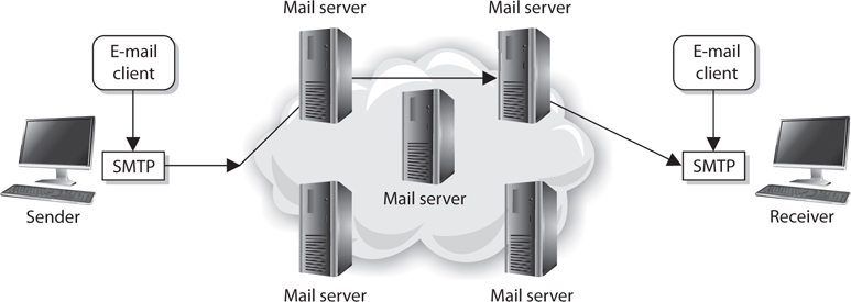
Figure 4-35 SMTP works as a transfer agent for e-mail messages.
Many times, a message needs to travel throughout the Internet and through different mail servers before it arrives at its destination mail server. SMTP is the protocol that carries this message, and it works on top of TCP because it is a reliable protocol and provides sequencing and acknowledgments to ensure the e-mail message arrived successfully at its destination.
The user’s e-mail client must be SMTP-compliant to be properly configured to use this protocol. The e-mail client provides an interface to the user so the user can create and modify messages as needed, and then the client passes the message off to the SMTP application layer protocol. So, to use the analogy of sending a letter via the post office, the e-mail client is the typewriter that a person uses to write the message, SMTP is the mail courier who picks up the mail and delivers it to the post office, and the post office is the mail server. The mail server has the responsibility of understanding where the message is heading and properly routing the message to that destination.
The mail server is often referred to as an SMTP server. The most common SMTP server software within the UNIX world is Sendmail, which is actually an e-mail server application. This means that UNIX uses Sendmail software to store, maintain, and route e-mail messages. Within the Microsoft world, Microsoft Exchange is mostly used, and in Novell, GroupWise is the common SMTP server. SMTP works closely with two mail server protocols, POP and IMAP, which are explained in the following sections.
POP
Post Office Protocol (POP) is an Internet mail server protocol that supports incoming and outgoing messages. A mail server that uses POP, apart from storing and forwarding e-mail messages, works with SMTP to move messages between mail servers.
A smaller company may have one POP server that holds all employee mailboxes, whereas larger companies may have several POP servers, one for each department within the organization. There are also Internet POP servers that enable people all over the world to exchange messages. This system is useful because the messages are held on the mail server until users are ready to download their messages, instead of trying to push messages right to a person’s computer, which may be down or offline.
The e-mail server can implement different authentication schemes to ensure an individual is authorized to access a particular mailbox, but this is usually handled through usernames and passwords.
IMAP
Internet Message Access Protocol (IMAP) is also an Internet protocol that enables users to access mail on a mail server. IMAP provides all the functionalities of POP, but has more capabilities. If a user is using POP, when he accesses his mail server to see if he has received any new messages, all messages are automatically downloaded to his computer. Once the messages are downloaded from the POP server, they are usually deleted from that server, depending upon the configuration. POP can cause frustration for mobile users because the messages are automatically pushed down to their computer or device and they may not have the necessary space to hold all the messages. This is especially true for mobile devices that can be used to access e-mail servers. This is also inconvenient for people checking their mail on other people’s computers. If Christina checks her e-mail on Jessica’s computer, all of Christina’s new mail could be downloaded to Jessica’s computer.

NOTE POP is commonly used for Internet-based e-mail accounts (Gmail, Yahoo!, etc.), while IMAP is commonly used for corporate e-mail accounts.
If a user uses IMAP instead of POP, she can download all the messages or leave them on the mail server within her remote message folder, referred to as a mailbox. The user can also manipulate the messages within this mailbox on the mail server as if the messages resided on her local computer. She can create or delete messages, search for specific messages, and set and clear flags. This gives the user much more freedom and keeps the messages in a central repository until the user specifically chooses to download all messages from the mail server.
IMAP is a store-and-forward mail server protocol that is considered POP’s successor. IMAP also gives administrators more capabilities when it comes to administering and maintaining the users’ messages.
E-mail Relaying
Most companies have their public mail servers in their DMZ and may have one or more mail servers within their internal LAN. The mail servers in the DMZ are in this protected space because they are directly connected to the Internet. These servers should be tightly locked down and their relaying mechanisms should be correctly configured. Mail servers use a relay agent to send a message from one mail server to another. This relay agent needs to be properly configured so a company’s mail server is not used by a malicious entity for spamming activity.
Spamming usually is illegal, so the people doing the spamming do not want the traffic to seem as though it originated from their equipment. They will find mail servers on the Internet, or within company DMZs, that have loosely configured relaying mechanisms and use these servers to send their spam. If relays are configured “wide open” on a mail server, the mail server can be used to receive any mail message and send it on to any intended recipients, as shown in Figure 4-36. This means that if a company does not properly configure its mail relaying, its server can be used to distribute advertisements for other companies, spam messages, and pornographic material. It is important that mail servers have proper antispam features enabled, which are actually antirelaying features. A company’s mail server should only accept mail destined for its domain and should not forward messages to other mail servers and domains that may be suspicious.
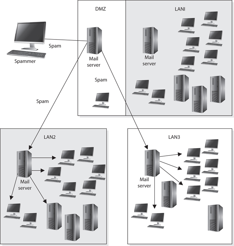
Figure 4-36 Mail servers can be used for relaying spam if relay functionality is not properly configured.
Many companies also employ antivirus and content-filtering applications on their mail servers to try and stop the spread of malicious code and not allow unacceptable messages through the e-mail gateway. It is important to filter both incoming and outgoing messages. This helps ensure that inside employees are not spreading viruses or sending out messages that are against company policy.
E-mail Threats
E-mail spoofing is a technique used by malicious users to forge an e-mail to make it appear to be from a legitimate source. Usually, such e-mails appear to be from known and trusted e-mail addresses when they are actually generated from a malicious source. This technique is widely used by attackers these days for spamming and phishing purposes. An attacker tries to acquire the target’s sensitive information, such as username and password or bank account credentials. Sometimes, the e-mail messages contain a link of a known website when it is actually a fake website used to trick the user into revealing his information.
E-mail spoofing is done by modifying the fields of e-mail headers, such as the From, Return-Path, and Reply-To fields, so the e-mail appears to be from a trusted source. This results in an e-mail looking as though it is from a known e-mail address. Mostly the From field is spoofed, but some scams have modified the Reply-To field to the attacker’s e-mail address. E-mail spoofing is caused by the lack of security features in SMTP. When SMTP technologies were developed, the concept of e-mail spoofing didn’t exist, so countermeasures for this type of threat were not embedded into the protocol. A user could use an SMTP server to send e-mail to anyone from any e-mail address.
SMTP authentication (SMTP-AUTH) was developed to provide an access control mechanism. This extension comprises an authentication feature that allows clients to authenticate to the mail server before an e-mail is sent. Servers using the SMTP-AUTH extension are configured in such a manner that their clients are obliged to use the extension so that the sender can be authenticated.
E-mail spoofing can be mitigated in several ways. The SMTP server can be configured to prevent unauthenticated users from sending e-mails. It is important to always log all the connections to your mail servers so that unsolicited e-mails can be traced and tracked. It’s also advised that you filter incoming and outgoing traffic toward mail servers through a firewall to prevent generic network-level attacks, such as packet spoofing, distributed denial-of-service (DDoS) attacks, and so on. Important e-mails can be communicated over encrypted channels so that the sender and receiver are properly authenticated.
Another way to deal with the problem of forged e-mail messages is by using Sender Policy Framework (SPF), which is an e-mail validation system designed to prevent e-mail spam by detecting e-mail spoofing by verifying the sender’s IP address. SPF allows administrators to specify which hosts are allowed to send e-mail from a given domain by creating a specific SPF record in DNS. Mail exchanges use DNS to check that mail from a given domain is being sent by a host sanctioned by that domain’s administrators.
Phishing is a social engineering attack that is commonly carried out through maliciously crafted e-mail messages. The goal is to get someone to click a malicious link or for the victim to send the attacker some confidential data (Social Security number, account number, etc.). The attacker crafts an e-mail that seems to originate from a trusted source and sends it out to many victims at one time. A spear phishing attack zeroes in on specific people. So if an attacker wants your specific information because she wants to break into your bank account, she could gather information about you via Facebook, LinkedIn, or other resources and create an e-mail purporting to be from someone she thinks you will trust. A similar attack is called whaling. In a whaling attack an attacker usually identifies some “big fish” in an organization (CEO, CFO, COO, CSO) and targets them because they have access to some of the most sensitive data in the organization. The attack is finely tuned to achieve the highest likelihood of success.
E-mail is, of course, a critical communication tool, but is the most commonly misused channel for malicious activities.
Network Address Translation
When computers need to communicate with each other, they must use the same type of addressing scheme so everyone understands how to find and talk to one another. The Internet uses the IP address scheme as discussed earlier in the chapter, and any computer or network that wants to communicate with other users on the network must conform to this scheme; otherwise, that computer will sit in a virtual room with only itself to talk to.
However, IP addresses have become scarce (until the full adoption of IPv6) and expensive. So some smart people came up with network address translation (NAT), which enables a network that does not follow the Internet’s addressing scheme to communicate over the Internet.
Private IP addresses have been reserved for internal LAN address use, as outlined in RFC 1918. These addresses can be used within the boundaries of a company, but they cannot be used on the Internet because they will not be properly routed. NAT enables a company to use these private addresses and still be able to communicate transparently with computers on the Internet.
The following lists current private IP address ranges:
• 10.0.0.0–10.255.255.255 Class A networks
• 172.16.0.0–172.31.255.255 Class B networks
• 192.168.0.0–192.168.255.255 Class C networks
NAT is a gateway that lies between a network and the Internet (or another network) that performs transparent routing and address translation. Because IP addresses were depleting fast, IPv6 was developed in 1999, and was intended to be the long-term fix to the address shortage problem. NAT was developed as the short-term fix to enable more companies to participate on the Internet. However, to date, IPv6 is slow in acceptance and implementation, while NAT has caught on like wildfire. Many firewall vendors have implemented NAT into their products, and it has been found that NAT actually provides a great security benefit. When attackers want to hack a network, they first do what they can to learn all about the network and its topology, services, and addresses. Attackers cannot easily find out a company’s address scheme and its topology when NAT is in place, because NAT acts like a large nightclub bouncer by standing in front of the network and hiding the true IP scheme.
NAT hides internal addresses by centralizing them on one device, and any frames that leave that network have only the source address of that device, not of the actual internal computer that sends the message. So when a message comes from an internal computer with the address of 10.10.10.2, for example, the message is stopped at the device running NAT software, which happens to have the IP address of 1.2.3.4. NAT changes the header of the packet from the internal address, 10.10.10.2, to the IP address of the NAT device, 1.2.3.4. When a computer on the Internet replies to this message, it replies to the address 1.2.3.4. The NAT device changes the header on this reply message to 10.10.10.2 and puts it on the wire for the internal user to receive.
Three basic types of NAT implementations can be used:
• Static mapping The NAT software has a pool of public IP addresses configured. Each private address is statically mapped to a specific public address. So computer A always receives the public address x, computer B always receives the public address y, and so on. This is generally used for servers that need to keep the same public address at all times.
• Dynamic mapping The NAT software has a pool of IP addresses, but instead of statically mapping a public address to a specific private address, it works on a first-come, first-served basis. So if Bob needs to communicate over the Internet, his system makes a request to the NAT server. The NAT server takes the first IP address on the list and maps it to Bob’s private address. The balancing act is to estimate how many computers will most likely need to communicate outside the internal network at one time. This estimate is the number of public addresses the company purchases, instead of purchasing one public address for each computer.
• Port address translation (PAT) The company owns and uses only one public IP address for all systems that need to communicate outside the internal network. How in the world could all computers use the exact same IP address? Good question. Here’s an example: The NAT device has an IP address of 127.50.41.3. When computer A needs to communicate with a system on the Internet, the NAT device documents this computer’s private address and source port number (10.10.44.3; port 43,887). The NAT device changes the IP address in the computer’s packet header to 127.50.41.3, with the source port 40,000. When computer B also needs to communicate with a system on the Internet, the NAT device documents the private address and source port number (10.10.44.15; port 23,398) and changes the header information to 127.50.41.3 with source port 40,001. So when a system responds to computer A, the packet first goes to the NAT device, which looks up the port number 40,000 and sees that it maps to computer A’s real information. So the NAT device changes the header information to address 10.10.44.3 and port 43,887 and sends it to computer A for processing. A company can save a lot more money by using PAT because the company needs to buy only a few public IP addresses, which are used by all systems in the network.
Most NAT implementations are stateful, meaning they keep track of a communication between the internal host and an external host until that session is ended. The NAT device needs to remember the internal IP address and port to send the reply messages back. This stateful characteristic is similar to stateful-inspection firewalls, but NAT does not perform scans on the incoming packets to look for malicious characteristics. Instead, NAT is a service usually performed on routers or gateway devices within a company’s screened subnet.
Although NAT was developed to provide a quick fix for the depleting IP address problem, it has actually put the problem off for quite some time. The more companies that implement private address schemes, the less likely IP addresses will become scarce. This has been helpful to NAT and the vendors that implement this technology, but it has put the acceptance and implementation of IPv6 much farther down the road.
Routing Protocols
Individual networks on the Internet are referred to as autonomous systems (ASs). These ASs are independently controlled by different service providers and organizations. An AS is made up of routers, which are administered by a single entity and use a common Interior Gateway Protocol (IGP) within the boundaries of the AS. The boundaries of these ASs are delineated by border routers. These routers connect to the border routers of other ASs and run interior and exterior routing protocols. Internal routers connect to other routers within the same AS and run interior routing protocols. So, in reality, the Internet is just a network made up of ASs and routing protocols.
NOTE As an analogy, just as the world is made up of different countries, the Internet is made up of different ASs. Each AS has delineation boundaries just as countries do. Countries can have their own languages (Spanish, Arabic, Russian). Similarly, ASs have their own internal routing protocols. Countries that speak different languages need to have a way of communicating to each other, which could happen through interpreters. ASs need to have a standardized method of communicating and working together, which is where external routing protocols come into play.
The architecture of the Internet that supports these various ASs is created so that no entity that needs to connect to a specific AS has to know or understand the interior routing protocols that are being used. Instead, for ASs to communicate, they just have to be using the same exterior routing protocols (see Figure 4-37). As an analogy, suppose you want to deliver a package to a friend who lives in another state. You give the package to your brother, who is going to take a train to the edge of the state and hand it to the postal system at that junction. Thus, you know how your brother will arrive at the edge of the state—by train. You do not know how the postal system will then deliver your package to your friend’s house (truck, car, bus), but that is not your concern. It will get to its destination without your participation. Similarly, when one network communicates with another network, the first network puts the data packet (package) on an exterior protocol (train), and when the data packet gets to the border router (edge of the state), the data is transferred to whatever interior protocol is being used on the receiving network.
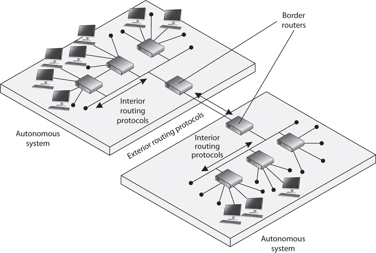
Figure 4-37 Autonomous systems
NOTE Routing protocols are used by routers to identify a path between the source and destination systems.
Dynamic vs. Static
Routing protocols can be dynamic or static. A dynamic routing protocol can discover routes and build a routing table. Routers use these tables to make decisions on the best route for the packets they receive. A dynamic routing protocol can change the entries in the routing table based on changes that take place to the different routes. When a router that is using a dynamic routing protocol finds out that a route has gone down or is congested, it sends an update message to the other routers around it. The other routers use this information to update their routing table, with the goal of providing efficient routing functionality. A static routing protocol requires the administrator to manually configure the router’s routing table. If a link goes down or there is network congestion, the routers cannot tune themselves to use better routes.
NOTE Route flapping refers to the constant changes in the availability of routes. Also, if a router does not receive an update that a link has gone down, the router will continue to forward packets to that route, which is referred to as a black hole.
Distance-Vector vs. Link-State
Two main types of routing protocols are used: distance-vector and link-state routing. Distance-vector routing protocols make their routing decisions based on the distance (or number of hops) and a vector (a direction). The protocol takes these variables and uses them with an algorithm to determine the best route for a packet. Link-state routing protocols build a more accurate routing table because they build a topology database of the network. These protocols look at more variables than just the number of hops between two destinations. They use packet size, link speed, delay, network load, and reliability as the variables in their algorithms to determine the best routes for packets to take.
So, a distance-vector routing protocol only looks at the number of hops between two destinations and considers each hop to be equal. A link-state routing protocol sees more pieces to the puzzle than just the number of hops, but understands the status of each of those hops and makes decisions based on these factors also. As you will see, RIP is an example of a distance-vector routing protocol, and OSPF is an example of a link-state routing protocol. OSPF is preferred and is used in large networks. RIP is still around but should only be used in smaller networks.
Interior Routing Protocols
Interior Routing Protocols (also known as Interior Gateway Protocols) route traffic within the same AS. Just like the process for flying from one airport to another is different if you travel domestically or internationally, routing protocols are designed differently depending on which side of the AS boundary they operate. De facto and proprietary interior protocols are being used today. The following are just a few of them:
• Routing Information Protocol RIP is a standard that outlines how routers exchange routing table data and is considered a distance-vector protocol, which means it calculates the shortest distance between the source and destination. It is considered a legacy protocol because of its slow performance and lack of functionality. It should only be used in small networks. RIP version 1 has no authentication, and RIP version 2 sends passwords in cleartext or hashed with MD5. RIPng is the third generation of this venerable protocol. It is very similar to the version 2, but is designed for IPv6 routing.
• Open Shortest Path First OSPF uses link-state algorithms to send out routing table information. The use of these algorithms allows for smaller, more frequent routing table updates to take place. This provides a more stable network than RIP, but requires more memory and CPU resources to support this extra processing. OSPF allows for a hierarchical routing network that has a backbone link connecting all subnets together. OSPF has replaced RIP in many networks today. Authentication can take place with cleartext passwords or hashed passwords, or you can choose to configure no authentication on the routers using this protocol. The latest OSPF is version 3. Though it was designed to support IPv6, it also supports IPv4. Among the most important improvements is that OSPFv3 uses IPSec for authentication.
• Interior Gateway Routing Protocol IGRP is a distance-vector routing protocol that was developed by, and is proprietary to, Cisco Systems. Whereas RIP uses one criterion to find the best path between the source and destination, IGRP uses five criteria to make a “best route” decision. A network administrator can set weights on these different metrics so that the protocol works best in that specific environment.
• Enhanced Interior Gateway Routing Protocol EIGRP is a Cisco-proprietary and advanced distance-vector routing protocol. It allows for faster router table updates than its predecessor IGRP and minimizes routing instability, which can occur after topology changes. Routers exchange messages that contain information about bandwidth, delay, load, reliability, and MTU of the path to each destination as known by the advertising router. The latest version is 4, which is able to support multiple network protocols such as IPv4, IPv6, IPX, and AppleTalk.
• Virtual Router Redundancy Protocol VRRP is used in networks that require high availability where routers as points of failure cannot be tolerated. It is designed to increase the availability of the default gateway by advertising a “virtual router” as a default gateway. Two physical routers (primary and secondary) are mapped to one virtual router. If one of the physical routers fails, the other router takes over the workload.
• Intermediate System to Intermediate System IS-IS is a link-state protocol that allows each router to independently build a database of a network’s topology. Similar to the OSPF protocol, it computes the best path for traffic to travel. It is a classless and hierarchical routing protocol that is vendor neutral. Unlike other protocols (e.g., RIP and OSPF), IS-IS does not use IP addresses. Instead, it uses ISO addresses, which means that the protocol didn’t have to be redesigned to support IPv6.

TIP Although most routing protocols have authentication functionality, many routers do not have this functionality enabled.
Exterior Routing Protocols
The exterior routing protocols used by routers connecting different ASs are generically referred to as exterior gateway protocols (EGPs). The Border Gateway Protocol (BGP) enables routers on different ASs to share routing information to ensure effective and efficient routing between the different AS networks. BGP is commonly used by Internet service providers to route data from one location to the next on the Internet.
NOTE There is an exterior routing protocol called Exterior Gateway Protocol, but it has been widely replaced by BGP, and now the term “exterior gateway protocol” and the acronym EGP are used to refer generically to a type of protocol rather than to specify the outdated protocol.
BGP uses a combination of link-state and distance-vector routing algorithms. It creates a network topology by using its link-state functionality and transmits updates on a periodic basis instead of continuously, which is how distance-vector protocols work. Network administrators can apply weights to the different variables used by link-state routing protocols when determining the best routes. These configurations are collectively called the routing policy.
Routing Protocol Attacks
Several types of attacks can take place on routers through their routing protocols. A majority of the attacks have the goal of misdirecting traffic through the use of spoofed ICMP messages. An attacker can masquerade as another router and submit routing table information to the victim router. After the victim router integrates this new information, it may be sending traffic to the wrong subnets or computers, or even to a nonexistent address (black hole). These attacks are successful mainly when routing protocol authentication is not enabled. When authentication is not required, a router can accept routing updates without knowing whether or not the sender is a legitimate router. An attacker could divert a company’s traffic to reveal confidential information or to just disrupt traffic, which would be considered a DoS attack.
Other types of DoS attacks exist, such as flooding a router port, buffer overflows, and SYN floods. Since there are many different types of attacks that can take place, there are just as many countermeasures to be aware of to thwart these types of attacks. Most of these countermeasures involve authentication and encryption of routing data as it is transmitted back and forth through the use of shared keys or IPSec.
Networking Devices
Several types of devices are used in LANs, MANs, and WANs to provide intercommunication among computers and networks. We need to have physical devices throughout the network to actually use all the protocols and services we have covered up to this point. The different networking devices vary according to their functionality, capabilities, intelligence, and network placement. We will look at the following devices:
• Repeaters
• Bridges
• Routers
• Switches
Repeaters
A repeater provides the simplest type of connectivity because it only repeats electrical signals between cable segments, which enables it to extend a network. Repeaters work at the physical layer and are add-on devices for extending a network connection over a greater distance. The device amplifies signals because signals attenuate the farther they have to travel.
Repeaters can also work as line conditioners by actually cleaning up the signals. This works much better when amplifying digital signals than when amplifying analog signals because digital signals are discrete units, which makes extraction of background noise from them much easier for the amplifier. If the device is amplifying analog signals, any accompanying noise often is amplified as well, which may further distort the signal.
A hub is a multiport repeater. A hub is often referred to as a concentrator because it is the physical communication device that allows several computers and devices to communicate with each other. A hub does not understand or work with IP or MAC addresses. When one system sends a signal to go to another system connected to it, the signal is broadcast to all the ports, and thus to all the systems connected to the concentrator.
Bridges
A bridge is a LAN device used to connect LAN segments. It works at the data link layer and therefore works with MAC addresses. A repeater does not work with addresses; it just forwards all signals it receives. When a frame arrives at a bridge, the bridge determines whether or not the MAC address is on the local network segment. If the MAC address is not on the local network segment, the bridge forwards the frame to the necessary network segment.
A bridge is used to divide overburdened networks into smaller segments to ensure better use of bandwidth and traffic control. A bridge amplifies the electrical signal, as does a repeater, but it has more intelligence than a repeater and is used to extend a LAN and enable the administrator to filter frames so he can control which frames go where.
When using bridges, you have to watch carefully for broadcast storms. Because bridges can forward all traffic, they forward all broadcast packets as well. This can overwhelm the network and result in a broadcast storm, which degrades the network bandwidth and performance.
Three main types of bridges are used: local, remote, and translation. A local bridge connects two or more LAN segments within a local area, which is usually a building. A remote bridge can connect two or more LAN segments over a MAN by using telecommunications links. A remote bridge is equipped with telecommunications ports, which enable it to connect two or more LANs separated by a long distance and can be brought together via telephone or other types of transmission lines. A translation bridge is needed if the two LANs being connected are different types and use different standards and protocols. For example, consider a connection between a Token Ring network and an Ethernet network. The frames on each network type are different sizes, the fields contain different protocol information, and the two networks transmit at different speeds. If a regular bridge were put into place, Ethernet frames would go to the Token Ring network, and vice versa, and neither would be able to understand messages that came from the other network segment. A translation bridge does what its name implies—it translates between the two network types.
The following list outlines the functions of a bridge:
• Segments a large network into smaller, more controllable pieces.
• Uses filtering based on MAC addresses.
• Joins different types of network links while retaining the same broadcast domain.
• Isolates collision domains within the same broadcast domain.
• Bridging functionality can take place locally within a LAN or remotely to connect two distant LANs.
• Can translate between protocol types.

EXAM TIP Do not confuse routers with bridges. Routers work at the network layer and filter packets based on IP addresses, whereas bridges work at the data link layer and filter frames based on MAC addresses. Routers usually do not pass broadcast information, but bridges do pass broadcast information.
Forwarding Tables
A bridge must know how to get a frame to its destination—that is, it must know to which port the frame must be sent and where the destination host is located. Years ago, network administrators had to type route paths into bridges so the bridges had static paths indicating where to pass frames that were headed for different destinations. This was a tedious task and prone to errors. Today, bridges use transparent bridging.
If transparent bridging is used, a bridge starts to learn about the network’s environment as soon as it is powered on and as the network changes. It does this by examining frames and making entries in its forwarding tables. When a bridge receives a frame from a new source computer, the bridge associates this new source address and the port on which it arrived. It does this for all computers that send frames on the network. Eventually, the bridge knows the address of each computer on the various network segments and to which port each is connected. If the bridge receives a request to send a frame to a destination that is not in its forwarding table, it sends out a query frame on each network segment except for the source segment. The destination host is the only one that replies to this query. The bridge updates its table with this computer address and the port to which it is connected and forwards the frame.
Many bridges use the Spanning Tree Algorithm (STA), which adds more intelligence to the bridges. STA ensures that frames do not circle networks forever, provides redundant paths in case a bridge goes down, assigns unique identifiers to each bridge, assigns priority values to these bridges, and calculates path costs. This creates much more efficient frame-forwarding processes by each bridge. STA also enables an administrator to indicate whether he wants traffic to travel certain paths instead of others.
If source routing is allowed, the packets contain the necessary information within them to tell the bridge or router where they should go. The packets hold the forwarding information so they can find their way to their destination without needing bridges and routers to dictate their paths. If the computer wants to dictate its forwarding information instead of depending on a bridge, how does it know the correct route to the destination computer? The source computer sends out explorer packets that arrive at the destination computer. These packets contain the route information the packets had to take to get to the destination, including what bridges and/or routers they had to pass through. The destination computer then sends these packets back to the source computer, and the source computer strips out the routing information, inserts it into the packets, and sends them on to the destination.

CAUTION External devices and border routers should not accept packets with source routing information within their headers, because that information will override what is laid out in the forwarding and routing tables configured on the intermediate devices. You want to control how traffic traverses your network; you don’t want packets to have this type of control and be able to go wherever they want. Source routing can be used by attackers to get around certain bridge and router filtering rules.
Routers
We are going up the chain of the OSI layers while discussing various networking devices. Repeaters work at the physical layer, bridges work at the data link layer, and routers work at the network layer. As we go up each layer, each corresponding device has more intelligence and functionality because it can look deeper into the frame. A repeater looks at the electrical signal. The bridge can look at the MAC address within the header. The router can peel back the first header information and look farther into the frame and find out the IP address and other routing information. The farther a device can look into a frame, the more decisions it can make based on the information within the frame.
Routers are layer 3, or network layer, devices that are used to connect similar or different networks. (For example, they can connect two Ethernet LANs or an Ethernet LAN to a Token Ring LAN.) A router is a device that has two or more interfaces and a routing table so it knows how to get packets to their destinations. It can filter traffic based on access control lists (ACLs), and it fragments packets when necessary. Because routers have more network-level knowledge, they can perform higher-level functions, such as calculating the shortest and most economical path between the sending and receiving hosts.
A router discovers information about routes and changes that take place in a network through its routing protocols (RIP, BGP, OSPF, and others). These protocols tell routers if a link has gone down, if a route is congested, and if another route is more economical. They also update routing tables and indicate if a router is having problems or has gone down.
The router may be a dedicated appliance or a computer running a networking operating system that is dual-homed. When packets arrive at one of the interfaces, the router compares those packets to its ACLs. This list indicates what packets are allowed in and what packets are denied. Access decisions are based on source and destination IP addresses, protocol type, and source and destination ports. An administrator may block all packets coming from the 10.10.12.0 network, any FTP requests, or any packets headed toward a specific port on a specific host, for example. This type of control is provided by the ACLs, which the administrator must program and update as necessary.
What actually happens inside the router when it receives a packet? Let’s follow the steps:
1. A packet is received on one of the interfaces of a router. The router views the routing data.
2. The router retrieves the destination IP network address from the packet.
3. The router looks at its routing table to see which port matches the requested destination IP network address.
4. If the router does not have information in its table about the destination address, it sends out an ICMP error message to the sending computer indicating that the message could not reach its destination.
5. If the router does have a route in its routing table for this destination, it decrements the TTL value and sees whether the MTU is different for the destination network. If the destination network requires a smaller MTU, the router fragments the datagram.
6. The router changes header information in the packet so the packet can go to the next correct router, or if the destination computer is on a connecting network, the changes made enable the packet to go directly to the destination computer.
7. The router sends the packet to its output queue for the necessary interface.
Table 4-8 provides a quick review of the differences between routers and bridges.
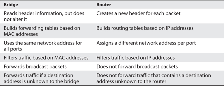
Table 4-8 Main Differences Between Bridges and Routers
When is it best to use a repeater, bridge, or router? A repeater is used if an administrator needs to expand a network and amplify signals so they do not weaken on longer cables. However, a repeater will also extend collision and broadcast domains.
Bridges work at the data link layer and have a bit more intelligence than a repeater. Bridges can do simple filtering and separate collision domains, but not broadcast domains. A bridge should be used when an administrator wants to divide a network into segments to reduce traffic congestion and excessive collisions.
A router splits up a network into collision domains and broadcast domains. A router gives more of a clear-cut division between network segments than repeaters or bridges. A router should be used if an administrator wants to have more defined control of where the traffic goes because more sophisticated filtering is available with routers, and when a router is used to segment a network, the result is more controllable sections.
A router is used when an administrator wants to divide a network along the lines of departments, workgroups, or other business-oriented divisions. A bridge divides segments based more on the traffic type and load.
Switches
Switches combine the functionality of a repeater and the functionality of a bridge. A switch amplifies the electrical signal, like a repeater, and has the built-in circuitry and intelligence of a bridge. It is a multiport connection device that provides connections for individual computers or other hubs and switches. Any device connected to one port can communicate with a device connected to another port with its own virtual private link. How does this differ from the way in which devices communicate using a bridge or a hub? When a frame comes to a hub, the hub sends the frame out through all of its ports. When a frame comes to a bridge, the bridge sends the frame to the port to which the destination network segment is connected. When a frame comes to a switch, the switch sends the frame directly to the destination computer or network, which results in a reduction of traffic. Figure 4-38 illustrates a network configuration that has computers directly connected to their corresponding switches.
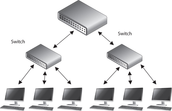
Figure 4-38 Switches enable devices to communicate with each other via their own virtual link.
On Ethernet networks, computers have to compete for the same shared network medium. Each computer must listen for activity on the network and transmit its data when it thinks the coast is clear. This contention and the resulting collisions cause traffic delays and use up precious bandwidth. When switches are used, contention and collisions are not issues, which results in more efficient use of the network’s bandwidth and decreased latency. Switches reduce or remove the sharing of the network medium and the problems that come with it.
A switch is a multiport bridging device, and each port provides dedicated bandwidth to the device attached to it. A port is bridged to another port so the two devices have an end-to-end private link. The switch employs full-duplex communication, so one wire pair is used for sending and another pair is used for receiving. This ensures the two connected devices do not compete for the same bandwidth.
Basic switches work at the data link layer and forward traffic based on MAC addresses. However, today’s layer 3, layer 4, and other layer switches have more enhanced functionality than layer 2 switches. These higher-level switches offer routing functionality, packet inspection, traffic prioritization, and QoS functionality. These switches are referred to as multilayered switches because they combine data link layer, network layer, and other layer functionalities.
Multilayered switches use hardware-based processing power, which enables them to look deeper within the packet, to make more decisions based on the information found within the packet, and then to provide routing and traffic management tasks. Usually this amount of work creates a lot of overhead and traffic delay, but multilayered switches perform these activities within an application-specific integrated circuit (ASIC). This means that most of the functions of the switch are performed at the hardware and chip level rather than at the software level, making it much faster than routers.
CAUTION While it is harder for attackers to sniff traffic on switched networks, they should not be considered safe just because switches are involved. Attackers commonly poison cache memory used on switches to divert traffic to their desired location.
Layer 3 and 4 Switches
Layer 2 switches only have the intelligence to forward a frame based on its MAC address and do not have a higher understanding of the network as a whole. A layer 3 switch has the intelligence of a router. It not only can route packets based on their IP addresses, but also can choose routes based on availability and performance. A layer 3 switch is basically a router on steroids, because it moves the route lookup functionality to the more efficient switching hardware level.
The basic distinction between layer 2, 3, and 4 switches is the header information the device looks at to make forwarding or routing decisions (data link, network, or transport OSI layers). But layer 3 and 4 switches can use tags, which are assigned to each destination network or subnet. When a packet reaches the switch, the switch compares the destination address with its tag information base, which is a list of all the subnets and their corresponding tag numbers. The switch appends the tag to the packet and sends it to the next switch. All the switches in between this first switch and the destination host just review this tag information to determine which route it needs to take, instead of analyzing the full header. Once the packet reaches the last switch, this tag is removed and the packet is sent to the destination. This process increases the speed of routing of packets from one location to another.
The use of these types of tags, referred to as Multiprotocol Label Switching (MPLS), not only allows for faster routing, but also addresses service requirements for the different packet types. Some time-sensitive traffic (such as video conferencing) requires a certain level of service (QoS) that guarantees a minimum rate of data delivery to meet the requirements of a user or application. When MPLS is used, different priority information is placed into the tags to help ensure that time-sensitive traffic has a higher priority than less sensitive traffic, as shown in Figure 4-39.
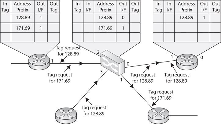
Figure 4-39 MPLS uses tags and tables for routing functions.
Many enterprises today use a switched network in which computers are connected to dedicated ports on Ethernet switches, Gigabit Ethernet switches, ATM switches, and more. This evolution of switches, added services, and the capability to incorporate repeater, bridge, and router functionality have made switches an important part of today’s networking world.
Because security requires control over who can access specific resources, more intelligent devices can provide a higher level of protection because they can make more detail-oriented decisions regarding who can access resources. When devices can look deeper into the packets, they have access to more information to make access decisions, which provides more granular access control.
As previously stated, switching makes it more difficult for intruders to sniff and monitor network traffic because no broadcast and collision information is continually traveling throughout the network. Switches provide a security service that other devices cannot provide. Virtual LANs (VLANs) are an important part of switching networks, because they enable administrators to have more control over their environment and they can isolate users and groups into logical and manageable entities. VLANs are described in the next section.
VLANs
The technology within switches has introduced the capability to use VLANs. VLANs enable administrators to separate and group computers logically based on resource requirements, security, or business needs instead of the standard physical location of the systems. When repeaters, bridges, and routers are used, systems and resources are grouped in a manner dictated by their physical location. Figure 4-40 shows how computers that are physically located next to each other can be grouped logically into different VLANs. Administrators can form these groups based on the users’ and company’s needs instead of the physical location of systems and resources.
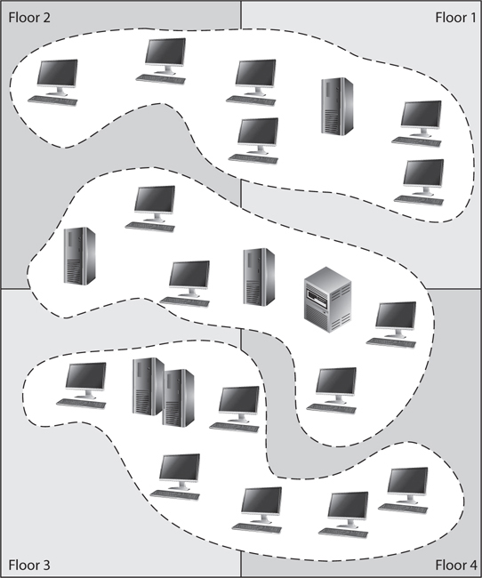
Figure 4-40 VLANs enable administrators to manage logical networks.
An administrator may want to place the computers of all users in the marketing department in the same VLAN network, for example, so all users receive the same broadcast messages and can access the same types of resources. This arrangement could get tricky if a few of the users are located in another building or on another floor, but VLANs provide the administrator with this type of flexibility. VLANs also enable an administrator to apply particular security policies to respective logical groups. This way, if tighter security is required for the payroll department, for example, the administrator can develop a policy, add all payroll systems to a specific VLAN, and apply the security policy only to the payroll VLAN.
A VLAN exists on top of the physical network, as shown in Figure 4-41. If workstation P1 wants to communicate with workstation D1, the message has to be routed—even though the workstations are physically next to each other—because they are on different logical networks.
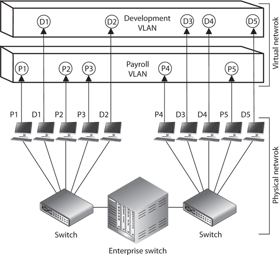
Figure 4-41 VLANs exist on a higher level than the physical network and are not bound to it.
NOTE The IEEE standard that defines how VLANs are to be constructed and how tagging should take place to allow for interoperability is IEEE 802.1Q.
While VLANs are used to segment traffic, attackers can still gain access to traffic that is supposed to be “walled off” in another VLAN segment. VLAN hopping attacks allow attackers to gain access to traffic in various VLAN segments. An attacker can have a system act as though it is a switch. The system understands the tagging values being used in the network and the trunking protocols and can insert itself between other VLAN devices and gain access to the traffic going back and forth. This is called a switch spoofing attack. An attacker can also insert VLAN tags to manipulate the control of traffic at the data link layer in what is known as a double tagging attack. Proper configuration of all switches mitigate VLAN hopping attacks.
Gateways
Gateway is a general term for software running on a device that connects two different environments and that many times acts as a translator for them or somehow restricts their interactions. Usually a gateway is needed when one environment speaks a different language, meaning it uses a certain protocol that the other environment does not understand. The gateway can translate Internetwork Packet Exchange (IPX) protocol packets to IP packets, accept mail from one type of mail server, and format it so another type of mail server can accept and understand it, or it can connect and translate different data link technologies such as FDDI to Ethernet.
Gateways perform much more complex tasks than connection devices such as routers and bridges. However, some people refer to routers as gateways when they connect two unlike networks (Token Ring and Ethernet) because the router has to translate between the data link technologies. Figure 4-42 shows how a network access server (NAS) functions as a gateway between telecommunications and network connections.
Figure 4-42 Several types of gateways can be used in a network. A NAS is one example.
When networks connect to a backbone, a gateway can translate the different technologies and frame formats used on the backbone network versus the connecting LAN protocol frame formats. If a bridge were set up between an FDDI backbone and an Ethernet LAN, the computers on the LAN would not understand the FDDI protocols and frame formats. In this case, a LAN gateway would be needed to translate the protocols used between the different networks.
A popular type of gateway is an electronic mail gateway. Because several e-mail vendors have their own syntax, message format, and way of dealing with message transmission, e-mail gateways are needed to convert messages between e-mail server software. For example, suppose that David, whose corporate network uses Sendmail, writes an e-mail message to Dan, whose corporate network uses Microsoft Exchange. The e-mail gateway will convert the message into a standard that all mail servers understand—usually X.400—and pass it on to Dan’s mail server.
Another example of a gateway is a voice and media gateway. Recently, there has been a drive to combine voice and data networks. This provides for a lot of efficiency because the same medium can be used for both types of data transfers. However, voice is a streaming technology, whereas data is usually transferred in packets. So, this shared medium eventually has to communicate with two different types of networks: the telephone company’s PSTN, and routers that will take the packet-based data off to the Internet. This means that a gateway must separate the combined voice and data information and put it into a form that each of the networks can understand.
Table 4-9 lists the devices covered in this “Networking Devices” section and points out their important characteristics.
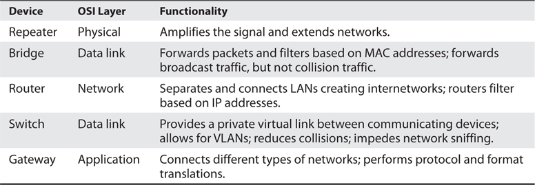
Table 4-9 Network Device Differences
PBXs
Telephone companies use switching technologies to transmit phone calls to their destinations. A telephone company’s central office houses the switches that connect towns, cities, and metropolitan areas through the use of optical fiber rings. So, for example, when Dusty makes a phone call from his house, the call first hits the local central office of the telephone company that provides service to Dusty, and then the switch within that office decides whether it is a local or long-distance call and where it needs to go from there. A Private Branch Exchange (PBX) is a private telephone switch that is located on a company’s property. This switch performs some of the same switching tasks that take place at the telephone company’s central office. The PBX has a dedicated connection to its local telephone company’s central office, where more intelligent switching takes place.
A PBX can interface with several types of devices and provides a number of telephone services. The voice data is multiplexed onto a dedicated line connected to the telephone company’s central office. Figure 4-43 shows how data from different data sources can be placed on one line at the PBX and sent to the telephone company’s switching facility.
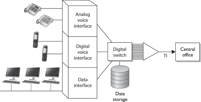
Figure 4-43 A PBX combines different types of data on the same lines.
PBXs use digital switching devices that can control analog and digital signals. Older PBXs may support only analog devices, but most PBXs have been updated to digital. This move to digital systems and signals has reduced a number of the PBX and telephone security vulnerabilities that used to exist. However, that in no way means PBX fraud does not take place today. Many companies, for example, have modems hanging off their PBX (or other transmission access methods) to enable the vendor to dial in and perform maintenance to the system. These modems are usually unprotected doorways into a company’s network. The modem should be activated only when a problem requires the vendor to dial in. It should be disabled otherwise.
In addition, many PBX systems have system administrator passwords that are hardly ever changed. These passwords are set by default; therefore, if 100 companies purchased and implemented 100 PBX systems from the PBX vendor ABC and they do not reset the password, a phreaker (a phone hacker) who knows this default password would now have access to 100 PBX systems. Once a phreaker breaks into a PBX system, she can cause mayhem by rerouting calls, reconfiguring switches, or configuring the system to provide her and her friends with free long-distance calls. This type of fraud happens more often than most companies realize because many companies do not closely watch their phone bills. Though the term is not used as much nowadays, phreakers are very much an issue to our telecommunications systems. Toll fraud (as most of their activities are called) is estimated to cost $1 billion in annual losses worldwide.
PBX systems are also vulnerable to brute force and other types of attacks, in which phreakers use scripts and dictionaries to guess the necessary credentials to gain access to the system. In some cases, phreakers have listened to and changed people’s voice messages. So, for example, when people call to leave Bob a message, they might not hear his usual boring message, but a new message that is screaming obscenities and insults.
NOTE Unfortunately, many security people do not even think about a PBX when they are assessing a network’s vulnerabilities and security level. This is because telecommunication devices have historically been managed by service providers and/or by someone on the staff who understands telephony. The network administrator is usually not the person who manages the PBX, so the PBX system commonly does not even get assessed. The PBX is just a type of switch and it is directly connected to the company’s infrastructure; thus, it is a doorway for the bad guys to exploit and enter. These systems need to be assessed and monitored just like any other network device.
Network Diagramming
In many cases, you cannot capture a full network in a diagram because of the complexity of most organizations’ networks. Sometimes we have a false sense of security when we have a pretty network diagram that we can all look at and be proud of, but let’s dig deeper into why this can be deceiving. From what perspective should you look at a network? There can be a cabling diagram that shows you how everything is physically connected (coaxial, UTP, fiber) and a wireless portion that describes the WLAN structure. There can be a network diagram that illustrates the network in infrastructure layers of access, aggregation, edge, and core. You can have a diagram that illustrates how the various networking routing takes place (VLANs, MPLS connections, OSPF, IGRP, and BGP links). You can have a diagram that shows you how different data flows take place (FTP, IPSec, HTTP, TLS, L2TP, PPP, Ethernet, FDDI, ATM, etc.). You can have a diagram that separates workstations and the core server types that almost every network uses (DNS, DHCP, web farm, storage, print, SQL, PKI, mail, domain controllers, RADIUS, etc.). You can look at a network based upon trust zones, which are enforced by filtering routers, firewalls, and DMZ structures. You can look at a network based upon its IP subnet structure. But what if you look at a network diagram from a Microsoft perspective, which illustrates many of these things but in forest, tree, domain, and OU containers? Then you need to show remote access connections, VPN concentrators, extranets, and the various MAN and WAN connections. How do we illustrate our IP telephony structure? How do we integrate our mobile device administration servers into the diagram? How do we document our new cloud computing infrastructure? How do we show the layers of virtualization within our database? How are redundant lines and fault-tolerance solutions marked? How does this network correlate and interact with our offsite location that carries out parallel processing? And we have not even gotten to our security components (firewalls, IDS, IPS, DLP, antimalware, content filters, etc.). And in the real world whatever network diagrams a company does have are usually out of date because they take a lot of effort to create and maintain.
The point is that a network is a complex beast that cannot really be captured on one piece of paper. Compare it to a human body. When you go into the doctor’s office you see posters on the wall. One poster shows the circulatory system, one shows the muscles, one shows bones, another shows organs, another shows tendons and ligaments; a dentist office has a bunch of posters on teeth; if you are at an acupuncture clinic, there will be a poster on acupuncture and reflexology points. And then there is a ton of stuff no one makes posters for: hair follicles, skin, toenails, eyebrows, but these are all part of one system.
So what does this mean to the security professional? You have to understand a network from many different aspects if you are actually going to secure it. You start by learning all this network stuff in a modular fashion, but you need to quickly understand how it all works together under the covers. You can be a complete genius on how everything works within your current environment but not fully understand that when an employee connects her iPhone to her company laptop that is connected to the corporate network and uses it as a modem, this is an unmonitored WAN connection that can be used as a doorway by an attacker. Security is complex and demanding, so do not ever get too cocky, and always remember that a diagram is just showing a perspective of a network, not the whole network.
Firewalls
Firewalls are used to restrict access to one network from another network. Most companies use firewalls to restrict access to their networks from the Internet. They may also use firewalls to restrict one internal network segment from accessing another internal segment. For example, if the security administrator wants to make sure employees cannot access the research and development network, he would place a firewall between this network and all other networks and configure the firewall to allow only the type of traffic he deems acceptable.
A firewall device supports and enforces the company’s network security policy. An organizational security policy provides high-level directives on acceptable and unacceptable actions as they pertain to protecting critical assets. The firewall has a more defined and granular security policy that dictates what services are allowed to be accessed, what IP addresses and ranges are to be restricted, and what ports can be accessed. The firewall is described as a “choke point” in the network because all communication should flow through it, and this is where traffic is inspected and restricted.
A firewall may be a server running a firewall software product or a specialized hardware appliance. It monitors packets coming into and out of the network it is protecting. It can discard packets, repackage them, or redirect them, depending upon the firewall configuration. Packets are filtered based on their source and destination addresses, and ports by service, packet type, protocol type, header information, sequence bits, and much more. Many times, companies set up firewalls to construct a demilitarized zone (DMZ), which is a network segment located between the protected and unprotected networks. The DMZ provides a buffer zone between the dangerous Internet and the goodies within the internal network that the company is trying to protect. As shown in Figure 4-44, two firewalls are usually installed to form the DMZ. The DMZ usually contains web, mail, and DNS servers, which must be hardened systems because they would be the first in line for attacks. Many DMZs also have an IDS sensor that listens for malicious and suspicious behavior.
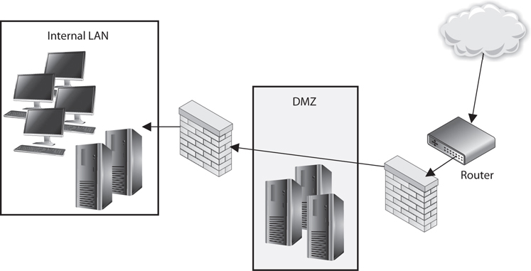
Figure 4-44 At least two firewalls, or firewall interfaces, are generally used to construct a DMZ.
Many different types of firewalls are available, because each environment may have unique requirements and security goals. Firewalls have gone through an evolution of their own and have grown in sophistication and functionality. The following sections describe the various types of firewalls.
The types of firewalls we will review are
• Packet filtering
• Stateful
• Proxy
• Dynamic packet filtering
• Kernel proxy
We will then dive into the three main firewall architectures, which are
• Screened host
• Multihome
• Screened subnet
Packet-Filtering Firewalls
Packet filtering is a firewall technology that makes access decisions based upon network-level protocol header values. The device that is carrying out packet-filtering processes is configured with ACLs, which dictate the type of traffic that is allowed into and out of specific networks.
Packet filtering was the first generation of firewalls, and it is the most rudimentary type of all of the firewall technologies. The filters only have the capability of reviewing protocol header information at the network and transport layers and carrying out permit or deny actions on individual packets. This means the filters can make access decisions based upon the following basic criteria:
• Source and destination IP addresses
• Source and destination port numbers
• Protocol types
• Inbound and outbound traffic direction
Packet filtering is built into a majority of the firewall products today and is a capability that many routers perform. The ACL filtering rules are enforced at the network interface of the device, which is the doorway into or out of a network. As an analogy, you could have a list of items you look for before allowing someone into your office premises through your front door. Your list can indicate that a person must be 18 years or older, have an access badge, and be wearing pants. When someone knocks on the door, you grab your list, which you will use to decide if this person can or cannot come inside. So your front door is one interface into your office premises. You can also have a list that outlines who can exit your office premises through your back door, which is another interface. As shown in Figure 4-45, a router has individual interfaces with their own unique addresses, which provide doorways into and out of a network. Each interface can have its own ACL values, which indicate what type of traffic is allowed in and out of that specific interface.
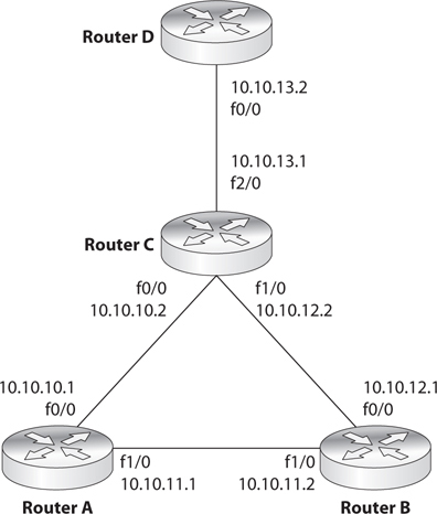
Figure 4-45 ACLs are enforced at the network interface level.
We will cover some basic ACL rules to illustrate how packet filtering is implemented and enforced. The following router configuration allows SMTP traffic to travel from system 10.1.1.2 to system 172.16.1.1:
![]()
This next rule permits UDP traffic from system 10.1.1.2 to 172.16.1.1:
![]()
If you want to ensure that no ICMP traffic enters through a certain interface, the following ACL can be configured and deployed:
![]()
If you want to allow standard web traffic (that is, to a web server listening on port 80) from system 1.1.1.1 to system 5.5.5.5, you can use the following ACL:
![]()
NOTE Filtering inbound traffic is known as ingress filtering. Outgoing traffic can also be filtered using a process referred to as egress filtering.
So when a packet arrives at a packet-filtering device, the device starts at the top of its ACL and compares the packet’s characteristics to each rule set. If a successful match (permit or deny) is found, then the remaining rules are not processed. If no matches are found when the device reaches the end of the list, the traffic should be denied, but each product is different. So if you are configuring a packet-filtering device, make sure that if no matches are identified, then the traffic is denied.
Packet filtering is also known as stateless inspection because the device does not understand the context that the packets are working within. This means that the device does not have the capability to understand the “full picture” of the communication that is taking place between two systems, but can only focus on individual packet characteristics. As we will see in a later section, stateful firewalls understand and keep track of a full communication session, not just the individual packets that make it up. Stateless firewalls make their decisions for each packet based solely on the data contained in that individual packet. Stateful firewalls accumulate data about the packets they see and use that data in an attempt to match incoming and outgoing packets to determine which packets may be part of the same network communications session. By evaluating a packet in the larger context of a network communications session, a stateful firewall has much more complete information than a stateless firewall and can therefore more readily recognize and reject packets that may be part of a network protocol–based attack.
Packet-filtering devices can block many types of attacks at the network protocol level, but they are not effective at protecting against attacks that exploit application-specific vulnerabilities. That is because filtering only examines a packet’s header (i.e., delivery information) and not the data moving between the applications. Thus, a packet-filtering firewall cannot protect against packet content that could, for example, probe for and exploit a buffer overflow in a given piece of software.
The lack of sophistication in packet filtering means that an organization should not solely depend upon this type of firewall to protect its infrastructure and assets, but it does not mean that this technology should not be used at all. Packet filtering is commonly carried out at the edge of a network to strip out all of the obvious “junk” traffic. Since the rules are simple and only header information is analyzed, this type of filtering can take place quickly and efficiently. After traffic is passed through a packet-filtering device, it is usually then processed by a more sophisticated firewall, which digs deeper into the packet contents and can identify application-based attacks.
Some of the weaknesses of packet-filtering firewalls are as follows:
• They cannot prevent attacks that employ application-specific vulnerabilities or functions.
• They have limited logging functionality.
• Most packet-filtering firewalls do not support advanced user authentication schemes.
• Many packet-filtering firewalls cannot detect spoofed addresses.
• They may not be able to detect packet fragmentation attacks.
The advantages to using packet-filtering firewalls are that they are scalable, they are not application dependent, and they have high performance because they do not carry out extensive processing on the packets. They are commonly used as the first line of defense to strip out all the network traffic that is obviously malicious or unintended for a specific network. The network traffic usually then has to be processed by more sophisticated firewalls that will identify the not-so-obvious security risks.
Stateful Firewalls
When packet filtering is used, a packet arrives at the firewall, and it runs through its ACLs to determine whether this packet should be allowed or denied. If the packet is allowed, it is passed on to the destination host, or to another network device, and the packet-filtering device forgets about the packet. This is different from stateful inspection, which remembers and keeps track of what packets went where until each particular connection is closed.
A stateful firewall is like a nosy neighbor who gets into people’s business and conversations. She keeps track of the suspicious cars that come into the neighborhood, who is out of town for the week, and the postman who stays a little too long at the neighbor lady’s house. This can be annoying until your house is burglarized. Then you and the police will want to talk to the nosy neighbor, because she knows everything going on in the neighborhood and would be the one most likely to know something unusual happened. A stateful-inspection firewall is nosier than a regular filtering device because it keeps track of what computers say to each other. This requires that the firewall maintain a state table, which is like a score sheet of who said what to whom.
Keeping track of the state of a protocol connection requires keeping track of many variables. Most people understand the three-step handshake a TCP connection goes through (SYN, SYN/ACK, ACK), but what does this really mean? If Quincy’s system wants to communicate with your system using TCP, it will send your system a packet and in the TCP header the SYN flag value will be set to 1. This makes this packet a SYN packet. If your system accepts Quincy’s system’s connection request, it will send back a packet that has both the SYN and ACK flags within the packet header set to 1. This is a SYN/ACK packet. While many people know about these three steps of setting up a TCP connection, they are not always familiar with all of the other items that are being negotiated at this time. For example, your system and Quincy’s system will agree upon sequence numbers, how much data to send at a time (window size), how potential transmission errors will be identified (CRC values), etc. Figure 4-46 shows all of the values that make up a TCP header. So there is a lot of information going back and forth between your systems just in this one protocol—TCP. There are other protocols that are involved with networking that a stateful firewall has to be aware of and keep track of.
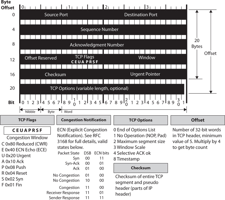
Figure 4-46 TCP header
So “keeping state of a connection” means to keep a scorecard of all the various protocol header values as packets go back and forth between systems. The values not only have to be correct—they have to happen in the right sequence. For example, if a stateful firewall receives a packet that has all TCP flag values turned to 1, something malicious is taking place. Under no circumstances during a legitimate TCP connection should all of these values be turned on like this. Attackers send packets with all of these values turned to 1 with the hopes that the firewall does not understand or check these values and just forwards the packets onto the target system.
In another situation, if Gwen’s system sends your system a SYN/ACK packet and your system did not first send a SYN packet to Gwen’s system, this, too, is against the protocol rules. The protocol communication steps have to follow the proper sequence. Attackers send SYN/ACK packets to target systems hoping that the firewall interprets this as an already established connection and just allows the packets to go to the destination system without inspection. A stateful firewall will not be fooled by such actions because it keeps track of each step of the communication. It knows how protocols are supposed to work, and if something is out of order (incorrect flag values, incorrect sequence, etc.), it does not allow the traffic to pass through.
When a connection begins between two systems, the firewall investigates all elements of the packet (all headers, payload, and trailers). All of the necessary information about the specific connection is stored in the state table (source and destination IP addresses, source and destination ports, protocol type, header flags, sequence numbers, timestamps, etc.). Once the initial packets go through this in-depth inspection and everything is deemed safe, the firewall then just reviews the network and transport header portions for the rest of the session. The values of each header for each packet are compared to what is in the current state table, and the table is updated to reflect the progression of the communication process. Scaling down the inspection of the full packet to just the headers for each packet is done to increase performance.
TCP is considered a connection-oriented protocol, and the various steps and states this protocol operates within are very well defined. A connection progresses through a series of states during its lifetime. The states are LISTEN, SYN-SENT, SYN-RECEIVED, ESTABLISHED, FIN-WAIT-1, FIN-WAIT-2, CLOSE-WAIT, CLOSING, LAST-ACK, TIME-WAIT, and the fictional state CLOSED. A stateful firewall keeps track of each of these states for each packet that passes through, along with the corresponding acknowledgment and sequence numbers. If the acknowledgment and/or sequence numbers are out of order, this could imply that a replay attack is underway, and the firewall will protect the internal systems from this activity.
Nothing is ever simple in life, including the standardization of network protocol communication. While the previous statements are true pertaining to the states of a TCP connection, in some situations an application layer protocol has to change these basic steps. For example, FTP uses an unusual communication exchange when initializing its data channel compared to all of the other application layer protocols. FTP basically sets up two sessions just for one communication exchange between two computers. The states of the two individual TCP connections that make up an FTP session can be tracked in the normal fashion, but the state of the FTP connection follows different rules. For a stateful device to be able to properly monitor the traffic of an FTP session, it must be able to take into account the way that FTP uses one outbound connection for the control channel and one inbound connection for the data channel. If you were configuring a stateful firewall, you would need to understand the particulars of some specific protocols to ensure that each is being properly inspected and controlled.
Since TCP is a connection-oriented protocol, it has clearly defined states during the connection establishment, maintenance, and tearing-down stages. UDP is a connectionless protocol, which means that none of these steps take place. UDP holds no state, which makes it harder for a stateful firewall to keep track of. For connectionless protocols, a stateful firewall keeps track of source and destination addresses, UDP header values, and some ACL rules. This connection information is also stored in the state table and tracked. Since the protocol does not have a specific tear-down stage, the firewall will just time out the connection after a period of inactivity and remove the data being kept pertaining to that connection from the state table.
An interesting complexity of stateful firewalls and UDP connections is how ICMP comes into play. Since UDP is connectionless, it does not provide a mechanism to allow the receiving computer to tell the sending computer that data is coming too fast. In TCP, the receiving computer can alter the window value in its header, which tells the sending computer to reduce the amount of data that is being sent. The message is basically, “You are overwhelming me and I cannot process the amount of data you are sending me. Slow down.” UDP does not have a window value in its header, so instead the receiving computer sends an ICMP packet that provides the same function. But now this means that the stateful firewall must keep track of and allow associated ICMP packets with specific UDP connections. If the firewall does not allow the ICMP packets to get to the sending system, the receiving system could get overwhelmed and crash. This is just one example of the complexity that comes into play when a firewall has to do more than just packet filtering. Although stateful inspection provides an extra step of protection, it also adds more complexity because this device must now keep a dynamic state table and remember connections.
Stateful-inspection firewalls unfortunately have been the victims of many types of DoS attacks. Several types of attacks are aimed at flooding the state table with bogus information. The state table is a resource, similar to a system’s hard drive space, memory, and CPU. When the state table is stuffed full of bogus information, a poorly designed device may either freeze or reboot.
Proxy Firewalls
A proxy is a middleman. It intercepts and inspects messages before delivering them to the intended recipients. Suppose you need to give a box and a message to the president of the United States. You couldn’t just walk up to the president and hand over these items. Instead, you would have to go through a middleman, likely the Secret Service, who would accept the box and message and thoroughly inspect the box to ensure nothing dangerous was inside. This is what a proxy firewall does—it accepts messages either entering or leaving a network, inspects them for malicious information, and, when it decides the messages are okay, passes the data on to the destination computer.
A proxy firewall stands between a trusted and untrusted network and makes the connection, each way, on behalf of the source. What is important is that a proxy firewall breaks the communication channel; there is no direct connection between the two communicating devices. Where a packet-filtering device just monitors traffic as it is traversing a network connection, a proxy ends the communication session and restarts it on behalf of the sending system. Figure 4-47 illustrates the steps of a proxy-based firewall. Notice that the firewall is not just applying ACL rules to the traffic, but stops the user connection at the internal interface of the firewall itself and then starts a new session on behalf of this user on the external interface. When the external web server replies to the request, this reply goes to the external interface of the proxy firewall and ends. The proxy firewall examines the reply information and, if it is deemed safe, starts a new session from itself to the internal system. This is just like our analogy of what the delivery man does between you and the president.
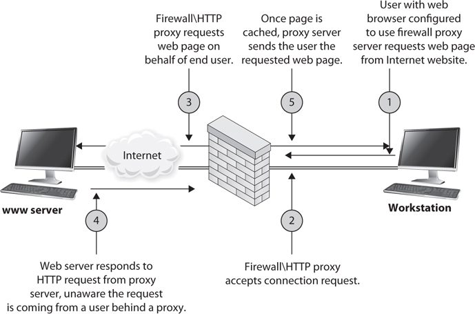
Figure 4-47 Proxy firewall breaks connection
Now a proxy technology can actually work at different layers of a network stack. A proxy-based firewall that works at the lower layers of the OSI model is referred to as a circuit-level proxy. A proxy-based firewall that works at the application layer is, strangely enough, called an application-level proxy.
A circuit-level proxy creates a connection (circuit) between the two communicating systems. It works at the session layer of the OSI model and monitors traffic from a network-based view. This type of proxy cannot “look into” the contents of a packet; thus, it does not carry out deep-packet inspection. It can only make access decisions based upon protocol header and session information that is available to it. While this means that it cannot provide as much protection as an application-level proxy, because it does not have to understand application layer protocols, it is considered application independent. So it cannot provide the detail-oriented protection that a proxy working at a higher level can, but this allows it to provide a broader range of protection where application layer proxies may not be appropriate or available.
NOTE Traffic sent to the receiving computer through a circuit-level proxy appears to have originated from the firewall instead of the sending system. This is useful for hiding information about the internal computers on the network the firewall is protecting.
Application-level proxies inspect the packet up through the application layer. Where a circuit-level proxy only has insight up to the session layer, an application-level proxy understands the packet as a whole and can make access decisions based on the content of the packets. Application-level proxies understand various services and protocols and the commands that are used by them. An application-level proxy can distinguish between an FTP GET command and an FTP PUT command, for example, and make access decisions based on this granular level of information; on the other hand, packet-filtering firewalls and circuit-level proxies can allow or deny FTP requests only as a whole, not by the commands used within FTP.
An application-level proxy firewall has one proxy per protocol. A computer can have many types of protocols (FTP, NTP, SMTP, HTTP, and so on). Thus, one application-level proxy per protocol is required. This does not mean one proxy firewall per service is required, but rather that one portion of the firewall product is dedicated to understanding how a specific protocol works and how to properly filter it for suspicious data.
Providing application-level proxy protection can be a tricky undertaking. The proxy must totally understand how specific protocols work and what commands within that protocol are legitimate. This is a lot to know and look at during the transmission of data. As an analogy, picture a screening station at an airport that is made up of many employees, all with the job of interviewing people before they are allowed into the airport and onto an airplane. These employees have been trained to ask specific questions and detect suspicious answers and activities, and have the skill set and authority to detain suspicious individuals. Now, suppose each of these employees speaks a different language because the people they interview come from different parts of the world. So, one employee who speaks German could not understand and identify suspicious answers of a person from Italy because they do not speak the same language. This is the same for an application-level proxy firewall. Each proxy is a piece of software that has been designed to understand how a specific protocol “talks” and how to identify suspicious data within a transmission using that protocol.
NOTE If the application-level proxy firewall does not understand a certain protocol or service, it cannot protect this type of communication. In this scenario, a circuit-level proxy is useful because it does not deal with such complex issues. An advantage of a circuit-level proxy is that it can handle a wider variety of protocols and services than an application-level proxy can, but the downfall is that the circuit-level proxy cannot provide the degree of granular control that an application-level proxy provides. Life is just full of compromises.
A circuit-level proxy works similarly to a packet filter in that it makes access decisions based on address, port, and protocol type header values. It looks at the data within the packet header rather than the data at the application layer of the packet. It does not know whether the contents within the packet are safe or unsafe; it only understands the traffic from a network-based view.
An application-level proxy, on the other hand, is dedicated to a particular protocol or service. At least one proxy is used per protocol because one proxy could not properly interpret all the commands of all the protocols coming its way. A circuit-level proxy works at a lower layer of the OSI model and does not require one proxy per protocol because it does not look at such detailed information.
SOCKS is an example of a circuit-level proxy gateway that provides a secure channel between two computers. When a SOCKS-enabled client sends a request to access a computer on the Internet, this request actually goes to the network’s SOCKS proxy firewall, as shown in Figure 4-48, which inspects the packets for malicious information and checks its policy rules to see whether this type of connection is allowed. If the packet is acceptable and this type of connection is allowed, the SOCKS firewall sends the message to the destination computer on the Internet. When the computer on the Internet responds, it sends its packets to the SOCKS firewall, which again inspects the data and then passes the packets on to the client computer.
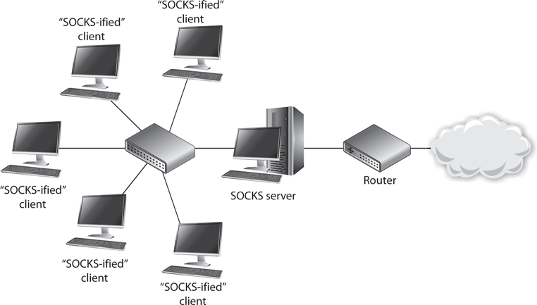
Figure 4-48 Circuit-level proxy firewall
The SOCKS firewall can screen, filter, audit, log, and control data flowing in and out of a protected network. Because of its popularity, many applications and protocols have been configured to work with SOCKS in a manner that takes less configuration on the administrator’s part, and various firewall products have integrated SOCKS software to provide circuit-based protection.
NOTE Remember that whether an application- or circuit-level proxy firewall is being used, it is still acting as a proxy. Both types of proxy firewalls deny actual end-to-end connectivity between the source and destination systems. In attempting a remote connection, the client connects to and communicates with the proxy; the proxy, in turn, establishes a connection to the destination system and makes requests to it on the client’s behalf. The proxy maintains two independent connections for every one network transmission. It essentially turns a two-party session into a four-party session, with the middle process emulating the two real systems.
Dynamic Packet-Filtering Firewalls
When an internal system needs to communicate with an entity outside its trusted network, it must choose a source port so the receiving system knows how to respond properly. Ports up to 1023 are called well-known ports and are reserved for specific server-side services. The sending system must choose a dynamic port higher than 1023 when it sets up a connection with another entity. The dynamic packet-filtering firewall then creates an ACL that allows the external entity to communicate with the internal system via this high-numbered port. If this were not an available option for your dynamic packet-filtering firewall, you would have to allow “punch holes” in your firewalls for all ports above 1023, because the client side chooses these ports dynamically and the firewall would never know exactly on which port to allow or disallow traffic.
NOTE The standard port for HTTP is 80, which means a server will have a service listening on port 80 for HTTP traffic. HTTP (and most other protocols) works in a type of client/server model. The server portion uses the well-known ports (FTP uses 20 and 21; SMTP uses 25) so everyone knows how to connect to those services. A client will not use one of these well-known port numbers for itself, but will choose a random, higher port number.
An internal system could choose a source port of 11,111 for its message to the outside system. This frame goes to the dynamic packet-filtering firewall, which builds an ACL, as illustrated in Figure 4-49, that indicates a response from the destination computer to this internal system’s IP address and port 11,111 is to be allowed. When the destination system sends a response, the firewall allows it. These ACLs are dynamic in nature, so once the connection is finished (either a FIN or RST packet is received), the ACL is removed from the list. On connectionless protocols, such as UDP, the connection times out and then the ACL is removed.
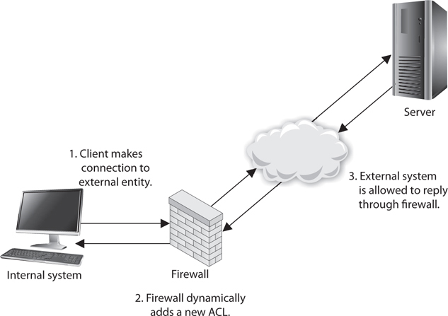
Figure 4-49 Dynamic packet filtering adds ACLs when connections are created.
The benefit of a dynamic packet-filtering firewall is that it gives you the option of allowing any type of traffic outbound and permitting only response traffic inbound.
Kernel Proxy Firewalls
A kernel proxy firewall is considered a fifth-generation firewall. It differs from all the previously discussed firewall technologies because it creates dynamic, customized network stacks when a packet needs to be evaluated.
When a packet arrives at a kernel proxy firewall, a new virtual network stack is created, which is made up of only the protocol proxies necessary to examine this specific packet properly. If it is an FTP packet, then the FTP proxy is loaded in the stack. The packet is scrutinized at every layer of the stack. This means the data link header will be evaluated along with the network header, transport header, session layer information, and the application layer data. If anything is deemed unsafe at any of these layers, the packet is discarded.
Kernel proxy firewalls are faster than application-level proxy firewalls because all of the inspection and processing takes place in the kernel and does not need to be passed up to a higher software layer in the operating system. It is still a proxy-based system, so the connection between the internal and external entity is broken by the proxy acting as a middleman, and it can perform NAT by changing the source address, as do the preceding proxy-based firewalls.
Next-Generation Firewalls
A next-generation firewall (NGFW) combines the best attributes of the previously discussed firewalls, but adds a number of important improvements. Most importantly, it incorporates a signature-based IPS engine. This means that, in addition to ensuring that the traffic is behaving in accordance with the rules of the applicable protocols, the firewall can look for specific indicators of attack even in otherwise well-behaved traffic. Some of the most advanced NGFWs include features that allow them to share signatures with a cloud-based aggregator so that once a new attack is detected by one firewall, all other firewalls manufactured by that vendor become aware of the attack signature.
Another characteristic of an NGFW is its ability to connect to external data sources such as Active Directory, whitelists, blacklists, and policy servers. This features allows controls to be defined in one place and pulled by every NGFW on the network, which reduces the chances of inconsistent settings on the various firewalls that typically exist in large networks.
For all their power, NGFWs are not for everyone. The typical cost of ownership alone tends to make these infeasible for small or even medium-sized networks. Organizations need to ensure that the correct firewall technology is in place to monitor specific network traffic types and protect unique resource types. The firewalls also have to be properly placed; we will cover this topic in the next section.
NOTE Firewall technology has evolved as attack types have evolved. The first-generation firewalls could only monitor network traffic. As attackers moved from just carrying out network-based attacks (DoS, fragmentation, spoofing, etc.) to software-based attacks (buffer overflows, injections, malware, etc.), new generations of firewalls were developed to monitor for these types of attacks.
Table 4-10 lists the important concepts and characteristics of the firewall types discussed in the preceding sections. Although various firewall products can provide a mix of these services and work at different layers of the OSI model, it is important you understand the basic definitions and functionalities of these firewall types.
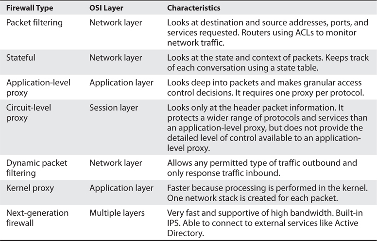
Table 4-10 Comparison of Different Types of Firewalls
Firewall Architecture
Firewalls can be placed in a number of areas on a network to meet particular needs. They can protect an internal network from an external network and act as a choke point for all traffic. A firewall can be used to segment and partition network sections and enforce access controls between two or more subnets. Firewalls can also be used to provide a DMZ architecture. And as covered in the previous section, the right firewall type needs to be placed in the right location. Organizations have common needs for firewalls; hence, they keep them in similar places on their networks. We will see more on this topic in the following sections.
Dual-Homed Firewall Dual-homed refers to a device that has two interfaces: one connected to one network and the other connected to a different network. If firewall software is installed on a dual-homed device—and it usually is—the underlying operating system should have packet forwarding and routing turned off for security reasons. If they are enabled, the computer may not apply the necessary ACLs, rules, or other restrictions required of a firewall. When a packet comes to the external NIC from an untrusted network on a dual-homed firewall and the operating system has forwarding enabled, the operating system will forward the traffic instead of passing it up to the firewall software for inspection.
Many network devices today are multihomed, which just means they have several NICs that are used to connect several different networks. Multihomed devices are commonly used to house firewall software, since the job of a firewall is to control the traffic as it goes from one network to another. A common multihomed firewall architecture allows a company to have several DMZs. One DMZ may hold devices that are shared between companies in an extranet, another DMZ may house the company’s DNS and mail servers, and yet another DMZ may hold the company’s web servers. Different DMZs are used for two reasons: to control the different traffic types (for example, to make sure HTTP traffic only goes toward the web servers and ensure DNS requests go toward the DNS server), and to ensure that if one system on one DMZ is compromised, the other systems in the rest of the DMZs are not accessible to this attacker.
If a company depends solely upon a multihomed firewall with no redundancy, this system could prove to be a single point of failure. If it goes down, then all traffic flow stops. Some firewall products have embedded redundancy or fault-tolerance capabilities. If a company uses a firewall product that does not have these capabilities, then the network should have redundancy built into it.
Along with potentially being a single point of failure, another security issue that should be understood is the lack of defense in depth. If the company depends upon just one firewall, no matter what architecture is being used or how many interfaces the device has, there is only one layer of protection. If an attacker can compromise the one firewall, then she can gain direct access to company network resources.
Screened Host A screened host is a firewall that communicates directly with a perimeter router and the internal network. Figure 4-50 shows this type of architecture.
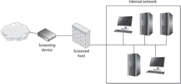
Figure 4-50 A screened host is a firewall that is screened by a router.
Traffic received from the Internet is first filtered via packet filtering on the outer router. The traffic that makes it past this phase is sent to the screened-host firewall, which applies more rules to the traffic and drops the denied packets. Then the traffic moves to the internal destination hosts. The screened host (the firewall) is the only device that receives traffic directly from the router. No traffic goes directly from the Internet, through the router, and to the internal network. The screened host is always part of this equation.
If the firewall is an application-based system, protection is provided at the network layer by the router through packet filtering, and at the application layer by the firewall. This arrangement offers a high degree of security, because for an attacker to be successful, she would have to compromise two systems.
What does the word “screening” mean in this context? As shown in Figure 4-50, the router is a screening device and the firewall is the screened host. This just means there is a layer that scans the traffic and gets rid of a lot of the “junk” before it is directed toward the firewall. A screened host is different from a screened subnet, which is described next.
Screened Subnet A screened-subnet architecture adds another layer of security to the screened-host architecture. The external firewall screens the traffic entering the DMZ network. However, instead of the firewall then redirecting the traffic to the internal network, an interior firewall also filters the traffic. The use of these two physical firewalls creates a DMZ.
In an environment with only a screened host, if an attacker successfully breaks through the firewall, nothing lies in her way to prevent her from having full access to the internal network. In an environment using a screened subnet, the attacker would have to hack through another firewall to gain access. In this layered approach to security, the more layers provided, the better the protection. Figure 4-51 shows a simple example of a screened subnet.
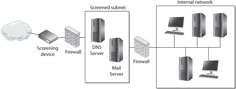
Figure 4-51 With a screened subnet, two firewalls are used to create a DMZ.
The examples shown in the figures are simple in nature. Often, more complex networks and DMZs are implemented in real-world systems. Figures 4-52 and 4-53 show some other possible architectures of screened subnets and their configurations.
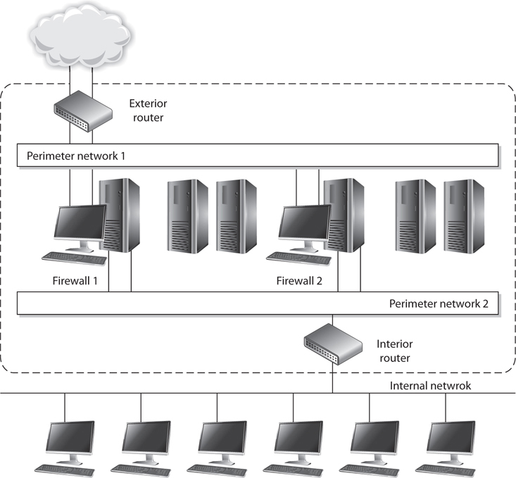
Figure 4-52 A screened subnet can have different networks within it and different firewalls that filter for specific threats.
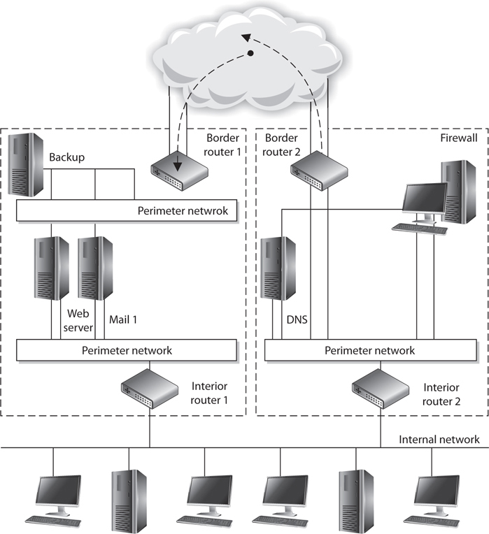
Figure 4-53 Some architectures have separate screened subnets with different server types in each.
The screened-subnet approach provides more protection than a stand-alone firewall or a screened-host firewall because three devices are working together and all three devices must be compromised before an attacker can gain access to the internal network. This architecture also sets up a DMZ between the two firewalls, which functions as a small network isolated among the trusted internal and untrusted external networks. The internal users usually have limited access to the servers within this area. Web, e-mail, and other public servers often are placed within the DMZ. Although this solution provides the highest security, it also is the most complex. Configuration and maintenance can prove to be difficult in this setup, and when new services need to be added, three systems may need to be reconfigured instead of just one.
TIP Sometimes a screened-host architecture is referred to as a single-tiered configuration and a screened subnet is referred to as a two-tiered configuration. If three firewalls create two separate DMZs, this may be called a three-tiered configuration.
Virtualized Firewalls
A lot of the network functionality we have covered up to this point can take place in virtual environments. Most people understand that a host system can have virtual guest systems running on it, enabling multiple operating systems to run on the same hardware platform simultaneously. But the industry has advanced much further than this when it comes to virtualized technology. Routers and switches can be virtualized, which means you do not actually purchase a piece of hardware and plug it into your network, but instead you deploy software products that carry out routing and switching functionality.
We used to deploy a piece of hardware for every network function needed (DNS, mail, routers, switches, storage, Web), but today many of these items run within virtual machines on a smaller number of hardware machines. This reduces software and hardware costs and allows for more centralized administration, but these components still need to be protected from each other and external malicious entities. As an analogy, let’s say that 15 years ago each person lived in their own house and a police officer was placed between each house so that the people in the houses could not attack each other. Then last year, many of these people moved in together so that now at least five people live in the same physical house. These people still need to be protected from each other, so some of the police officers had to be moved inside the houses to enforce the laws and keep the peace. This is the same thing that virtualized firewalls do—they have “moved into” the virtualized environments to provide the necessary protection between virtualized entities.
As illustrated in Figure 4-54, a network can have a traditional physical firewall on the physical network and virtual firewalls within the individual virtual environments.
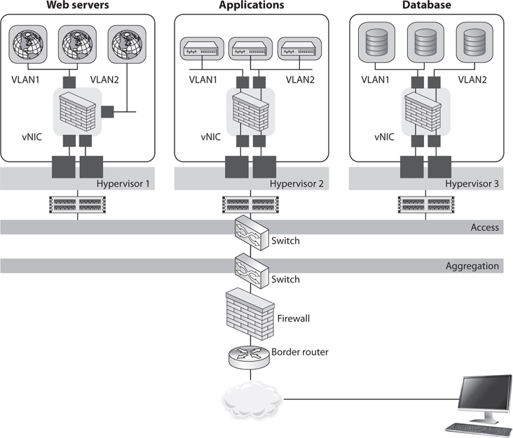
Figure 4-54 Virtual firewalls
Virtual firewalls can provide bridge-type functionality in which individual traffic links are monitored between virtual machines, or they can be integrated within the hypervisor. The hypervisor is the software component that carries out virtual machine management and oversees guest system software execution. If the firewall is embedded within the hypervisor, then it can “see” and monitor all the activities taking place within the system.
The “Shoulds” of Firewalls
The default action of any firewall should be to implicitly deny any packets not explicitly allowed. This means that if no rule states that the packet can be accepted, that packet should be denied, no questions asked. Any packet entering the network that has a source address of an internal host should be denied. Masquerading, or spoofing, is a popular attacking trick in which the attacker modifies a packet header to have the source address of a host inside the network she wants to attack. This packet is spoofed and illegitimate. There is no reason a packet coming from the Internet should have an internal source network address, so the firewall should deny it. The same is true for outbound traffic. No traffic should be allowed to leave a network that does not have an internal source address. If this occurs, it means someone, or some program, on the internal network is spoofing traffic. This is how zombies work—the agents used in distributed DoS (DDoS) attacks. If packets are leaving a network with different source addresses, these packets are spoofed and the network is most likely being used as an accomplice in a DDoS attack.
Firewalls should reassemble fragmented packets before sending them on to their destination. In some types of attacks, the hackers alter the packets and make them seem to be something they are not. When a fragmented packet comes to a firewall, the firewall is seeing only part of the picture. It will make its best guess as to whether this piece of a packet is malicious or not. Because these fragments contain only a part of the full packet, the firewall is making a decision without having all the facts. Once all fragments are allowed through to a host computer, they can be reassembled into malicious packages that can cause a lot of damage. A firewall should accept each fragment, assemble the fragments into a complete packet, and then make an access decision based on the whole packet. The drawback to this, however, is that firewalls that do reassemble packet fragments before allowing them to go on to their destination computer cause traffic delay and more overhead. It is up to the organization to decide whether this configuration is necessary and whether the added traffic delay is acceptable.
Many companies choose to deny network entrance to packets that contain source routing information, which was mentioned earlier. Source routing means the packet decides how to get to its destination, not the routers in between the source and destination computer. Source routing moves a packet throughout a network on a predetermined path. The sending computer must know about the topology of the network and how to route data properly. This is easier for the routers and connection mechanisms in between, because they do not need to make any decisions on how to route the packet. However, it can also pose a security risk. When a router receives a packet that contains source routing information, the router assumes the packet knows what needs to be done and passes the packet on. In some cases, not all filters may be applied to the packet, and a network administrator may want packets to be routed only through a certain path and not the route a particular packet dictates. To make sure none of this misrouting happens, many firewalls are configured to check for source routing information within the packet and deny it if it is present.
Some common firewall rules that should be implemented are as follows:
• Silent rule Drops “noisy” traffic without logging it. This reduces log sizes by not responding to packets that are deemed unimportant.
• Stealth rule Disallows access to firewall software from unauthorized systems.
• Cleanup rule Last rule in rule base, drops and logs any traffic that does not meet preceding rules.
• Negate rule Used instead of the broad and permissive “any rules,” provides tighter permission rights by specifying what system can be accessed and how.
Firewalls are not effective “right out of the box.” You really need to understand the type of firewall being implemented and its configuration ramifications. For example, a firewall may have implied rules, which are used before the rules you configure. These implied rules might contradict your rules and override them. In this case you think a certain traffic type is being restricted, but the firewall may allow that type of traffic into your network by default.
Unfortunately, once a company erects a firewall, it may have a false sense of security. Firewalls are only one piece of the puzzle, and security has a lot of pieces.
The following list addresses some of the issues that need to be understood as they pertain to firewalls:
• Most of the time a distributed approach needs to be used to control all network access points, which cannot happen through the use of just one firewall.
• Firewalls can present a potential bottleneck to the flow of traffic and a single point of failure threat.
• Some firewalls do not provide protection from malware and can be fooled by the more sophisticated attack types.
• Firewalls do not protect against sniffers or rogue wireless access points and provide little protection against insider attacks.
The role of firewalls is becoming more and more complex as they evolve and take on more functionality and responsibility. At times, this complexity works against security professionals because it requires them to understand and properly implement additional functionality. Without an understanding of the different types of firewalls and architectures available, many more security holes can be introduced, which lays out the welcome mat for attackers.
Proxy Servers
Earlier we covered two types of proxy-based firewalls, which are different from proxy servers. Proxy servers act as an intermediary between the clients that want access to certain services and the servers that provide those services. As a security administrator, you do not want internal systems to directly connect to external servers without some type of control taking place. For example, if users on your network could connect directly to websites without some type of filtering and rules in place, the users could allow malicious traffic into the network or could surf websites your company deems inappropriate. In this situation, all internal web browsers would be configured to send their web requests to a web proxy server. The proxy server validates that the request is safe and then sends an independent request to the website on behalf of the user. A very basic proxy server architecture is shown in Figure 4-55.
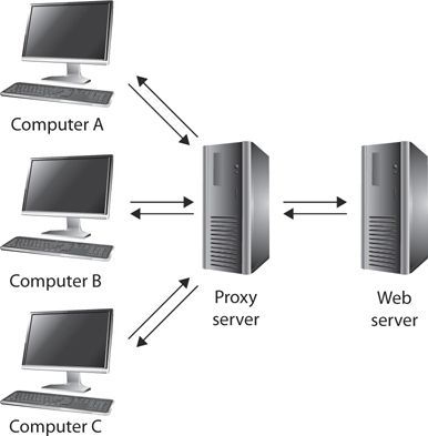
Figure 4-55 Proxy servers control traffic between clients and servers.
The proxy server may cache the response it receives from the server so that when other clients make the same request, a connection does not have to go out to the actual web server again, but the necessary data is served up directly from the proxy server. This drastically reduces latency and allows the clients to get the data they need much more quickly.
There are different types of proxies that provide specific services. A forwarding proxy is one that allows the client to specify the server it wants to communicate with, as in our scenario earlier. An open proxy is a forwarding proxy that is open for anyone to use. An anonymous open proxy allows users to conceal their IP address while browsing websites or using other Internet services. A reverse proxy appears to the clients as the original server. The client sends a request to what it thinks is the original server, but in reality this reverse proxy makes a request to the actual server and provides the client with the response. The forwarding and reverse proxy functionality seems similar, but as Figure 4-56 illustrates, a forwarding proxy server is commonly on an internal network controlling traffic that is exiting the network. A reverse proxy server is commonly on the network that fulfills clients’ requests; thus, it is handling traffic that is entering its network. The reverse proxy can carry out load balancing, encryption acceleration, security, and caching.
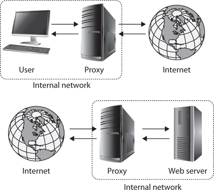
Figure 4-56 Forward vs. reverse proxy services
Web proxy servers are commonly used to carry out content filtering to ensure that Internet use conforms to the organization’s acceptable-use policy. These types of proxies can block unacceptable web traffic, provide logs with detailed information pertaining to the websites specific users visited, monitor bandwidth usage statistics, block restricted website usage, and screen traffic for specific keywords (e.g., porn, confidential, Social Security numbers). The proxy servers can be configured to act mainly as caching servers, which keep local copies of frequently requested resources, allowing organizations to significantly reduce their upstream bandwidth usage and costs while significantly increasing performance.
While it is most common to use proxy servers for web-based traffic, they can be used for other network functionality and capabilities, as in DNS proxy servers. Proxy servers are a critical component of almost every network today. They need to be properly placed, configured, and monitored.
NOTE The use of proxy servers to allow for online anonymity has increased over the years. Some people use a proxy server to protect their browsing behaviors from others, with the goal of providing personal freedom and privacy. Attackers use the same functionality to help ensure their activities cannot be tracked back to their local systems.
Honeypot
A honeypot is a computer that is intended to be exploited by attackers, with the administrator’s goal being to gain information on the attack tactics, techniques, and procedures. A honeypot usually sits in the screened subnet, or DMZ, and attempts to lure attackers to it instead of to actual production computers. To make a honeypot system alluring to attackers, administrators may enable services and ports that are popular to exploit. Some honeypot systems emulate services, meaning the actual services are not running but software that acts like those services is available. Honeypot systems can get an attacker’s attention by advertising themselves as easy targets to compromise. They are configured to look like regular company systems so that attackers will be drawn to them like bears are to honey.
Honeypots can work as early detection mechanisms, meaning that the network staff can be alerted that an intruder is attacking a honeypot system, and they can quickly go into action to make sure no production systems are vulnerable to that specific attack type. If two or more honeypot systems are used together, this is referred to as a honeynet.
Organizations use these systems to identify, quantify, and qualify specific traffic types to help determine their danger levels. The systems can gather network traffic statistics and return them to a centralized location for better analysis. So as the systems are being attacked, they gather intelligence information that can help the network staff better understand what is taking place within their environment.
It is important to make sure that the honeypot systems are not connected to production systems and do not provide any “jumping off” points for the attacker. There have been instances where companies improperly implemented honeypots and they were exploited by attackers, who were then able to move from those systems to the company’s internal systems. The honeypots need to be properly segmented from any other live systems on the network.
On a smaller scale, companies may choose to implement tarpits, which are similar to honeypots in that they appear to be easy targets for exploitation. A tarpit can be configured to appear as a vulnerable service that attackers will commonly attempt to exploit. Once the attackers start to send packets to this “service,” the connection to the victim system seems to be live and ongoing, but the response from the victim system is slow and the connection may time out. Most attacks and scanning activities take place through automated tools that require quick responses from their victim systems. If the victim systems do not reply or are very slow to reply, the automated tools may not be successful because the protocol connection times out.
Unified Threat Management
It can be very challenging to manage the long laundry list of security solutions almost every network needs to have in place. The list includes, but is not limited to, firewalls, antimalware, antispam, IDS/IPS, content filtering, data leak prevention, VPN capabilities, and continuous monitoring and reporting. Unified threat management (UTM) appliance products have been developed that provide all (or many) of these functionalities in a single network appliance. The goals of UTM are simplicity, streamlined installation and maintenance, centralized control, and the ability to understand a network’s security from a holistic point of view. Figure 4-57 illustrates how all of these security functions are applied to traffic as it enters this type of dedicated device.
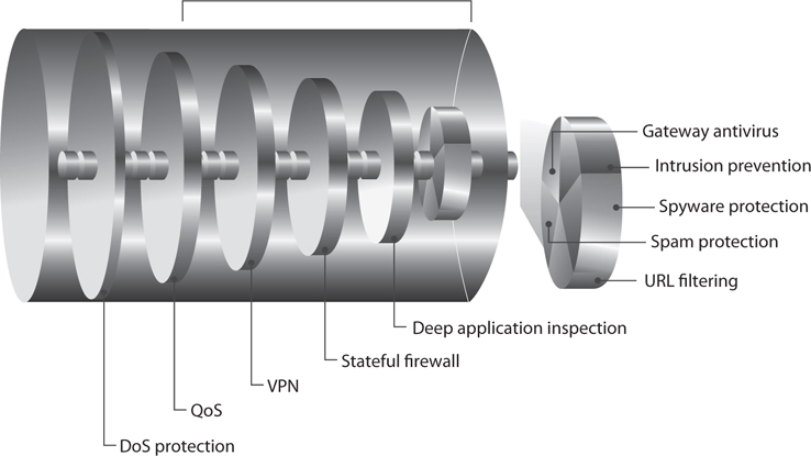
Figure 4-57 Unified threat management
These products are considered all-in-one devices, and the actual type of functionality that is provided varies between vendors. Some products may be able to carry out this type of security for wired, wireless, and Voice over Internet Protocol (VoIP) types of traffic.
Some issues with implementing UTM products are
• Single point of failure for traffic Some type of redundancy should be put into place.
• Single point of compromise If the UTM is successfully hacked, there may not be other layers deployed for protection.
• Performance issues Latency and bandwidth issues can arise since this is a “choke point” device that requires a lot of processing.
Content Distribution Networks
So far, our discussion of networking has sort of implied that there is a (singular) web server, a (singular) database server, and so on. While this simplifies our discussion of network foundations, protocols, and services, we all know that this is a very rare scenario in all but the smallest networks. Instead, we tend to implement multiples of each service, whether to segment systems, provide redundancy, or both. We may have a couple of web servers connected by a load balancer and interfacing with multiple back-end database servers. This sort of redundant deployment can improve performance, but all clients still have to reach the same physical location regardless of where in the world they may be. Wouldn’t it be nice if users in Europe did not have to ride transatlantic cables or satellite links to reach a server in the United States and instead could use one closer to them?
A content distribution network (CDN) consists of multiple servers distributed across a large region, each of which provides content that is optimized for users closest to it. This optimization can come in many flavors. For example, if you were a large video distribution entity like Netflix, you would want to keep your movie files from having to traverse multiple links between routers, since each hop would incur a delay and potential loss of packets (which could cause jitter in the video). Reducing the number of network hops for your video packets would also usually mean having a server geographically closer to the other node, offering you the opportunity to tailor the content for users in that part of the world. Building on our video example, you could keep movies dubbed in Chinese on servers that are on or closer to Asia and those dubbed in French closer to Europe. So when we talk about optimizing content, we can mean many things.
Another benefit of using CDNs is that they make your Internet presence more resistant to DDoS attacks. We will get into detail on these attacks later in this chapter, but for now you should keep in mind that they rely on having a large number of computers flood a server until it becomes unresponsive to legitimate requests. If an attacker can muster a DDoS attack that can send a million packets per second (admittedly fairly small by today’s standards) and aim it at a single server, then it could very well be effective. However, if the attacker tries that against a server that is part of a CDN, the clients will simply start sending their requests to other servers in the network. If the attacker then directs a portion of his attack stream to each server on the CDN in hopes of bringing the whole thing down, the attack will obviously be diffused and would likely require many times more packets. Unsurprisingly, CDNs are how many organizations protect themselves against DDoS attacks.
Software Defined Networking
Software-defined networking (SDN) is an approach to networking that relies on distributed software to provide unprecedented agility and efficiency. Using SDN, it becomes much easier to dynamically route traffic to and from newly provisioned services and platforms. This means a new server can be quickly provisioned using a cloud service provider in response to a spike in service requests and the underlying network can just as quickly adapt to the new traffic patterns. It also means that a service or platform can be quickly moved from one location to another and the SDN will just as quickly update traffic flow rules in response to this change. Unsurprisingly, the three biggest drivers to the adoption of SDN are the growth in cloud computing, big data, and mobile computing.
How does SDN differ from traditional networking? Whereas traditional networking relies on network devices that coordinate with one another in a mostly decentralized manner, SDN centralizes the configuration and control of devices. In a decentralized environment, it takes time for routers to converge onto (or agree on) good routes. These devices must normally be manually configured whenever any changes take place, which is also a time-consuming task. In SDN, on the other hand, all changes are pushed out to the devices either reactively (i.e., in response to requests from the devices) or proactively (i.e., because the admins know a change is being made, such as the addition of 100 servers). Because it is centrally controlled, the SDN approach allows traffic to be routed much more efficiently and securely. Perhaps the most important element of SDN is the abstraction of control and forwarding planes.
Control and Forwarding Planes
The control plane is where the internetwork routing decisions are being made. Think of this as the part of your router that runs the routing protocol (e.g., OSPF). (The analogy is not perfect, but it is useful for now.) This part is responsible for discovering the topology of neighboring networks and maintaining a table of routes for outbound packets. Since most networks are pretty dynamic places in which congestion along different routes is always changing, the control plane is a pretty dynamic place as well. New routes are routinely being discovered, just as old routes are dropped or at least flagged as slow or expensive. As you can see, the control plane is mostly interested in effects that are more than one hop away.
The forwarding plane, by contrast, is where traffic forwarding decisions are made. Think of this as that part of your router that decides (very quickly) that a packet received on network interface eth0 needs to be forwarded to network interface eth3. How does the forwarding plane decide this? By using the products developed by the control plane. The control plane is the strategic, methodical planner of traffic routing, while the forwarding plane is the tactical, fast executioner of those plans. Unsurprisingly, the forwarding plane is typically implemented in hardware such an application-specific integrated chip (ASIC).
NOTE Because traditional routing decisions are made by the controller in an SDN architecture, the networking devices behave (and are referred to) as switches.
In a traditional network architecture, each networking device has its own control plane and its own forwarding plane, both of which run on some sort of proprietary operating system (e.g., Cisco IOS). The normal way of reconfiguring these traditional devices is via a terminal connection of some sort. This means that an administrator must remotely log into each device in order to change its configuration. Let’s suppose that we want to support a distinct QoS for a new user. In order to do this, we’d modify the configuration in each networking device that would be involved in providing services to this user. Even assuming that we are able to do this without making any mistakes, we still face the onerous task of manually changing these parameters whenever the terms of the contract change, or when equipment is replaced or upgraded, or when the network architecture changes. There are exceptions to these challenges, of course, but the point is that making frequent, granular configuration changes is tough.
In SDN, by contrast, the control plane is implemented in a central node that is responsible for managing all the devices in the network. For redundancy and efficiency, this node can actually be a federation of nodes that coordinate their activities with one another. The network devices are then left to do what they do best: forward packets very efficiently. So the forwarding plane lives in the network devices and the control plane lives in a centralized SDN controller. This allows us to abstract the network devices (heterogeneous or otherwise) from the applications that rely on them to communicate in much the same way Windows abstracts the hardware details from the applications running on a workstation.
Approaches to SDN
The concept of network abstraction is central to all implementations of SDN. The manner in which this abstraction is implemented, however, varies significantly among flavors of SDN. There are at least three common approaches to SDN, each championed by a different community and delivered primarily through a specific technology:
• Open The SDN approach championed by the Open Networking Foundation (ONF) (https://www.opennetworking.org) is, by most accounts, the most common. It relies on open-source code and standards to develop the building blocks of an SDN solution. The controller communicates with the switches using OpenFlow. OpenFlow is a standardized, open-source communications interface between controllers and networking devices in an SDN architecture. It allows the devices implementing the forwarding plane to provide information (such as utilization data) to the controller, while allowing the controller to update the flow tables (akin to traditional routing tables) on the devices. Applications communicate with the controller using the RESTful or Java APIs.
• API Another approach to SDN, and one that is championed by Cisco, is built on the premise that OpenFlow is not sufficient to fully leverage the promise of SDN in the enterprise. In addition to OpenFlow, this approach leverages a rich API on proprietary switches that allows greater control over traffic in an SDN. Among the perceived shortcomings that are corrected are the inability of OpenFlow to do deep packet inspection and manipulation, and its reliance on a centralized control plane. This proprietary API approach to SDN is seen as enriching rather than replacing ONF’s SDN approach.
• Overlays Finally, one can imagine a virtualized network architecture as an overlay on a traditional one. In this approach, we virtualize all network nodes, including switches, routers, and servers, and treat them independently of the physical networks upon which this virtualized infrastructure exists. The SDN exists simply as a virtual overlay on top of a physical (underlay) network.
Intranets and Extranets
Web technologies and their uses have exploded with functionality, capability, and popularity. Companies set up internal websites for centralized business information such as employee phone numbers, policies, events, news, and operations instructions. Many companies have also implemented web-based terminals that enable employees to perform their daily tasks, access centralized databases, make transactions, collaborate on projects, access global calendars, use videoconferencing tools and whiteboard applications, and obtain often-used technical or marketing data.
Web-based clients are different from workstations that log into a network and have their own desktop. Web-based clients limit a user’s ability to access the computer’s system files, resources, and hard drive space; access back-end systems; and perform other tasks. The web-based client can be configured to provide a GUI with only the buttons, fields, and pages necessary for the users to perform tasks. This gives all users a standard universal interface with similar capabilities.
When a company uses web-based technologies that are only available inside its networks, it is using an intranet, a “private” network. The company has web servers and client machines using web browsers, and it uses the TCP/IP protocol suite. The web pages are written in HTML or XML (eXtensible Markup Language) and are accessed via HTTP.
Using web-based technologies has many pluses. They have been around for quite some time, they are easy to implement, no major interoperability issues occur, and with just the click of a link, a user can be taken to the location of the requested resource. Web-based technologies are not platform dependent, meaning all websites and pages may be maintained on various platforms and different flavors of client workstations can access them—they only need a web browser.
An extranet extends outside the bounds of the company’s network to enable two or more companies to share common information and resources. Business partners commonly set up extranets to accommodate business-to-business communication. An extranet enables business partners to work on projects together; share marketing information; communicate and work collaboratively on issues; post orders; and share catalogs, pricing structures, and information on upcoming events. Trading partners often use electronic data interchange (EDI), which provides structure and organization to electronic documents, orders, invoices, purchase orders, and a data flow. EDI has evolved into web-based technologies to provide easy access and easier methods of communication.
For many businesses, an extranet can create a weakness or hole in their security if the extranet is not implemented and maintained properly. Properly configured firewalls need to be in place to control who can use the extranet communication channels. Extranets used to be based mainly on dedicated transmission lines, which are more difficult for attackers to infiltrate, but today many extranets are set up over the Internet, which requires properly configured VPNs and security policies.
Many different types of companies use EDI for internal communication and for communication with other companies. A very common implementation is between a company and its supplier. For example, some supplier companies provide inventory to many different companies, such as Target, Wal-Mart, and Kmart. Many of these supplies are made in China and then shipped to a warehouse somewhere in a specific country, as in the United States. When Wal-Mart needs to order more inventory, it sends its request through an EDI network, which is basically an electronic form of our paper-based world. Instead of using paper purchase orders, receipts, and forms, EDI provides all of this digitally.
A value-added network (VAN) is an EDI infrastructure developed and maintained by a service bureau. A Wal-Mart store tracks its inventory by having employees scan bar codes on individual items. When the inventory of an item becomes low, a Wal-Mart system sends a request for more of that specific item. This request goes to a VAN that Wal-Mart pays to use, and the request is then pushed out to a supplier that provides this type of inventory for Wal-Mart. Because Wal-Mart (and other stores) deals with thousands of suppliers, using a VAN simplifies the ordering process: instead of an employee having to track down the right supplier and submit a purchase order, this all happens in the background through an automated EDI network, which is managed by a VAN company for use by other companies.
EDI is moving away from proprietary VAN EDI structures to standardized communication structures to allow more interoperability and easier maintenance. This means that XML, SOAP (Simple Object Access Protocol), and web services are being used. These are the communication structures used in supply chain infrastructures, as illustrated here.
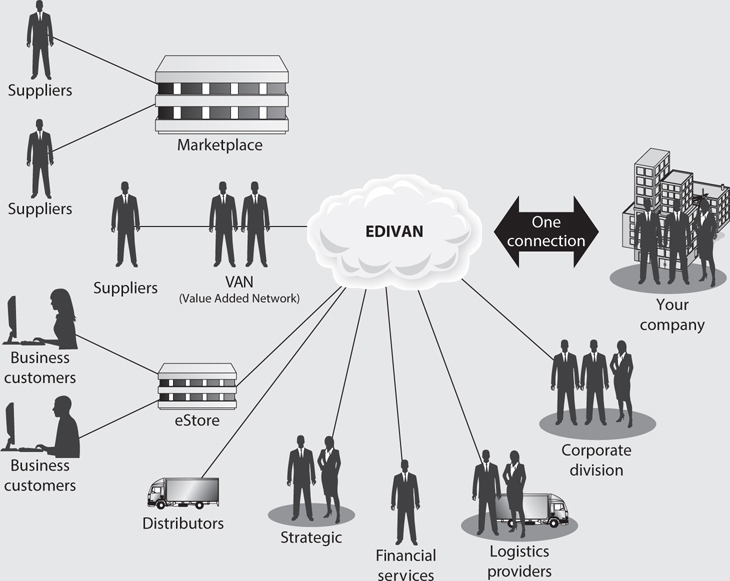
Metropolitan Area Networks
A metropolitan area network (MAN) is usually a backbone that connects LANs to each other and LANs to WANs, the Internet, and telecommunications and cable networks. A majority of today’s MANs are Synchronous Optical Networks (SONETs) or FDDI rings and Metro Ethernet provided by the telecommunications service providers. (FDDI technology was discussed earlier in the chapter.) The SONET and FDDI rings cover a large area, and businesses can connect to the rings via T1, fractional T1, and T3 lines. Figure 4-58 illustrates two companies connected via a SONET ring and the devices usually necessary to make this type of communication possible. This is a simplified example of a MAN. In reality, several businesses are usually connected to one ring.
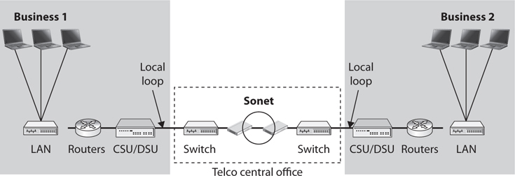
Figure 4-58 A MAN covers a large area and enables businesses to connect to each other, to the Internet, or to other WAN connections.
SONET is a standard for telecommunications transmissions over fiber-optic cables. Carriers and telephone companies have deployed SONET networks for North America, and if they follow the SONET standards properly, these various networks can intercommunicate with little difficulty.
SONET is self-healing, meaning that if a break in the line occurs, it can use a backup redundant ring to ensure transmission continues. All SONET lines and rings are fully redundant. The redundant line waits in the wings in case anything happens to the primary ring.
SONET networks can transmit voice, video, and data over optical networks. Slower-speed SONET networks often feed into larger, faster SONET networks, as shown in Figure 4-59. This enables businesses in different cities and regions to communicate.
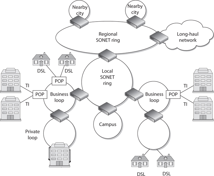
Figure 4-59 Smaller SONET rings connect to larger SONET rings to construct individual MANs.
MANs can be made up of wireless infrastructures, optical fiber, or Ethernet connections. Ethernet has evolved from just being a LAN technology to being used in MAN environments. Due to its prevalent use within organizations’ networks, it is easily extended and interfaced into MAN networks. A service provider commonly uses layer 2 and 3 switches to connect optical fibers, which can be constructed in a ring, star, or partial mesh topology.
VLANs are commonly implemented to differentiate between the various logical network connections that run over the same physical network connection. The VLANs allow for the isolation of the different customers’ traffic from each other and from the core network internal signaling traffic.
Metro Ethernet
Ethernet has been around for many years and embedded in almost every LAN. Ethernet LANs can connect to previously mentioned MAN technologies, or they can be extended to cover a metropolitan area, which is called Metro Ethernet.
Ethernet on the MAN can be used as pure Ethernet or Ethernet integrated with other networking technologies, as in Multiprotocol Label Switching (MPLS). Pure Ethernet is less expensive but less reliable and scalable. MPLS-based deployments are more expensive but highly reliable and scalable, and are typically used by large service providers.
MAN architectures are commonly built upon the following layers: access, aggregation/distribution, metro, and core, as illustrated in Figure 4-60.
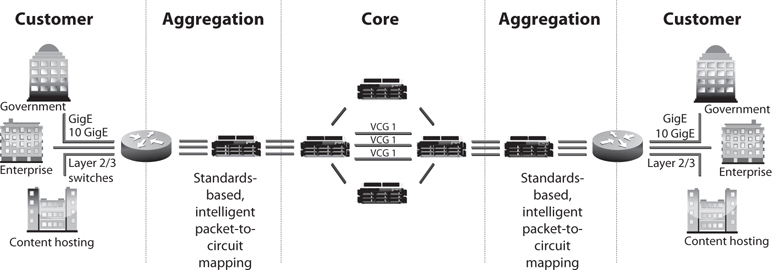
Figure 4-60 MAN architecture
Access devices exist at a customer’s premises and connect the customer’s equipment to the service provider’s network. The service provider’s distribution network aggregates the traffic and sends it to the provider’s core network. From there, the traffic is moved to the next aggregation network that is closest to the destination. This is similar to how smaller highways are connected to larger interstates with on and off ramps that allow people to quickly travel from one location to a different one.
NOTE A Virtual Private LAN Service (VPLS) is a multipoint, layer 2 VPN that connects two or more customer devices using Ethernet bridging techniques. In other words, VPLS emulates a LAN over a managed IP/MPLS network.
Wide Area Networks
LAN technologies provide communication capabilities over a small geographic area, whereas wide area network (WAN) technologies are used when communication needs to travel over a larger geographical area. LAN technologies encompass how a computer puts its data onto a network cable, the rules and protocols of how that data is formatted and transmitted, how errors are handled, and how the destination computer picks up this data from the cable. When a computer on one network needs to communicate with a network on the other side of the country or in a different country altogether, WAN technologies kick in.
The network must have some avenue to other networks, which is most likely a router that communicates with the company’s service provider’s switches or telephone company facilities. Just as several types of technologies lie within the LAN arena, several technologies lie within the WAN arena. This section touches on many of these WAN technologies.
Telecommunications Evolution
Telephone systems have been around for about 100 years, and they started as copper-based analog systems. Central switching offices connected individual telephones manually (via human operators) at first, and later by using electronic switching equipment. After two telephones were connected, they had an end-to-end connection (end-to-end circuit). Multiple phone calls were divided up and placed on the same wire, which is called multiplexing. Multiplexing is a method of combining multiple channels of data over a single transmission path. The transmission is so fast and efficient that the ends do not realize they are sharing a line with many other entities. They think they have the line all to themselves.
In the mid-1960s, digital phone systems emerged with T1 trunks, which carried 24 voice communication calls over two pairs of copper wires. This provided a 1.544-Mbps transmission rate, which brought quicker service, but also the capability to put more multiplexed calls on one wire. When calls take place between switching offices (say, local phone calls), they are multiplexed on trunks such as T1 lines. When more bandwidth is needed, the trunks can be implemented on T3 lines, which can carry up to 28 T1 lines.
The next entity to join the telecommunications party was fiber optics, which enabled even more calls to be multiplexed on one trunk line over longer distances. Then came optical carrier technologies such as SONET, which is a standard for telecommunications transmission over fiber-optic cables. This standard sets up the necessary parameters for transporting digital information over optical systems. Telecommunications carriers used this technology to multiplex lower-speed optical links into higher-speed links, similar to how lower-speed LANs connect to higher-speed WAN links today. Figure 4-61 shows an example of SONET rings connected together and how telecommunications carriers can provide telephone and Internet access to companies and individuals in large areas. The SONET standard enables all carriers to interconnect.
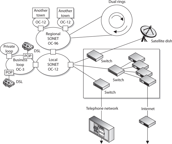
Figure 4-61 SONET technology enables several optical communication loops to communicate.
The next evolutionary step in telecommunications history is Asynchronous Transfer Mode (ATM). ATM encapsulates data in fixed cells and can be used to deliver data over a SONET network. The analogy of a highway and cars is used to describe the SONET and ATM relationship. SONET is the highway that provides the foundation (or network) for the cars—the ATM packets—to travel on.
ATM is a high-speed network technology that is used in WAN implementations by carriers, ISPs, and telephone companies. ATM uses a fixed cell size instead of the variable frame size employed by earlier technologies. This fixed size provides better performance and a reduced overhead for error handling. (More information on ATM technology is provided in the “ATM” section a little later.)
The following is a quick snapshot of telecommunications history:
• Copper lines carry purely analog signals.
• T1 lines carry up to 24 conversations.
• T3 lines carry up to 28 T1 lines.
• Fiber optics and the SONET network.
• ATM over SONET.
SONET was developed in the United States to achieve a data rate around 50 Mbps to support the data flow from T1 lines (1.544 Mbps) and T3 lines (44.736 Mbps). Data travels over these T-carriers as electronic voltage to the edge of the SONET network. Then the voltage must be converted into light to run over the fiber-optic carrier lines, known as optical carrier (OC) lines. Each OC-1 frame runs at a signaling rate of 51.84 Mbps, with a throughput of 44.738 Mbps.
NOTE Optical carrier lines can provide different bandwidth values: OC-1 = 51.84 Mbps, OC-3 = 155.52 Mbps, OC-12 = 622.08 Mbps, and so on.
Europe has a different infrastructure and chose to use Synchronous Digital Hierarchy (SDH), which supports E1 lines (2.048 Mbps) and E3 lines (34.368 Mbps). SONET is the standard for North America, while SDH is the standard for the rest of the world. SDH and SONET are similar but just different enough to be incompatible. For communication to take place between SDH and SONET lines, a gateway must do the proper signaling translation.
You’ve had only a quick glimpse at an amazingly complex giant referred to as telecommunications. Many more technologies are being developed and implemented to increase the amount of data that can be efficiently delivered in a short period of time.
Dedicated Links
A dedicated link is also called a leased line or point-to-point link. It is one single link that is pre-established for the purposes of WAN communications between two destinations. It is dedicated, meaning only the destination points can communicate with each other. This link is not shared by any other entities at any time. This was the main way companies communicated in the past, because not as many choices were available as there are today. Establishing a dedicated link is a good idea for two locations that will communicate often and require fast transmission and a specific bandwidth, but it is expensive compared to other possible technologies that enable several companies to share the same bandwidth and also share the cost. This does not mean that dedicated lines are not in use; they definitely are used, but many other options are now available, including X.25, frame relay, MPLS, and ATM technologies.
T-Carriers
T-carriers are dedicated lines that can carry voice and data information over trunk lines. They were developed by AT&T and were initially implemented in the early 1960s to support pulse-code modulation (PCM) voice transmission. This was first used to digitize the voice over a dedicated, point-to-point, high-capacity connection line. The most commonly used T-carriers are T1 lines and T3 lines. Both are digital circuits that multiplex several individual channels into a higher-speed channel.
These lines can have multiplex functionality through time-division multiplexing (TDM). What does this multiplexing stuff really mean? It means that each channel gets to use the path only during a specific time slot. It’s like having a time-share property on the beach; each co-owner gets to use it, but only one can do so at a time and can only remain for a fixed number of days. Consider a T1 line, which can multiplex up to 24 channels. If a company has a PBX connected to a T1 line, which in turn connects to the telephone company switching office, 24 calls can be chopped up and placed on the T1 line and transferred to the switching office. If this company did not use a T1 line, it would need 24 individual twisted pairs of wire to handle this many calls.
As shown in Figure 4-62, data is input into these 24 channels and transmitted. Each channel gets to insert up to 8 bits into its established time slot. Twenty-four of these 8-bit time slots make up a T1 frame. That does not sound like much information, but 8,000 frames are built per second. Because this happens so quickly, the receiving end does not notice a delay and does not know it is sharing its connection and bandwidth with up to 23 other devices.
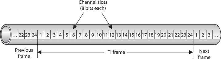
Figure 4-62 Multiplexing puts several phone calls, or data transmissions, on the same wire.
Originally, T1 and T3 lines were used by the carrier companies, but they have been replaced mainly with optical lines. Now T1 and T3 lines feed data into these powerful and super-fast optical lines. The T1 and T3 lines are leased to companies and ISPs that need high-capacity transmission capability. Sometimes, T1 channels are split up between companies who do not really need the full bandwidth of 1.544 Mbps. These are called fractional T lines. The different carrier lines and their corresponding characteristics are listed in Table 4-11.
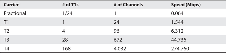
Table 4-11 A T-Carrier Hierarchy Summary Chart
As mentioned earlier, dedicated lines have their drawbacks. They are expensive and inflexible. If a company moves to another location, a T1 line cannot easily follow it. A dedicated line is expensive because companies have to pay for a dedicated connection with a lot of bandwidth even when they do not use the bandwidth. Not many companies require this level of bandwidth 24 hours a day. Instead, they may have data to send out here and there, but not continuously.
The cost of a dedicated line is determined by the distance to the destination. A T1 line run from one building to another building 2 miles away is much cheaper than a T1 line that covers 50 miles or a full state.
E-Carriers
E-carriers are similar to T-carrier telecommunication connections, where a single physical wire pair can be used to carry many simultaneous voice conversations by time-division multiplexing. Within this technology 30 channels interleave 8 bits of data in a frame. While the T-carrier and E-carrier technologies are similar, they are not interoperable. E-carriers are used by European countries.
The E-carrier channels and associated rates are shown in Table 4-12.
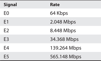
Table 4-12 E-carrier Characteristics
The most commonly used channels used are E1 and E3 and fractional E-carrier lines.
Optical Carrier
High-speed fiber-optic connections are measured in optical carrier (OC) transmission rates. The transmission rates are defined by rate of the bit stream of the digital signal and are designated by an integer value of the multiple of the basic unit of rate. They are generically referred to as OCx, where the “x” represents a multiplier of the basic OC-1 transmission rate, which is 51.84 Mbps. The carrier levels and speeds are shown in Table 4-13.
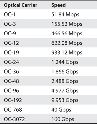
Table 4-13 OC Transmission Rates
Small and medium-sized companies that require high-speed Internet connectivity may use OC-3 or OC-12 connections. Service providers that require much larger amounts of bandwidth may use one or more OC-48 connections. OC-192 and greater connections are commonly used for the Internet backbone, which connects the largest networks in the world together.
Here are some other types of multiplexing functionalities you should be aware of:
Statistical time-division multiplexing (STDM):
• Transmits several types of data simultaneously across a single transmission cable or line (such as a T1 or T3 line).
• STDM analyzes statistics related to the typical workload of each input device (printer, fax, computer) and determines in real time how much time each device should be allocated for data transmission.
Frequency-division multiplexing (FDM):
• An available wireless spectrum is used to move data.
• Available frequency band is divided into narrow frequency bands and used to have multiple parallel channels for data transfer.
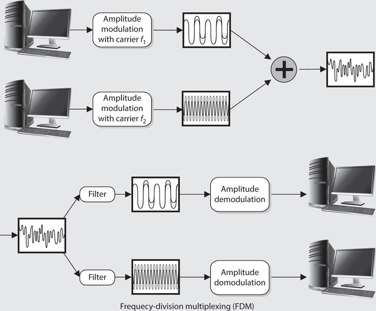
Wave-division multiplexing (WDM):
• Used in fiber-optic communication.
• Multiplexes a number of optical carrier signals onto a single optical fiber.
WAN Technologies
Several varieties of WAN technologies are available to companies today. The information that a company evaluates to decide which is the most appropriate WAN technology for it usually includes functionality, bandwidth demands, service level agreements, required equipment, cost, and what is available from service providers. The following sections go over some of the WAN technologies available today.
CSU/DSU
A channel service unit/data service unit (CSU/DSU) is required when digital equipment will be used to connect a LAN to a WAN. This connection can take place with T1 and T3 lines, as shown in Figure 4-63. A CSU/DSU is necessary because the signals and frames can vary between the LAN equipment and the WAN equipment used by service providers.
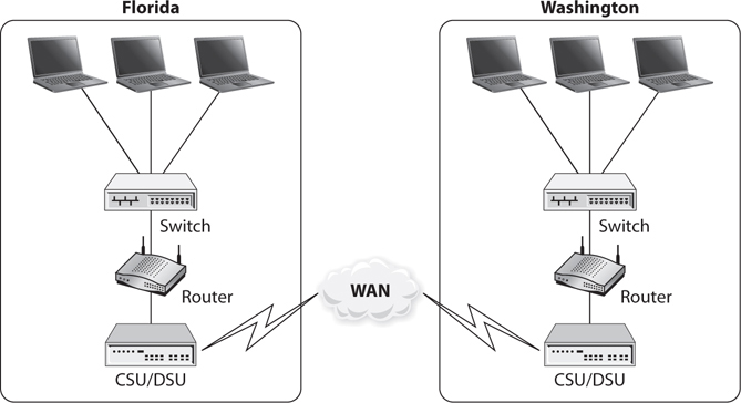
Figure 4-63 A CSU/DSU is required for digital equipment to communicate with telecommunications lines.
The DSU device converts digital signals from routers, switches, and multiplexers into signals that can be transmitted over the service provider’s digital lines. The DSU device ensures that the voltage levels are correct and that information is not lost during the conversion. The CSU connects the network directly to the service provider’s line. The CSU/DSU is not always a separate device and can be part of a networking device.
The CSU/DSU provides a digital interface for data terminal equipment (DTE), such as terminals, multiplexers, or routers, and an interface to the data circuit-terminating equipment (DCE) device, such as a carrier’s switch. The CSU/DSU basically works as a translator and, at times, as a line conditioner.
Switching
Dedicated links have one single path to traverse; thus, there is no complexity when it comes to determining how to get packets to different destinations. Only two points of reference are needed when a packet leaves one network and heads toward the other. It gets much more complicated when thousands of networks are connected to each other, which is often when switching comes into play.
Two main types of switching can be used: circuit switching and packet switching. Circuit switching sets up a virtual connection that acts like a dedicated link between two systems. ISDN and telephone calls are examples of circuit switching, which is shown in the lower half of Figure 4-64.
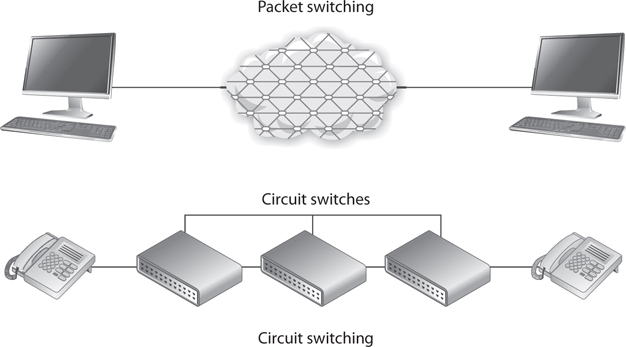
Figure 4-64 Circuit switching provides one road for a communication path, whereas packet switching provides many different possible roads.
When the source system makes a connection with the destination system, they set up a communication channel. If the two systems are local to each other, fewer devices need to be involved with setting up this channel. The farther the two systems are from each other, the more the devices are required to be involved with setting up the channel and connecting the two systems.
An example of how a circuit-switching system works is daily telephone use. When one person calls another, the same type of dedicated virtual communication link is set up. Once the connection is made, the devices supporting that communication channel do not dynamically move the call through different devices, which is what takes place in a packet-switching environment. The channel remains configured at the original devices until the call (connection) is done and torn down.
Packet switching, on the other hand, does not set up a dedicated virtual link, and packets from one connection can pass through a number of different individual devices (see the top of Figure 4-64), instead of all of them following one another through the same devices. Some examples of packet-switching technologies are the Internet, X.25, and frame relay. The infrastructure that supports these methods is made up of routers and switches of different types. They provide multiple paths to the same destinations, which offers a high degree of redundancy.
In a packet-switching network, the data is broken up into packets containing frame check sequence (FCS) numbers. These packets go through different devices, and their paths can be dynamically altered by a router or switch that determines a better route for a specific packet to take. Once the packets are received at the destination computer, all the packets are reassembled according to their FCS numbers and processed.
Because the path a packet will take in a packet-switching environment is not set in stone, there could be variable delays when compared to a circuit-switching technology. This is okay, because packet-switching networks usually carry data rather than voice. Because voice connections clearly detect these types of delays, in many situations a circuit-switching network is more appropriate for voice connections. Voice calls usually provide a steady stream of information, whereas a data connection is “burstier” in nature. When you talk on the phone, the conversation keeps a certain rhythm. You and your friend do not talk extremely fast and then take a few minutes in between conversations to stop talking and create a void with complete silence. However, this is usually how a data connection works. A lot of data is sent from one end to the other at one time, and then dead time occurs until it is time to send more data.
NOTE Voice over IP (VoIP) does move voice data over packet-switched environments. This technology is covered in the section “Multiservice Access Technologies,” later in the chapter.
Frame Relay
For a long time, many companies used dedicated links to communicate with other companies. Company A had a pipeline to company B that provided a certain bandwidth 24 hours a day and was not used by any other entities. This was great because only the two companies could use the line, so a certain level of bandwidth was always available, but it was expensive and most companies did not use the full bandwidth each and every hour the link was available. Thus, the companies spent a lot of money for a service they did not use all the time. Later, to avoid this unnecessary cost, companies turned to using frame relay instead of dedicated lines.
EXAM TIP Frame relay is an obsolescent technology. It is still in limited use, however, and you should be familiar with it for the CISSP exam.
Frame relay is a WAN technology that operates at the data link layer. It is a WAN solution that uses packet-switching technology to let multiple companies and networks share the same WAN medium, devices, and bandwidth. Whereas direct point-to-point links have a cost based on the distance between the endpoints, the frame relay cost is based on the amount of bandwidth used. Because several companies and networks use the same medium and devices (routers and switches), the cost can be greatly reduced per company compared to dedicated links.
If a company knows it will usually require a certain amount of bandwidth each day, it can pay a certain fee to make sure this amount of bandwidth is always available to it. If another company knows it will not have a high bandwidth requirement, it can pay a lower fee that does not guarantee the higher bandwidth allocation. This second company will have the higher bandwidth available to it anyway—at least until that link gets busy, and then the bandwidth level will decrease. (Companies that pay more to ensure that a higher level of bandwidth will always be available pay a committed information rate, or CIR.)
Two main types of equipment are used in frame relay connections: DTE and DCE, both of which were previously introduced in the discussion of CSU/DSU. The DTE is usually a customer-owned device, such as a router or switch, that provides connectivity between the company’s own network and the frame relay network. DCE is the service provider’s device, or telecommunications company’s device, that does the actual data transmission and switching in the frame relay cloud. So the DTE is a company’s ramp onto the frame relay network, and the DCE devices actually do the work within the frame relay cloud.
The frame relay cloud is the collection of DCE devices that provides switching and data communications functionality. Several service providers offer this type of service, and some providers use other providers’ equipment—it can all get confusing because a packet can take so many different routes. This collection is called a cloud to differentiate it from other types of networks and because when a packet hits this cloud, users do not usually know the route their frames will take. The frames will be sent either through permanent or switched virtual circuits that are defined within the DCE or through carrier switches.
NOTE The term cloud is used in several technologies: Internet cloud, ATM cloud, frame relay cloud, cloud computing, etc. The cloud is like a black box—we know our data goes in and we know it comes out, but we do not normally care about all the complex things that are taking place internally.
Frame relay is an any-to-any service that is shared by many users. As stated earlier, this is beneficial because the costs are much lower than those of dedicated leased lines. Because frame relay is shared, if one subscriber is not using its bandwidth, it is available for others to use. On the other hand, when traffic levels increase, the available bandwidth decreases. This is why subscribers who want to ensure a certain bandwidth is always available to them pay a higher CIR.
Figure 4-65 shows five sites being connected via dedicated lines versus five sites connected through the frame relay cloud. The first solution requires many dedicated lines that are expensive and not flexible. The second solution is cheaper and provides companies much more flexibility.
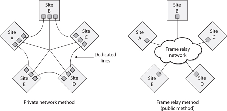
Figure 4-65 A private network connection requires several expensive dedicated links. Frame relay enables users to share a public network.
Virtual Circuits
Frame relay (and X.25) forwards frames across virtual circuits. These circuits can be either permanent, meaning they are programmed in advance, or switched, meaning the circuit is quickly built when it is needed and torn down when it is no longer needed. The permanent virtual circuit (PVC) works like a private line for a customer with an agreed-upon bandwidth availability. When a customer decides to pay for the CIR, a PVC is programmed for that customer to ensure it will always receive a certain amount of bandwidth.
Unlike PVCs, switched virtual circuits (SVCs) require steps similar to a dial-up and connection procedure. The difference is that a permanent path is set up for PVC frames, whereas when SVCs are used, a circuit must be built. It is similar to setting up a phone call over the public network. During the setup procedure, the required bandwidth is requested, the destination computer is contacted and must accept the call, a path is determined, and forwarding information is programmed into each switch along the SVC’s path. SVCs are used for teleconferencing, establishing temporary connections to remote sites, data replication, and voice calls. Once the connection is no longer needed, the circuit is torn down and the switches forget it ever existed.
Although a PVC provides a guaranteed level of bandwidth, it does not have the flexibility of an SVC. If a customer wants to use her PVC for a temporary connection, as mentioned earlier, she must call the carrier and have it set up, which can take hours.
X.25
X.25 is an older WAN protocol that defines how devices and networks establish and maintain connections. Like frame relay, X.25 is a switching technology that uses carrier switches to provide connectivity for many different networks. It also provides an any-to-any connection, meaning many users use the same service simultaneously. Subscribers are charged based on the amount of bandwidth they use, unlike dedicated links, for which a flat fee is charged.
Data is divided into 128 bytes and encapsulated in High-level Data Link Control (HDLC) frames. The frames are then addressed and forwarded across the carrier switches. Much of this sounds the same as frame relay—and it is—but frame relay is much more advanced and efficient when compared to X.25, because the X.25 protocol was developed and released in the 1970s. During this time, many of the devices connected to networks were dumb terminals and mainframes, the networks did not have built-in functionality and fault tolerance, and the Internet overall was not as foundationally stable and resistant to errors as it is today. When these characteristics were not part of the Internet, X.25 was required to compensate for these deficiencies and to provide many layers of error checking, error correcting, and fault tolerance. This made the protocol fat, which was required back then, but today it slows down data transmission and provides a lower performance rate than frame relay or ATM.
ATM
Asynchronous Transfer Mode (ATM) is another switching technology, but instead of being a packet-switching method, it uses a cell-switching method. ATM is a high-speed networking technology used for LAN, MAN, WAN, and service provider connections. Like frame relay, it is a connection-oriented switching technology, and creates and uses a fixed channel. IP is an example of a connectionless technology. Within the TCP/IP protocol suite, IP is connectionless and TCP is connection oriented. This means IP segments can be quickly and easily routed and switched without each router or switch in between having to worry about whether the data actually made it to its destination—that is TCP’s job. TCP works at the source and destination ends to ensure data was properly transmitted, and it resends data that ran into some type of problem and did not get delivered properly. When using ATM or frame relay, the devices in between the source and destination have to ensure that data gets to where it needs to go, unlike when a purely connectionless protocol is being used.
Since ATM is a cell-switching technology rather than a packet-switching technology, data is segmented into fixed-size cells of 53 bytes instead of variable-size packets. This provides for more efficient and faster use of the communication paths. ATM sets up virtual circuits, which act like dedicated paths between the source and destination. These virtual circuits can guarantee bandwidth and QoS. For these reasons, ATM is a good carrier for voice and video transmission.
ATM technology is used by carriers and service providers, and is the core technology of the Internet, but ATM technology can also be used for a company’s private use in backbones and connections to the service provider’s networks.
Traditionally, companies used dedicated lines, usually T-carrier lines, to connect to the public networks. However, companies have also moved to implementing an ATM switch on their network, which connects them to the carrier infrastructure. Because the fee is based on bandwidth used instead of a continual connection, it can be much cheaper. Some companies have replaced their Fast Ethernet and FDDI backbones with ATM. When a company uses ATM as a private backbone, the company has ATM switches that take the Ethernet, or whatever data link technology is being used, and frame them into the 53-byte ATM cells.
Quality of Service Quality of Service (QoS) is a capability that allows a protocol to distinguish between different classes of messages and assign priority levels. Some applications, such as video conferencing, are time sensitive, meaning delays would cause unacceptable performance of the application. A technology that provides QoS allows an administrator to assign a priority level to time-sensitive traffic. The protocol then ensures this type of traffic has a specific or minimum rate of delivery.
QoS allows a service provider to guarantee a level of service to its customers. QoS began with ATM and then was integrated into other technologies and protocols responsible for moving data from one place to another. Four different types of ATM QoS services (listed next) are available to customers. Each service maps to a specific type of data that will be transmitted.
• Constant bit rate (CBR) A connection-oriented channel that provides a consistent data throughput for time-sensitive applications, such as voice and video applications. Customers specify the necessary bandwidth requirement at connection setup.
• Variable bit rate (VBR) A connection-oriented channel best used for delay-insensitive applications because the data throughput flow is uneven. Customers specify their required peak and sustained rate of data throughput.
• Unspecified bit rate (UBR) A connectionless channel that does not promise a specific data throughput rate. Customers cannot, and do not need to, control their traffic rate.
• Available bit rate (ABR) A connection-oriented channel that allows the bit rate to be adjusted. Customers are given the bandwidth that remains after a guaranteed service rate has been met.
ATM was the first protocol to provide true QoS, but as the computing society has increased its desire to send time-sensitive data throughout many types of networks, developers have integrated QoS into other technologies.
QoS has three basic levels:
• Best-effort service No guarantee of throughput, delay, or delivery. Traffic that has priority classifications goes before traffic that has been assigned this classification. Most of the traffic that travels on the Internet has this classification.
• Differentiated service Compared to best-effort service, traffic that is assigned this classification has more bandwidth, shorter delays, and fewer dropped frames.
• Guaranteed service Ensures specific data throughput at a guaranteed speed. Time-sensitive traffic (voice and video) is assigned this classification.
Administrators can set the classification priorities (or use a policy manager product) for the different traffic types, which the protocols and devices then carry out.
Controlling network traffic to allow for the optimization or the guarantee of certain performance levels is referred to as traffic shaping. Using technologies that have QoS capabilities allows for traffic shaping, which can improve latency and increase bandwidth for specific traffic types, bandwidth throttling, and rate limiting.
SDLC
Synchronous Data Link Control (SDLC) is a protocol used in networks that use dedicated, leased lines with permanent physical connections. It is used mainly for communications with IBM hosts within a Systems Network Architecture (SNA). Developed by IBM in the 1970s, SDLC is a bit-oriented, synchronous protocol that has evolved into other communication protocols, such as HDLC, Link Access Procedure (LAP), and Link Access Procedure-Balanced (LAPB).
SDLC was developed to enable mainframes to communicate with remote locations. The environments that use SDLC usually have primary systems that control secondary stations’ communication. SDLC provides the polling media access technology, which is the mechanism that enables secondary stations to communicate on the network. Figure 4-66 shows the primary and secondary stations on an SDLC network.
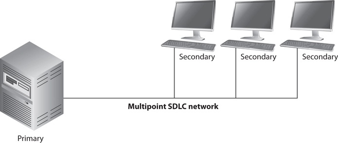
Figure 4-66 SDLC is used mainly in mainframe environments within an SNA network.
HDLC
High-level Data Link Control (HDLC) is a protocol that is also a bit-oriented link layer protocol and is used for serial device-to-device WAN communication. HDLC is an extension of SDLC, which was mainly used in SNA environments. SDLC basically died out as the mainframe environments using SNA reduced greatly in numbers. HDLC stayed around and evolved.
So what does a bit-oriented link layer protocol really mean? If you think back to the OSI model, you remember that at the data link layer packets have to be framed. This means the last header and trailer are added to the packet before it goes onto the wire and is sent over the network. There is a lot of important information that actually has to go into the header. There are flags that indicate if the connection is half or full duplex, switched or not switched, point-to-point or multipoint paths, compression data, authentication data, etc. If you send some frames to Etta and she does not know how to interpret these flags in the frame headers, that means you and Etta are not using the same data link protocol and cannot communicate. If your system puts a PPP header on a frame and sends it to Etta’s system, which is only configured with HDLC, her system does not know how to interpret the first header, and thus cannot process the rest of the data. As an analogy, let’s say the first step between you and Etta communicating requires that you give her a piece of paper that outlines how she is supposed to talk to you. These are the rules she has to know and follow to be able to communicate with you. You hand this piece of paper to Etta and the necessary information is there, but it is written in Italian. Etta does not know Italian, and thus does not know how to move forward with these communication efforts. She will just stand there and wait for someone else to come and give her a piece of paper with information on it that she can understand and process.
NOTE HDLC is a framing protocol that is used mainly for device-to-device communication, such as two routers communicating over a WAN link.
Point-to-Point Protocol
Point-to-Point Protocol (PPP) is similar to HDLC in that it is a data link protocol that carries out framing and encapsulation for point-to-point connections. A point-to-point connection means there is one connection between one device (point) and another device (point). If the systems on your LAN use the Ethernet protocol, what happens when a system needs to communicate to a server at your ISP for Internet connectivity? This is not an Ethernet connection, so how do the systems know how to communicate with each other if they cannot use Ethernet as their data link protocol? They use a data link protocol they do understand. Telecommunication devices commonly use PPP as their data link protocol.
PPP carries out several functions, including the encapsulation of multiprotocol packets; it has a Link Control Protocol (LCP) that establishes, configures, and maintains the connection; Network Control Protocols (NCPs) are used for network layer protocol configuration; and it provides user authentication capabilities through Password Authentication Protocol (PAP), Challenge Handshake Authentication Protocol (CHAP), and Extensible Authentication Protocol (EAP).
CAUTION PAP sends passwords in cleartext and is insecure. If you must use PAP, then ensure you do so on an encrypted connection only.
LCP is used to carry out the encapsulation format options, handle varying limits on sizes of packets, detect a looped-back link and other common misconfiguration errors, and terminate the link when necessary. LCP is the generic maintenance component used for each and every connection. So LCP makes sure the foundational functions of an actual connection work properly, and NCP makes sure that PPP can integrate and work with many different protocols. If PPP just moved IP traffic from one place to the other, it would not need NCPs. PPP has to “plug in” and work with different network layer protocols, and various network layer protocol configurations have to change as a packet moves from one network to another one. So PPP uses NCPs to be able to understand and work with different network layer protocols (IP, IPX, NetBEUI, AppleTalk).
If you are new to networking, all of these protocols can get quite confusing. For example, this chapter has already covered the following data link protocols: Ethernet, Token Ring, FDDI, ATM, frame relay, SDLC, HDLC, and now PPP and we have not even gotten to PPTP, Wi-Fi, or WiMAX. Why in the world do we need so many data link protocols?
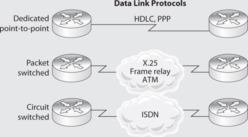
Data link protocols control how devices talk to each other, and networks have a lot of different devices that need to communicate. Some devices work within LAN environments (Ethernet, Token Ring, Wi-Fi), some in MAN environments (FDDI, WiMAX, Metro Ethernet), and some in WAN environments (frame relay, ATM). Some devices communicate directly to each other over point-to-point connections (HDLC, PPP). A computer that has an Ethernet NIC does not know how to talk to a computer that has a Token Ring NIC. A computer that has a Wi-Fi NIC does not know how to talk to a switch that has an ATM NIC. While it might seem like it would be less confusing if all devices just used one data link protocol, it is not possible because each device and each protocol has its own functions and responsibilities.
As an analogy, think about how different professions have their own language and terminology. Medical personnel use terms such as “dacryoadenitis,” “macrovascular,” and “sacrum.” Accounting personnel use words such as “ledger,” “trade receivables,” and “capital.” Techies use terms such as “C++,” “cluster,” and “parity.” Each profession has its own responsibilities, and because each is specialized and complex, it has its own language. You do not want a techie working on your sacrum, a doctor fixing your cluster, or either of them maintaining your ledgers. If your doctor asks you what is wrong and you start telling him that your web server has experienced a buffer overflow, your browser experienced a man-in-the-middle attack, or that your LAN experienced an ARP spoof attack, he can’t help you because he can’t understand you. Our networking devices also have their own responsibilities and their own languages (data link protocols).
HSSI
High-Speed Serial Interface (HSSI) is an interface used to connect multiplexers and routers to high-speed communications services such as ATM and frame relay. It supports speeds up to 52 Mbps, as in T3 WAN connections, which are usually integrated with router and multiplex devices to provide serial interfaces to the WAN. These interfaces define the electrical and physical interfaces to be used by DTE/DCE devices; thus, HSSI works at the physical layer.
Multiservice Access Technologies
Multiservice access technologies combine several types of communication categories (data, voice, and video) over one transmission line. This provides higher performance, reduced operational costs, and greater flexibility, integration, and control for administrators. The regular phone system is based on a circuit-switched, voice-centric network, called the public-switched telephone network (PSTN). The PSTN uses circuit switching instead of packet switching. When a phone call is made, the call is placed at the PSTN interface, which is the user’s telephone. This telephone is connected to the telephone company’s local loop via copper wiring. Once the signals for this phone call reach the telephone company’s central office (the end of the local loop), they are part of the telephone company’s circuit-switching world. A connection is made between the source and the destination, and as long as the call is in session, the data flows through the same switches.
When a phone call is made, the connection has to be set up, signaling has to be controlled, and the session has to be torn down. This takes place through the Signaling System 7 (SS7) protocol. When Voice over IP (VoIP) is used, it employs the Session Initiation Protocol (SIP), which sets up and breaks down the call sessions, just as SS7 does for non-IP phone calls. SIP is an application layer protocol that can work over TCP or UDP. SIP provides the foundation to allow the more complex phone-line features that SS7 provides, such as causing a phone to ring, dialing a phone number, generating busy signals, and so on.
The PSTN is being replaced by data-centric, packet-oriented networks that can support voice, data, and video. The new VoIP networks use different switches, protocols, and communication links compared to PSTN. This means VoIP has to go through a tricky transition stage that enables the old systems and infrastructures to communicate with the new systems until the old systems are dead and gone.
High-quality compression is used with VoIP technology, and the identification numbers (phone numbers) are IP addresses. This technology gets around some of the barriers present in the PSTN today. The PSTN interface devices (telephones) have limited embedded functions and logic, and the PSTN environment as a whole is inflexible in that new services cannot be easily added. In VoIP, the interface to the network can be a computer, server, PBX, or anything else that runs a telephone application. This provides more flexibility when it comes to adding new services and provides a lot more control and intelligence to the interfacing devices. The traditional PSTN has basically dumb interfaces (telephones without much functionality), and the telecommunication infrastructure has to provide all the functionality. In VoIP, the interfaces are the “smart ones” and the network just moves data from one point to the next.
Because VoIP is a packet-oriented switching technology, latency delays are possible. This manifests as longer delays within a conversation and a slight loss of synchronicity in the conversation. When someone using VoIP for a phone call experiences these types of lags in the conversation, it means the packets holding the other person’s voice message got queued somewhere within the network and are on their way. This is referred to as jitter, but protocols are developed to help smooth out these issues and provide a more continuous telephone call experience.
TIP Applications that are time sensitive, such as voice and video signals, need to work over an isochronous network. An isochronous network contains the necessary protocols and devices that guarantee continuous bandwidth without interruption.
Four main components are needed for VoIP: an IP telephony device, a call-processing manager, a voicemail system, and a voice gateway. The IP telephony device is just a phone that has the necessary software that allows it to work as a network device. Traditional phone systems require a “smart network” and a “dumb phone.” In VoIP, the phone must be “smart” by having the necessary software to take analog signals, digitize them, break them into packets, and create the necessary headers and trailers for the packets to find their destination. The voicemail system is a storage place for messages and provides user directory lookups and call-forwarding functionality. A voice gateway carries out packet routing and provides access to legacy voice systems and backup calling processes.
When a user makes a call, his “smart phone” will send a message to the call-processing manager to indicate a call needs to be set up. When the person at the destination takes her phone off the hook, this notifies the call-processing manager that the call has been accepted. The call-processing manager notifies both the sending and receiving phones that the channel is active, and voice data is sent back and forth over a traditional data network line.
Moving voice data through packets is more involved than moving regular data through packets. This is because data is usually sent in bursts, in which voice data is sent as a constant stream. A delay in data transmission is not noticed as much as is a delay in voice transmission. The VoIP technology, and its supporting protocols, has advanced to provide voice data transmission with increased bandwidth, while reducing variability in delay, round-trip delay, and packet loss issues.
Using VoIP means a company has to pay for and maintain only one network, instead of one network dedicated to data transmission and another network dedicated to voice transmission. This saves money and administration overhead, but certain security issues must be understood and dealt with.
NOTE A media gateway is the translation unit between disparate telecommunications networks. VoIP media gateways perform the conversion between TDM voice to VoIP, for example.
H.323 Gateways
The ITU-T recommendations cover a wide variety of multimedia communication services. H.323 is part of this family of recommendations, but it is also a standard that deals with video, real-time audio, and data packet–based transmissions where multiple users can be involved with the data exchange. An H.323 environment features terminals, which can be telephones or computers with telephony software, gateways that connect this environment to the PSTN, multipoint control units, and gatekeepers that manage calls and functionality.
Like any type of gateway, H.323 gateways connect different types of systems and devices and provide the necessary translation functionality. The H.323 terminals are connected to these gateways, which in turn can be connected to the PSTN. These gateways translate protocols used on the circuit-based telephone network and the packet-based VoIP network. The gateways also translate the circuit-oriented traffic into packet-oriented traffic and vice versa as required.
Today, it is necessary to implement the gateways that enable the new technology to communicate with the old, but soon the old PSTN may be a thing of the past and all communication may take place over packets instead of circuits.
The newer technology looks to provide transmission mechanisms that will involve much more than just voice. Although we have focused mainly on VoIP, other technologies support the combination of voice and data over the same network, such as Voice over ATM (VoATM) and Voice over Frame Relay (VoFR). ATM and frame relay are connection-oriented protocols, and IP is connectionless. This means frame relay and ATM commonly provide better QoS and less jitter and latency.
The best of both worlds is to combine IP over ATM or frame relay. This allows for packet-oriented communication over a connection-oriented network that will provide an end-to-end connection. IP is at the network layer and is medium independent—it can run over a variety of data link layer protocols and technologies.
Traditionally, a company has on its premises a PBX, which is a switch between the company and the PSTN, and T1 or T3 lines connecting the PBX to the telephone company’s central office, which houses switches that act as ramps onto the PSTN. When WAN technologies are used instead of accessing the PSTN through the central office switches, the data is transmitted over the frame relay, ATM, or Internet clouds. An example of this configuration is shown in Figure 4-67.
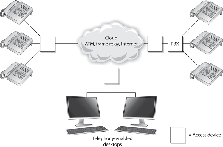
Figure 4-67 Regular telephone calls connect phones to the PSTN. Voice over WAN technologies connect calls to a WAN.
Because frame relay and ATM utilize PVCs and SVCs, they both have the ability to use SVCs for telephone calls. Remember that a CIR is used when a company wants to ensure it will always have a certain bandwidth available. When a company pays for this guaranteed bandwidth, it is paying for a PVC for which the switches and routers are programmed to control its connection and for that connection to be maintained. SVCs, on the other hand, are set up on demand and are temporary in nature. They are perfect for making telephone calls or transmitting video during videoconferencing.
Digging Deeper into SIP
As stated earlier, SIP is a signaling protocol widely used for VoIP communications sessions. It is used in applications such as video conferencing, multimedia, instant messaging, and online gaming. It is analogous to the SS7 protocol used in PSTN networks and supports features present in traditional telephony systems.
SIP consists of two major components: the User Agent Client (UAC) and User Agent Server (UAS). The UAC is the application that creates the SIP requests for initiating a communication session. UACs are generally messaging tools and soft-phone applications that are used to place VoIP calls. The UAS is the SIP server, which is responsible for handling all routing and signaling involved in VoIP calls.
SIP relies on a three-way-handshake process to initiate a session. To illustrate how an SIP-based call kicks off, let’s look at an example of two people, Bill and John, trying to communicate using their VoIP phones. Bill’s system starts by sending an INVITE packet to John’s system. Since Bill’s system is unaware of John’s location, the INVITE packet is sent to the SIP server, which looks up John’s address in the SIP registrar server. Once the location of John’s system has been determined, the INVITE packet is forwarded to him. During this entire process, the server keeps the caller (Bill) updated by sending him a TRYING packet, indicating the process is underway. Once the INVITE packet reaches John’s system, it starts ringing. While John’s system rings and waits for John to respond, it sends a RINGING packet to Bill’s system, notifying Bill that the INVITE packet has been received and John’s system is waiting for John to accept the call. As soon as John answers the call, an OK packet is sent to Bill’s system (through the server). Bill’s system now issues an ACK packet to begin call setup. It is important to note here that SIP itself is not used to stream the conversation because it’s just a signaling protocol. The actual voice stream is carried on media protocols such as the Real-time Transport Protocol (RTP). RTP provides a standardized packet format for delivering audio and video over IP networks. Once Bill and John are done communicating, a BYE message is sent from the system terminating the call. The other system responds with an OK, acknowledging the session has ended. This handshake is illustrated in Figure 4-68.
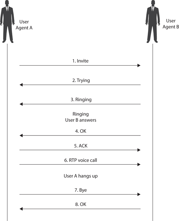
Figure 4-68 SIP handshake
The SIP architecture consists of three different types of servers, which play an integral role in the entire communication process of the VoIP system. These servers are the proxy server, the registrar server, and the redirect server. The proxy server is used to relay packets within a network between the UACs and the UAS. It also forwards requests generated by callers to their respective recipients. Proxy servers are also generally used for name mapping, which allows the proxy server to interlink an external SIP system to an internal SIP client.
The registrar server keeps a centralized record of the updated locations of all the users on the network. These addresses are stored on a location server. The redirect server allows SIP devices to retain their SIP identities despite changes in their geographic location. This allows a device to remain accessible when its location is physically changed and hence while it moves through different networks. The use of redirect servers allows clients to remain within reach while they move through numerous network coverage zones. This configuration is generally known as an intraorganizational configuration. Intraorganizational routing enables SIP traffic to be routed within a VoIP network without being transmitted over the PSTN or external network.
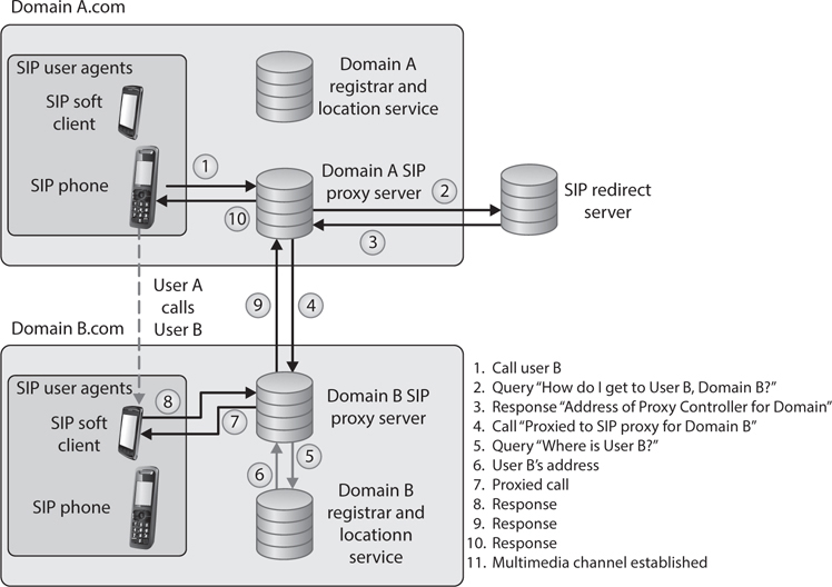
Skype is a popular Internet telephony application that uses a peer-to-peer communication model rather than the traditional client/server approach of VoIP systems. The Skype network does not rely on centralized servers to maintain its user directories. Instead, user records are maintained across distributed member nodes. This is the reason the network can quickly accommodate user surges without having to rely on expensive central infrastructure and computing resources.