
CHAPTER 4
Communication and Network Security
This chapter presents the following:
• OSI and TCP/IP models
• Protocol types and security issues
• LAN, WAN, MAN, intranet, and extranet technologies
• Cable types and data transmission types
• Network devices and services
• Communications security management
• Telecommunications devices and technologies
• Remote connectivity technologies
• Wireless technologies
• Network encryption
• Threats and attacks
• Software-defined routing
• Content distribution networks
• Multilayer protocols
• Convergent network technologies
The Internet… it’s a series of tubes.
—Ted Stevens
Telecommunications and networking use various mechanisms, devices, software, and protocols that are interrelated and integrated. Networking is one of the more complex topics in the computer field, mainly because so many technologies are involved and are evolving. Our current technologies are constantly evolving, and every month there seems to be new “emerging” technologies that we have to learn, understand, implement, and secure. A network administrator must know how to configure networking software, protocols and services, and devices; deal with interoperability issues; install, configure, and interface with telecommunications software and devices; and troubleshoot effectively. A security professional must understand these issues and be able to analyze them a few levels deeper to recognize fully where vulnerabilities can arise within each of these components and then know what to do about them. This can be a challenging task. However, if you are knowledgeable, have a solid practical skill set, and are willing to continue to learn, you can have more career opportunities than you know what to do with.
While almost every country in the world has had to deal with hard economic times, one industry that has not been greatly affected by the downward economies is information security. Organizations and government agencies do not have a large enough pool of people with the necessary skill set to hire from, and the attacks against these entities are only increasing and becoming more critical. Security is a good business to be in, if you are truly knowledgeable, skilled, and disciplined.
Ten years ago, it seemed possible to understand a network and everything that resided within it. As technology grew in importance in every aspect of our lives over the years, however, almost every component that made up a traditional network grew in complexity. We still need to know the basics (routers, firewalls, TCP/IP protocols, cabling, switching technologies, etc.), but now we also need to understand data loss prevention, web and e-mail security, mobile technologies, antimalware products, virtualization, cloud computing, endpoint security solutions, radio-frequency identification (RFID), virtual private network protocols, social networking threats, wireless technologies, continuous monitoring capabilities, and more. Our society has come up with so many different real-time communication technologies (instant messaging, IP telephony, video conferencing, SMS, etc.), we had to develop unified communication models to allow for interoperability and optimization. The IEEE (Institute of Electrical and Electronics Engineers) standards that define various editions and components of wireless local area network (WLAN) technologies have gone through the whole alphabet (802.11a, 802.11b, 802.11c, 802.11d, 802.11e, 802.11f, etc.) and we have had to start doubling up on our letters, as in IEEE 802.11ac. Mobile communication technology has gone from 1G to 4G, with some half G’s in between (2.5G, 3.5G). And as the technology increases in complexity and the attackers become more determined and creative, we need to understand not only basic attack types (buffer overflows, fragmentation attacks, DoS, viruses, social engineering), but also the more advanced attack types (client-side, injection, fuzzing, pointer manipulation, cache poisoning, etc.).
A network used to be a construct with boundaries, but today most environments do not have clear-cut boundaries. Most communication gadgets are some type of computer (smartphones, tablets, medical devices and appliances, etc.) and these devices do not stay within the walls of an office as people hit the road, telecommute, and work from virtual offices. The increased use of outsourcing also increases the boundaries of our traditional networks and with so many entities needing access, the boundaries are commonly porous in nature.
As our technologies continue to explode with complexity, the threats of compromise from attackers continue to increase—not just in volume but in criticality. Today’s attackers are commonly part of organized crime rings or funded by nation-states (and sometimes both). This means that the attackers are trained, organized, and very focused. Various ways of stealing funds (siphoning, identity theft, money mules, carding) are rampant; stealing intellectual property is continuously on the rise, and cyber warfare is becoming more well known. When the Stuxnet worm negatively affected Iran’s uranium enrichment infrastructure in 2010 and was widely reported in the news, the world became more aware of what malware is capable of.
Today’s security professional needs to understand many things on many different levels because the world of technology is only getting more complex and the risks are only increasing. In this chapter we will start with the basics of networking and telecommunications and build upon them and identify many of the security issues that are involved.
Telecommunications
Telecommunications is the electromagnetic transmission of data among systems, whether through analog, digital, or wireless transmission types. The data can flow through copper wires; coaxial cable; airwaves; the telephone company’s public-switched telephone network (PSTN); and a service provider’s fiber cables, switches, and routers. Definitive lines exist between the media used for transmission, the technologies, the protocols, and whose equipment is being used. However, the definitive lines get blurry when one follows how data created on a user’s workstation flows within seconds through a complex path of Ethernet cables, to a router that divides the company’s network and the rest of the world, through the Asynchronous Transfer Mode (ATM) switch provided by the service provider, to the many switches the packets traverse throughout the ATM cloud, on to another company’s network, through its router, and to another user’s workstation. Each piece is interesting, but when they are all integrated and work together, it is awesome.
Telecommunications usually refers to telephone systems, service providers, and carrier services. Most telecommunications systems are regulated by governments and international organizations. In the United States, the Federal Communications Commission (FCC) regulates telecommunications systems, which includes voice and data transmissions. In Canada, Industry Canada regulates telecommunications systems through the Spectrum, Information Technologies and Telecommunications (SITT) service standard. Globally, organizations develop policies, recommend standards, and work together to provide standardization and the capability for different technologies to properly interact.
The main standards organizations are the International Telecommunication Union (ITU) and the International Standards Organization (ISO). Their models and standards have shaped our technology today, and the technological issues governed by these organizations are addressed throughout this chapter.
Open Systems Interconnection Reference Model
ISO is a worldwide federation that works to provide international standards. In the early 1980s, ISO worked to develop a protocol set that would be used by all vendors throughout the world to allow the interconnection of network devices. This movement was fueled with the hopes of ensuring that all vendor products and technologies could communicate and interact across international and technical boundaries. The actual protocol set did not catch on as a standard, but the model of this protocol set, the Open Systems Interconnection (OSI) reference model, was adopted and is used as an abstract framework to which most operating systems and protocols adhere.
Many people think that the OSI reference model arrived at the beginning of the computing age as we know it and helped shape and provide direction for many, if not all, networking technologies. However, this is not true. In fact, it was introduced in 1984, at which time the basics of the Internet had already been developed and implemented, and the basic Internet protocols had been in use for many years. The Transmission Control Protocol/Internet Protocol (TCP/IP) suite actually has its own model that is often used today when examining and understanding networking issues. Figure 4-1 shows the differences between the OSI and TCP/IP networking models. In this chapter, we will focus more on the OSI model.

Figure 4-1 The OSI and TCP/IP networking models

NOTE The host-to-host layer is sometimes called the transport layer in the TCP/IP model. The application layer in the TCP/IP architecture model is equivalent to a combination of the application, presentation, and session layers in the OSI model.
Protocol
A network protocol is a standard set of rules that determines how systems will communicate across networks. Two different systems that use the same protocol can communicate and understand each other despite their differences, similar to how two people can communicate and understand each other by using the same language.
The OSI reference model, as described by ISO Standard 7498-1, provides important guidelines used by vendors, engineers, developers, and others. The model segments the networking tasks, protocols, and services into different layers. Each layer has its own responsibilities regarding how two computers communicate over a network. Each layer has certain functionalities, and the services and protocols that work within that layer fulfill them.
The OSI model’s goal is to help others develop products that will work within an open network architecture. An open network architecture is one that no vendor owns, that is not proprietary, and that can easily integrate various technologies and vendor implementations of those technologies. Vendors have used the OSI model as a jumping-off point for developing their own networking frameworks. These vendors use the OSI model as a blueprint and develop their own protocols and services to produce functionality that is different from, or overlaps, that of other vendors. However, because these vendors use the OSI model as their starting place, integration of other vendor products is an easier task, and the interoperability issues are less burdensome than if the vendors had developed their own networking framework from scratch.
Although computers communicate in a physical sense (electronic signals are passed from one computer over a wire to the other computer), they also communicate through logical channels. Each protocol at a specific OSI layer on one computer communicates with a corresponding protocol operating at the same OSI layer on another computer. This happens through encapsulation.

Here’s how encapsulation works: A message is constructed within a program on one computer and is then passed down through the network protocol’s stack. A protocol at each layer adds its own information to the message; thus, the message grows in size as it goes down the protocol stack. The message is then sent to the destination computer, and the encapsulation is reversed by taking the packet apart through the same steps used by the source computer that encapsulated it. At the data link layer, only the information pertaining to the data link layer is extracted, and the message is sent up to the next layer. Then at the network layer, only the network layer data is stripped and processed, and the packet is again passed up to the next layer, and so on. This is how computers communicate logically. The information stripped off at the destination computer informs it how to interpret and process the packet properly. Data encapsulation is shown in Figure 4-2.

Figure 4-2 Each OSI layer protocol adds its own information to the data packet.
A protocol at each layer has specific responsibilities and control functions it performs, as well as data format syntaxes it expects. Each layer has a special interface (connection point) that allows it to interact with three other layers: (1) communications from the interface of the layer above it, (2) communications to the interface of the layer below it, and (3) communications with the same layer in the interface of the target packet address. The control functions, added by the protocols at each layer, are in the form of headers and trailers of the packet.
The benefit of modularizing these layers, and the functionality within each layer, is that various technologies, protocols, and services can interact with each other and provide the proper interfaces to enable communications. This means a computer can use an application protocol developed by Novell, a transport protocol developed by Apple, and a data link protocol developed by IBM to construct and send a message over a network. The protocols, technologies, and computers that operate within the OSI model are considered open systems. Open systems are capable of communicating with other open systems because they implement international standard protocols and interfaces. The specification for each layer’s interface is very structured, while the actual code that makes up the internal part of the software layer is not defined. This makes it easy for vendors to write plug-ins in a modularized manner. Systems are able to integrate the plug-ins into the network stack seamlessly, gaining the vendor-specific extensions and functions.
Understanding the functionalities that take place at each OSI layer and the corresponding protocols that work at those layers helps you understand the overall communication process between computers. Once you understand this process, a more detailed look at each protocol will show you the full range of options each protocol provides and the security weaknesses embedded into each of those options.
Application Layer
The application layer, layer 7, works closest to the user and provides file transmissions, message exchanges, terminal sessions, and much more. This layer does not include the actual applications, but rather the protocols that support the applications. When an application needs to send data over the network, it passes instructions and the data to the protocols that support it at the application layer. This layer processes and properly formats the data and passes it down to the next layer within the OSI model. This happens until the data the application layer constructed contains the essential information from each layer necessary to transmit the data over the network. The data is then put on the network cable and transmitted until it arrives at the destination computer.
As an analogy, let’s say that you write a letter that you would like to send to your congressman. Your job is to write the letter, your clerk’s job is to figure out how to get it to him, and the congressman’s job is to read your letter and respond to it. You (the application) create the content (message) and hand it to your assistant (application layer protocol). Your assistant puts the content into an envelope, writes the congressman’s address on the envelope (inserts headers and trailers), and puts it into the mailbox (passes it on to the next protocol in the network stack). When your assistant checks the mailbox a week later, there is a letter from the congressman (the remote application) addressed to you. Your assistant opens the envelope (strips off headers and trailers) and gives you the message (passes the message up to the application).
Some examples of the protocols working at this layer are the Simple Mail Transfer Protocol (SMTP), Hypertext Transfer Protocol (HTTP), Domain Name System (DNS), Internet Relay Chat (IRC) protocol, and the Line Printer Daemon (LDP) protocol. Figure 4-3 shows how applications communicate with the underlying protocols through application programming interfaces (APIs). If a user makes a request to send an e-mail message through her e-mail client Outlook, the e-mail client sends this information to SMTP. SMTP adds its information to the user’s message and passes it down to the presentation layer.

Figure 4-3 Applications send requests to an API, which is the interface to the supporting protocol.
Presentation Layer
The presentation layer, layer 6, receives information from the application layer protocol and puts it in a format that any process operating at the same layer on a destination computer following the OSI model can understand. This layer provides a common means of representing data in a structure that can be properly processed by the end system. This means that when a user creates a Word document and sends it out to several people, it does not matter whether the receiving computers have different word processing programs; each of these computers will be able to receive this file and understand and present it to its user as a document. It is the data representation processing that is done at the presentation layer that enables this to take place. For example, when a Windows 8 computer receives a file from another computer system, information within the file’s header indicates what type of file it is. The Windows 8 operating system has a list of file types it understands and a table describing what program should be used to open and manipulate each of these file types. For example, the sender could create a Portable Document Format (PDF) file in Word 2010, while the receiver uses a Linux system. The receiver can open this file because the presentation layer on the sender’s system encoded the file and added a descriptive header in accordance with the Multipurpose Internet Mail Extensions (MIME) standards, and the receiver’s computer interprets the header’s MIME type (Content-Type: application/pdf), decodes the file, and knows to open it with its PDF viewer application.
The presentation layer is not concerned with the meaning of data, but with the syntax and format of that data. It works as a translator, translating the format an application is using to a standard format used for passing messages over a network. If a user uses a Corel application to save a graphic, for example, the graphic could be a Tagged Image File Format (TIFF), Graphic Interchange Format (GIF), or Joint Photographic Experts Group (JPEG) format. The presentation layer adds information to tell the destination computer the file type and how to process and present it. This way, if the user sends this graphic to another user who does not have the Corel application, the user’s operating system can still present the graphic because it has been saved into a standard format. Figure 4-4 illustrates the conversion of a file into different standard file types.

Figure 4-4 The presentation layer receives data from the application layer and puts it into a standard format.
This layer also handles data compression and encryption issues. If a program requests a certain file to be compressed and encrypted before being transferred over the network, the presentation layer provides the necessary information for the destination computer. It provides information on how the file was encrypted and/or compressed so that the receiving system knows what software and processes are necessary to decrypt and decompress the file. Let’s say Sara compresses a file using WinZip and sends it to you. When your system receives this file, it looks at data within the header (Content-Type: application/zip) and knows what application can decompress the file. If your system has WinZip installed, then the file can be decompressed and presented to you in its original form. If your system does not have an application that understands the compression/decompression instructions, the file will be presented to you with an unassociated icon.
Session Layer
When two applications need to communicate or transfer data between themselves, a connection may need to be set up between them. The session layer, layer 5, is responsible for establishing a connection between the two applications, maintaining it during the transfer of data, and controlling the release of this connection. A good analogy for the functionality within this layer is a telephone conversation. When Kandy wants to call a friend, she uses the telephone. The telephone network circuitry and protocols set up the connection over the telephone lines and maintain that communication path, and when Kandy hangs up, they release all the resources they were using to keep that connection open.
Similar to how telephone circuitry works, the session layer works in three phases: connection establishment, data transfer, and connection release. It provides session restart and recovery if necessary and provides the overall maintenance of the session. When the conversation is over, this path is broken down and all parameters are set back to their original settings. This process is known as dialog management. Figure 4-5 depicts the three phases of a session. Some protocols that work at this layer are the Password Authentication Protocol (PAP), Point-to-Point Tunneling Protocol (PPTP), Network Basic Input Output System (NetBIOS), and Remote Procedure Call (RPC).

Figure 4-5 The session layer sets up the connection, maintains it, and tears it down once communication is completed.
The session layer protocol can enable communication between two applications to happen in three different modes:
• Simplex Communication takes place in one direction, though in practice this is very seldom the case.
• Half-duplex Communication takes place in both directions, but only one application can send information at a time.
• Full-duplex Communication takes place in both directions, and both applications can send information at the same time.
Many people have a hard time understanding the difference between what takes place at the session layer versus the transport layer because their definitions sound similar. Session layer protocols control application-to-application communication, whereas the transport layer protocols handle computer-to-computer communication. For example, if you are using a product that is working in a client/server model, in reality you have a small piece of the product on your computer (client portion) and the larger piece of the software product is running on a different computer (server portion). The communication between these two pieces of the same software product needs to be controlled, which is why session layer protocols even exist. Session layer protocols take on the functionality of middleware, which allows software on two different computers to communicate.
Session layer protocols provide interprocess communication channels, which allow a piece of software on one system to call upon a piece of software on another system without the programmer having to know the specifics of the software on the receiving system. The programmer of a piece of software can write a function call that calls upon a subroutine. The subroutine could be local to the system or be on a remote system. If the subroutine is on a remote system, the request is carried over a session layer protocol. The result that the remote system provides is then returned to the requesting system over the same session layer protocol. This is how RPC works. A piece of software can execute components that reside on another system. This is the core of distributed computing.

CAUTION One security issue common to RPC (and similar interprocess communication software) is the lack of authentication or the use of weak authentication. Secure RPC (SRPC) can be implemented, which requires authentication to take place before two computers located in different locations can communicate with each other. Authentication can take place using shared secrets, public keys, or Kerberos tickets. Session layer protocols need to provide secure authentication capabilities.
Session layer protocols are the least used protocols in a network environment; thus, many of them should be disabled on systems to decrease the chance of them getting exploited. RPC, NetBIOS, and similar distributed computing calls usually only need to take place within a network; thus, firewalls should be configured so this type of traffic is not allowed into or out of a network. Firewall filtering rules should be in place to stop this type of unnecessary and dangerous traffic.
Transport Layer
When two computers are going to communicate through a connection-oriented protocol, they will first agree on how much information each computer will send at a time, how to verify the integrity of the data once received, and how to determine whether a packet was lost along the way. The two computers agree on these parameters through a handshaking process at the transport layer, layer 4. The agreement on these issues before transferring data helps provide more reliable data transfer, error detection, correction, recovery, and flow control, and it optimizes the network services needed to perform these tasks. The transport layer provides end-to-end data transport services and establishes the logical connection between two communicating computers.
NOTE Connection-oriented protocols, such as Transmission Control Protocol (TCP), provide reliable data transmission when compared to connectionless protocols, such as User Datagram Protocol (UDP). This distinction is covered in more detail in the “TCP/IP Model” section, later in the chapter.
The functionality of the session and transport layers is similar insofar as they both set up some type of session or virtual connection for communication to take place. The difference is that protocols that work at the session layer set up connections between applications, whereas protocols that work at the transport layer set up connections between computer systems. For example, we can have three different applications on computer A communicating with three applications on computer B. The session layer protocols keep track of these different sessions. You can think of the transport layer protocol as the bus. It does not know or care what applications are communicating with each other. It just provides the mechanism to get the data from one system to another.
The transport layer receives data from many different applications and assembles the data into a stream to be properly transmitted over the network. The main protocols that work at this layer are TCP and UDP. Information is passed down from different entities at higher layers to the transport layer, which must assemble the information into a stream, as shown in Figure 4-6. The stream is made up of the various data segments passed to it. Just like a bus can carry a variety of people, the transport layer protocol can carry a variety of application data types.

Figure 4-6 TCP formats data from applications into a stream to be prepared for transmission.

TIP Different references can place specific protocols at different layers. For example, many references place the Transport Layer Security (TLS) protocol in the session layer, while other references place it in the transport layer. It is not that one is right or wrong. The OSI model tries to draw boxes around reality, but some protocols straddle the different layers.
Network Layer
The main responsibilities of the network layer, layer 3, are to insert information into the packet’s header so it can be properly addressed and routed, and then to actually route the packets to their proper destination. In a network, many routes can lead to one destination. The protocols at the network layer must determine the best path for the packet to take. Routing protocols build and maintain their routing tables. These tables are maps of the network, and when a packet must be sent from computer A to computer M, the protocols check the routing table, add the necessary information to the packet’s header, and send it on its way.
The protocols that work at this layer do not ensure the delivery of the packets. They depend on the protocols at the transport layer to catch any problems and resend packets if necessary. The Internet Protocol (IP) is a common protocol working at the network layer, although other routing and routed protocols work there as well. Some of the other protocols are the Internet Control Message Protocol (ICMP), Routing Information Protocol (RIP), Open Shortest Path First (OSPF), Border Gateway Protocol (BGP), and Internet Group Management Protocol (IGMP). Figure 4-7 shows that a packet can take many routes and that the network layer enters routing information into the header to help the packet arrive at its destination.
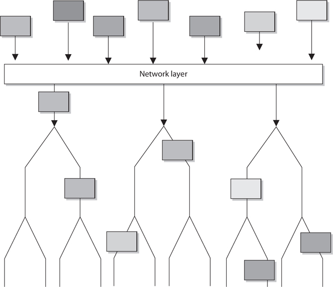
Figure 4-7 The network layer determines the most efficient path for each packet to take.
Data Link Layer
As we continue down the protocol stack, we are getting closer to the actual transmission channel (i.e., network wire) over which all the data will travel. The outer format of the data packet changes slightly at each layer, and it comes to a point where it needs to be translated into the LAN or wide area network (WAN) technology binary format for proper line transmission. This happens at the data link layer, layer 2.
LAN and WAN technologies can use different protocols, network interface cards (NICs), cables, and transmission methods. Each of these components has a different header data format structure, and they interpret electromagnetic signals in different ways. The data link layer is where the network stack knows in what format the data frame must be in order to transmit it properly over Token Ring, Ethernet, ATM, or Fiber Distributed Data Interface (FDDI) networks. If the network is an Ethernet network, for example, all the computers will expect packet headers to be a certain length, the flags to be positioned in certain field locations within the header, and the trailer information to be in a certain place with specific fields. Compared to Ethernet, Token Ring network technology has different frame header lengths, flag values, and header formats.
The data link layer is divided into two functional sublayers: the Logical Link Control (LLC) and the Media Access Control (MAC). The LLC, which was originally defined in the IEEE 802.2 specification for Ethernet networks and is now also the ISO/IEC 8802-2 standard, communicates with the protocol immediately above it, the network layer. The MAC will have the appropriately loaded protocols to interface with the protocol requirements of the physical layer.
As data is passed down the network stack, it has to go from the network layer to the data link layer. The protocol at the network layer does not know if the underlying network is Ethernet, Token Ring, or ATM—it does not need to have this type of insight. The protocol at the network layer just adds its header and trailer information to the packet and passes it on to the next layer, which is the LLC sublayer. The LLC sublayer takes care of flow control and error checking. Data coming from the network layer passes down through the LLC sublayer and goes to the MAC. The technology at the MAC sublayer knows if the network is Ethernet, Token Ring, or ATM, so it knows how to put the last header and trailer on the packet before it “hits the wire” for transmission.
The IEEE MAC specification for Ethernet is 802.3, Token Ring is 802.5, wireless LAN is 802.11, and so on. So when you see a reference to an IEEE standard, such as 802.11, 802.16, or 802.3, it refers to the protocol working at the MAC sublayer of the data link layer of a protocol stack.
Some of the protocols that work at the data link layer are the Point-to-Point Protocol (PPP), ATM, Layer 2 Tunneling Protocol (L2TP), FDDI, Ethernet, and Token Ring. Figure 4-8 shows the two sublayers that make up the data link layer.

Figure 4-8 The data link layer is made up of two sublayers.
Each network technology (Ethernet, ATM, FDDI, and so on) defines the compatible physical transmission type (coaxial, twisted pair, fiber, wireless) that is required to enable network communication. Each network technology also has defined electronic signaling and encoding patterns. For example, if the MAC sublayer received a bit with the value of 1 that needed to be transmitted over an Ethernet network, the MAC sublayer technology would tell the physical layer to create a +0.5-volt electric signal. In the “language of Ethernet” this means that 0.5 volts is the encoding value for a bit with the value of 1. If the next bit the MAC sublayer receives is 0, the MAC layer would tell the physical layer to transmit 0 volts. The different network types will have different encoding schemes. So a bit value of 1 in an ATM network might actually be encoded to the voltage value of 0.85. It is just a sophisticated Morse code system. The receiving end will know when it receives a voltage value of 0.85 that a bit with the value of 1 has been transmitted.
Network cards bridge the data link and physical layers. Data is passed down through the first six layers and reaches the network card driver at the data link layer. Depending on the network technology being used (Ethernet, Token Ring, FDDI, and so on), the network card driver encodes the bits at the data link layer, which are then turned into electricity states at the physical layer and placed onto the wire for transmission.

EXAM TIP When the data link layer applies the last header and trailer to the data message, this is referred to as framing. The unit of data is now called a frame.
Physical Layer
The physical layer, layer 1, converts bits into voltage for transmission. Signals and voltage schemes have different meanings for different LAN and WAN technologies, as covered earlier. If a user sends data through his dial-up software and out his modem onto a telephone line, the data format, electrical signals, and control functionality are much different than if that user sends data through the NIC and onto a unshielded twisted pair (UTP) wire for LAN communication. The mechanisms that control this data going onto the telephone line, or the UTP wire, work at the physical layer. This layer controls synchronization, data rates, line noise, and transmission techniques. Specifications for the physical layer include the timing of voltage changes, voltage levels, and the physical connectors for electrical, optical, and mechanical transmission.
EXAM TIP To remember all the layers within the OSI model in the correct order, memorize “All People Seem To Need Data Processing.” Remember that you are starting at layer 7, the application layer, at the top.
Functions and Protocols in the OSI Model
For the CISSP exam, you will need to know the functionality that takes place at the different layers of the OSI model, along with specific protocols that work at each layer. The following is a quick overview of each layer and its components.
Application
The protocols at the application layer handle file transfer, virtual terminals, network management, and fulfilling networking requests of applications. A few of the protocols that work at this layer include
• File Transfer Protocol (FTP)
• Trivial File Transfer Protocol (TFTP)
• Simple Network Management Protocol (SNMP)
• Simple Mail Transfer Protocol (SMTP)
• Telnet
• Hypertext Transfer Protocol (HTTP)
Presentation
The services of the presentation layer handle translation into standard formats, data compression and decompression, and data encryption and decryption. No protocols work at this layer, just services. The following lists some of the presentation layer standards:
• American Standard Code for Information Interchange (ASCII)
• Extended Binary-Coded Decimal Interchange Mode (EBCDIC)
• Tagged Image File Format (TIFF)
• Joint Photographic Experts Group (JPEG)
• Motion Picture Experts Group (MPEG)
• Musical Instrument Digital Interface (MIDI)
Session
The session layer protocols set up connections between applications; maintain dialog control; and negotiate, establish, maintain, and tear down the communication channel. Some of the protocols that work at this layer include
• Network Basic Input Output System (NetBIOS)
• Password Authentication Protocol (PAP)
• Point-to-Point Tunneling Protocol (PPTP)
• Remote Procedure Call (RPC)
Transport
The protocols at the transport layer handle end-to-end transmission and segmentation of a data stream. The following protocols work at this layer:
• Transmission Control Protocol (TCP)
• User Datagram Protocol (UDP)
• Sequenced Packet Exchange (SPX)
Network
The responsibilities of the network layer protocols include internetworking service, addressing, and routing. The following lists some of the protocols that work at this layer:
• Internet Protocol (IP)
• Internet Control Message Protocol (ICMP)
• Internet Group Management Protocol (IGMP)
• Routing Information Protocol (RIP)
• Open Shortest Path First (OSPF)
• Internetwork Packet Exchange (IPX)
Data Link
The protocols at the data link layer convert data into LAN or WAN frames for transmission and define how a computer accesses a network. This layer is divided into the Logical Link Control (LLC) and the Media Access Control (MAC) sublayers. Some protocols that work at this layer include the following:
• Address Resolution Protocol (ARP)
• Reverse Address Resolution Protocol (RARP)
• Point-to-Point Protocol (PPP)
• Serial Line Internet Protocol (SLIP)
• Ethernet (IEEE 802.3)
• Token Ring (IEEE 802.5)
• Wireless Ethernet (IEEE 802.11)
Physical
Network interface cards and drivers convert bits into electrical signals and control the physical aspects of data transmission, including optical, electrical, and mechanical requirements. The following are some of the standard interfaces at this layer:
• RS/EIA/TIA-422, RS/EIA/TIA-423, RS/EIA/TIA-449, RS/EIA/TIA-485
• 10Base-T, 10Base2, 10Base5, 100Base-TX, 100Base-FX, 100Base-T, 1000Base-T, 1000Base-SX
• Integrated Services Digital Network (ISDN)
• Digital subscriber line (DSL)
• Synchronous Optical Networking (SONET)
Tying the Layers Together
The OSI model is used as a framework for many network-based products and is used by many types of vendors. Various types of devices and protocols work at different parts of this seven-layer model. The main reason that a Cisco switch, Microsoft web server, a Barracuda firewall, and a Belkin wireless access point can all communicate properly on one network is because they all work within the OSI model. They do not have their own individual ways of sending data; they follow a standardized manner of communication, which allows for interoperability and allows a network to be a network. If a product does not follow the OSI model, it will not be able to communicate with other devices on the network because the other devices will not understand its proprietary way of communicating.
The different device types work at specific OSI layers. For example, computers can interpret and process data at each of the seven layers, but routers can understand information only up to the network layer because a router’s main function is to route packets, which does not require knowledge about any further information within the packet. A router peels back the header information until it reaches the network layer data, where the routing and IP address information is located. The router looks at this information to make its decisions on where the packet should be routed. Bridges and switches understand only up to the data link layer, and repeaters understand traffic only at the physical layer. So if you hear someone mention a “layer 3 device,” the person is referring to a device that works at the network layer. A “layer 2 device” works at the data link layer. Figure 4-9 shows what layer of the OSI model each type of device works within.

Figure 4-9 Each device works at a particular layer within the OSI model.
NOTE Some techies like to joke that all computer problems reside at layer 8. The OSI model does not have an eighth layer, and what these people are referring to is the user of a computer. So if someone states that there is a problem at layer 8, this is code for “the user is the problem.”
Let’s walk through an example. You open an FTP client on your computer and connect to an FTP server on your network. In your FTP client you choose to download a photo from a server. The FTP server now has to move this file over the network to your computer. The server sends this document to the FTP application protocol on its network stack. This FTP protocol puts headers and trailers on the document and passes it down to the presentation layer. A service at the presentation layer adds a header that indicates this document is in JPEG format so that your system knows how to open the file when it is received.
This bundle is then handed to the transport layer TCP, which also adds a header and trailer, which include source and destination port values. The bundle continues down the network stack to the IP protocol, which provides a source IP address (FTP server) and a destination IP address (your system). The bundle goes to the data link layer, and the server’s NIC driver encodes the bundle to be able to be transmitted over the Ethernet connection between the server and your system.
Multilayer Protocols
Not all protocols fit neatly within the layers of the OSI model. This is particularly evident among devices and networks that were never intended to interoperate with the Internet. For this same reason, they tend to lack robust security features aimed at protecting the availability, integrity, and confidentiality of the data they communicate. The problem is that as the Internet of old becomes the Internet of Things (IoT), these previously isolated devices and networks find themselves increasingly connected to a host of threats they were never meant to face.
As security professionals, we need to be aware of these nontraditional protocols and their implications for the security of the networks to which they are connected. In particular, we should be vigilant when it comes to identifying nonobvious cyber-physical systems. In December 2015, attackers were able to cut power to over 80,000 homes in Ukraine apparently by compromising the utilities’ supervisory control and data acquisition (SCADA) systems in what is considered the first known blackout caused by a cyberattack. At the heart of most SCADA systems used by power and water utilities is a multilayer protocol known as DNP3.
Distributed Network Protocol 3
The Distributed Network Protocol 3 (DNP3) is a communications protocol designed for use in SCADA systems, particularly those within the power sector. It is not a general-purpose protocol like IP, nor does it incorporate routing functionality. SCADA systems typically have a very flat hierarchical architecture in which sensors and actuators are connected to remote terminal units (RTUs). The RTUs aggregate data from one or more of these devices and relay it to the SCADA master, which includes a human-machine interface (HMI) component. Control instructions and configuration changes are sent from the SCADA master to the RTUs and then on to the sensors and actuators.
At the time DNP3 was designed, there wasn’t a need to route traffic among the components (most of which were connected with point-to-point circuits), so networking was not needed or supported in DNP3. Instead of using the OSI seven-layer model, its developers opted for a simpler three-layer model called the Enhanced Performance Architecture (EPA) that roughly corresponds to layers 2, 4, and 7 of the OSI model. There was no encryption or authentication, since the developers did not think network attacks were feasible on a system consisting of devices connected to each other and to nothing else.
Over time, SCADA systems were connected to other networks and then to the Internet for a variety of very valid business reasons. Unfortunately, security wasn’t considered until much later. Encryption and authentication features were added as an afterthought, though not all implementations have been thus updated. Network segmentation is not always present either, even in some critical installations. Perhaps most concerning is the shortage of effective intrusion prevention systems (IPSs) and intrusion detection systems (IDSs) that understand the interconnections between DNP3 and IP networks and can identify DNP3-based attacks.
Controller Area Network Bus
Another multilayer protocol that had almost no security features until very recently is the one that runs most automobiles worldwide. The Controller Area Network bus (CAN bus) is a protocol designed to allow microcontrollers and other embedded devices to communicate with each other on a shared bus. Over time, these devices have diversified so that today they can control almost every aspect of a vehicle’s functions, including steering, braking, and throttling. CAN bus was never meant to communicate with anything outside the vehicle except for a mechanic’s maintenance computer, so there never appeared to be a need for security features.
As cars started getting connected via Wi-Fi and cellular data networks, their designers didn’t fully consider the new attack vectors this would introduce to an otherwise undefended system. That is, until Charlie Miller and Chris Valasek famously hacked a Jeep in 2015 by connecting to it over a cellular data network and bridging the head unit (which controls the sound system and GPS) to the CAN bus (which controls all the vehicle sensors and actuators) and causing it to run off a road. As cars become more autonomous, security of the CAN bus will become increasingly important.
TCP/IP Model
The Transmission Control Protocol/Internet Protocol (TCP/IP) is a suite of protocols that governs the way data travels from one device to another. Besides its eponymous two main protocols, TCP/IP includes other protocols as well, which we will cover in this chapter.
IP is a network layer protocol and provides datagram routing services. IP’s main task is to support internetwork addressing and packet routing. It is a connectionless protocol that envelops data passed to it from the transport layer. The IP protocol addresses the datagram with the source and destination IP addresses. The protocols within the TCP/IP suite work together to break down the data passed from the application layer into pieces that can be moved along a network. They work with other protocols to transmit the data to the destination computer and then reassemble the data back into a form that the application layer can understand and process.
Two main protocols work at the transport layer: TCP and UDP. TCP is a reliable and connection-oriented protocol, which means it ensures packets are delivered to the destination computer. If a packet is lost during transmission, TCP has the ability to identify this issue and resend the lost or corrupted packet. TCP also supports packet sequencing (to ensure each and every packet was received), flow and congestion control, and error detection and correction. UDP, on the other hand, is a best-effort and connectionless protocol. It has neither packet sequencing nor flow and congestion control, and the destination does not acknowledge every packet it receives.
TCP
TCP is referred to as a connection-oriented protocol because before any user data is actually sent, handshaking takes place between the two systems that want to communicate. Once the handshaking completes successfully, a virtual connection is set up between the two systems. UDP is considered a connectionless protocol because it does not go through these steps. Instead, UDP sends out messages without first contacting the destination computer and does not know if the packets were received properly or dropped. Figure 4-10 shows the difference between a connection-oriented protocol and a connectionless protocol.

Figure 4-10 Connection-oriented protocol vs. connectionless protocol functionality
UDP and TCP sit together on the transport layer, and developers can choose which to use when developing applications. Many times, TCP is the transport protocol of choice because it provides reliability and ensures the packets are delivered. For example, SMTP is used to transmit e-mail messages and uses TCP because it must make sure the data is delivered. TCP provides a full-duplex, reliable communication mechanism, and if any packets are lost or damaged, they are re-sent; however, TCP requires a lot of system overhead compared to UDP.
If a programmer knows that data being dropped during transmission is not detrimental to the application, he may choose to use UDP because it is faster and requires fewer resources. For example, UDP is a better choice than TCP when a server sends status information to all listening nodes on the network. A node will not be negatively affected if, by some chance, it did not receive this status information, because the information will be re-sent every 60 seconds.
UDP and TCP are transport protocols that applications use to get their data across a network. They both use ports to communicate with upper OSI layers and to keep track of various conversations that take place simultaneously. The ports are also the mechanism used to identify how other computers access services. When a TCP or UDP message is formed, source and destination ports are contained within the header information along with the source and destination IP addresses. The combination of protocol (TCP or UDP), port, and IP address makes up a socket, and is how packets know where to go (by the address) and how to communicate with the right service or protocol on the other computer (by the port number). The IP address acts as the doorway to a computer, and the port acts as the doorway to the actual protocol or service. To communicate properly, the packet needs to know these doors. Figure 4-11 shows how packets communicate with applications and services through ports.

Figure 4-11 The packet can communicate with upper-layer protocols and services through a port.
The difference between TCP and UDP can also be seen in the message formats. Because TCP offers more services than UDP, it must contain much more information within its packet header format, as shown in Figure 4-12. Table 4-1 lists the major differences between TCP and UDP.

Figure 4-12 TCP carries a lot more information within its segment because it offers more services than UDP.
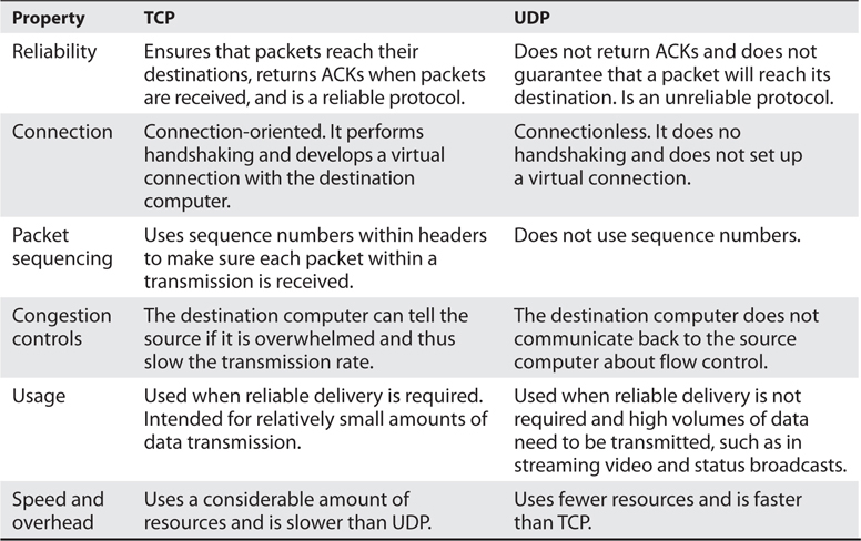
Table 4-1 Major Differences Between TCP and UDP
TCP Handshake
TCP must set up a virtual connection between two hosts before any data is sent. This means the two hosts must agree on certain parameters, data flow, windowing, error detection, and options. These issues are negotiated during the handshaking phase, as shown in Figure 4-13.

Figure 4-13 The TCP three-way handshake
The host that initiates communication sends a synchronous (SYN) packet to the receiver. The receiver acknowledges this request by sending a SYN/ACK packet. This packet translates into, “I have received your request and am ready to communicate with you.” The sending host acknowledges this with an acknowledgment (ACK) packet, which translates into, “I received your acknowledgment. Let’s start transmitting our data.” This completes the handshaking phase, after which a virtual connection is set up, and actual data can now be passed. The connection that has been set up at this point is considered full duplex, which means transmission in both directions is possible using the same transmission line.
If an attacker sends a target system SYN packets with a spoofed address, then the victim system replies to the spoofed address with SYN/ACK packets. Each time the victim system receives one of these SYN packets, it sets aside resources to manage the new connection. If the attacker floods the victim system with SYN packets, eventually the victim system allocates all of its available TCP connection resources and can no longer process new requests. This is a type of DoS that is referred to as a SYN flood. To thwart this type of attack you can use a number of mitigations, the most common of which are described in Internet Engineering Task Force’s (IETF) Request for Comments (RFC) 4987. One of the most effective techniques described in RFC 4987 is the use of SYN caches, which delays the allocation of a socket until the handshake is completed.
Another attack vector we need to understand is TCP sequence numbers. One of the values that is agreed upon during a TCP handshake between two systems is the sequence numbers that will be inserted into the packet headers. Once the sequence number is agreed upon, if a receiving system receives a packet from the sending system that does not have this predetermined value, it will disregard the packet. This means that an attacker cannot just spoof the address of a sending system to fool a receiving system; the attacker has to spoof the sender’s address and use the correct sequence number values. If an attacker can correctly predict the TCP sequence numbers that two systems will use, then she can create packets containing those numbers and fool the receiving system into thinking that the packets are coming from the authorized sending system. She can then take over the TCP connection between the two systems, which is referred to as TCP session hijacking.
Data Structures
As stated earlier, the message is formed and passed to the application layer from a program and sent down through the protocol stack. Each protocol at each layer adds its own information to the message and passes it down to the next layer. This activity is referred to as data encapsulation. As the message is passed down the stack, it goes through a sort of evolution, and each stage has a specific name that indicates what is taking place. When an application formats data to be transmitted over the network, the data is called a message or data. The message is sent to the transport layer, where TCP does its magic on it. The bundle of data is now a segment. The segment is sent to the network layer. The network layer adds routing and addressing, and now the bundle is called a packet. The network layer passes off the packet to the data link layer, which frames the packet with a header and a trailer, and now it is called a frame. Figure 4-14 illustrates these stages.

Figure 4-14 Data goes through its own evolutionary stages as it passes through the layers within the network stack.
EXAM TIP If the message is being transmitted over TCP, it is referred to as a “segment.” If it is being transmitted over UDP, it is referred to as a “datagram.”
Sometimes when an author refers to a segment, she is specifying the stage in which the data is located within the protocol stack. If the literature is describing routers, which work at the network layer, the author might use the word “packet” because the data at this layer has routing and addressing information attached. If an author is describing network traffic and flow control, she might use the word “frame” because all data actually ends up in the frame format before it is put on the network wire.
The important thing here is that you understand the various steps a data package goes through when it moves up and down the protocol stack.
IP Addressing
Each node on a network must have a unique IP address. Today, the most commonly used version of IP is IP version 4 (IPv4), but its addresses are in such high demand that their supply has started to run out. IP version 6 (IPv6) was created to address this shortage. (IPv6 also has many security features built into it that are not part of IPv4.) IPv6 is covered later in this chapter.
IPv4 uses 32 bits for its addresses, whereas IPv6 uses 128 bits; thus, IPv6 provides more possible addresses with which to work. Each address has a host portion and a network portion, and the addresses are grouped into classes and then into subnets. The subnet mask of the address differentiates the groups of addresses that define the subnets of a network. IPv4 address classes are listed in Table 4-2.

Table 4-2 IPv4 Addressing
For any given IP network within an organization, all nodes connected to the network can have different host addresses but a common network address. The host address identifies every individual node, whereas the network address is the identity of the network all the nodes are connected to; therefore, it is the same for each one of them. Any traffic meant for nodes on this network will be sent to the prescribed network address.
A subnet is created from the host portion of an IP address to designate a “sub” network. This allows us to further break the host portion of the address into two or more logical groupings, as shown in Figure 4-15. A network can be logically partitioned to reduce administration headaches, traffic performance, and potentially security. As an analogy, let’s say you work at Toddlers R Us and you are responsible for babysitting 100 toddlers. If you kept all 100 toddlers in one room, you would probably end up crazy. To better manage these kids, you could break them up into groups. The three-year-olds go in the yellow room, the four-year-olds go in the green room, and the five-year-olds go in the blue room. This is what a network administrator would do—break up and separate computer nodes to be able to better control them. Instead of putting them into physical rooms, the administrator puts them into logical rooms (subnets).

Figure 4-15 Subnets create logical partitions.
To continue with our analogy, when you put your toddlers in different rooms, you would have physical barriers that separate them—walls. Network subnetting is not physical; it is logical. This means you would not have physical walls separating your individual subnets, so how do you keep them separate? This is where subnet masks come into play. A subnet mask defines smaller networks inside a larger network, just like individual rooms are defined within a building.
Subnetting allows larger IP ranges to be divided into smaller, logical, and more tangible network segments. Consider an organization with several divisions, such as IT, Accounting, HR, and so on. Creating subnets for each division breaks the networks into logical partitions that route traffic directly to recipients without dispersing data all over the network. This drastically reduces the traffic load across the network, reducing the possibility of network congestion and excessive broadcast packets in the network. Implementing network security policies is also much more effective across logically categorized subnets with a demarcated perimeter, as compared to a large, cluttered, and complex network.
Subnetting is particularly beneficial in keeping down routing table sizes because external routers can directly send data to the actual network segment without having to worry about the internal architecture of that network and getting the data to individual hosts. This job can be handled by the internal routers, which can determine the individual hosts in a subnetted environment and save the external routers the hassle of analyzing all 32 bits of an IP address and just look at the “masked” bits.
TIP You should not have to calculate any subnets for the CISSP exam, but for a better understanding of how this stuff works under the hood, visit http://compnetworking.about.com/od/workingwithipaddresses/a/subnetmask.htm.
If the traditional subnet masks are used, they are referred to as classful or classical IP addresses. If an organization needs to create subnets that do not follow these traditional sizes, then it would use classless IP addresses. This just means a different subnet mask would be used to define the network and host portions of the addresses. After it became clear that available IP addresses were running out as more individuals and corporations participated on the Internet, classless interdomain routing (CIDR) was created. A Class B address range is usually too large for most companies, and a Class C address range is too small, so CIDR provides the flexibility to increase or decrease the class sizes as necessary. CIDR is the method to specify more flexible IP address classes. CIDR is also referred to as supernetting.
NOTE To better understand CIDR, visit the following resource: www.tcpipguide.com/free/t_IPClasslessAddressingClasslessInterDomainRoutingCI.htm.
Although each node has an IP address, people usually refer to their hostname rather than their IP address. Hostnames, such as www.mcgraw-hill.com, are easier for humans to remember than IP addresses, such as 198.105.254.228. However, the use of these two nomenclatures requires mapping between the hostnames and IP addresses because the computer understands only the numbering scheme. This process is addressed in the “Domain Name Service” section later in this chapter.
NOTE IP provides addressing, packet fragmentation, and packet timeouts. To ensure that packets do not continually traverse a network forever, IP provides a Time to Live (TTL) value that is decremented every time the packet passes through a router. IP can also provide a Type of Service (ToS) capability, which means it can prioritize different packets for time-sensitive functions.
IPv6
IPv6, also called IP next generation (IPng), not only has a larger address space than IPv4 to support more IP addresses; it has some capabilities that IPv4 does not and it accomplishes some of the same tasks differently. All of the specifics of the new functions within IPv6 are beyond the scope of this book, but we will look at a few of them, because IPv6 is the way of the future. IPv6 allows for scoped addresses, which enables an administrator to restrict specific addresses for specific servers or file and print sharing, for example. IPv6 has Internet Protocol Security (IPSec) integrated into the protocol stack, which provides end-to-end secure transmission and authentication. IPv6 has more flexibility and routing capabilities and allows for Quality of Service (QoS) priority values to be assigned to time-sensitive transmissions. The protocol offers autoconfiguration, which makes administration much easier, and it does not require network address translation (NAT) to extend its address space.
NAT was developed because IPv4 addresses were running out. Although the NAT technology is extremely useful, it has caused a lot of overhead and transmission problems because it breaks the client/server model that many applications use today. One reason the industry did not jump on the IPv6 bandwagon when it came out years ago is that NAT was developed, which reduced the speed at which IP addresses were being depleted. Although the conversion rate from IPv4 to IPv6 is slow in some parts of the world and the implementation process is quite complicated, the industry is making the shift because of all the benefits that IPv6 brings to the table.
NOTE NAT is covered in the “Network Address Translation” section later in this chapter.
The IPv6 specification, as outlined in RFC 2460, lays out the differences and benefits of IPv6 over IPv4. A few of the differences are as follows:
• IPv6 increases the IP address size from 32 bits to 128 bits to support more levels of addressing hierarchy, a much greater number of addressable nodes, and simpler autoconfiguration of addresses.
• The scalability of multicast routing is improved by adding a “scope” field to multicast addresses. Also, a new type of address called an anycast address is defined, which is used to send a packet to any one of a group of nodes.
• Some IPv4 header fields have been dropped or made optional to reduce the common-case processing cost of packet handling and to limit the bandwidth cost of the IPv6 header. This is illustrated in Figure 4-16.
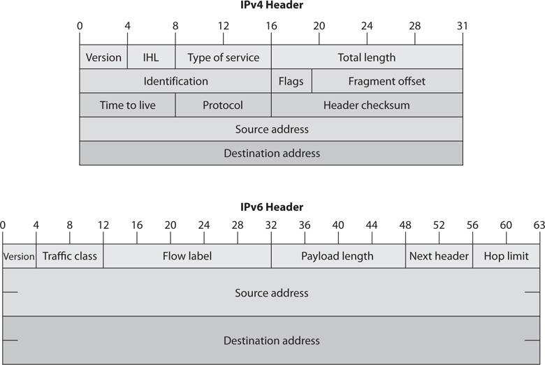
Figure 4-16 IPv4 vs. IPv6 headers
• Changes in the way IP header options are encoded allow for more efficient forwarding, less stringent limits on the length of options, and greater flexibility for introducing new options in the future.
• A new capability is added to enable the labeling of packets belonging to particular traffic “flows” for which the sender requests special handling, such as nondefault QoS or “real-time” service.
• Extensions to support authentication, data integrity, and (optional) data confidentiality are also specified for IPv6.
IPv4 limits packets to 65,535 bytes of payload, and IPv6 extends this size to 4,294,967,295 bytes. These larger packets are referred to as jumbograms and improve performance over high-maximum transmission unit (MTU) links. Currently most of the world still uses IPv4, but IPv6 is being deployed more rapidly. This means that there are “pockets” of networks using IPv4 and “pockets” of networks using IPv6 that still need to communicate. This communication takes place through different tunneling techniques, which either encapsulate IPv6 packets within IPv4 packets or carry out automated address translations. Automatic tunneling is a technique where the routing infrastructure automatically determines the tunnel endpoints so that protocol tunneling can take place without preconfiguration. In the 6to4 tunneling method, the tunnel endpoints are determined by using a well-known IPv4 anycast address on the remote side and embedding IPv4 address data within IPv6 addresses on the local side. Teredo is another automatic tunneling technique that uses UDP encapsulation so that NAT address translations are not affected. Intra-Site Automatic Tunnel Addressing Protocol (ISATAP) treats the IPv4 network as a virtual IPv6 local link, with mappings from each IPv4 address to a link-local IPv6 address.
The 6to4 and Teredo are intersite tunneling mechanisms, and ISATAP is an intrasite mechanism. So the first two are used for connectivity between different networks, and ISATAP is used for connectivity of systems within a specific network. Notice in Figure 4-17 that 6to4 and Teredo are used on the Internet and ISATAP is used within an intranet.

Figure 4-17 Various IPv4 to IPv6 tunneling techniques
While many of these automatic tunneling techniques reduce administration overhead, because network administrators do not have to configure each and every system and network device with two different IP addresses, there are security risks that need to be understood. Many times users and network administrators do not know that automatic tunneling capabilities are enabled, and thus they do not ensure that these different tunnels are secured and/or are being monitored. If you are an administrator of a network and have intrusion detection systems (IDSs), intrusion prevention systems (IPSs), and firewalls that are only configured to monitor and restrict IPv4 traffic, then all IPv6 traffic could be traversing your network insecurely. Attackers use these protocol tunnels and misconfigurations to get past these types of security devices so that malicious activities can take place unnoticed. If you are a user and have a host-based firewall that only understands IPv4 and your operating system has a dual IPv4/IPv6 networking stack, traffic could be bypassing your firewall without being monitored and logged. The use of Teredo can actually open ports in NAT devices that allow for unintended traffic in and out of a network. It is critical that people who are responsible for configuring and maintaining systems and networks understand the differences between IPv4 and IPv6 and how the various tunneling mechanisms work so that all vulnerabilities are identified and properly addressed. Products and software may need to be updated to address both traffic types, proxies may need to be deployed to manage traffic communication securely, IPv6 should be disabled if not needed, and security appliances need to be configured to monitor all traffic types.
Layer 2 Security Standards
As frames pass from one network device to another device, attackers could sniff the data; modify the headers; redirect the traffic; spoof traffic; carry out man-in-the-middle attacks, DoS attacks, and replay attacks; and indulge in other malicious activities. It has become necessary to secure network traffic at the frame level, which is layer 2 of the OSI model.
802.1AE is the IEEE MAC Security standard (MACSec), which defines a security infrastructure to provide data confidentiality, data integrity, and data origin authentication. Where a virtual private network (VPN) connection provides protection at the higher networking layers, MACSec provides hop-by-hop protection at layer 2, as shown in Figure 4-18.
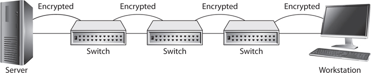
Figure 4-18 MACSec provides layer 2 frame protection.
MACSec integrates security protection into wired Ethernet networks to secure LAN-based traffic. Only authenticated and trusted devices on the network can communicate with each other. Unauthorized devices are prevented from communicating via the network, which helps prevent attackers from installing rogue devices and redirecting traffic between nodes in an unauthorized manner. When a frame arrives at a device that is configured with MACSec, the MACSec Security Entity (SecY) decrypts the frame if necessary and computes an integrity check value (ICV) on the frame and compares it with the ICV that was sent with the frame. If the ICVs match, the device processes the frame. If they do not match, the device handles the frame according to a preconfigured policy, such as discarding it.
The IEEE 802.1AR standard specifies unique per-device identifiers (DevID) and the management and cryptographic binding of a device (router, switch, access point) to its identifiers. A verifiable unique device identity allows establishment of the trustworthiness of devices, and thus facilitates secure device provisioning.
As a security administrator you really only want devices that are allowed on your network to be plugged into your network. But how do you properly and uniquely identify devices? The manufacture serial number is not available for a protocol to review. MAC, hostnames, and IP addresses are easily spoofed. 802.1AR defines a globally unique per-device secure identifier cryptographically bound to the device through the use of public cryptography and digital certificates. These unique hardware-based credentials can be used with the Extensible Authentication Protocol-Transport Layer Security (EAP-TLS) authentication framework. Each device that is compliant with IEEE 802.1AR comes with a single built-in initial secure device identity (iDevID). The iDevID is an instance of the general concept of a DevID, which is intended to be used with authentication protocols such as EAP, which is supported by IEEE 802.1X.
So 802.1AR provides a unique ID for a device. 802.1AE provides data encryption, integrity, and origin authentication functionality. 802.1AF carries out key agreement functions for the session keys used for data encryption. Each of these standards provides specific parameters to work within an 802.1X EAP-TLS framework, as shown in Figure 4-19.

Figure 4-19 Layer 2 security protocols
As Figure 4-19 shows, when a new device is installed on the network, it cannot just start communicating with other devices, receive an IP address from a Dynamic Host Configuration Protocol (DHCP) server, resolve names with the DNS server, etc. The device cannot carry out any network activity until it is authorized to do so. So 802.1X port authentication kicks in, which means that only authentication data is allowed to travel from the new device to the authenticating server. The authentication data is the digital certificate and hardware identity associated with that device (802.1AR), which is processed by EAP-TLS. Once the device is authenticated, usually by a Remote Authentication Dial-In User Server (RADIUS) server, encryption keying material is negotiated and agreed upon between surrounding network devices. Once the keying material is installed, then data encryption and frame integrity checking can take place (802.1AE) as traffic goes from one network device to the next.
These IEEE standards are new and evolving and at different levels of implementation by various vendors. One way the unique hardware identity and cryptographic material are embedded in new network devices is through the use of a Trusted Platform Module (TPM; described in Chapter 3).
Converged Protocols
Converged protocols are those that started off independent and distinct from one another but over time converged to become one. How is this possible? Think about the phone and data networks. Once upon a time, these were two different entities and each had its own protocols and transmission media. For a while, in the 1990s, data networks sometimes rode over voice networks using data modems. This was less than ideal, which is why we flipped it around and started using data networks as the carrier for voice communications. Over time, the voice protocols converged onto the data protocols, which paved the way for Voice over IP (VoIP).
Technically, the term converged implies that the two protocols became one. Oftentimes, however, the term is used to describe cases in which one protocol was originally independent of another, but over time started being encapsulated (or tunneled) within that other one. The following are examples of converged protocols:
• Fibre Channel over Ethernet (FCoE) This is a protocol encapsulation that allows Fibre Channel (FC) frames to ride over Ethernet networks. FC was developed by ANSI in 1988 as a way to connect supercomputers using optical fibers. Nowadays FCoE is used in some storage area networks (SANs), but is not common.
• Multiprotocol Label Switching (MPLS) MPLS was originally developed to improve routing performance, but is frequently used for its ability to create VPNs over a variety of layer 2 protocols. It has elements of both layer 2 (data link) and layer 3 (networking), and so is commonly referred to as a layer 2.5 protocol. MPLS is considered a converged protocol because it can encapsulate any higher-layer protocol and tunnel it over a variety of links.
• Internet Small Computer System Interface (iSCSI) iSCSI encapsulates SCSI data in TCP segments. SCSI is a set of technologies that allows peripherals to be connected to computers. The problem with the original SCSI was that it has limited range, which means that connecting a remote peripheral (e.g., camera or storage device) is not normally possible. The solution was to let SCSI ride on TCP segments so a peripheral device could be literally anywhere in the world and still appear as local to a computer.
IP convergence, which addresses a specific type of converged protocols, is the transition of services from disparate transport media and protocols to IP. The earlier example of VoIP is also a case of IP convergence. It is not hard to see that IP has emerged as the dominant standard for networking, so it makes sense that any new protocols would leverage this existing infrastructure rather than create a separate one.
Types of Transmission
Physical data transmission can happen in different ways (analog or digital); can use different synchronization schemes (synchronous or asynchronous); can use either one sole channel over a transmission medium (baseband) or several different channels over a transmission medium (broadband); and can take place as electrical voltage, radio wave, or optical signals. These transmission types and their characteristics are described in the following sections.
Analog and Digital
A signal is just some way of moving information in a physical format from one point to another point. You can signal a message to another person through nodding your head, waving your hand, or giving a wink. Somehow you are transmitting data to that person through your signaling method. In the world of technology, we have specific carrier signals that are in place to move data from one system to another system. The carrier signal is like a horse, which takes a rider (data) from one place to another place. Data can be transmitted through analog or digital signaling formats. If you are moving data through an analog transmission technology (e.g., radio), then the data is represented by the characteristics of the waves that are carrying it. For example, a radio station uses a transmitter to put its data (music) onto a radio wave that will travel all the way to your antenna. The information is stripped off by the receiver in your radio and presented to you in its original format—a song. The data is encoded onto the carrier signal and is represented by various amplitude and frequency values, as shown in Figure 4-20.

Figure 4-20 Analog signals are measured in amplitude and frequency, whereas digital signals represent binary digits as electrical pulses.
Data being represented in wave values (analog) is different from data being represented in discrete voltage values (digital). As an analogy, compare an analog clock and a digital clock. An analog clock has hands that continuously rotate on the face of the clock. To figure out what time it is, you have to interpret the position of the hands and map their positions to specific values. So you have to know that if the large hand is on the number 1 and the small hand is on the number 6, this actually means 1:30. The individual and specific location of the hands corresponds to a value. A digital clock does not take this much work. You just look at it and it gives you a time value in the format of number:number. There is no mapping work involved with a digital clock because it provides you with data in clear-cut formats.
An analog clock can represent different values as the hands move forward—1:35 and 1 second, 1:35 and 2 seconds, 1:35 and 3 seconds. Each movement of the hands represents a specific value just like the individual data points on a wave in an analog transmission. A digital clock provides discrete values without having to map anything. The same is true with digital transmissions: the value is always either a 1 or a 0—no need for mapping to find the actual value.
Computers have always worked in a binary and digital manner (1 or 0). When our telecommunication infrastructure was purely analog, each system that needed to communicate over a telecommunication line had to have a modem (modulator/demodulator), which would modulate the digital data into an analog signal. The sending system’s modem would modulate the data on to the signal, and the receiving system’s modem would demodulate the data off the signal.
Digital signals are more reliable than analog signals over a long distance and provide a clear-cut and efficient signaling method because the voltage is either on (1) or not on (0), compared to interpreting the waves of an analog signal. Extracting digital signals from a noisy carrier is relatively easy. It is difficult to extract analog signals from background noise because the amplitudes and frequencies of the waves slowly lose form. This is because an analog signal could have an infinite number of values or states, whereas a digital signal exists in discrete states. A digital signal is a square wave, which does not have all of the possible values of the different amplitudes and frequencies of an analog signal. Digital systems can implement compression mechanisms to increase data throughput, provide signal integrity through repeaters that “clean up” the transmissions, and multiplex different types of data (voice, data, video) onto the same transmission channel. As we will see in following sections, most telecommunication technologies have moved from analog to digital transmission technologies.
EXAM TIP Bandwidth refers to the number of electrical pulses that can be transmitted over a link within a second, and these electrical pulses carry individual bits of information. Bandwidth is the data transfer capability of a connection and is commonly associated with the amount of available frequencies and speed of a link. Data throughput is the actual amount of data that can be carried over this connection. Data throughput values can be higher than bandwidth values if compression mechanisms are implemented. But if links are highly congested or there are interference issues, the data throughput values can be lower. Both bandwidth and data throughput are measured in bits per second.
Asynchronous and Synchronous
Analog and digital transmission technologies deal with the characteristics of the physical carrier on which data is moved from one system to another. Asynchronous and synchronous transmission types are similar to the cadence rules we use for conversation synchronization. Asynchronous and synchronous network technologies provide synchronization rules to govern how systems communicate to each other. If you have ever spoken over a satellite phone, you have probably experienced problems with communication synchronization. You and the other person talking do not allow for the necessary delay that satellite communication requires, so you “speak over” one another. Once you figure out the delay in the connection, you resynchronize your timing so that only one person’s data (voice) is transmitting at one time so that each person can properly understand the full conversation. Proper pauses frame your words in a way to make them understandable.
Synchronization through communication also happens when we write messages to each other. Properly placed commas, periods, and semicolons provide breaks in text so that the person reading the message can better understand the information. If you see “stickwithmekidandyouwillweardiamonds” without the proper punctuation, it is more difficult for you to understand. This is why we have grammar rules. If someone writes you a letter starting from the bottom and right side of a piece of paper and you do not know this, you will not be able to read his message properly.
Technological communication protocols also have their own grammar and synchronization rules when it comes to the transmission of data. If two systems are communicating over a network protocol that employs asynchronous timing, then start and stop bits are used. The sending system sends a “start” bit, then sends its character, and then sends a “stop” bit. This happens for the whole message. The receiving system knows when a character is starting and stopping; thus, it knows how to interpret each character of the message. This is akin to our previous example of using punctuation marks in written communications to convey pauses. If the systems are communicating over a network protocol that uses synchronous timing, then no start and stop bits are added. The whole message is sent without artificial breaks, but with a common timing signal that allows the receiver to know how to interpret the information without these bits. This is similar to our satellite phone example in which we use a timing signal (i.e., we count off seconds in our head) to ensure we don’t step all over the other person’s speech.
If two systems are going to communicate using a synchronous transmission technology, they do not use start and stop bits, but the synchronization of the transfer of data takes place through a timing sequence, which is initiated by a clock pulse.
It is the data link protocol that has the synchronization rules embedded into it. So when a message goes down a system’s network stack, if a data link protocol, such as High-level Data Link Control (HDLC, described later in the chapter), is being used, then a clocking sequence is in place. (The receiving system has to also be using this protocol so it can interpret the data.) If the message is going down a network stack and a protocol such as Asynchronous Transfer Mode (ATM) is at the data link layer, then the message is framed with start and stop indicators.
Data link protocols that employ synchronous timing mechanisms are commonly used in environments that have systems that transfer large amounts of data in a predictable manner (i.e., mainframe environment). Environments that contain systems that send data in a nonpredictable manner (i.e., Internet connections) commonly have systems with protocols that use asynchronous timing mechanisms.
So, synchronous communication protocols transfer data as a stream of bits instead of framing it in start and stop bits. The synchronization can happen between two systems using a clocking mechanism, or a signal can be encoded into the data stream to let the receiver synchronize with the sender of the message. This synchronization needs to take place before the first message is sent. The sending system can transmit a digital clock pulse to the receiving system, which translates into, “We will start here and work in this type of synchronization scheme.” Many modern bulk communication systems, such as high-bandwidth satellite links, use Global Positioning System (GPS) clock signals to synchronize their communications without the need to include a separate channel for timing.
Broadband and Baseband
So analog transmission means that data is being moved as waves, and digital transmission means that data is being moved as discrete electric pulses. Synchronous transmission means that two devices control their conversations with a clocking mechanism, and asynchronous means that systems use start and stop bits for communication synchronization. Now let’s look at how many individual communication sessions can take place at one time.
A baseband technology uses the entire communication channel for its transmission, whereas a broadband technology divides the communication channel into individual and independent subchannels so that different types of data can be transmitted simultaneously. Baseband permits only one signal to be transmitted at a time, whereas broadband carries several signals over different subchannels. For example, a coaxial cable TV (CATV) system is a broadband technology that delivers multiple television channels over the same cable. This system can also provide home users with Internet access, but this data is transmitted at a different frequency range than the TV channels.
As an analogy, baseband technology only provides a one-lane highway for data to get from one point to another point. A broadband technology provides a data highway made up of many different lanes, so that not only can more data be moved from one point to another point, but different types of data can travel over the individual lanes.
Any transmission technology that “chops up” one communication channel into multiple channels is considered broadband. The communication channel is usually a specific range of frequencies, and the broadband technology provides delineation between these frequencies and techniques on how to modulate the data onto the individual subchannels. To continue with our analogy, we could have one large highway that could fit eight individual lanes—but unless we have something that defines these lanes and there are rules for how these lanes are used, this is a baseband connection. If we take the same highway and lay down painted white lines, traffic signs, on and off ramps, and rules that drivers have to follow, now we are talking about broadband.
A digital subscriber line (DSL) uses one single phone line and constructs a set of high-frequency channels for Internet data transmissions. A cable modem uses the available frequency spectrum that is provided by a cable TV carrier to move Internet traffic to and from a household. Mobile broadband devices implement individual channels over a cellular connection, and Wi-Fi broadband technology moves data to and from an access point over a specified frequency set. We will cover these technologies in more depth throughout the chapter, but for now you just need to understand that they are different ways of cutting up one channel into individual channels for higher data transfer and that they provide the capability to move different types of traffic at the same time.
Next, let’s look at the different ways we connect the many devices that make up small and large networks around the world.
Cabling
Electrical signals travel as currents through cables and can be negatively affected by many factors within the environment, such as motors, fluorescent lighting, magnetic forces, and other electrical devices. These items can corrupt the data as it travels through the cable, which is why cable standards are used to indicate cable type, shielding, transmission rates, and maximum distance a particular type of cable can be used.
Cabling has bandwidth values associated with it, which is different from data throughput values. Although these two terms are related, they are indeed different. The bandwidth of a cable indicates the highest frequency range it uses—for instance, 10Base-T uses 10 MHz, 100Base-TX uses 80 MHz, and 1000Base-T uses 100 MHz. This is different from the actual amount of data that can be pushed through a cable. The data throughput rate is the actual amount of data that goes through the wire after compression and encoding have been used. 10Base-T has a data rate of 10 Mbps, 100Base-TX has a data rate of 100 Mbps, and 1000Base-T has a data rate of 1 Gbps. The bandwidth can be thought of as the size of the pipe, and the data throughput rate is the actual amount of data that travels per second through that pipe.
Bandwidth is just one of the characteristics we will look at as we cover various cabling types in the following sections.
Coaxial Cable
Coaxial cable has a copper core that is surrounded by a shielding layer and grounding wire, as shown in Figure 4-21. This is all encased within a protective outer jacket. Compared to twisted-pair cable, coaxial cable is more resistant to electromagnetic interference (EMI), provides a higher bandwidth, and supports the use of longer cable lengths. So, why is twisted-pair cable more popular? Twisted-pair cable is cheaper and easier to work with, and the move to switched environments that provide hierarchical wiring schemes has overcome the cable-length issue of twisted-pair cable.

Figure 4-21 Coaxial cable
Coaxial cabling is used as a transmission line for radio frequency signals. If you have cable TV, you have coaxial cabling entering your house and the back of your TV. The various TV channels are carried over different radio frequencies. We will cover cable modems later in this chapter, which is a technology that allows you to use some of the “empty” TV frequencies for Internet connectivity.
Twisted-Pair Cable
Twisted-pair cabling has insulated copper wires surrounded by an outer protective jacket. If the cable has an outer foil shielding, it is referred to as shielded twisted pair (STP), which adds protection from radio frequency interference (RFI) and EMI. Twisted-pair cabling, which does not have this extra outer shielding, is called unshielded twisted pair (UTP).
The twisted-pair cable contains copper wires that twist around each other, as shown in Figure 4-22. This twisting of the wires protects the integrity and strength of the signals they carry. Each wire forms a balanced circuit, because the voltage in each pair uses the same amplitude, just with opposite phases. The tighter the twisting of the wires, the more resistant the cable is to interference and attenuation. UTP has several categories of cabling, each of which has its own unique characteristics.

Figure 4-22 Twisted-pair cabling uses copper wires.
The twisting of the wires, the type of insulation used, the quality of the conductive material, and the shielding of the wire determine the rate at which data can be transmitted. The UTP ratings indicate which of these components were used when the cables were manufactured. Some types are more suitable and effective for specific uses and environments. Table 4-3 lists the cable ratings.

Table 4-3 UTP Cable Ratings
Copper cable has been around for many years. It is inexpensive and easy to use. A majority of the telephone systems today use copper cabling with the rating of voice grade. Twisted-pair wiring is the preferred network cabling, but it also has its drawbacks. Copper actually resists the flow of electrons, which causes a signal to degrade after it has traveled a certain distance. This is why cable lengths are recommended for copper cables; if these recommendations are not followed, a network could experience signal loss and data corruption. Copper also radiates energy, which means information can be monitored and captured by intruders. UTP is the least secure networking cable compared to coaxial and fiber. If a company requires higher speed, higher security, and cables to have longer runs than what is allowed in copper cabling, fiber-optic cable may be a better choice.
Fiber-Optic Cable
Twisted-pair cable and coaxial cable use copper wires as their data transmission media, but fiber-optic cable uses a type of glass that carries light waves, which represent the data being transmitted. The glass core is surrounded by a protective cladding, which in turn is encased within an outer jacket.
Because it uses glass, fiber-optic cabling has higher transmission speeds that allow signals to travel over longer distances. Fiber cabling is not as affected by attenuation and EMI when compared to cabling that uses copper. It does not radiate signals, as does UTP cabling, and is difficult to eavesdrop on; therefore, fiber-optic cabling is much more secure than UTP, STP, or coaxial.
Using fiber-optic cable sounds like the way to go, so you might wonder why you would even bother with UTP, STP, or coaxial. Unfortunately, fiber-optic cable is expensive and difficult to work with. It is usually used in backbone networks and environments that require high data transfer rates. Most networks use UTP and connect to a backbone that uses fiber.
NOTE The price of fiber and the cost of installation have been continuously decreasing, while the demand for more bandwidth only increases. More organizations and service providers are installing fiber directly to the end user.
Cabling Problems
Cables are extremely important within networks, and when they experience problems, the whole network could experience problems. This section addresses some of the more common cabling issues many networks experience.
Noise
Noise on a line is usually caused by surrounding devices or by characteristics of the wiring’s environment. Noise can be caused by motors, computers, copy machines, fluorescent lighting, and microwave ovens, to name a few. This background noise can combine with the data being transmitted over the cable and distort the signal, as shown in Figure 4-23. The more noise there is interacting with the cable, the more likely the receiving end will not receive the data in the form originally transmitted.

Figure 4-23 Background noise can merge with an electronic signal and alter the signal’s integrity.
Attenuation
Attenuation is the loss of signal strength as it travels. This is akin to rolling a ball down the floor; as it travels, air causes resistance that slows it down and eventually stops it. In the case of electricity, the metal in the wire also offers resistance to the flow of electricity. Though some materials such as copper and gold offer very little resistance, it is still there. The longer a wire, the more attenuation occurs, which causes the signal carrying the data to deteriorate. This is why standards include suggested cable-run lengths.
The effects of attenuation increase with higher frequencies; thus, 100Base-TX at 80 MHz has a higher attenuation rate than 10Base-T at 10 MHz. This means that cables used to transmit data at higher frequencies should have shorter cable runs to ensure attenuation does not become an issue.
If a networking cable is too long, attenuation will become a problem. Basically, the data is in the form of electrons, and these electrons have to “swim” through a copper wire. However, this is more like swimming upstream, because there is a lot of resistance on the electrons working in this media. After a certain distance, the electrons start to slow down and their encoding format loses form. If the form gets too degraded, the receiving system cannot interpret them any longer. If a network administrator needs to run a cable longer than its recommended segment length, she needs to insert a repeater or some type of device that will amplify the signal and ensure it gets to its destination in the right encoding format.
Attenuation can also be caused by cable breaks and malfunctions. This is why cables should be tested. If a cable is suspected of attenuation problems, cable testers can inject signals into the cable and read the results at the end of the cable.
Crosstalk
Crosstalk is a phenomenon that occurs when electrical signals of one wire spill over to the signals of another wire. When electricity flows through a wire, it generates a magnetic field around it. If another wire is close enough, the second wire acts as an antenna that turns this magnetic field into an electric current. When the different electrical signals mix, their integrity degrades and data corruption can occur. UTP is much more vulnerable to crosstalk than STP or coaxial because it does not have extra layers of shielding to help protect against it.
Fire Rating of Cables
Just as buildings must meet certain fire codes, so must wiring schemes. A lot of companies string their network wires in drop ceilings—the space between the ceiling and the next floor—or under raised floors. This hides the cables and prevents people from tripping over them. However, when wires are strung in places like this, they are more likely to catch on fire without anyone knowing about it. Some cables produce hazardous gases when on fire that would spread throughout the building quickly. Network cabling that is placed in these types of areas, called plenum space, must meet a specific fire rating to ensure it will not produce and release harmful chemicals in case of a fire. A ventilation system’s components are usually located in this plenum space, so if toxic chemicals were to get into that area, they could easily spread throughout the building in minutes.
Nonplenum cables usually have a polyvinyl chloride (PVC) jacket covering, whereas plenum-rated cables have jacket covers made of fluoropolymers. When setting up a network or extending an existing network, it is important you know which wire types are required in which situation.
Cables should be installed in unexposed areas so they are not easily tripped over, damaged, or eavesdropped upon. The cables should be strung behind walls and in the protected spaces as in dropped ceilings. In environments that require extensive security, wires can be encapsulated within pressurized conduits so if someone attempts to access a wire, the pressure of the conduit will change, causing an alarm to sound and a message to be sent to the security staff. A better approach to high-security requirements is probably to use fiber-optic cable, which is much more difficult to covertly tap.
NOTE While a lot of the world’s infrastructure is wired and thus uses one of these types of cables, remember that a growing percentage of our infrastructure is not wired. We will cover these technologies later in the chapter (mobile, wireless, satellite, etc.).
Networking Foundations
Networking has made amazing advances in just a short period of time. In the beginning of the Computer Age, mainframes were the name of the game. They were isolated powerhouses, and many had “dumb” terminals hanging off them. However, this was not true networking. In the late 1960s and early 1970s, some technical researchers came up with ways of connecting all the mainframes and Unix systems to enable them to communicate. This marked the Internet’s baby steps.
Microcomputers evolved and were used in many offices and work areas. Slowly, dumb terminals got a little smarter and more powerful as users needed to share office resources. And bam! Ethernet was developed, which allowed for true networking. There was no turning back after this.
While access to shared resources was a major drive in the evolution of networking, today the infrastructure that supports these shared resources and the services these components provide is really the secret to the secret sauce. As we will see, networks are made up of routers, switches, web servers, proxies, firewalls, name resolution technologies, protocols, IDS, IPS, storage systems, antimalware software, virtual private networks, demilitarized zones (DMZs), data loss prevention solutions, e-mail systems, cloud computing, web services, authentication services, redundant technologies, public key infrastructure, private branch exchange (PBX), and more. While functionality is critical, there are other important requirements that need to be understood when architecting a network, such as scalability, redundancy, performance, security, manageability, and maintainability.
Infrastructure provides foundational capabilities that support almost every aspect of our lives. When most people think of technology, they focus on the end systems that they interact with—laptops, mobile phones, tablet PCs, workstations, etc.—or the applications they use, such as e-mail, fax, Facebook, websites, instant messaging, Twitter, and online banking. Most people do not even give a thought to how this stuff works under the covers, and many people do not fully realize all the other stuff that is dependent upon technology: medical devices, critical infrastructure, weapon systems, transportation, satellites, telephony, etc. People say it is love that makes the world go around, but let them experience one day without the Internet. We are all more dependent upon the Matrix than we fully realize, and as security professionals we need to not only understand the Matrix, but also secure it.
Network Topology
The arrangement of computers and devices is called a network topology. Topology refers to the manner in which a network is physically connected and shows the layout of resources and systems. A difference exists between the physical network topology and the logical topology. A network can be configured as a physical star but work logically as a ring, as in the Token Ring technology.
The best topology for a particular network depends on such things as how nodes are supposed to interact; which protocols are used; the types of applications that are available; the reliability, expandability, and physical layout of a facility; existing wiring; and the technologies implemented. The wrong topology or combination of topologies can negatively affect the network’s performance, productivity, and growth possibilities.
This section describes the basic types of network topologies. Most networks are much more complex and are usually implemented using a combination of topologies.
Ring Topology
A ring topology has a series of devices connected by unidirectional transmission links, as shown in Figure 4-24. These links form a closed loop and do not connect to a central system, as in a star topology (discussed later). In a physical ring formation, each node is dependent upon the preceding nodes. In simple networks, if one system fails, all other systems could be negatively affected because of this interdependence. Today, most networks have redundancy in place or other mechanisms that will protect a whole network from being affected by just one workstation misbehaving, but one disadvantage of using a ring topology is that this possibility exists.

Figure 4-24 A ring topology forms a closed-loop connection.
Bus Topology
In a simple bus topology, a single cable runs the entire length of the network. Nodes are attached to the network through drop points on this cable. Data communications transmit the length of the medium, and each packet transmitted has the capability of being “looked at” by all nodes. Each node decides to accept or ignore the packet, depending upon the packet’s destination address.
Bus topologies are of two main types: linear and tree. The linear bus topology has a single cable with nodes attached. A tree topology has branches from the single cable, and each branch can contain many nodes.
In simple implementations of a bus topology, if one workstation fails, other systems can be negatively affected because of the degree of interdependence. In addition, because all nodes are connected to one main cable, the cable itself becomes a potential single point of failure. Traditionally, Ethernet uses bus and star topologies.
Star Topology
In a star topology, all nodes connect to a central device such as a switch. Each node has a dedicated link to the central device. The central device needs to provide enough throughput that it does not turn out to be a detrimental bottleneck for the network as a whole. Because a central device is required, it is a potential single point of failure, so redundancy may need to be implemented. Switches can be configured in flat or hierarchical implementations so larger organizations can use them.
When one workstation fails on a star topology, it does not affect other systems, as in the ring or bus topologies. In a star topology, each system is not as dependent on others as it is dependent on the central connection device. This topology generally requires less cabling than other types of topologies. As a result, cut cables are less likely, and detecting cable problems is an easier task.
Not many networks use true linear bus and ring topologies anymore. A ring topology can be used for a backbone network, but most networks are constructed in a star topology because it enables the network to be more resilient and not as affected if an individual node experiences a problem.
Mesh Topology
In a mesh topology, all systems and resources are connected to each other in a way that does not follow the uniformity of the previous topologies, as shown in Figure 4-25. This arrangement is usually a network of interconnected routers and switches that provides multiple paths to all the nodes on the network. In a full mesh topology, every node is directly connected to every other node, which provides a great degree of redundancy. In a partial mesh topology, every node is not directly connected. The Internet is an example of a partial mesh topology.

Figure 4-25 In a mesh topology, each node is connected to all other nodes, which provides for redundant paths.
A summary of the different network topologies and their important characteristics is provided in Table 4-4.

Table 4-4 Summary of Network Topologies
Media Access Technologies
The physical topology of a network is the lower layer, or foundation, of a network. It determines what type of media will be used and how the media will be connected between different systems. Media access technologies deal with how these systems communicate over this media and are usually represented in protocols, NIC drivers, and interfaces. LAN access technologies set up the rules of how computers will communicate on a network, how errors are handled, the maximum transmission unit (MTU) size of frames, and much more. These rules enable all computers and devices to communicate and recover from problems, and enable users to be productive in accomplishing their networking tasks. Each participating entity needs to know how to communicate properly so all other systems will understand the transmissions, instructions, and requests. This is taken care of by the LAN media access technology.
NOTE An MTU is a parameter that indicates how much data a frame can carry on a specific network. Recall that a data frame is the data encapsulation structure that exists at layer 2 (data link) of the OSI model. Different types of network technologies may require different MTU sizes, which is why frames are sometimes fragmented.
These technologies reside at the data link layer of the OSI model. Remember that as a message is passed down through a network stack, it is encapsulated by the protocols and services at each layer. When the data message reaches the data link layer, the protocol at this layer adds the necessary headers and trailers that will allow the message to traverse a specific type of network (Ethernet, Token Ring, FDDI, etc.) The protocol and network driver work at the data link layer, and the NIC works at the physical layer, but they have to work together and be compatible. If you install a new server on an Ethernet network, you must implement an Ethernet NIC and driver.
The LAN-based technologies we will cover in the next sections are Ethernet, Token Ring, and FDDI. We will cover wireless networking technologies later in the chapter.
A local area network (LAN) is a network that provides shared communication and resources in a relatively small area. What defines a LAN, as compared to a WAN, depends on the physical medium, encapsulation protocols, and media access technology. For example, a LAN could use 10Base-T cabling, TCP/IP protocols, and Ethernet media access technology, and it could enable users who are in the same local building to communicate. A WAN, on the other hand, could use fiber-optic cabling, the L2TP encapsulation protocol, and ATM media access technology and could enable users from one building to communicate with users in another building in another state (or country). A WAN connects LANs over great distances geographically. Most of the differences between these technologies are found at the data link layer.
Token Passing A token is a 24-bit control frame used to control which computers communicate at what intervals. The token is passed from computer to computer, and only the computer that has the token can actually put frames onto the wire. The token grants a computer the right to communicate. The token contains the data to be transmitted and source and destination address information. When a system has data it needs to transmit, it has to wait to receive the token. The computer then connects its message to the token and puts it on the wire. Each computer checks this message to determine whether it is addressed to it, which continues until the destination computer receives the message. The destination computer makes a copy of the message and flips a bit to tell the source computer it did indeed get its message. Once this gets back to the source computer, it removes the frames from the network. The destination computer makes a copy of the message, but only the originator of the message can remove the message from the token and the network.
If a computer that receives the token does not have a message to transmit, it sends the token to the next computer on the network. An empty token has a header, data field, and trailer, but a token that has an actual message has a new header, destination address, source address, and a new trailer.
This type of media-sharing method is used by Token Ring and FDDI technologies.
NOTE Some applications and network protocols work better if they can communicate at determined intervals, instead of “whenever the data arrives.” In token-passing technologies, traffic arrives in this type of deterministic nature because not all systems can communicate at one time; only the system that has control of the token can communicate.
CSMA Ethernet protocols define how nodes are to communicate, recover from errors, and access the shared network cable. Ethernet uses CSMA to provide media-sharing capabilities. There are two distinct types of CSMA: CSMA/CD and CSMA/CA.
A transmission is called a carrier, so if a computer is transmitting frames, it is performing a carrier activity. When computers use the carrier sense multiple access with collision detection (CSMA/CD) protocol, they monitor the transmission activity, or carrier activity, on the wire so they can determine when would be the best time to transmit data. Each node monitors the wire continuously and waits until the wire is free before it transmits its data. As an analogy, consider several people gathered in a group talking here and there about this and that. If a person wants to talk, she usually listens to the current conversation and waits for a break before she proceeds to talk. If she does not wait for the first person to stop talking, she will be speaking at the same time as the other person, and the people around them may not be able to understand fully what each is trying to say.
When using the CSMA/CD access method, computers listen for the absence of a carrier tone on the cable, which indicates that no other system is transmitting data. If two computers sense this absence and transmit data at the same time, a collision can take place. A collision happens when two or more frames collide, which most likely corrupts both frames. If a computer puts frames on the wire and its frames collide with another computer’s frames, it will abort its transmission and alert all other stations that a collision just took place. All stations will execute a random collision timer to force a delay before they attempt to transmit data. This random collision timer is called the back-off algorithm.
NOTE Collisions are usually reduced by dividing a network with routers or switches.
Carrier sense multiple access with collision avoidance (CSMA/CA) is a medium-sharing method in which each computer signals its intent to transmit data before it actually does so. This tells all other computers on the network not to transmit data right now because doing so could cause a collision. Basically, a system listens to the shared medium to determine whether it is busy or free. Once the system identifies that the “coast is clear” and it can put its data on the wire, it sends out a broadcast to all other systems, telling them it is going to transmit information. It is similar to saying, “Everyone shut up. I am going to talk now.” Each system will wait a period of time before attempting to transmit data to ensure collisions do not take place. The wireless LAN technology 802.11 uses CSMA/CA for its media access functionality.
NOTE When there is just one transmission medium (i.e., UTP cable) that has to be shared by all nodes and devices in a network, this is referred to as a contention-based environment. Each system has to “compete” to use the transmission line, which can cause contention.
Collision Domains As indicated in the preceding section, a collision occurs on Ethernet networks when two computers transmit data at the same time. Other computers on the network detect this collision because the overlapping signals of the collision increase the voltage of the signal above a specific threshold. The more devices on a contention-based network, the more likely collisions will occur, which increases network latency (data transmission delays). A collision domain is a group of computers that are contending, or competing, for the same shared communication medium.
An unacceptable amount of collisions can be caused by a highly populated network, a damaged cable or connector, too many repeaters, or cables that exceed the recommended length. If a cable is longer than what is recommended by the Ethernet specification, two computers on opposite ends of the cable may transmit data at the same time. Because the computers are so far away from each other, they may both transmit data and not realize that a collision took place. The systems then go merrily along with their business, unaware that their packets have been corrupted. If the cable is too long, the computers may not listen long enough for evidence of a collision. If the destination computers receive these corrupted frames, they then have to send a request to the source system to retransmit the message, causing even more traffic.
These types of problems are dealt with mainly by implementing collision domains. An Ethernet network has broadcast and collision domains. One subnet will be on the same broadcast and collision domain if it is not separated by routers or bridges. If the same subnet is divided by bridges, the bridges can enable the broadcast traffic to pass between the different parts of a subnet, but not the collisions, as shown in Figure 4-26. This is how collision domains are formed. Isolating collision domains reduces the amount of collisions that take place on a network and increases its overall performance.

Figure 4-26 Collision domains within one broadcast domain
EXAM TIP Broadcast domains are sets of computing nodes that all receive a layer 2 broadcast frame. These are normally all nodes that are interconnected by switches, hubs, or bridges but with no routers in between them. Collision domains are sets of computing nodes that may produce collisions when they transmit data. These are normally nodes connected by hubs, repeaters, or wireless access points.
Another benefit of restricting and controlling broadcast and collision domains is that it makes sniffing the network and obtaining useful information more difficult for an intruder as he traverses the network. A useful tactic for attackers is to install a Trojan horse that sets up a network sniffer on the compromised computer. The sniffer is usually configured to look for a specific type of information, such as usernames and passwords. If broadcast and collision domains are in effect, the compromised system will have access only to the broadcast and collision traffic within its specific subnet or broadcast domain. The compromised system will not be able to listen to traffic on other broadcast and collision domains, and this can greatly reduce the amount of traffic and information available to an attacker.
Polling The third type of media-sharing method is polling. In an environment where a polling LAN media access and sharing method is used, some systems are configured as primary stations and others are configured as secondary stations. At predefined intervals, the primary station asks the secondary station if it has anything to transmit. This is the only time a secondary station can communicate.
Polling is a method of monitoring multiple devices and controlling network access transmission. If polling is used to monitor devices, the primary device communicates with each secondary device in an interval to check its status. The primary device then logs the response it receives and moves on to the next device. If polling is used for network access, the primary station asks each device if it has something to communicate to another device. Network access transmission polling is used mainly with mainframe environments.
So remember that there are different media access technologies (Ethernet, Token Ring, FDDI, Wi-Fi) that work at the data link and physical layers of the OSI model. These technologies define the data link protocol, NIC and NIC driver specifications, and media interface requirements. These individual media access technologies have their own way of allowing systems to share the one available network transmission medium—Ethernet uses CSMACD, Token Ring uses tokens, FDDI uses tokens, Wi-Fi uses CSMACA, and mainframe media access technology uses polling. The media-sharing technology is a subcomponent of the media access technology.
The term “local” in the context of a LAN refers not so much to the geographical area as to the limitations of a LAN with regard to the shared medium, the number of devices and computers that can be connected to it, the transmission rates, the types of cable that can be used, and the compatible devices. If a network administrator develops a very large LAN that would more appropriately be multiple LANs, too much traffic could result in a big performance hit, or the cabling could be too long, in which case attenuation (signal loss) becomes a factor. Environments where there are too many nodes, routers, and switches may be overwhelmed, and administration of these networks could get complex, which opens the door for errors, collisions, and security holes. The network administrator should follow the specifications of the technology he is using, and once he has maxed out these numbers, he should consider implementing two or more LANs instead of one large LAN. LANs are defined by their physical topologies, data link layer technologies, protocols, and devices used. The following sections cover these topics and how they interrelate.
Ethernet
Ethernet is a set of technologies that enables several devices to communicate on the same network. Ethernet usually uses a bus or star topology. If a linear bus topology is used, all devices connect to one cable. If a star topology is used, each device is connected to a cable that is connected to a centralized device, such as a switch. Ethernet was developed in the 1970s, became commercially available in 1980, and was officially defined through the IEEE 802.3 standard.
Ethernet has seen quite an evolution in its short history, from purely coaxial cable installations that worked at 10 Mbps to mostly Category 5 twisted-pair cable that works at speeds of 100 Mbps, 1,000 Mbps (1 Gbps), and 10 Gbps.
Ethernet is defined by the following characteristics:
• Contention-based technology (all resources use the same shared communication medium)
• Uses broadcast and collision domains
• Uses the carrier sense multiple access with collision detection (CSMA/CD) access method
• Supports full-duplex communication
• Can use coaxial, twisted-pair, or fiber-optic cabling types
• Is defined by standard IEEE 802.3
Ethernet addresses how computers share a common network and how they deal with collisions, data integrity, communication mechanisms, and transmission controls. These are the common characteristics of Ethernet, but Ethernet does vary in the type of cabling schemes and transfer rates it can supply. Several types of Ethernet implementations are available, as outlined in Table 4-5. The following sections discuss 10Base-T, 100BaseTX, 1000Base-T, and 10GBase-T, which are common implementations.

Table 4-5 Ethernet Implementation Types
10Base-T 10Base-T uses twisted-pair copper wiring instead of coaxial cabling. Twisted-pair wiring uses one wire to transmit data and the other to receive data. 10Base-T is usually implemented in a star topology, which provides easy network configuration. In a star topology, all systems are connected to centralized devices, which can be in a flat or hierarchical configuration.
10Base-T networks have RJ-45 connector faceplates to which the computer connects. The wires usually run behind walls and connect the faceplate to a punchdown block within a wiring closet. The punchdown block is often connected to a 10Base-T hub that serves as a doorway to the network’s backbone cable or to a central switch. This type of configuration is shown in Figure 4-27.

Figure 4-27 Ethernet hosts connect to a punchdown block within the wiring closet, which is connected to the backbone via a hub or switch.
100Base-TX Not surprisingly, 10 Mbps was considered heaven-sent when it first arrived on the networking scene, but soon many users were demanding more speed and power. The smart people had to gather into small rooms and hit the whiteboards with ideas, calculations, and new technologies. The result of these meetings, computations, engineering designs, and testing was Fast Ethernet.
Fast Ethernet is regular Ethernet, except that it runs at 100 Mbps over twisted-pair wiring instead of at 10 Mbps. Around the same time Fast Ethernet arrived, another 100-Mbps technology was developed: 100-VG-AnyLAN. This technology did not use Ethernet’s traditional CSMA/CD and did not catch on like Fast Ethernet did.
Fast Ethernet uses the traditional CSMA/CD (explained in the “CSMA” section later in the chapter) and the original frame format of Ethernet. This is why it is used in many enterprise LAN environments today. One environment can run 10- and 100-Mbps network segments that can communicate via 10/100 hubs or switches.
1000Base-T Improved Ethernet technology has allowed for gigabit speeds over a Category 5 wire. In the 1000Base-T version, all four pairs of twisted unshielded cable pairs are used for simultaneous transmission in both directions for a maximum distance of 100 meters. Negotiation takes place on two pairs, and if two Gigabit Ethernet devices are connected through a cable with only two pairs, the devices will successfully choose “gigabit” as the highest common denominator.
10GBase-T Naturally, the need for faster network protocols continues unabated. After Gigabit Ethernet, the next step was to increase the performance tenfold in order to achieve 10 Gigabit throughputs. In order to do this, engineers had to do away with the venerable CSMA/CD technology that had been at the heart of the 802.3 standards. They also used sophisticated digital signal processing schemes to mitigate the effects of crosstalk and noise, which become increasingly problematic as the data rates increase.
10G Ethernet has not seen the rapid and widespread adoption of Gigabit Ethernet, primarily because of its cost-to-performance ratio. Still, it continues to grow steadily in the enterprise, particularly for interconnecting servers and network storage devices.
We will touch upon Ethernet again later in the chapter because it has beat out many of the other competing media access technologies. While Ethernet started off as just a LAN technology, it has evolved and is commonly used in metropolitan area networks (MANs) also.
Token Ring
Like Ethernet, Token Ring is a LAN media access technology that enables the communication and sharing of networking resources. The Token Ring technology was originally developed by IBM and then defined by the IEEE 802.5 standard. At first, Token Ring technology had the ability to transmit data at 4 Mbps. Later, it was improved to transmit at 16 Mbps. It uses a token-passing technology with a star-configured topology. The ring part of the name pertains to how the signals travel, which is in a logical ring. Each computer is connected to a central hub, called a Multistation Access Unit (MAU). Physically, the topology can be a star, but the signals and transmissions are passed in a logical ring.
A token-passing technology is one in which a device cannot put data on the network wire without having possession of a token, a control frame that travels in a logical circle and is “picked up” when a system needs to communicate. This is different from Ethernet, in which all the devices attempt to communicate at the same time. This is why Ethernet is referred to as a “chatty protocol” and has collisions. Token Ring does not endure collisions, since only one system can communicate at a time, but this also means communication takes place more slowly compared to Ethernet.
Token Ring employs a couple of mechanisms to deal with problems that can occur on this type of network. The active monitor mechanism removes frames that are continuously circulating on the network. This can occur if a computer locks up or is taken offline for one reason or another and cannot properly receive a token destined for it. With the beaconing mechanism, if a computer detects a problem with the network, it sends a beacon frame. This frame generates a failure domain, which is between the computer that issued the beacon and its neighbor downstream. The computers and devices within this failure domain will attempt to reconfigure certain settings to try to work around the detected fault. Figure 4-28 depicts a Token Ring network in a physical star configuration.

Figure 4-28 A Token Ring network
Token Ring networks were popular in the 1980s and 1990s, and although some are still around, Ethernet has become much more popular and has taken over the LAN networking market.
FDDI
Fiber Distributed Data Interface (FDDI) technology, developed by the American National Standards Institute (ANSI), is a high-speed, token-passing, media access technology. FDDI has a data transmission speed of up to 100 Mbps and is usually used as a backbone network using fiber-optic cabling. FDDI also provides fault tolerance by offering a second counter-rotating fiber ring. The primary ring has data traveling clockwise and is used for regular data transmission. The second ring transmits data in a counterclockwise fashion and is invoked only if the primary ring goes down. Sensors watch the primary ring and, if it goes down, invoke a ring wrap so the data will be diverted to the second ring. Each node on the FDDI network has relays that are connected to both rings, so if a break in the ring occurs, the two rings can be joined.
When FDDI is used as a backbone network, it usually connects several different networks, as shown in Figure 4-29.

Figure 4-29 FDDI rings can be used as backbones to connect different LANs.
Before Fast Ethernet and Gigabit Ethernet hit the market, FDDI was used mainly as campus and service provider backbones. Because FDDI can be employed for distances up to 100 kilometers, it was often used in MANs. The benefit of FDDI is that it can work over long distances and at high speeds with minimal interference. It enables several tokens to be present on the ring at the same time, causing more communication to take place simultaneously, and it provides predictable delays that help connected networks and devices know what to expect and when.
NOTE FDDI-2 provides fixed bandwidth that can be allocated for specific applications. This makes it work more like a broadband connection with QoS capabilities, which allows for voice, video, and data to travel over the same lines.
A version of FDDI, Copper Distributed Data Interface (CDDI), can work over UTP cabling. Whereas FDDI would be used more as a MAN, CDDI can be used within a LAN environment to connect network segments.
Devices that connect to FDDI rings fall into one of the following categories:
• Single-attachment station (SAS) Attaches to only one ring (the primary) through a concentrator
• Dual-attachment station (DAS) Has two ports and each port provides a connection for both the primary and the secondary rings
• Single-attached concentrator (SAC) Concentrator that connects an SAS device to the primary ring
• Dual-attached concentrator (DAC) Concentrator that connects DAS, SAS, and SAC devices to both rings
The different FDDI device types are illustrated in Figure 4-30.

Figure 4-30 FDDI device types
NOTE Ring topologies are considered deterministic, meaning that the rate of the traffic flow can be predicted. Since traffic can only flow if a token is in place, the maximum time that a node will have to wait to receive traffic can be determined. This can be beneficial for time-sensitive applications.
Table 4-6 sums up the important characteristics of the technologies described in the preceding sections.

Table 4-6 LAN Media Access Methods
Transmission Methods
A packet may need to be sent to only one workstation, to a set of workstations, or to all workstations on a particular subnet. If a packet needs to go from the source computer to one particular system, a unicast transmission method is used. If the packet needs to go to a specific group of systems, the sending system uses the multicast method. If a system wants all computers on its subnet to receive a message, it will use the broadcast method.
Unicast is pretty simple because it has a source address and a destination address. The data goes from point A to Z, it is a one-to-one transmission, and everyone is happy. Multicast is a bit different in that it is a one-to-many transmission. Multicasting enables one computer to send data to a selective group of computers. A good example of multicasting is tuning into a radio station on a computer. Some computers have software that enables the user to determine whether she wants to listen to country western, pop, or a talk radio station, for example. Once the user selects one of these genres, the software must tell the NIC driver to pick up not only packets addressed to its specific MAC address, but also packets that contain a specific multicast address.
The difference between broadcast and multicast is that in a broadcast one-to-all transmission, everyone gets the data, whereas in a multicast, only certain nodes receive the data. So how does a server three states away multicast to one particular computer on a specific network and no other networks in between? Suppose a user tunes in to her favorite Internet radio station. An application running on her computer (say, a web browser) has to tell her local router she wants to get frames with this particular multicast address passed her way. The local router must tell the router upstream, and this process continues so each router between the source and destination knows where to pass this multicast data. This ensures that the user can get her rock music without other networks being bothered with this extra data.
IPv4 multicast protocols use a Class D address (224.0.0.0 to 239.255.255.255), which is a special address space reserved for multicasting. IPv6 multicast addresses start with eight 1’s (that is, 1111 1111). Multicasting can be used to send out information; multimedia data; and even real-time video, music, and voice clips.
Internet Group Management Protocol (IGMP) is used to report multicast group memberships to routers. When a user chooses to accept multicast traffic, she becomes a member of a particular multicast group. IGMP is the mechanism that allows her computer to inform the local routers that she is part of this group and to send traffic with a specific multicast address to her system. IGMP can be used for online streaming video and gaming activities. The protocol allows for efficient use of the necessary resources when supporting these types of applications.
Like most protocols, IGMP has gone through a few different versions, each improving upon the earlier one. In version 1, multicast agents periodically send queries to systems on the network they are responsible for and update their databases, indicating which system belongs to which group membership. Version 2 provides more granular query types and allows a system to signal to the agent when it wants to leave a group. Version 3 allows the systems to specify the sources it wants to receive multicast traffic from.
NOTE The previous statements are true pertaining to IPv4. IPv6 is more than just an upgrade to the original IP protocol; it functions differently in many respects, including how it handles multicasting, which has caused many interoperability issues and delay in its full deployment.
Network Protocols and Services
Some protocols, such as UDP, TCP, IP, and IGMP, were addressed in earlier sections. Networks are made up of these and many other types of protocols that provide an array of functionality. Networks are also made up of many different services, as in DHCP, DNS, e-mail, and others. The services that network infrastructure components provide directly support the functionality required of the users of the network. Protocols usually provide a communication channel for these services to use so that they can carry out their jobs. Networks are complex because there are layers of protocols and services that all work together simultaneously and, hopefully, seamlessly. We will cover some of the core protocols and services that are used in all networks today.
Address Resolution Protocol
On a TCP/IP network, each computer and network device requires a unique IP address and a unique physical hardware address. Each NIC has a unique physical address that is programmed by the manufacturer into the ROM chips on the card. The physical address is also referred to as the Media Access Control (MAC) address. The network layer works with and understands IP addresses, and the data link layer works with and understands physical MAC addresses. So, how do these two types of addresses work together while operating at different layers?
NOTE A MAC address is unique because the first 24 bits represent the manufacturer code and the last 24 bits represent the unique serial number assigned by the manufacturer.
When data comes from the application layer, it goes to the transport layer for sequence numbers, session establishment, and streaming. The data is then passed to the network layer, where routing information is added to each packet and the source and destination IP addresses are attached to the data bundle. Then this goes to the data link layer, which must find the MAC address and add it to the header portion of the frame. When a frame hits the wire, it only knows what MAC address it is heading toward. At this lower layer of the OSI model, the mechanisms do not even understand IP addresses. So if a computer cannot resolve the IP address passed down from the network layer to the corresponding MAC address, it cannot communicate with that destination computer.
NOTE A frame is data that is fully encapsulated, with all of the necessary headers and trailers.
MAC and IP addresses must be properly mapped so they can be correctly resolved. This happens through the Address Resolution Protocol (ARP). When the data link layer receives a frame, the network layer has already attached the destination IP address to it, but the data link layer cannot understand the IP address and thus invokes ARP for help. ARP broadcasts a frame requesting the MAC address that corresponds with the destination IP address. Each computer on the broadcast domain receives this frame, and all but the computer that has the requested IP address ignore it. The computer that has the destination IP address responds with its MAC address. Now ARP knows what hardware address corresponds with that specific IP address. The data link layer takes the frame, adds the hardware address to it, and passes it on to the physical layer, which enables the frame to hit the wire and go to the destination computer. ARP maps the hardware address and associated IP address and stores this mapping in its table for a predefined amount of time. This caching is done so that when another frame destined for the same IP address needs to hit the wire, ARP does not need to broadcast its request again. It just looks in its table for this information.
Sometimes attackers alter a system’s ARP table so it contains incorrect information. This is called ARP table cache poisoning. The attacker’s goal is to receive packets intended for another computer. This is a type of masquerading attack. For example, let’s say that Bob’s computer has an IP of 10.0.0.1 and a MAC address of bb:bb:bb:bb:bb:bb, Alice’s computer has an IP of 10.0.0.7 and MAC address of aa:aa:aa:aa:aa:aa, and an attacker has an IP address of 10.0.0.3 and a MAC address of cc:cc:cc:cc:cc:cc, as shown in Figure 4-31. Suppose Bob wants to send a message to Alice. The message is encapsulated at the IP layer with information including Alice’s IP address and then handed off to the data link layer. If this is the first message for Alice’s computer, the data link process on Bob’s computer has no way of knowing her MAC address, so it crafts an ARP query that (literally) says “who has 10.0.0.7?” This ARP frame is broadcast to the network, where it is received by both Alice’s computer and the attacker’s computer. Both respond claiming to be the rightful owners of that IP address. What does Bob’s computer do when faced with multiple different responses? The answer in most cases is that the most recent response is used. If the attacker wants to ensure that Bob’s ARP table remains poisoned, then he will have to keep pumping out bogus ARP replies.

Figure 4-31 ARP poisoning attack
So ARP is critical for a system to communicate, but it can be manipulated to allow traffic to be sent to unintended systems. ARP is a rudimentary protocol and does not have any security measures built in to protect itself from these types of attacks. Networks should have IDS sensors monitoring for this type of activity so that administrators can be alerted if this type of malicious activity is underway. This is not difficult to detect, since, as already noted, the attacker will have to constantly (or at least frequently) transmit bogus ARP replies.
Dynamic Host Configuration Protocol
A computer can receive its IP addresses in a few different ways when it first boots up. If it has a statically assigned address, nothing needs to happen. It already has the configuration settings it needs to communicate and work on the intended network. If a computer depends upon a DHCP server to assign it the correct IP address, it boots up and makes a request to the DHCP server. The DHCP server assigns the IP address, and everyone is happy.
DHCP is a UDP-based protocol that allows servers to assign IP addresses to network clients in real time. Unlike static IP addresses, where IP addresses are manually configured, the DHCP server automatically checks for available IP addresses and correspondingly assigns an IP address to the client. This eliminates the possibility of IP address conflicts that occur if two systems are assigned identical IP addresses, which could cause loss of service. On the whole, DHCP considerably reduces the effort involved in managing large-scale IP networks.
The DHCP server assigns IP addresses in real time from a specified range when a client connects to the network; this is different from static addresses, where each system is individually assigned a specific IP address when coming online. In a standard DHCP-based network, the client computer broadcasts a DHCPDISCOVER message on the network in search of the DHCP server. Once the respective DHCP server receives the DHCPDISCOVER request, the server responds with a DHCPOFFER packet, offering the client an IP address. The server assigns the IP address based on the subject of the availability of that IP address and in compliance with its network administration policies. The DHCPOFFER packet that the server responds with contains the assigned IP address information and configuration settings for client-side services.
Once the client receives the settings sent by the server through the DHCPOFFER, it responds to the server with a DHCPREQUEST packet confirming its acceptance of the allotted settings. The server now acknowledges with a DHCPACK packet, which includes the validity period (lease) for the allocated parameters.

So as shown in Figure 4-32, the DHCP client yells out to the network, “Who can help me get an address?” The DHCP server responds with an offer: “Here is an address and the parameters that go with it.” The client accepts this gracious offer with the DHCPREQUEST message, and the server acknowledges this message. Now the client can start interacting with other devices on the network and the user can surf the Web and check her e-mail.

Figure 4-32 The four stages of the Discover, Offer, Request, and Acknowledgment (D-O-R-A) process
Unfortunately, both the client and server segments of the DHCP are vulnerable to falsified identity. On the client end, attackers can masquerade their systems to appear as valid network clients. This enables rogue systems to become a part of an organization’s network and potentially infiltrate other systems on the network. An attacker may create an unauthorized DHCP server on the network and start responding to clients searching for a DHCP server. A DHCP server controlled by an attacker can compromise client system configurations, carry out man-in-the-middle attacks, route traffic to unauthorized networks, and a lot more, with the end result of jeopardizing the entire network.
An effective method to shield networks from unauthenticated DHCP clients is through the use of DHCP snooping on network switches. DHCP snooping ensures that DHCP servers can assign IP addresses to only selected systems, identified by their MAC addresses. Also, advanced network switches have the capability to direct clients toward legitimate DHCP servers to get IP addresses and restrict rogue systems from becoming DHCP servers on the network.
Diskless workstations do not have a full operating system but have just enough code to know how to boot up and broadcast for an IP address, and they may have a pointer to the server that holds the operating system. The diskless workstation knows its hardware address, so it broadcasts this information so that a listening server can assign it the correct IP address. As with ARP, Reverse Address Resolution Protocol (RARP) frames go to all systems on the subnet, but only the RARP server responds. Once the RARP server receives this request, it looks in its table to see which IP address matches the broadcast hardware address. The server then sends a message that contains its IP address back to the requesting computer. The system now has an IP address and can function on the network.
The Bootstrap Protocol (BOOTP) was created after RARP to enhance the functionality that RARP provides for diskless workstations. The diskless workstation can receive its IP address, the name server address for future name resolutions, and the default gateway address from the BOOTP server. BOOTP usually provides more functionality to diskless workstations than does RARP.
Internet Control Message Protocol
The Internet Control Message Protocol (ICMP) is basically IP’s “messenger boy.” ICMP delivers status messages, reports errors, replies to certain requests, and reports routing information and is used to test connectivity and troubleshoot problems on IP networks.
The most commonly understood use of ICMP is through the use of the ping utility. When a person wants to test connectivity to another system, he may ping it, which sends out ICMP Echo Request frames. The replies on his screen that are returned to the ping utility are called ICMP Echo Reply frames and are responding to the Echo Request frames. If a reply is not returned within a predefined time period, the ping utility sends more Echo Request frames. If there is still no reply, ping indicates the host is unreachable.
ICMP also indicates when problems occur with a specific route on the network and tells surrounding routers about better routes to take based on the health and congestion of the various pathways. Routers use ICMP to send messages in response to packets that could not be delivered. The router selects the proper ICMP response and sends it back to the requesting host, indicating that problems were encountered with the transmission request.
ICMP is used by other connectionless protocols, not just IP, because connectionless protocols do not have any way of detecting and reacting to transmission errors, as do connection-oriented protocols. In these instances, the connectionless protocol may use ICMP to send error messages back to the sending system to indicate networking problems.
As you can see in Table 4-7, ICMP is used for many different networking purposes. This table lists the various messages that can be sent to systems and devices through ICMP.


Table 4-7 ICMP Message Types
Attacks Using ICMP ICMP was developed to send status messages, not to hold or transmit user data. But someone figured out how to insert some data inside of an ICMP packet, which can be used to communicate to an already compromised system. This technique is called ICMP tunneling, and is an older, but still effective, client/server approach that can be used by hackers to set up and maintain covert communication channels to compromised systems. The attacker would target a computer and install the server portion of the tunneling software. This server portion would “listen” on a port, which is the back door an attacker can use to access the system. To gain access and open a remote shell to this computer, an attacker would send commands inside of ICMP packets. This is usually successful because many routers and firewalls are configured to allow ICMP traffic to come and go out of the network, based on the assumption that this is safe because ICMP was developed to not hold any data or a payload.
Just as any tool that can be used for good can also be used for evil, attackers commonly use ICMP to redirect traffic. The redirected traffic can go to the attacker’s dedicated system, or it can go into a “black hole.” Routers use ICMP messages to update each other on network link status. An attacker could send a bogus ICMP message with incorrect information, which could cause the routers to divert network traffic to where the attacker indicates it should go.
ICMP is also used as the core protocol for a network tool called Traceroute. Traceroute is used to diagnose network connections, but since it gathers a lot of important network statistics, attackers use the tool to map out a victim’s network. This is similar to a burglar “casing the joint,” meaning that the more the attacker learns about the environment, the easier it can be for her to exploit some critical targets. So while the Traceroute tool is a valid networking program, a security administrator might configure the IDS sensors to monitor for extensive use of this tool because it could indicate that an attacker is attempting to map out the network’s architecture.
The countermeasures to these types of attacks are to use firewall rules that only allow the necessary ICMP packets into the network and the use of IDS or IPS to watch for suspicious activities. Host-based protection (host firewalls and host IDS) can also be installed and configured to identify this type of suspicious behavior.
Simple Network Management Protocol
Simple Network Management Protocol (SNMP) was released to the networking world in 1988 to help with the growing demand of managing network IP devices. Companies use many types of products that use SNMP to view the status of their network, traffic flows, and the hosts within the network. Since these tasks are commonly carried out using graphical user interface (GUI)–based applications, many people do not have a full understanding of how the protocol actually works. The protocol is important to understand because it can provide a wealth of information to attackers, and you should understand the amount of information that is available to the ones who wish to do you harm, how they actually access this data, and what can be done with it.
The two main components within SNMP are managers and agents. The manager is the server portion, which polls different devices to check status information. The server component also receives trap messages from agents and provides a centralized place to hold all network-wide information.
The agent is a piece of software that runs on a network device, which is commonly integrated into the operating system. The agent has a list of objects that it is to keep track of, which is held in a database-like structure called the Management Information Base (MIB). An MIB is a logical grouping of managed objects that contain data used for specific management tasks and status checks.
When the SNMP manager component polls the individual agent installed on a specific device, the agent pulls the data it has collected from the MIB and sends it to the manager. Figure 4-33 illustrates how data pulled from different devices is located in one centralized location (SNMP manager). This allows the network administrator to have a holistic view of the network and the devices that make up that network.

Figure 4-33 Agents provide the manager with SNMP data.
NOTE The trap operation allows the agent to inform the manager of an event, instead of having to wait to be polled. For example, if an interface on a router goes down, an agent can send a trap message to the manager. This is the only way an agent can communicate with the manager without first being polled.
It might be necessary to restrict which managers can request information of an agent, so communities were developed to establish a trust between specific agents and managers. A community string is basically a password a manager uses to request data from the agent, and there are two main community strings with different levels of access: read-only and read-write. As the names imply, the read-only community string allows a manager to read data held within a device’s MIB, and the read-write string allows a manager to read the data and modify it. If an attacker can uncover the read-write string, she could change values held within the MIB, which could reconfigure the device.
Since the community string is a password, it should be hard to guess and be protected. It should contain mixed-case alphanumeric strings that are not dictionary words. This is not always the case in many networks. The usual default read-only community string is “public” and the read-write string is “private.” Many companies do not change these, so anyone who can connect to port 161 can read the status information of a device and potentially reconfigure it. Different vendors may put in their own default community string values, but companies may still not take the necessary steps to change them. Attackers usually have lists of default vendor community string values, so they can be easily discovered and used against networks.
To make matters worse, the community strings are sent in cleartext in SNMP v1 and v2, so even if a company does the right thing by changing the default values, they are still easily accessible to any attacker with a sniffer. For the best protection, community strings should be changed often, and different network segments should use different community strings, so that if one string is compromised an attacker cannot gain access to all the devices in the network. The SNMP ports (161 and 162) should not be open to untrusted networks, like the Internet, and if needed they should be filtered to ensure only authorized individuals can connect to them. If these ports need to be available to an untrusted network, configure the router or firewall to only allow UDP traffic to come and go from preapproved network-management stations. While versions 1 and 2 of this protocol send the community string values in cleartext, version 3 has cryptographic functionality, which provides encryption, message integrity, and authentication security. So, SNMP v3 should be implemented for more granular protection.
If the proper countermeasures are not put into place, then an attacker can gain access to a wealth of device-oriented data that can be used in her follow-up attacks. The following are just some data sets held within MIB SNMP objects that attackers would be interested in:

Gathering this type of data allows an attacker to map out the target network and enumerate the nodes that make up the network.
As with all tools, SNMP is used for good purposes (network management) and for bad purposes (target mapping, device reconfiguration). We need to understand both sides of all tools available to us.
Domain Name Service
Imagine how hard it would be to use the Internet if we had to remember actual specific IP addresses to get to various websites. The Domain Name Service (DNS) is a method of resolving hostnames to IP addresses so names can be used instead of IP addresses within networked environments.
TIP DNS provides hostname-to-IP address translation similarly to how the yellow pages provide a person’s name to their corresponding phone number. We remember people and company names better than phone numbers or IP addresses.
The first iteration of the Internet was made up of about 100 computers (versus over 3 billion now), and a list was kept that mapped every system’s hostname to their IP address. This list was kept on an FTP server so everyone could access it. It did not take long for the task of maintaining this list to become overwhelming, and the computing community looked to automate it.
When a user types a uniform resource locator (URL) into his web browser, the URL is made up of words or letters that are in a sequence that makes sense to that user, such as www.google.com. However, these words are only for humans—computers work with IP addresses. So after the user enters this URL and presses ENTER, behind the scenes his computer is actually being directed to a DNS server that will resolve this URL, or hostname, into an IP address that the computer understands. Once the hostname has been resolved into an IP address, the computer knows how to get to the web server holding the requested web page.
Many companies have their own DNS servers to resolve their internal hostnames. These companies usually also use the DNS servers at their Internet service providers (ISPs) to resolve hostnames on the Internet. An internal DNS server can be used to resolve hostnames on the entire LAN, but usually more than one DNS server is used so the load can be split up and so redundancy and fault tolerance are in place.
Within DNS servers, DNS namespaces are split up administratively into zones. One zone may contain all hostnames for the marketing and accounting departments, and another zone may contain hostnames for the administration, research, and legal departments. The DNS server that holds the files for one of these zones is said to be the authoritative name server for that particular zone. A zone may contain one or more domains, and the DNS server holding those host records is the authoritative name server for those domains.
The DNS server contains records that map hostnames to IP addresses, which are referred to as resource records. When a user’s computer needs to resolve a hostname to an IP address, it looks to its networking settings to find its DNS server. The computer then sends a request, containing the hostname, to the DNS server for resolution. The DNS server looks at its resource records and finds the record with this particular hostname, retrieves the address, and replies to the computer with the corresponding IP address.
It is recommended that a primary and a secondary DNS server cover each zone. The primary DNS server contains the actual resource records for a zone, and the secondary DNS server contains copies of those records. Users can use the secondary DNS server to resolve names, which takes a load off of the primary server. If the primary server goes down for any reason or is taken offline, users can still use the secondary server for name resolution. Having both a primary DNS server and a secondary DNS server provides fault tolerance and redundancy to ensure users can continue to work if something happens to one of these servers.
The primary and secondary DNS servers synchronize their information through a zone transfer. After changes take place to the primary DNS server, those changes must be replicated to the secondary DNS server. It is important to configure the DNS server to allow zone transfers to take place only between the specific servers. For years now, attackers have been carrying out unauthorized zone transfers to gather very useful network information from victims’ DNS servers. An unauthorized zone transfer provides the attacker with information on almost every system within the network. The attacker now knows the hostname and IP address of each system, system alias names, PKI server, DHCP server, DNS servers, etc. This allows an attacker to carry out very targeted attacks on specific systems. If you were the attacker and you had a new exploit for DHCP software, now you would know the IP address of the company’s DHCP server and could send your attack parameters directly to that system. Also, since the zone transfer can provide data on all of the systems in the network, the attacker can map out the network. He knows what subnets are being used, which systems are in each subnet, and where the critical network systems reside. This is analogous to you allowing a burglar into your house with the freedom of identifying where you keep your jewels, expensive stereo equipment, piggy bank, and keys to your car, which will allow him to more easily steal these items when you are on vacation. Unauthorized zone transfers can take place if the DNS servers are not properly configured to restrict this type of activity.
Internet DNS and Domains
Networks on the Internet are connected in a hierarchical structure, as are the different DNS servers, as shown in Figure 4-34. While performing routing tasks, if a router does not know the necessary path to the requested destination, that router passes the packet up to a router above it. The router above it knows about all the routers below it. This router has a broader view of the routing that takes place on the Internet and has a better chance of getting the packet to the correct destination. This holds true with DNS servers also. If one DNS server does not know which DNS server holds the necessary resource record to resolve a hostname, it can pass the request up to a DNS server above it.

Figure 4-34 The DNS naming hierarchy is similar to the routing hierarchy on the Internet.
The naming scheme of the Internet resembles an inverted tree with the root servers at the top. Lower branches of this tree are divided into top-level domains, with second-level domains under each. The most common top-level domains are as follows:
• COM Commercial
• EDU Education
• MIL U.S. military organization
• INT International treaty organization
• GOV Government
• ORG Organizational
• NET Networks
So how do all of these DNS servers play together in the Internet playground? When a user types in a URL to access a website that sells computer books, for example, his computer asks its local DNS server if it can resolve this hostname to an IP address. If the primary DNS server cannot resolve the hostname, it must query a higher-level DNS server, ultimately ending at an authoritative DNS server for the specified domain. Because this website is most likely not on the corporate network, the local LAN DNS server will not usually know the necessary IP address of that website. The DNS server does not reject the user’s request, but rather passes it on to another DNS server on the Internet. The request for this hostname resolution continues through different DNS servers until it reaches one that knows the IP address. The requested host’s IP information is reported back to the user’s computer. The user’s computer then attempts to access the website using the IP address, and soon the user is buying computer books, happy as a clam.
DNS server and hostname resolution is extremely important in corporate networking and Internet use. Without it, users would have to remember and type in the IP address for each website and individual system instead of the name. That would be a mess.
Your computer has a DNS resolver, which is responsible for sending out requests to DNS servers for host IP address information. If your system did not have this resolver, when you type in www.google.com in your browser, you would not get to this website because your system does not actually know what www.google.com means. When you type in this URL, your system’s resolver has the IP address of a DNS server it is supposed to send its hostname-to-IP address request to. Your resolver can send out a nonrecursive query or a recursive query to the DNS server. A nonrecursive query means that the request just goes to that specified DNS server and either the answer is returned to the resolver or an error is returned. A recursive query means that the request can be passed on from one DNS server to another one until the DNS server with the correct information is identified. In the following illustration, you can follow the succession of requests that commonly takes place. Your system’s resolver first checks to see if it already has the necessary hostname-to-IP address mapping cached or if it is in a local HOSTS file. If the necessary information is not found, the resolver sends the request to the local DNS server. If the local DNS server does not have the information, it sends the request to a different DNS server.

The HOSTS file resides on the local computer and can contain static hostname-to-IP address mapping information. If you do not want your system to query a DNS server, you can add the necessary data in the HOSTS file, and your system will check its contents before reaching out to a DNS server. HOSTS files are like two-edged swords: on the one hand they offer a degree of security by ensuring that certain hosts resolve to specific IP addresses, but on the other hand they are attractive targets for attackers who want to redirect your traffic to specific hosts. They key, as always, is to carefully analyze and mitigate the risks.
DNS Threats
As stated earlier, not every DNS server knows the IP address of every hostname it is asked to resolve. When a request for a hostname-to-IP address mapping arrives at a DNS server (server A), the server reviews its resource records to see if it has the necessary information to fulfill this request. If the server does not have a resource record for this hostname, it forwards the request to another DNS server (server B), which in turn reviews its resource records and, if it has the mapping information, sends the information back to server A. Server A caches this hostname-to-IP address mapping in its memory (in case another client requests it) and sends the information on to the requesting client.
With the preceding information in mind, consider a sample scenario. Andy the attacker wants to make sure that any time one of his competitor’s customers tries to visit the competitor’s website, the customer is instead pointed to Andy’s website. Therefore, Andy installs a tool that listens for requests that leave DNS server A asking other DNS servers if they know how to map the competitor’s hostname to its IP address. Once Andy sees that server A sends out a request to server B to resolve the competitor’s hostname, Andy quickly sends a message to server A indicating that the competitor’s hostname resolves to Andy’s website’s IP address. Server A’s software accepts the first response it gets, so server A caches this incorrect mapping information and sends it on to the requesting client. Now when the client tries to reach Andy’s competitor’s website, she is instead pointed to Andy’s website. This will happen subsequently to any user who uses server A to resolve the competitor’s hostname to an IP address because this information is cached on server A.
Previous vulnerabilities that have allowed this type of activity to take place have been addressed, but this type of attack is still taking place because when server A receives a response to its request, it does not authenticate the sender.
Mitigating DNS threats consists of numerous measures, the most important of which is the use of stronger authentication mechanisms such as the DNSSEC (DNS security, which is part of many current implementations of DNS server software). DNSSEC implements PKI and digital signatures, which allows DNS servers to validate the origin of a message to ensure that it is not spoofed and potentially malicious. If DNSSEC were enabled on server A, then server A would, upon receiving a response, validate the digital signature on the message before accepting the information to make sure that the response is from an authorized DNS server. So even if an attacker sends a message to a DNS server, the DNS server would discard it because the message would not contain a valid digital signature. DNSSEC allows DNS servers to send and receive authorized messages between themselves and thwarts the attacker’s goal of poisoning a DNS cache table.
This sounds simple enough, but for DNSSEC to be rolled out properly, all of the DNS servers on the Internet would have to participate in a PKI to be able to validate digital signatures. The implementation of Internet-wide PKIs simultaneously and seamlessly has proved to be difficult.
Despite the fact that DNSSEC requires more resources than the traditional DNS, more and more organizations globally are opting to use DNSSEC. The U.S. government has committed to using DNSSEC for all its top-level domains (.gov, .mil). Countries such as Brazil, Sweden, and Bulgaria have already implemented DNSSEC on their top-level domains. In addition, ICANN has made an agreement with VeriSign to implement DNSSEC on all of its top-level domains (.com, .net, .org, and so on). So we are getting there, slowly but surely.