Chapter 9. Firewall Load Balancing
Refer to the following sections for information about these topics:
• 9-1: Firewall Load-Balancing Overview—Explains how firewall load balancing works and the methods that are available to perform it.
• 9-2: Firewall Load Balancing in Software—Covers firewall load balancing with the Catalyst 6500 using the Cisco IOS software and its Server Load Balancing (SLB) feature.
• 9-3: Firewall Load Balancing in Hardware—Presents the methods to use the Catalyst 6500 Content Switching Module (CSM) for high-performance firewall load balancing.
• 9-4: Firewall Load-Balancing Appliance—Covers firewall load balancing with the Cisco Content Services Switches (CSS 11000 and 11500 families).
In environments where network connectivity and security are vital, firewall availability becomes important. You can use the firewall failover feature to implement two firewalls as a failover pair. This increases the firewall availability, with the goal of having one of the two always up and operating correctly. Chapter 8, “Increasing Firewall Availability with Failover,” covers firewall failover in greater detail.
However, firewall failover does not address distributing the traffic inspection load across the firewall platforms. Beginning with ASA 7.0 and FWSM 3.1 you can configure multiple contexts on each of the firewalls in a failover pair such that the contexts are distributed between them. This can divide the total inspection load between the two firewalls, but it is a manual configuration process that is not dynamic in nature. Even so, only two identical firewalls can be used together.
This chapter discusses the mechanisms you can use to distribute the traffic inspection load across any number of independent firewall platforms. The group of firewalls is organized into a logical firewall farm. Firewall load balancing is performed by external devices so that it is transparent to the firewalls themselves. As well, the firewalls can be a mixture of platforms offering different levels of performance.
9-1 Firewall Load-Balancing Overview
You can implement firewalls to provide security in several ways. Table 9-1 is a quick comparison between a single firewall, a firewall failover pair, and a firewall farm that uses Firewall Load Balancing (FWLB).
Table 9-1 Comparison of Firewall Availability

To distribute connections among firewall farm members, FWLB requires an additional load-balancing function on each side of the firewall farm, as illustrated in Figure 9-1. This ensures that connections are distributed across the firewalls and that the inbound and outbound traffic for each connection is always sent to the same firewall.
Figure 9-1 Firewall Load-Balancing Concept
You can use the following methods to load-balance firewall traffic, in any combination:
• Load-balancing software—As packets are switched, they are inspected so that new connections can be forwarded through a firewall farm. The following attributes apply to software-based load balancing:
— Cisco IOS software (native code only) can be used on the Catalyst 6500 switch platform for IOS Firewall Load Balancing (IOS FWLB), a subset of the Server Load Balancing (IOS SLB) feature.
— Firewalls are configured as a firewall farm.
— When traffic is routed through the firewall farm, connections are transparently distributed to individual firewalls.
— See Section “9-2, Firewall Load Balancing in Software,” for complete information.
• Load-balancing hardware—Load-balancing devices appear as next-hop routers that distribute connections to members of a firewall farm. Firewall connections are load-balanced by embedded hardware with the following attributes:
— The Cisco Catalyst 6500 Content Switching Module (CSM) can be used for firewall load balancing as a part of the Accelerated Server Load Balancing (ASLB) feature.
— Firewalls are configured as normal server farms.
— As traffic is received on an ingress virtual LAN (VLAN), the CSM transparently distributes connections to individual firewalls.
— See Section “9-3, Firewall Load Balancing in Hardware,” for complete information.
• Load-balancing appliances—External content-switching appliances are placed on each side of a firewall farm. Connections are distributed among the members of the farm according to the following characteristics:
— The Cisco Content Services Switch (CSS) family can be used for firewall load balancing.
— Firewalls are configured individually; the CSS views them as a list of usable firewalls rather than a firewall farm.
— The CSS distributes connections to firewalls according to the destination route and a hash algorithm based on IP addresses.
— See Section “9-4: Firewall Load-Balancing Appliance,” for complete information.
Tip
You can mix different firewall load-balancing methods to distribute the load across a firewall farm. For example, you might use a CSM on the outside edge of the firewall farm to balance inbound connections and IOS FWLB on the inside to balance outbound connections.
Combinations of load-balancing technology are completely valid and can be chosen because of funding constraints or the placement of existing network hardware. In this case, however, you should be careful to configure the load balancer on each side of the firewall farm to have compatible and matching load-balancing algorithms and routing information. Otherwise, it is easy to get in a situation where certain firewalls in the farm are handed more connections than others.
As well, if the two load balancers are not configured with matching algorithms, connections might be handed off asymmetrically. The original traffic (forward direction) for a connection might be given to one firewall, and the return traffic is given to another firewall. Neither firewall would be able to inspect the complete connection, causing the connection to fail or become broken.
Remember that firewalls receive connection assignments in both directions from both load balancers. (This assumes that firewall load balancing occurs on only the inside and outside interfaces. You can also have firewall load balancers located on more than two interfaces, in the case of demilitarized zones [DMZs] and so on.)
9-2 Firewall Load-Balancing in Software
Firewall Load Balancing (FWLB) is used to balance traffic flows to one or more firewall farms. A firewall farm is a group of firewalls that are connected in parallel or that have their inside (protected) and outside (unprotected) interfaces connected to common network segments.
FWLB requires a load-balancing device to be connected to each side of the firewall farm. A firewall farm with inside and outside interfaces would then require two load-balancing devices—each making sure that traffic flows are directed toward the same firewall for the duration of the connection.
FWLB is performed in software on the Catalyst 6500 switch platform, only in native IOS (also called supervisor IOS). This is known as the IOS Server Load Balancing (IOS SLB or IOS FWLB) feature. If a Catalyst 6500 is already in place in a network, it can also be used as a firewall load-balancing device through further IOS configuration.
IOS FWLB works by acting as the gateway or next-hop address that routes traffic toward one or more firewalls. It computes a hash value on each new inbound traffic flow, based on the source and destination IP addresses and ports. This hash value determines which firewall will be used within the firewall farm. This is called a route lookup.
All the firewall interfaces grouped as a firewall farm must be located in a common Layer 2 VLAN and IP subnet. This is because the IOS FWLB device can modify only the Layer 2 information in packets passing through it. The IOS FWLB device substitutes the MAC address of the target firewall for the destination address in each packet.
IOS FWLB can detect a firewall failure by monitoring probe activity. Each probe is used to determine the state of every firewall in the farm.
You can add the Hot Standby Router Protocol (HSRP) to provide a stateless backup redundancy when multiple IOS FWLB devices are positioned on each side of the firewall farm. If one device fails, a redundant device can take over its function for the next inbound connection.
Multiple IOS FWLB devices can also use stateful backup for redundancy when they are placed together on the same side of a firewall farm. Backup devices keep state information dynamically and can take over immediately if a failure occurs.
Tip
You can mix different types of FWLB devices around a firewall farm. For example, an IOS FWLB (Catalyst 6500 native IOS) might balance traffic to the outside interfaces of a firewall farm, and an FWLB hardware platform handles traffic to the inside interfaces. In this case, it is not possible to provide either stateless or stateful backup, because the different types have different support for the backup protocols. To use these backup methods, you must use the same FWLB method on both sides of the firewall farm.
IOS FWLB Configuration Notes
IOS FWLB is configured in two halves. One FWLB device must be placed on the outside of the firewall farm, and another is placed on the inside. Each FWLB device distributes connections toward the firewall. Therefore, the outside FWLB balances connections going into the firewall farm’s outside interfaces (inbound). The inside FWLB acts similarly for connections going into the firewall farm’s inside interfaces (outbound).
Figure 9-2 illustrates this by showing two separate IOS FWLB devices on the two sides (inside and outside) of the firewall farm.
Figure 9-2 IOS FWLB Placement Surrounding a Firewall Farm
As soon as a new inbound connection is assigned to a firewall in the farm, how does the return traffic find its way back? For each connection, remember that both forward and reverse traffic must pass through the same firewall so that the stateful inspection can work properly. When the connection is assigned to a firewall in the forward direction, the FWLB device on the other side of the firewall farm simply relays the return traffic using that same firewall in the farm.
Tip
Some applications automatically open connections on other ports during their normal operation. A firewall might not follow these new connections as a part of its normal stateful inspection, except that the fixup or inspection engine feature allows it to inspect and track additional “helper” or “buddy” connections for some application protocols.
This concept must also be extended to FWLB. An IOS FWLB device uses sticky connections to keep any newly forming buddy connections heading toward the same firewall that has already been inspecting the original application connection. In other words, as soon as a connection has been opened and assigned to a firewall, any new connections between the same two hosts also are assigned to that firewall.
As you might expect, sticky connections must be supported on every FWLB device so that they can be properly inspected in every direction.
It is entirely possible to define more than one firewall farm on an IOS FWLB device. This would apply to networks that have several distinct firewall farms, each protecting a unique customer network, server farm, or other entity.
At this point, it might be tempting to try to use a single IOS FWLB platform to operate on both sides of one firewall farm. After all, it is possible to define two different firewall farms on an IOS FWLB device. Why not define an outside and an inside firewall farm, without going to the expense of using a second FWLB device? The problem with this idea is that it is not very secure. FWLB occurs on the same platform that performs routing on both the outside and inside networks. Therefore, it is all too easy for the Catalyst 6500 to route packets from outside to inside without even going through the firewall farm. In other words, it is possible to bypass the firewalls completely. Two physically separate IOS FWLB platforms should be used to completely isolate the two sides of the network.
The configuration steps are also presented here for one side of the firewall farm only (inside or outside). You need to repeat the sequence of steps for the IOS FWLB device on the other side of the firewall farm, too. Figure 9-3 illustrates this concept by separating the inside and outside FWLB devices. The top half of the figure shows how the outside IOS FWLB device should be configured to load-balance inbound connections to the firewall farm. The bottom half shows the inside FWLB device that handles the outbound connections.
If you have more protected networks (DMZs, for example), you can apply the same concepts to the other interfaces of the firewall farm. Follow the steps listed for the inside FWLB configuration for any other interfaces needed, because these are all more secure interfaces than the outside.
Figure 9-3 Separating the Outside and Inside IOS FWLB Functions for Configuration
IOS FWLB Configuration
You can use the following steps to configure IOS FWLB on one device. Remember that FWLB requires a load-balancing device on each side of the firewall farm. Be sure to repeat the entire configuration process for the outside and inside IOS FWLB platforms.
1. Define connectivity away from the firewall farm:
Router(config)# vlan vlan-id
Router(config)# interface vlan vlan-id
Router(config-if)# ip address ip-address subnet-mask
Router(config-if)# no shutdown
The FWLB must be able to route packets to and from the network farthest from the firewall farm. For the outside FWLB device, this would be the public network. For the inside FWLB device, this would be the internal (secure) network.
You can use the commands shown to define a VLAN and then a switched virtual interface (SVI) so that the VLAN has a Layer 3 presence on the switch.
2. Define connectivity toward the firewall farm:
Router(config)# vlan vlan-id
Router(config)# interface vlan vlan-id
Router(config-if)# ip address ip-address subnet-mask
Router(config-if)# no shutdown
All firewalls in the firewall farm must have their outside interfaces residing on one VLAN, vlan-id, and their inside interfaces residing on another. Therefore, you need to define the VLAN on this side of the firewall, as well as its Layer 3 SVI presence.
Tip
An IOS FWLB device uses the IOS SLB feature. Therefore, it is also possible to use the inside FWLB device to load-balance traffic to server farms located on the secured inside network. Additional configuration is required to do this.
3. Define routes to any networks on the other side of the firewall farm:
Router(config)# ip route inside-network subnet-mask fw-outside-address
Here, the outside FWLB device must know about any networks that lie on the other side of the firewall farm. You can easily accomplish this by defining static routes that use the firewalls as the next hop. If you do not define these routes, the FWLB device has no idea where to find the inside protected networks.
The firewall farm itself has no single virtual IP address. Therefore, configure one of these static routes using each of the physical firewalls in the firewall farm as the gateway address.
Note
If multiple gateway addresses are configured for the same static route, does the Catalyst switch attempt to load-balance packets based on routing decisions rather than the FWLB algorithm? No, because the switch looks up the route only to find a next-hop address. Any of the firewall addresses are fine, because the FWLB algorithm still selects a target firewall and substitutes the destination MAC address according to the FWLB rules.
You define multiple routes so that every physical firewall is known as a next-hop gateway. In case one firewall is down or is removed from service in the firewall farm, a route can be found using the other firewalls.
4. Define a probe to detect a firewall failure.
You should define a unique probe for each physical firewall in the firewall farm so that individual firewall failures can be detected. To do this, repeat Steps 4a through 4d for each firewall.
a. Name the probe:
Router(config)# ip slb probe name ping
The probe is named name (a text string of up to 15 characters) and can be referenced by other FWLB commands. The probe uses ping (ICMP) packets to see if the target answers.
b. Define a target address for the probe:
Router(config-slb-probe)# address ip-address
Ping requests are sent to the target address. If the target replies, it is assumed to be active and functional.
Tip
The probe’s purpose is to detect whether a firewall in the firewall farm is alive. Therefore, you can choose a firewall’s outside interface address as the target for the outside FWLB device. This determines if the outside interface is up and active. However, it does not determine if the firewall is inspecting traffic as it should.
You must also make sure that the firewall has been configured to allow ICMP packets to be received and answered by its own interface address.
c. (Optional) Set the time between probes:
Router(config-slb-probe)# interval seconds
Probes are sent toward the target at intervals of seconds (1 to 65535 seconds; the default is 1 second).
d. (Optional) Define the criteria for a failure:
Router(config-slb-probe)# faildetect retry-count
With IOS FWLB, a firewall is considered to have failed if retry-count (1 to 255; the default is 10) consecutive ping probes go unanswered.
5. Define the firewall farm:
Router(config)# ip slb firewallfarm firewallfarm-name
The collection of firewalls is referenced by firewallfarm-name (a text string of up to 15 characters).
6. Identify a firewall in the farm.
a. Define the firewall’s IP address:
Router(config-slb-fw)# real ip-address
The firewall is directly connected (the same logical subnet) to the load-balancing device with an interface at IP address ip-address. For example, this is the outside firewall interface address when configuring the outside FWLB device.
b. Use a probe to detect a firewall failure:
Router(config-slb-fw-real)# probe probe-name
The probe that is defined by probe-name (a text string) is used periodically to see if the firewall has failed. A different probe is needed for each firewall, because the firewall’s IP address is configured in the probe definition.
You can define more than one probe for a firewall by repeating this command. The firewall is declared down if it fails just one probe. A firewall must pass all probes to be recovered again.
c. Allow FWLB to begin using the firewall:
Router(config-slb-fw-real)# inservice
By default, FWLB does not use the real firewall unless it is placed in service. To remove a firewall from service, use the no inservice command.
d. Assign a relative weight to the firewall:
Router(config-slb-fw-real)# weight weighting-value
By default, each real firewall in the farm is given an equal weight so that the load balancing is symmetric. You can adjust the firewall weighting so that a firewall with more capacity or higher performance is given more connections than one with lesser capacity.
You can assign the real firewall a weighting-value (1 to 255; the default is 8) that is relative to the other real firewalls. A higher weighting results in more load given to the firewall.
7. (Optional; outside FWLB only) Define one or more flows that will be sent to the firewall farm:
Router(config-slb-fw)# access [source source-ip-address network-mask]
[destination destination-ip-address network-mask]
When multiple firewall farms exist, traffic can be identified by address and sent through the appropriate firewall farm. A traffic flow is defined by its source and destination addresses and subnet masks.
If either the source or destination keywords are omitted, they default to 0.0.0.0 with a mask of 0.0.0.0, signifying all addresses and networks. This is the default behavior. In other words, the default assumes that only one firewall farm exists, and all inbound traffic is destined to pass through it.
For example, the following command could be used to route traffic destined for the network 192.168.77.0/24 through the firewall farm being configured:
Router(config-slb-fw)# access destination 192.168.77.0 255.255.255.0
8. (Optional) Choose an FWLB method:
Router(config-slb-fw)# predictor hash address [port]
By default, IOS FWLB computes a hash value from a flow’s source and destination IP addresses to select a destination firewall. This usually works well, because the number of source hosts on the outside public network is quite large and causes the hash function to take on many different values.
If you find that the number of unique outside and inside addresses is small, the connections might not be balanced well across the members of the firewall farm. In this case, you can use the port keyword to use the source and destination addresses, as well as the source and destination TCP or UDP port numbers, in the selection decision. Port numbers vary greatly, so the chances of choosing a different firewall with each new connection are much greater.
9. (Optional) Use stateful backup to recover from a failure:
Router(config-slb-fw)# replicate casa listening-ip remote-ip port-number
[interval] [password [0 |7] password [timeout]]
The redundant FWLB devices use the Cisco Appliance Services Architecture (CASA) structure to exchange and replicate state information. This is sent from the listening-ip address (an interface on the local device) to the remote-ip address (an interface on the backup device) using port-number (1 to 65535). Replication messages are sent at interval seconds (1 to 300; the default is 10).
You can use a password (a text string; use 0 if it is unencrypted, the default, or 7 if it is encrypted) for MD5 authentication with the backup device. The optional timeout (0 to 65535 seconds; the default is 180 seconds) defines a time period when the password can be migrated from an old value to a new one. During this time, both old and new passwords are accepted.
For example, suppose CASA is first configured to use the password BigSecret with a timeout of 300 seconds (5 minutes) with the following command:
Router(config-slb-fw)# replicate casa 10.1.1.1 10.1.1.2 4000 password 0
BigSecret 300
The password is migrated to NewBigSecret with the following command:
Router(config-slb-fw)# replicate casa 10.1.1.1 10.1.1.2 4000 password 0
NewBigSecret 300
As soon as this command is entered, the local FWLB device begins to accept both BigSecret and NewBigSecret as passwords. After 300 seconds has elapsed, only the new NewBigSecret password is accepted.
10. (Optional) Adjust the TCP or UDP connection parameters:
Router(config-slb-fw)# {tcp | udp}
You might need to make adjustments to both TCP and UDP, depending on how connections should be handled. In this case, this command can be repeated to configure each independently.
a. (Optional; TCP only) Hold connections open after they are terminated:
Router(config-slb-fw-protocol)# delay duration
After a TCP connection is terminated, the connection context can be maintained for duration (1 to 600 seconds; the default is 10 seconds). This can be useful when packets arrive out of sequence and the connection is closed before the last missing data packet arrives.
b. (Optional; TCP only) Hold connections open after no activity:
Router(config-slb-fw-protocol)# idle duration
When an absence of packets is detected for a connection, the connection is kept open for duration (10 to 65535 seconds; the default is 3600 seconds, or 1 hour) before an RST is sent.
c. (Optional) Specify the maximum number of connections:
Router(config-slb-fw-protocol)# maxconns number
At any given time, the firewall is limited to number (1 to 4294967295; the default is 4294967295) of active connections.
d. (Optional) Assign subsequent connections from a source address to the same firewall:
Router(config-slb-fw-protocol)# sticky duration [netmask netmask]
For a given IP address, connections are assigned to the last-used firewall for duration (0 to 65535 seconds). A netmask can be given such that all source addresses within the mask are assigned to the same firewall.
Sticky connections are very useful for applications that open connections on other ports for control or data channels. Examples of this include FTP, H.323, and RTSP. The firewall must be able to inspect these additional connections too, so they must be sent through the same firewall.
11. Allow FWLB to begin using the firewall farm as a whole:
Router(config-slb-fw)# inservice
By default, FWLB does not use the firewall farm unless it is placed in service. To remove a firewall farm from service, use the no inservice command.
IOS Firewall Load-Balancing Example
FWLB requires two load-balancing devices:
• One located externally with respect to the firewall farm
• One located internally with respect to the firewall farm
Figure 9-4 shows a network diagram for this example. Note that this same example is also used in Section 9-3 to show how IOS FWLB and the CSM are configured in similar scenarios.
Figure 9-4 Network Diagram for the IOS FWLB Example
The firewall farm consists of three real firewalls.
The outside (unprotected) interfaces of the three firewalls are at 192.168.100.3, 192.168.100.4, and 192.168.100.5. On the outside, the default gateway to the public network is 192.168.1.1, and the external IOS FWLB device (Catalyst A) is at 192.168.1.2.
The inside (protected) interfaces of the three firewalls are at 192.168.200.3, 192.168.200.4, and 192.168.200.5. The internal IOS FWLB device performs firewall load balancing for outbound traffic to the firewall farm. On the internal secure network (192.168.199.0/24), one server is in use at 192.168.199.100. This server supports both inbound HTTP and Telnet connections.
Ping probes are used by both external and internal FWLB devices to test for firewall operation.
Basic Firewall Configuration
This section shows the firewall configurations first. Firewalls A and B are Firewall Services Modules (FWSM) installed in the Catalyst A chassis. Firewall C is an external Cisco Adaptive Security Application (ASA), connected to Catalyst A through a Gigabit Ethernet link. The configuration commands in this section give you a basic idea of all the pieces that must be configured for FWLB. Notice that all three firewalls have identical security policies configured. This is important, because any of the three firewalls could be assigned connections from any pair of inside and outside hosts:
Firewall(config)# hostname fwsm-a
fwsm-a(config)# nameif vlan100 outside security0
fwsm-a(config)# nameif vlan200 inside security100
fwsm-a(config)# ip address outside 192.168.100.3 255.255.255.0
fwsm-a(config)# ip address inside 192.168.200.3 255.255.255.0
fwsm-a(config)# icmp permit 192.168.100.0 255.255.255.0 outside
fwsm-a(config)# icmp permit 192.168.200.0 255.255.255.0 inside
fwsm-a(config)# static (inside,outside) 192.168.199.0 192.168.199.0 netmask
255.255.255.0 0 0
fwsm-a(config)# object-group icmp-type ICMP
fwsm-a(config-icmp)# icmp-object echo
fwsm-a(config-icmp)# icmp-object echo-reply
fwsm-a(config-icmp)# icmp-object time-exceeded
fwsm-a(config-icmp)# icmp-object unreachable
fwsm-a(config-icmp)# exit
fwsm-a(config)# access-list acl_out permit tcp any host 192.168.199.100 eq telnet
fwsm-a(config)# access-list acl_out permit tcp any host 192.168.199.100 eq www
fwsm-a(config)# access-list acl_out permit icmp any host 192.168.199.100
object-group ICMP
fwsm-a(config)# access-list acl_in permit tcp 192.168.199.0 255.255.255.0 eq
telnet any
fwsm-a(config)# access-list acl_in permit tcp 192.168.199.0 255.255.255.0 eq www
any
fwsm-a(config)# access-list acl_in permit icmp 192.168.199.0 255.255.255.0 any
object-group ICMP
fwsm-a(config)# access-list acl_in permit icmp 192.168.200.0 255.255.255.0 any
object-group ICMP
fwsm-a(config)# access-group acl_out in interface outside
fwsm-a(config)# access-group acl_in in interface inside
fwsm-a(config)# route outside 0.0.0.0 0.0.0.0 192.168.100.1 1
fwsm-a(config)# route inside 192.168.199.0 255.255.255.0 192.168.200.1 1
___________________________________________________________________________
Firewall(config)# hostname fwsm-b
fwsm-b(config)# nameif vlan100 outside security0
fwsm-b(config)# nameif vlan200 inside security100
fwsm-b(config)# ip address outside 192.168.100.4 255.255.255.0
fwsm-b(config)# ip address inside 192.168.200.4 255.255.255.0
fwsm-b(config)# icmp permit 192.168.100.0 255.255.255.0 outside
fwsm-b(config)# icmp permit 192.168.200.0 255.255.255.0 inside
fwsm-b(config)# static (inside,outside) 192.168.199.0 192.168.199.0 netmask
255.255.255.0 0 0
fwsm-b(config)# object-group icmp-type ICMP
fwsm-b(config-icmp)# icmp-object echo
fwsm-b(config-icmp)# icmp-object echo-reply
fwsm-b(config-icmp)# icmp-object time-exceeded
fwsm-b(config-icmp)# icmp-object unreachable
fwsm-b(config-icmp)# exit
fwsm-b(config)# access-list acl_out permit tcp any host 192.168.199.100 eq telnet
fwsm-b(config)# access-list acl_out permit tcp any host 192.168.199.100 eq www
fwsm-b(config)# access-list acl_out permit icmp any host 192.168.199.100
object-group ICMP
fwsm-b(config)# access-list acl_in permit tcp 192.168.199.0 255.255.255.0 eq
telnet any
fwsm-b(config)# access-list acl_in permit tcp 192.168.199.0 255.255.255.0 eq www
any
fwsm-b(config)# access-list acl_in permit icmp 192.168.199.0 255.255.255.0 any
object-group ICMP
fwsm-b(config)# access-list acl_in permit icmp 192.168.200.0 255.255.255.0 any
object-group ICMP
fwsm-b(config)# access-group acl_out in interface outside
fwsm-b(config)# access-group acl_in in interface inside
fwsm-b(config)# route outside 0.0.0.0 0.0.0.0 192.168.100.1 1
fwsm-b(config)# route inside 192.168.199.0 255.255.255.0 192.168.200.1 1
___________________________________________________________________________
Firewall(config)# hostname asa-c
asa-c(config)# interface gb-ethernet0 1000full
asa-c(config)# interface gb-ethernet1 1000full
asa-c(config)# nameif gb-ethernet0 outside security0
asa-c(config)# nameif gb-ethernet1 inside security100
asa-c(config)# ip address outside 192.168.100.5 255.255.255.0
asa-c(config)# ip address inside 192.168.200.5 255.255.255.0
asa-c(config)# icmp permit 192.168.100.0 255.255.255.0 outside
asa-c(config)# icmp permit 192.168.200.0 255.255.255.0 inside
asa-c(config)# static (inside,outside) 192.168.199.0 192.168.199.0 netmask
255.255.255.0 0 0
asa-c(config)# object-group icmp-type ICMP
asa-c(config-icmp)# icmp-object echo
asa-c(config-icmp)# icmp-object echo-reply
asa-c(config-icmp)# icmp-object time-exceeded
asa-c(config-icmp)# icmp-object unreachable
asa-c(config-icmp)# exit
asa-c(config)# access-list acl_out permit tcp any host 192.168.199.100 eq telnet
asa-c(config)# access-list acl_out permit tcp any host 192.168.199.100 eq www
asa-c(config)# access-list acl_out permit icmp any host 192.168.199.100
object-group ICMP
asa-c(config)# access-list acl_in permit tcp 192.168.199.0 255.255.255.0 eq telnet
any
asa-c(config)# access-list acl_in permit tcp 192.168.199.0 255.255.255.0 eq www
any
asa-c(config)# access-list acl_in permit icmp 192.168.199.0 255.255.255.0 any
object-group ICMP
asa-c(config)# access-list acl_in permit icmp 192.168.200.0 255.255.255.0 any
object-group ICMP
asa-c(config)# access-group acl_out in interface outside
asa-c(config)# access-group acl_in in interface inside
asa-c(config)# route outside 0.0.0.0 0.0.0.0 192.168.100.1 1
asa-c(config)# route inside 192.168.199.0 255.255.255.0 192.168.200.1 1
Outside IOS FWLB Configuration
This section shows the configuration for the outside load-balancing device. Notice that this is all done from the Catalyst 6500 (Catalyst A) command-line interface (CLI), because the switch Supervisor performs both the multilayer switching and IOS FWLB functions.
First, here are the preliminary commands to define VLANs and connectivity:
Switch(config)# hostname CatalystA
! Define the VLANs
CatalystA(config)# vlan 10
CatalystA(config-vlan)# name Public-Network
CatalystA(config-vlan)# vlan 100
CatalystA(config-vlan)# name FW-outside
CatalystA(config-vlan)# vlan 200
CatalystA(config-vlan)# name FW-inside
CatalystA(config-vlan)# exit
! Pass the VLANs to the two FWSMs
CatalystA(config)# firewall module 3 vlan-group 1
CatalystA(config)# firewall module 4 vlan-group 1
CatalystA(config)# firewall vlan-group 1 100,200
! Set up a trunk to the inside IOS FWLB Catalyst
CatalystA(config)# interface GigabitEthernet8/1
CatalystA(config-if)# description Inside networks for IOS FWLB Catalyst B
CatalystA(config-if)# no ip address
CatalystA(config-if)# switchport
CatalystA(config-if)# switchport trunk encapsulation dot1q
CatalystA(config-if)# switchport trunk native vlan 2
CatalystA(config-if)# switchport trunk allowed vlan 200
CatalystA(config-if)# switchport trunk on
CatalystA(config-if)# switchport mode trunk
! Set up the connection to PIX Firewall-C
CatalystA(config-if)# interface GigabitEthernet8/2
CatalystA(config-if)# description PIX-C outside
CatalystA(config-if)# no ip address
CatalystA(config-if)# switchport
CatalystA(config-if)# switchport access vlan 100
CatalystA(config-if)# switchport mode access
CatalystA(config-if)# spanning-tree portfast
! Define the IOS FWLB presence on VLAN 100
CatalystA(config-if)# interface Vlan100
CatalystA(config-if)# ip address 192.168.100.1 255.255.255.0
! Define the IOS FWLB presence on the public network
CatalystA(config-if)# interface Vlan10
CatalystA(config-if)# ip address 192.168.1.2 255.255.255.0
CatalystA(config-if)# exit
! Now define a way to get out to the public network
CatalystA(config)# ip default-gateway 192.168.1.1
CatalystA(config)# ip route 0.0.0.0 0.0.0.0 192.168.1.1
! For the internal (secure) network, define a route that uses each firewall
CatalystA(config)# ip route 192.168.199.0 255.255.255.0 192.168.100.3
CatalystA(config)# ip route 192.168.199.0 255.255.255.0 192.168.100.4
CatalystA(config)# ip route 192.168.199.0 255.255.255.0 192.168.100.5
Next, here are the actual IOS FWLB configuration commands:
! Define a ping probe for firewall A outside
CatalystA(config)# ip slb probe FW-A ping
CatalystA(config-slb-probe)# address 192.168.100.3
CatalystA(config-slb-probe)# interval 10
CatalystA(config-slb-probe)# faildetect 2
CatalystA(config-slb-probe)# exit
! Define a ping probe for firewall B outside
CatalystA(config)# ip slb probe FW-B ping
CatalystA(config-slb-probe)# address 192.168.100.4
CatalystA(config-slb-probe)# interval 10
CatalystA(config-slb-probe)# faildetect 2
CatalystA(config-slb-probe)# exit
! Define a ping probe for firewall C outside
CatalystA(config)# ip slb probe FW-C ping
CatalystA(config-slb-probe)# address 192.168.100.5
CatalystA(config-slb-probe)# interval 10
CatalystA(config-slb-probe)# faildetect 2
CatalystA(config-slb-probe)# exit
!
! Define the actual firewall farm
CatalystA(config)# ip slb firewallfarm FW-INBOUND
CatalystA(config-slb-fw)# inservice
! Firewall A
CatalystA(config-slb-fw)# real 192.168.100.3
CatalystA(config-slb-fw-real)# probe FW-A
CatalystA(config-slb-fw-real)# inservice
CatalystA(config-slb-fw-real)# exit
! Firewall B
CatalystA(config-slb-fw)# real 192.168.100.4
CatalystA(config-slb-fw-real)# probe FW-B
CatalystA(config-slb-fw-real)# inservice
CatalystA(config-slb-fw-real)# exit
! Firewall C
CatalystA(config-slb-fw)# real 192.168.100.5
CatalystA(config-slb-fw-real)# probe FW-C
CatalystA(config-slb-fw-real)# inservice
CatalystA(config-slb-fw-real)# exit
!
Inside IOS FWLB Configuration
This section covers the configuration for the inside load-balancing device (Catalyst B).
First, here are the commands to define VLANs and connectivity:
Switch(config)# hostname CatalystB
! Define the VLANs
CatalystB(config)# vlan 200
CatalystB(config-vlan)# name FW-inside
CatalystB(config-vlan)# vlan 400
CatalystB(config-vlan)# name Internal-Network
CatalystB(config-vlan)# exit
! Set up a trunk to the outside Catalyst
CatalystB(config)# interface GigabitEthernet8/1
CatalystB(config-if)# description Inside networks from IOS FWLB Catalyst A
CatalystB(config-if)# no ip address
CatalystB(config-if)# switchport
CatalystB(config-if)# switchport trunk encapsulation dot1q
CatalystB(config-if)# switchport trunk native vlan 2
CatalystB(config-if)# switchport trunk allowed vlan 200
CatalystB(config-if)# switchport trunk on
CatalystB(config-if)# switchport mode trunk
! Set up the connection to ASA Firewall-C
CatalystB(config-if)# interface GigabitEthernet8/2
CatalystB(config-if)# description PIX-C inside
CatalystB(config-if)# no ip address
CatalystB(config-if)# switchport
CatalystB(config-if)# switchport access vlan 200
CatalystB(config-if)# switchport mode access
CatalystB(config-if)# spanning-tree portfast
! Define the IOS FWLB presence on VLAN 200
CatalystB(config-if)# interface Vlan200
CatalystB(config-if)# ip address 192.168.200.1 255.255.255.0
! Define the IOS FWLB presence on the inside (secure) network
CatalystB(config-if)# interface Vlan400
CatalystB(config-if)# ip address 192.168.199.1 255.255.255.0
CatalystB(config-if)# exit
! Now define a way to get out to the public network
! Define default routes that use each firewall's inside interface as a gateway
CatalystB(config)# ip route 0.0.0.0 0.0.0.0 192.168.200.3
CatalystB(config)# ip route 0.0.0.0 0.0.0.0 192.168.200.4
CatalystB(config)# ip route 0.0.0.0 0.0.0.0 192.168.200.5
Next, here are the actual IOS FWLB commands:
! Define a ping probe for firewall A inside
CatalystB(config)# ip slb probe FW-A ping
CatalystB(config-slb-probe)# address 192.168.200.3
CatalystB(config-slb-probe)# interval 10
CatalystB(config-slb-probe)# faildetect 2
CatalystB(config-slb-probe)# exit
! Define a ping probe for firewall B inside
CatalystB(config)# ip slb probe FW-B ping
CatalystB(config-slb-probe)# address 192.168.200.4
CatalystB(config-slb-probe)# interval 10
CatalystB(config-slb-probe)# faildetect 2
CatalystB(config-slb-probe)# exit
! Define a ping probe for firewall C inside
CatalystB(config)# ip slb probe FW-C ping
CatalystB(config-slb-probe)# address 192.168.200.5
CatalystB(config-slb-probe)# interval 10
CatalystB(config-slb-probe)# faildetect 2
CatalystB(config-slb-probe)# exit
!
! Define the actual firewall farm
CatalystB(config)# ip slb firewallfarm FW-OUTBOUND
CatalystB(config-slb-fw)# inservice
! Firewall A
CatalystB(config-slb-fw)# real 192.168.200.3
CatalystB(config-slb-fw-real)# probe FW-A
CatalystB(config-slb-fw-real)# inservice
CatalystB(config-slb-fw-real)# exit
! Firewall B
CatalystB(config)# real 192.168.200.4
CatalystB(config-slb-fw-real)# probe FW-B
CatalystB(config-slb-fw-real)# inservice
CatalystB(config-slb-fw-real)# exit
! Firewall C
CatalystB(config)# real 192.168.200.5
CatalystB(config-slb-fw-real)# probe FW-C
CatalystB(config-slb-fw-real)# inservice
CatalystB(config-slb-fw-real)# exit
!
Displaying Information About IOS FWLB
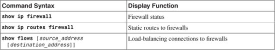
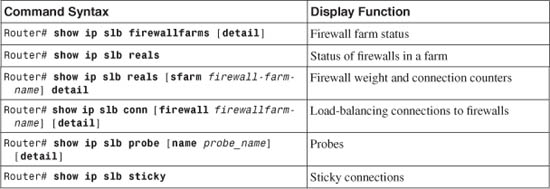
Table 9-2 lists the switch commands you can use to display helpful information about IOS firewall load-balancing configuration and status.
Table 9-2 Commands to Display IOS FWLB Configuration and Status
IOS FWLB Output Example
For the sample network shown in Figure 9-4, the outside firewall farm status is as follows:
Router# show ip slb firewallfarms name FW-INBOUND
firewall farm hash state reals
---------------------------------------------------
FW-INBOUND IPADDR INSERVICE 3
Router# show ip slb firewallfarms name FW-INBOUND detail
FW-INBOUND, hash = IPADDR, state = INSERVICE, reals = 3
FirewallTCP7:
sticky: <none>
idle = 3600, delay = 10, syns = 11, syn drop = 0
maxconns = 4294967295, conns = 11, total conns = 11
FirewallDG8:
sticky: <none>
idle = 3600
maxconns = 4294967295, conns = 0, total conns = 2653
Real firewalls:
192.168.100.3, weight = 8, OPERATIONAL, conns = 3
192.168.100.4, weight = 8, OPERATIONAL, conns = 5
192.168.100.5, weight = 8, OPERATIONAL, conns = 3
Total connections = 11
Here, the firewall farm FW-INBOUND has three “real” firewalls, each weighted equally using a hash algorithm based on IP addresses. Notice that after 11 connections (most from different source addresses to a single destination address), the connection load has been distributed rather equally across all the firewalls in the farm.
The sections of output beginning with FirewallTCP7 and FirewallDG8 show parameters set for the TCP and UDP protocols (DG stands for datagram).
To see a detailed history of each firewall’s activity within the firewall farm, enter the following command to get the resulting output:
Router# show ip slb reals sfarm FW-INBOUND
real farm name weight state conns
-------------------------------------------------------------------
192.168.100.3 FW-INBOUND 8 OPERATIONAL 4
192.168.100.4 FW-INBOUND 8 OPERATIONAL 6
192.168.100.5 FW-INBOUND 8 OPERATIONAL 5
Router# show ip slb reals sfarm FW-INBOUND detail
192.168.100.3, FW-INBOUND, state = OPERATIONAL, type = firewall
conns = 4, dummy_conns = 0, maxconns = 4294967295
weight = 8, weight(admin) = 8, metric = 0, remainder = 0
total conns established = 99036, hash count = 3
server failures = 0
interface Vlan100, MAC 000b.46b3.4e40
192.168.100.4, FW-INBOUND, state = OPERATIONAL, type = firewall
conns = 6, dummy_conns = 0, maxconns = 4294967295
weight = 8, weight(admin) = 8, metric = 0, remainder = 0
total conns established = 99383, hash count = 10
server failures = 0
interface Vlan100, MAC 000b.5f0c.8ac0
192.168.100.5, FW-INBOUND, state = OPERATIONAL, type = firewall
conns = 5, dummy_conns = 0, maxconns = 4294967295
weight = 8, weight(admin) = 8, metric = 0, remainder = 0
total conns established = 99532, hash count = 3
server failures = 0
interface Vlan100, MAC 0090.2744.5c66
To check on the progress of the firewall probes, you might enter the following command to get the resulting output:
Router# show ip slb probe
Server:Port Target:Port State Outages Current Cumulative
----------------------------------------------------------------------------------
192.168.100.3:0 192.168.100.3:0 OPERATIONAL 0 never 00:00:00
192.168.100.4:0 192.168.100.4:0 OPERATIONAL 0 never 00:00:00
192.168.100.5:0 192.168.100.5:0 OPERATIONAL 0 never 00:00:00
Router#
Router# show ip slb probe detail
FW-A, ping, address = 192.168.100.3, interval = 10, faildetect = 2
FW-INBOUND, type = firewall
target = 192.168.100.3:0, real = 192.168.100.3:0, virtual = 0.0.0.0:0 ALL
state = OPERATIONAL, status = 33, operation id = 25
outages = 0, failures = 374, successes = 98690, tests = 376
current = never, cumulative = 00:00:00
FW-B, ping, address = 192.168.100.4, interval = 10, faildetect = 2
FW-INBOUND, type = firewall
target = 192.168.100.4:0, real = 192.168.100.4:0, virtual = 0.0.0.0:0 ALL
state = OPERATIONAL, status = 33, operation id = 26
outages = 0, failures = 806, successes = 98604, tests = 808
current = never, cumulative = 00:00:00
FW-C, ping, address = 192.168.100.5, interval = 10, faildetect = 2
FW-INBOUND, type = firewall
target = 192.168.100.5:0, real = 192.168.100.5:0, virtual = 0.0.0.0:0 ALL
state = OPERATIONAL, status = 33, operation id = 27
outages = 0, failures = 995, successes = 98565, tests = 996
current = never, cumulative = 00:00:00
Router#
In the shaded portions, for example, probe FW-A sent to Firewall A (192.168.100.3) has succeeded 98,690 times and had 374 failures. The probe has been sent at 10-second intervals, causing the firewall to be declared in failure after two missed probes.
Sometimes, you might need to figure out which firewall in the farm is handling a specific flow or connection. For example, suppose a series of Telnet connections have been opened from a variety of client addresses, all to the same server. You can see the active connections with the output from the show ip slb conn command. Each active connection is listed, along with the “real” server or firewall that is handling that connection:
Router# show ip slb conn
vserver prot client real state nat
-------------------------------------------------------------------------------
FirewallTCP7 TCP 10.1.17.4:23 192.168.100.3 ESTAB none
FirewallTCP7 TCP 10.1.17.5:23 192.168.100.4 ESTAB none
FirewallTCP7 TCP 10.1.17.9:23 192.168.100.5 ESTAB none
FirewallTCP7 TCP 10.1.17.8:23 192.168.100.4 ESTAB none
FirewallTCP7 TCP 10.1.17.6:23 192.168.100.5 ESTAB none
FirewallTCP7 TCP 10.1.17.7:23 192.168.100.3 ESTAB none
FirewallTCP7 TCP 10.1.17.11:23 192.168.100.4 ESTAB none
FirewallTCP7 TCP 10.1.17.10:23 192.168.100.3 ESTAB none
FirewallTCP7 TCP 10.1.17.229:3580 192.168.100.4 ESTAB none
Router#
9-3 Firewall Load-Balancing in Hardware
FWLB is used to balance traffic flows to one or more firewall farms. A firewall farm is a group of firewalls that are connected in parallel or that have their inside (protected) and outside (unprotected) interfaces connected to common network segments.
FWLB requires a load-balancing device to be connected to each side of the firewall farm. A firewall farm with inside and outside interfaces would then require two load-balancing devices—each making sure that traffic flows are directed toward the same firewall for the duration of the connection.
FWLB can be performed in hardware with a CSM on the Catalyst 6500 switch platform. The CSM is a very robust and high-performance device, using the ASLB features to distribute connections to both server and firewall farms.
The CSM has no firewall farm concept. Rather, it treats a firewall farm as a regular server farm where the physical firewalls are configured as real servers in the farm. The CSM itself has logical interfaces that are configured as the gateway or next-hop addresses toward and away from a firewall farm.
To load-balance traffic, the CSM is configured with a virtual server that represents the firewall farm. As new traffic flows arrive at the virtual server, the CSM computes a hash value according to a predefined algorithm. This hash value determines which firewall is used within the firewall farm.
The CSM is flexible with how firewalls are connected and where they are located. Firewalls can reside on a single VLAN or subnet, or they can each reside on a unique subnet. As well, the firewalls can be more than one router hop away from the CSM.
The CSM can operate in the following modes, based on its placement between a firewall farm and the clients:
• Single subnet (bridge) mode—The clients and the firewall farm members all reside on one common IP subnet. However, each side of the CSM (client and server) must be assigned to unique VLANs that share the same IP subnet. The CSM distributes inbound connections to the firewalls by substituting the destination MAC address to match the next firewall to be used while bridging the packets from the client to the server VLAN.
This mode can be useful when you need to implement load-balancing needs in an existing network where it is not feasible to move the clients or the firewalls to different IP subnets. In other words, it is not possible to wedge a router between the clients and the firewalls. Instead, transparent or “stealth” Layer 2 firewalls are used in the firewall farm.
• Secure (router) mode—The clients and the firewall farm members are located on different IP subnets and VLANs. In this case, traditional Layer 3 or “routed mode” firewalls are used in the firewall farm.
The CSM distributes inbound connections to the firewalls by forwarding the packets just as a router would do. The CSM maintains an Address Resolution Protocol (ARP) cache of all the firewalls and substitutes the destination MAC address to point to the appropriate firewall.
Because the client and firewall farm IP subnets are different, the CSM must know enough routing information to distribute and forward connections to the firewalls. This becomes especially important when the firewalls are located more than one router hop away from the CSM.
CSM FWLB can detect a firewall failure by monitoring probe activity. One probe is configured and is used on all members of the firewall farm in succession. The CSM automatically inserts the target IP address of each firewall. The CSM also periodically gathers ARP data from each firewall and uses that information to detect firewall failures.
Multiple CSM FWLB devices can also use stateful backup for redundancy. Backup devices keep state information dynamically and can take over immediately if a failure occurs.
Note
The CSM is a standalone device installed in a Catalyst 6500 chassis. The CSM interfaces with the switch through a 6-Gbps channel that acts as a trunk carrying multiple VLANs. As soon as packets are handed off to the CSM, they are effectively isolated from the switch until the CSM sends them back.
As you might expect, FWLB can be performed by two separate CSMs, in either one or two physical switch chassis. However, the CSM architecture also allows FWLB using only a single CSM in one switch chassis. You can configure many separate virtual servers and firewall farms within one CSM so that all the FWLB devices needed to surround a firewall farm can be present in that CSM. This makes high-performance FWLB more cost-effective but limits the redundancy to a single CSM.
FWLB in Hardware Configuration Notes
FWLB is configured in two halves. One FWLB device must be placed on the outside of the firewall farm, and another is placed on the inside. Each FWLB device distributes connections toward the firewall. Therefore, the outside FWLB balances connections going into the firewall farm’s outside interfaces (inbound). The inside FWLB acts similarly for connections going into the firewall farm’s inside interfaces (outbound).
The CSM is configured differently from IOS FWLB because it supports only generic server farms that act as firewall farms. A virtual server and its server farm must be configured for each direction in which packets will be sent. Therefore, on each side of the firewall, you must configure the CSM with two virtual servers that either load-balance or just forward traffic in the inbound and outbound directions.
This might sound a bit complicated, but it really is not. Figure 9-5 shows how CSM FWLB devices use the various virtual servers. (For the purposes of this discussion, assume that two separate CSMs are being used.) On the outside of the firewall farm, that CSM needs one virtual server to distribute connections into a firewall farm’s outside interfaces in the inbound direction. A second “generic” virtual server takes care of the outbound traffic coming from the firewall farm. This virtual server is actually a simple traffic forwarder that makes no load-balancing decisions.
Figure 9-5 CSM FWLB Operation Surrounding a Firewall Farm
The inside CSM also has two virtual servers:
• One virtual server simply forwards inbound traffic toward the internal secure network.
• One virtual server is a true load balancer that distributes outbound connections to the firewalls’ inside interfaces.
Tip
If only one CSM can be used to provide FWLB around a firewall farm, how much network functionality can be put into a single Catalyst 6500 chassis? Plenty! That chassis can contain the usual Supervisor and line cards, along with the CSM, and up to four FWSMs. In other words, the outside public network and the inside secure network can exist on that switch as separate isolated VLANs, and the CSM provides robust load balancing to multiple high-performance firewall modules—all without compromising security.
The following sections present configuration steps for only one side (inside or outside) of the firewall farm. You need to repeat the sequence of steps for the FWLB functions on the other side of the firewall farm, too, assuming that you are working with firewalls that have dual (outside and inside) interfaces.
If you have more protected networks (DMZs, for example), you can apply the same concepts to the firewall farm’s other interfaces. Follow the steps listed for the inside FWLB configuration for any other interfaces needed, because these are all more secure interfaces than the outside.
Also notice that the configuration steps assume you are using two separate CSMs. These same steps easily apply to a single CSM scenario just by using all the commands (inside and outside FWLB) to configure that one CSM.
CSM FWLB Configuration
Because firewall load balancing with CSMs requires several different server farms and virtual servers, it is easy to forget what pieces need to be configured. Configure the inside and outside CSMs one at a time, and keep track of your progress in each by following the virtual servers and server farms that are shown in Figure 9-5. You need to repeat this configuration process for the inside and outside CSM.
1. Enter CSM server load-balancing mode:
Switch(config)# ip slb mode csm
A Catalyst 6500 switch can support SLB functionality on the route processor (RP) or Supervisor in the native IOS software. If a CSM is installed, you should use this command to convert the switch to using the CSM for all the SLB configuration commands.
After you issue this command, the switch needs to be reloaded, and all existing IOS SLB commands are automatically removed.
2. Select the CSM module:
Switch(config)# module csm slot-number
The native IOS CLI begins CSM configuration mode for the CSM located at slot-number in the switch chassis. To end this mode, use the exit command. To find the appropriate slot number, use the show module all command.
3. Define connectivity away from the firewall farm.
a. Identify the outside network VLAN:
Switch(config-module-csm)# vlan vlan-id client
The VLAN number is given as vlan-id (2 to 4095; VLAN 1 cannot be used). This VLAN must already be defined on the switch. Defining the VLAN as client means that the CSM expects new inbound connections to originate from clients there. These connections are distributed into a server-type VLAN where the firewall farm is located.
Tip
The CSM does not have a special configuration mode for firewall farms or FWLB. When configuring a CSM for FWLB, always consider the client-side VLAN of the CSM to be away from the firewalls. The server-side VLAN of the CSM is always closest or directly connected to the firewall farms.
b. Assign a primary IP address:
Switch(config-slb-vlan-client)# ip address ip-address netmask
One IP address can be defined per VLAN on the CSM. This address is used as the next-hop gateway for inbound traffic, as well as for management traffic (probes, for example) and ARP requests.
Tip
For the outside CSM, make sure the hosts or routers on the outside public (unsecure) network use this address as their next-hop gateway to reach the inside (secure) network. Likewise, for the inside CSM, make sure the inside (secure) hosts and routers use this address as their default gateway to the public network.
c. (Outside CSM only) Define a default gateway:
Switch(config-slb-vlan-client)# gateway ip-address
A next-hop default gateway or router address is given by ip-address. You can repeat this command to define up to 7 gateways per VLAN, or 255 gateways per CSM. Gateways are usually used on the client-side VLAN to forward outbound traffic to the next-hop router in the public network.
d. Exit client VLAN mode:
Switch(config-slb-vlan-client)# exit
4. Define connectivity toward the firewall farm.
a. Identify the nearest firewall farm VLAN:
Switch(config-module-csm)# vlan vlan-id server
This is the VLAN that is used to connect this CSM to the firewalls in the firewall farm. The VLAN number is given as vlan-id (2 to 4095; VLAN 1 cannot be used). This VLAN must already be defined on the switch. Defining the VLAN as server means that the CSM distributes new connections to firewall “servers” in the firewall farm.
Tip
The firewalls in a firewall farm can all be located on the same IP subnet and VLAN as the CSM. In this case, only one server VLAN needs to be defined on the CSM.
Having each firewall located on a separate IP subnet and VLAN is also valid. This can occur when the firewalls are located in different geographic locations or when they need to be logically isolated from each other. In this case, you need to create a server VLAN for each firewall in the farm. Each server VLAN is assigned an IP address that correlates to a specific firewall’s interface.
b. Assign a primary IP address:
Switch(config-slb-vlan-server)# ip address ip-address netmask
One IP address can be defined per VLAN on the CSM. For the outside CSM, this address is used as the next-hop gateway for outbound traffic from the firewalls. Likewise, for the inside CSM, this address is the next hop for inbound traffic from the firewalls. The CSM also uses this address as a source address when it generates management traffic (probes, for example) and ARP requests.
Tip
Make sure all the firewalls in the farm are configured with the outside CSM’s server-side VLAN IP address as their default gateway. The firewalls should also have the inside CSM’s server-side address as their next-hop gateway to reach the inside (secure) networks.
That way, the firewalls can easily forward packets to the appropriate CSM, which in turn forwards them to the public or secure network.
c. (Optional) Define additional IP addresses:
Switch(config-slb-vlan-server)# alias ip-address netmask
You can define an additional IP address and subnet on a server-side VLAN if necessary. This is similar to configuring a secondary IP address on a router interface. By repeating this command, you can add up to 255 additional addresses to a VLAN.
d. (Optional) Define static routes to reach distant networks:
Switch(config-slb-vlan-server)# route ip-address netmask gateway
gw-ip-address
You can define a static route when the CSM needs to know how to reach firewalls that are more than one router hop away. Define the route by the network ip-address and netmask using next-hop gateway address gw-ip-address. The gateway must reside on the same local network as the CSM server VLAN.
You do not need to use this command if each firewall is connected to the same IP subnet as a CSM server VLAN. In this case, no routing information is needed to reach the firewalls.
5. Define a probe for a firewall farm:
Switch(config-module-csm)# probe probe-name icmp
The probe is named probe-name (a text string of up to 15 characters) and can be referenced by other FWLB commands.
Tip
You do not have to configure a target IP address for a CSM probe. Rather, the CSM uses the probe definition and substitutes each firewall’s IP address from the firewall farm. Every firewall is automatically probed in this fashion.
Notice that this makes detecting complete firewall operation somewhat difficult. Ideally, you should send and receive ICMP packets that have passed all the way through a firewall to be sure it is completely functional. You normally use a target address of the far-side firewall interface or another device on the other side. This isn’t possible on the CSM; only the nearest firewall interface (the one configured in the firewall farm) is probed. At the least, if ICMP replies are received, you can safely assume that the firewall’s outside interface is up and running.
Tip
The CSM is somewhat unique with regard to probes. Even if no probes are defined and configured, it uses ARP requests that it regularly sends every 5 minutes to determine if each firewall in a farm is alive. If the firewall does not send an ARP reply, it is marked as failed. Although this is automatic, it is not very timely, because 5 minutes could pass before the CSM realizes there is a problem with a firewall. During that time, new connections could have been assigned to the dead firewall.
You should always define and use a probe for each firewall farm. Although you cannot configure the target IP addresses used by probes, you can tune the probe interval and the number of retries before a failure is declared.
a. (Optional) Set the amount of time between probes:
Switch(config-slb-probe-icmp)# interval seconds
Probes are sent toward the target at intervals of seconds (5 to 65535 seconds; the default is 120 seconds).
b. (Optional) Set how long to wait for a probe reply:
Switch(config-slb-probe-icmp)# receive receive-timeout
The CSM waits receive-timeout (1 to 65535 seconds; the default is 10 seconds) for an ICMP reply to be received before considering the probe failed.
c. (Optional) Define the criteria for a failure:
Switch(config-slb-probe-icmp)# retries retry-count
With a CSM, the target has failed if retry-count (0 to 65535; the default is 3) probes go unanswered.
d. (Optional) Wait to retry a failed firewall:
Switch(config-slb-probe-icmp)# failed failed-interval
After a CSM has determined that a firewall has failed, it waits failed-interval (5 to 65535 seconds; the default is 300 seconds) before sending another probe.
6. Define the firewall farm.
a. Assign a name to the firewall farm:
Switch(config-module-csm)# serverfarm serverfarm-name
The CSM views a firewall farm as just another form of a server farm, referenced by serverfarm-name (a text string of up to 15 characters).
b. Identify one or more firewalls in the farm:
Switch(config-slb-sfarm)# real ip-address
Switch(config-slb-real)# inservice
The firewall interface nearest to the CSM can be found at IP address ip-address. By default, the CSM does not use the firewall unless it is placed in service with the inservice command. To remove a firewall from service, use the no inservice command.
c. Choose a firewall load-balancing method:
Switch(config-slb-sfarm)# predictor hash address {source |
destination} 255.255.255.255
On a CSM located outside relative to the firewall farm (the unsecure side), the algorithm should use only the source addresses. On an inside CSM, the destination hash algorithm should be used. Here, you should set the netmask option to 255.255.255.255 so that all address bits are used in the hash algorithm.
In this fashion, inbound and outbound connections are distributed according to the largest and most diverse population of addresses—those found on the public network.
Tip
The CSM has a very robust load-balancing capability that can be based on source or destination addresses, a round-robin fashion, or the actual connection loads on each firewall. For firewall load balancing, the source and destination address hashes are the most useful and predictable.
You might be inclined to use one of the more dynamic hash algorithms so that the firewalls are loaded evenly. These algorithms include weighted round robin, which assigns a number of new connections to one firewall before moving on to the next one, and weighted least connections, which assigns new connections to the firewall that is least used at any given time. Or you might have a mix of firewall models in a firewall farm, where some have a higher throughput than others and should be used more.
In any event, the dynamic hash algorithms do not lend themselves to FWLB because multiple FWLB devices always surround a firewall farm. The outside FWLB device can do a nice, accurate job of evenly distributing the load to the outside of the firewall farm, but its information about the firewall loads, weighting, and number of active connections is not passed to the inside FWLB device. The same is true of the inside FWLB device. This makes it possible for some firewalls to be overloaded by a combination of inside and outside FWLB devices while others are underutilized.
d. Disable server NAT:
Switch(config-slb-sfarm)# no nat server
By default, server NAT is enabled for a CSM server farm (including a firewall farm). However, NAT is never needed when load-balancing to firewalls. The FWLB device should just pass IP addresses through unaltered.
e. Use one or more probes to detect failures within the firewall farm:
Switch(config-slb-sfarm)# probe probe-name
The probe that is defined by probe-name (a text string) is used to periodically check each firewall in the firewall farm. The probe inherits each firewall’s IP address from the list of real servers to use as a target address. You can define more than one probe, but a firewall is declared down if it fails just one probe. A firewall must pass all probes to be recovered again.
7. Define a virtual server to handle traffic toward the firewall farm.
a. Name the virtual server:
Switch(config-module-csm)# vserver virtual-server-name
The virtual server is given the name virtual-server-name (a text string of up to 15 characters).
b. Assign the virtual server to a firewall server farm:
Switch(config-slb-vserver)# serverfarm serverfarm-name
FWLB uses the virtual server as the front end for the server farm named serverfarm-name (a text string of up to 15 characters).
c. Define the virtual server’s IP address:
Switch(config-slb-vserver)# virtual ip-address [network-mask] any
The virtual server appears as IP address ip-address (the default is 0.0.0.0) with network-mask (the default is 255.255.255.255; 1 bits match, and 0 is a wildcard). In the default case (0.0.0.0 255.255.255.255), no destination addresses are ever matched, so no traffic is accepted.
In most cases, you can just define the virtual server to accept any destination (0.0.0.0 0.0.0.0), as long as you specify the ingress VLAN in Step 7d. The any keyword allows all protocols to be load-balanced.
However, it is good practice to be more specific by defining the virtual server to accept only the IP subnets that are behind the firewall farm on the inside (secure) network.
d. (Optional) Allow traffic only from a source VLAN to use the virtual server:
Switch(config-slb-vserver)# vlan vlan-number
By default, traffic from all VLANs is allowed to reach the firewalls through the virtual server. To restrict the access, specify a vlan-number (2 to 4095) that is to be allowed. This is usually the CSM VLAN that connects away from the firewalls. After it is defined, all other VLANs are restricted from accessing the virtual server.
e. Allow FWLB to begin using the virtual server:
Switch(config-slb-vserver)# inservice
By default, FWLB does not use the virtual server unless it is placed in service. To remove a virtual server from service, use the no inservice command.
f. (Optional) Use SLB stateful backup:
Switch(config-slb-vserver)# replicate csrp {sticky | connection}
CSM replicates its connection information using Content Switching Replication Protocol (CSRP). You can replicate the sticky connection database or the regular connection database. To replicate both, choose each one in a separate replicate csrp command.
8. Define a generic server farm for traffic away from the firewall farm.
a. Assign a name to the generic server farm:
Switch(config-module-csm)# serverfarm serverfarm-name
The CSM sees the network away from the firewall farm as a server farm. Here, the server farm represents the Internet or public network to the outside CSM and the internal (secure) network to the inside CSM.
Tip
You must also configure traffic away from the firewall farm for load balancing with a generic serverfarm having no real servers. Instead, a generic virtual server is used to forward all traffic through the generic server farm according to the CSM’s internal routing tables.
b. (Optional) Choose a load-balancing method:
Switch(config-slb-sfarm)# predictor forward
Here, the algorithm uses only forward mode without computing hash values. This merely forwards traffic destined away from the firewall farm according to the CSM’s internal routing table.
c. Disable server NAT:
Switch(config-slb-sfarm)# no nat server
By default, server NAT is enabled for a CSM server farm. In the case of firewall load balancing, NAT is not required, because packets should be presented to and from the firewalls unaltered.
9. Define a generic virtual server for traffic away from the firewall farm.
a. Name the virtual server:
Switch(config-module-csm)# vserver virtual-server-name
The virtual server is given the name virtual-server-name (a text string of up to 15 characters).
b. Assign the virtual server to the generic server farm:
Switch(config-slb-vserver)# serverfarm serverfarm-name
FWLB uses the virtual server as the front end for the generic server farm named serverfarm-name (a text string of up to 15 characters).
c. Let the virtual server accept all outbound traffic:
Switch(config-slb-vserver)# virtual 0.0.0.0 0.0.0.0 any
The virtual server matches any destination IP address so that traffic gets forwarded away from the firewall farm.
d. (Optional) Allow traffic only from a source VLAN to use the virtual server:
Switch(config-slb-vserver)# vlan vlan-number
By default, traffic from all VLANs is forwarded out through the virtual server. To restrict the access, specify a vlan-number (2 to 4095) that is to be allowed. This is usually the CSM VLAN that connects to the firewall farm. After it is defined, all other VLANs are restricted from accessing the virtual server.
e. (Optional) Use sticky connections to maintain client/server firewall mapping:
Switch(config-slb-vserver)# sticky duration [group group-id]
[netmask netmask] [source |destination | both]
Switch(config-slb-vserver)# reverse-sticky group-id
After a CSM builds a connection from a client to a real server (firewall) through a virtual server, it can make the connection “sticky” to permit subsequent client/server connections to use the same firewall. This is important for some applications, where one connection sets up the appropriate conditions for a second connection. This is commonly done with protocols such as H.323, where “buddy” ports or additional connections are negotiated and initiated.
You can enable sticky connections with the sticky command, where connections are held in the sticky database for duration (1 to 65535 minutes). By using the group keyword, you can organize the connections in the database as groups if certain types of connections should be held together. The group-id is 0 by default, but it can be 1 to 255.
Connections are flagged as “sticky” according to IP address criteria. You can provide a subnet mask designation with netmask netmask, where 1 bits signify the address bits that are eligible for stickiness. The actual address used can be source, destination, or both.
With firewall load balancing, sticky connections usually need to be extended further. This is because a CSM is configured with two virtual servers—one to load-balance connections toward the firewall farm and another to load-balance connections away from the firewall farm. In practice, these virtual servers work independently so that connections that are marked sticky through one virtual server do not appear sticky to the other virtual server.
To remedy this, you can enable reverse sticky connections with the reverse-sticky command. This is done on a per-group basis, where group-id (0 to 255) identifies the group created with the sticky command. As connections are load-balanced and made sticky in one direction, sticky entries are automatically made for them in the reverse direction. In effect, this provides a common sticky database for all the virtual servers.
f. Allow FWLB to begin using the virtual server:
Switch(config-slb-vserver)# inservice
By default, the virtual server is not used until it is placed in service. To remove a virtual server from service, use the no inservice command.
CSM Firewall Load-Balancing Example
The network from the example in Section 9-2 is reused here so that you can get a feel for the difference between IOS FWLB and CSM configurations.
To perform firewall load balancing, you need two load-balancing devices:
• One located externally with respect to the firewall farm
• One located internally with respect to the firewall farm
Figure 9-6 shows a network diagram for this example using CSMs as FWLB devices. Remember that in the case of CSMs, you have the flexibility to use two separate modules (in the same or different chassis) on each side of the firewall farm or a single CSM that simply connects to both sides of the firewall farm.
Figure 9-6 Network Diagram for the CSM FWLB Example

The firewall farm consists of three real firewalls.
The outside (unprotected) interfaces of the three firewalls are at 192.168.100.3, 192.168.100.4, and 192.168.100.5. On the outside, the default gateway to the public network is 192.168.1.1, and the external CSM FWLB device (Catalyst A) is at 192.168.1.2.
The inside (protected) interfaces of the three firewalls are at 192.168.200.3, 192.168.200.4, and 192.168.200.5. The internal CSM FWLB device performs firewall load balancing for outbound traffic to the firewall farm. On the internal secure network (192.168.199.0/24), one server is in use at 192.168.199.100. This server supports both inbound HTTP and Telnet connections.
Ping probes are used by both external and internal FWLB devices to test for firewall operation.
CSM Components Needed
Before we look at the actual configuration commands, you should understand the many logical pieces of the two CSMs that are used for FWLB. Remember that the CSM thinks of everything in terms of a server farm and its virtual server front end.
For the outside CSM, keep in mind that both inbound (toward the firewall farm and the inside secure network) and outbound (away from the firewall farm, toward the public network) connections exist. You need a server farm and virtual server pair in each of these directions. These are labeled as follows:
— FW-INBOUND—The server farm composed of individual firewalls (“real servers”) and their outside interfaces.
— V-INBOUND—The virtual server that distributes inbound connections among the firewall farm.
• Outbound connections:
— PUBLIC—A generic server farm that simply forwards all traffic toward the public network.
— V-OUTBOUND-100—The virtual server that accepts outbound connections from VLAN 100 (outside interfaces of the firewall farm).
The inside CSM is very similar, requiring the following inbound and outbound pairs of server farms and virtual servers:
• Inbound connections:
— INTERNAL—A generic server farm that simply forwards all traffic toward the internal (secure) network.
— V-INBOUND-200—The virtual server that accepts inbound connections from VLAN 200 (inside interfaces of the firewall farm).
• Outbound connections:
— FW-OUTBOUND—The server farm composed of individual firewalls (“real servers”) and their inside interfaces.
— V-OUTBOUND—The virtual server that distributes outbound connections among the firewall farm.
Basic Firewall Configuration
This section begins with the firewall configurations. Firewalls A and B are FWSMs installed in the Catalyst A chassis. Firewall C is an external Cisco ASA connected to Catalyst A through a Gigabit Ethernet link. These configuration commands are shown here to give you a basic idea of all the pieces that must be configured for FWLB. Notice that all three firewalls have identical security policies configured. This is important, because any of the three firewalls could be assigned connections from any pair of inside and outside hosts.
Firewall(config)# hostname fwsm-a
fwsm-a(config)# nameif vlan100 outside security0
fwsm-a(config)# nameif vlan200 inside security100
fwsm-a(config)# ip address outside 192.168.100.3 255.255.255.0
fwsm-a(config)# ip address inside 192.168.200.3 255.255.255.0
fwsm-a(config)# icmp permit 192.168.100.0 255.255.255.0 outside
fwsm-a(config)# icmp permit 192.168.200.0 255.255.255.0 inside
fwsm-a(config)# static (inside,outside) 192.168.199.0 192.168.199.0 netmask
255.255.255.0 0 0
fwsm-a(config)# object-group icmp-type ICMP
fwsm-a(config-icmp)# icmp-object echo
fwsm-a(config-icmp)# icmp-object echo-reply
fwsm-a(config-icmp)# icmp-object time-exceeded
fwsm-a(config-icmp)# icmp-object unreachable
fwsm-a(config-icmp)# exit
fwsm-a(config)# access-list acl_out permit tcp any host 192.168.199.100 eq telnet
fwsm-a(config)# access-list acl_out permit tcp any host 192.168.199.100 eq www
fwsm-a(config)# access-list acl_out permit icmp any host 192.168.199.100
object-group ICMP
fwsm-a(config)# access-list acl_in permit tcp 192.168.199.0 255.255.255.0 eq
telnet any
fwsm-a(config)# access-list acl_in permit tcp 192.168.199.0 255.255.255.0 eq www
any
fwsm-a(config)# access-list acl_in permit icmp 192.168.199.0 255.255.255.0 any
object-group ICMP
fwsm-a(config)# access-list acl_in permit icmp 192.168.200.0 255.255.255.0 any
object-group ICMP
fwsm-a(config)# access-group acl_out in interface outside
fwsm-a(config)# access-group acl_in in interface inside
fwsm-a(config)# route outside 0.0.0.0 0.0.0.0 192.168.100.1 1
fwsm-a(config)# route inside 192.168.199.0 255.255.255.0 192.168.200.1 1
___________________________________________________________________________
Firewall(config)# hostname fwsm-b
fwsm-b(config)# nameif vlan100 outside security0
fwsm-b(config)# nameif vlan200 inside security100
fwsm-b(config)# ip address outside 192.168.100.4 255.255.255.0
fwsm-b(config)# ip address inside 192.168.200.4 255.255.255.0
fwsm-b(config)# icmp permit 192.168.100.0 255.255.255.0 outside
fwsm-b(config)# icmp permit 192.168.200.0 255.255.255.0 inside
fwsm-b(config)# static (inside,outside) 192.168.199.0 192.168.199.0 netmask
255.255.255.0 0 0
fwsm-b(config)# object-group icmp-type ICMP
fwsm-b(config-icmp)# icmp-object echo
fwsm-b(config-icmp)# icmp-object echo-reply
fwsm-b(config-icmp)# icmp-object time-exceeded
fwsm-b(config-icmp)# icmp-object unreachable
fwsm-b(config-icmp)# exit
fwsm-b(config)# access-list acl_out permit tcp any host 192.168.199.100 eq telnet
fwsm-b(config)# access-list acl_out permit tcp any host 192.168.199.100 eq www
fwsm-b(config)# access-list acl_out permit icmp any host 192.168.199.100
object-group ICMP
fwsm-b(config)# access-list acl_in permit tcp 192.168.199.0 255.255.255.0 eq
telnet any
fwsm-b(config)# access-list acl_in permit tcp 192.168.199.0 255.255.255.0 eq www
any
fwsm-b(config)# access-list acl_in permit icmp 192.168.199.0 255.255.255.0 any
object-group ICMP
fwsm-b(config)# access-list acl_in permit icmp 192.168.200.0 255.255.255.0 any
object-group ICMP
fwsm-b(config)# access-group acl_out in interface outside
fwsm-b(config)# access-group acl_in in interface inside
fwsm-b(config)# route outside 0.0.0.0 0.0.0.0 192.168.100.1 1
fwsm-b(config)# route inside 192.168.199.0 255.255.255.0 192.168.200.1 1
______________________________________________________________
Firewall(config)# hostname asa-c
asa-c(config)# interface gb-ethernet0 1000full
asa-c(config)# interface gb-ethernet1 1000full
asa-c(config)# nameif gb-ethernet0 outside security0
asa-c(config)# nameif gb-ethernet1 inside security100
asa-c(config)# ip address outside 192.168.100.5 255.255.255.0
asa-c(config)# ip address inside 192.168.200.5 255.255.255.0
asa-c(config)# icmp permit 192.168.100.0 255.255.255.0 outside
asa-c(config)# icmp permit 192.168.200.0 255.255.255.0 inside
asa-c(config)# static (inside,outside) 192.168.199.0 192.168.199.0 netmask
255.255.255.0 0 0
asa-c(config)# object-group icmp-type ICMP
asa-c(config-icmp)# icmp-object echo
asa-c(config-icmp)# icmp-object echo-reply
asa-c(config-icmp)# icmp-object time-exceeded
asa-c(config-icmp)# icmp-object unreachable
asa-c(config-icmp)# exit
asa-c(config)# access-list acl_out permit tcp any host 192.168.199.100 eq telnet
asa-c(config)# access-list acl_out permit tcp any host 192.168.199.100 eq www
asa-c(config)# access-list acl_out permit icmp any host 192.168.199.100
object-group ICMP
asa-c(config)# access-list acl_in permit tcp 192.168.199.0 255.255.255.0 eq telnet
any
asa-c(config)# access-list acl_in permit tcp 192.168.199.0 255.255.255.0 eq www
any
asa-c(config)# access-list acl_in permit icmp 192.168.199.0 255.255.255.0 any
object-group ICMP
asa-c(config)# access-list acl_in permit icmp 192.168.200.0 255.255.255.0 any
object-group ICMP
asa-c(config)# access-group acl_out in interface outside
asa-c(config)# access-group acl_in in interface inside
asa-c(config)# route outside 0.0.0.0 0.0.0.0 192.168.100.1 1
asa-c(config)# route inside 192.168.199.0 255.255.255.0 192.168.200.1 1
Outside CSM FWLB Configuration
This section shows the configuration for the outside CSM. Notice that this is all done from the Catalyst 6500 CLI, because the commands pertaining to the CSM are automatically downloaded to it. This section begins with the preliminary commands to define VLANs and connectivity. Notice that the Catalyst switch handles routing only from the public network to the outside CSM. The outside and inside CSMs handle all other traffic forwarding from VLAN 10 on to the inside (secure) network. This effectively isolates the inside and outside networks, although they might be present in the same switch chassis.
Switch(config)# hostname CatalystA
! Define the VLANs
CatalystA(config)# vlan 10
CatalystA(config-vlan)# name Public-Network
CatalystA(config)# vlan 100
CatalystA(config-vlan)# name FW-outside
CatalystA(config)# vlan 200
CatalystA(config-vlan)# name FW-inside
CatalystA(config)# vlan 400
CatalystA(config-vlan)# name Internal-Network
! Pass the VLANs to the two FWSMs
CatalystA(config)# firewall module 3 vlan-group 1
CatalystA(config)# firewall module 4 vlan-group 1
CatalystA(config)# firewall vlan-group 1 100,200
! Set up the outside connection to PIX Firewall-C
CatalystA(config)# interface GigabitEthernet8/1
CatalystA(config-if)# description PIX-C outside
CatalystA(config-if)# no ip address
CatalystA(config-if)# switchport
CatalystA(config-if)# switchport access vlan 100
CatalystA(config-if)# switchport mode access
CatalystA(config-if)# spanning-tree portfast
! Define the Catalyst presence only on VLAN 10; CSM will handle everything beyond
! this
CatalystA(config-if)# interface Vlan10
CatalystA(config-if)# ip address 192.168.1.2 255.255.255.0
! Now define a way to get out to the public network
CatalystA(config)# ip default-gateway 192.168.1.1
CatalystA(config)# ip route 0.0.0.0 0.0.0.0 192.168.1.1
! For the internal (secure) network, define a route that points to the outside CSM
CatalystA(config)# ip route 192.168.199.0 255.255.255.0 192.168.1.1
Now, the actual outside CSM commands are addressed. The ip slb mode csm command should already be used to force the switch to perform all SLB functions on the CSM instead of using the route processor. (Remember that a CSM performs generic SLB; FWLB is possible by having SLB on each side of a firewall farm.)
! Configure the outside CSM on CatalystA
CatalystA(config)# module ContentSwitchingModule 7
CatalystA(config-module-csm)# vlan 10 client
CatalystA(config-slb-vlan-client)# ip address 192.168.1.3 255.255.255.0
CatalystA(config-slb-vlan-client)# gateway 192.168.1.2
CatalystA(config-slb-vlan-client)# exit
!
CatalystA(config-module-csm)# vlan 100 server
CatalystA(config-slb-vlan-server)# ip address 192.168.100.1 255.255.255.0
CatalystA(config-slb-vlan-server)# exit
!
! Define a probe to detect failures within the firewall farm
CatalystA(config-module-csm)# probe FARM-PROBE-OUTSIDE icmp
CatalystA(config-slb-probe-icmp)# interval 15
CatalystA(config-slb-probe-icmp)# exit
!
! Define the inbound firewall farm
CatalystA(config-module-csm)# serverfarm FW-INBOUND
CatalystA(config-slb-sfarm)# no nat server
CatalystA(config-slb-sfarm)# no nat client
CatalystA(config-slb-sfarm)# probe FARM-PROBE-OUTSIDE
CatalystA(config-slb-sfarm)# predictor hash address source
CatalystA(config-slb-sfarm)# real 192.168.100.3
CatalystA(config-slb-real)# inservice
CatalystA(config-slb-real)# exit
CatalystA(config-slb-sfarm)# real 192.168.100.4
CatalystA(config-slb-real)# inservice
CatalystA(config-slb-real)# exit
CatalystA(config-slb-sfarm)# real 192.168.100.5
CatalystA(config-slb-real)# inservice
CatalystA(config-slb-real)# exit
!
! Define the front end of the inbound FW farm
CatalystA(config-module-csm)# vserver V-INBOUND
CatalystA(config-slb-vserver)# virtual 0.0.0.0 0.0.0.0 any
CatalystA(config-slb-vserver)# vlan 10
CatalystA(config-slb-vserver)# serverfarm FW-INBOUND
CatalystA(config-slb-vserver)# inservice
CatalystA(config-slb-vserver)# exit
!
! Define the outbound forwarder
CatalystA(config-module-csm)# serverfarm PUBLIC
CatalystA(config-slb-sfarm)# no nat server
CatalystA(config-slb-sfarm)# no nat client
CatalystA(config-slb-sfarm)# predictor forward
CatalystA(config-slb-sfarm)# exit
!
! Define the front end to the outbound forwarder
CatalystA(config-module-csm)# vserver V-PUBLIC-100
CatalystA(config-slb-vserver)# virtual 0.0.0.0 0.0.0.0 any
CatalystA(config-slb-vserver)# vlan 100
CatalystA(config-slb-vserver)# serverfarm PUBLIC
CatalystA(config-slb-vserver)# inservice
!
Inside CSM Configuration
This section covers the configuration for the inside CSM. At this point, you should notice that you are still configuring things on Catalyst A. Only one physical CSM acts as both outside and inside FWLB devices.
First, here are the commands to define VLANs and connectivity:
! Set up the inside connection to ASA Firewall-C
CatalystA(config)# interface GigabitEthernet8/2
CatalystA(config-if)# description PIX-C inside
CatalystA(config-if)# no ip address
CatalystA(config-if)# switchport
CatalystA(config-if)# switchport access vlan 200
CatalystA(config-if)# switchport mode access
CatalystA(config-if)# spanning-tree portfast
! Set up the inside connection the example server 192.168.199.100
CatalystA(config)# interface GigabitEthernet8/3
CatalystA(config-if)# description Inside Server
CatalystA(config-if)# no ip address
CatalystA(config-if)# switchport
CatalystA(config-if)# switchport access vlan 400
CatalystA(config-if)# switchport mode access
CatalystA(config-if)# spanning-tree portfast
Next are the actual inside CSM commands:
! Configure the inside CSM (also on CatalystA)
CatalystA(config)# module ContentSwitchingModule 7
CatalystA(config-module-csm)# vlan 400 client
CatalystA(config-slb-vlan-client)# ip address 192.168.199.1 255.255.255.0
CatalystA(config-slb-vlan-client)# exit
!
CatalystA(config-module-csm)# vlan 200 server
CatalystA(config-slb-vlan-server)# ip address 192.168.200.1 255.255.255.0
CatalystA(config-slb-vlan-server)# exit
!
! Define a probe to detect failures within the firewall farm
CatalystA(config-module-csm)# probe FARM-PROBE-INSIDE icmp
CatalystA(config-slb-probe-icmp)# interval 15
!
! Define the outbound firewall farm
CatalystA(config-module-csm)# serverfarm FW-OUTBOUND
CatalystA(config-slb-sfarm)# no nat server
CatalystA(config-slb-sfarm)# no nat client
CatalystA(config-slb-sfarm)# probe FARM-PROBE-INSIDE
CatalystA(config-slb-sfarm)# predictor hash address destination
CatalystA(config-slb-sfarm)# real 192.168.200.3
CatalystA(config-slb-real)# inservice
CatalystA(config-slb-real)# exit
CatalystA(config-slb-sfarm)# real 192.168.200.4
CatalystA(config-slb-real)# inservice
CatalystA(config-slb-real)# exit
CatalystA(config-slb-sfarm)# real 192.168.200.5
CatalystA(config-slb-real)# inservice
CatalystA(config-slb-real)# exit
!
! Define the front end of the outbound FW farm
CatalystA(config-module-csm)# vserver V-OUTBOUND
CatalystA(config-slb-vserver)# virtual 0.0.0.0 0.0.0.0 any
CatalystA(config-slb-vserver)# vlan 400
CatalystA(config-slb-vserver)# serverfarm FW-OUTBOUND
CatalystA(config-slb-vserver)# inservice
CatalystA(config-slb-vserver)# exit
!
! Define the inbound forwarder
CatalystA(config-module-csm)# serverfarm INTERNAL
CatalystA(config-slb-sfarm)# no nat server
CatalystA(config-slb-sfarm)# no nat client
CatalystA(config-slb-sfarm)# predictor forward
CatalystA(config-slb-sfarm)# exit
!
! Define the front end to the inbound forwarder
CatalystA(config-module-csm)# vserver V-INBOUND-200
CatalystA(config-slb-vserver)# virtual 192.168.199.100 255.255.255.255 any
CatalystA(config-slb-vserver)# vlan 200
CatalystA(config-slb-vserver)# serverfarm INTERNAL
CatalystA(config-slb-vserver)# inservice
!
Displaying Information About CSM FWLB
You can use the switch commands listed in Table 9-3 to display helpful information about a CSM FWLB configuration and its status.
Table 9-3 Commands to Display CSM FWLB Configuration and Status
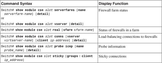
CSM FWLB Output Example
For the network shown in Figure 9-6, you can display the status of the inside (outbound) firewall farm as follows:
Switch# show module csm 7 reals
real server farm weight state conns/hits
-------------------------------------------------------------------------
192.168.200.3 FW-OUTBOUND 8 OPERATIONAL 0
192.168.200.4 FW-OUTBOUND 8 OPERATIONAL 0
192.168.200.5 FW-OUTBOUND 8 FAILED 0
Switch#
Notice that two of the three firewalls are working, but the third is in a FAILED state. It has not answered probes or ARP requests from the CSM.
Now, suppose the third firewall is restored to service. You can use the same command to watch the connection load that has been distributed to each firewall. Remember that the number of connections shown represents only the new connections that have originated on one side of the firewall farm. The return traffic for those connections is always forwarded back through the same firewalls, so it is not recorded as additional connections.
For example, the show module csm mod reals command has been issued after each new outbound connection. Here, the destination IP addresses have been incremented just to show how the connections build and are distributed among the firewalls in the farm:
Switch# show module csm 7 reals
real server farm weight state conns/hits
-------------------------------------------------------------------------
192.168.200.3 FW-OUTBOUND 8 OPERATIONAL 0
192.168.200.4 FW-OUTBOUND 8 OPERATIONAL 0
192.168.200.5 FW-OUTBOUND 8 OPERATIONAL 0
Switch# show module csm 7 reals
real server farm weight state conns/hits
-------------------------------------------------------------------------
192.168.200.3 FW-OUTBOUND 8 OPERATIONAL 1
192.168.200.4 FW-OUTBOUND 8 OPERATIONAL 0
192.168.200.5 FW-OUTBOUND 8 OPERATIONAL 0
Switch# show module csm 7 reals
real server farm weight state conns/hits
-------------------------------------------------------------------------
192.168.200.3 FW-OUTBOUND 8 OPERATIONAL 1
192.168.200.4 FW-OUTBOUND 8 OPERATIONAL 1
192.168.200.5 FW-OUTBOUND 8 OPERATIONAL 0
Switch# show module csm 7 reals
real server farm weight state conns/hits
-------------------------------------------------------------------------
192.168.200.3 FW-OUTBOUND 8 OPERATIONAL 1
192.168.200.4 FW-OUTBOUND 8 OPERATIONAL 1
192.168.200.5 FW-OUTBOUND 8 OPERATIONAL 1
Switch# show module csm 7 reals
real server farm weight state conns/hits
-------------------------------------------------------------------------
192.168.200.3 FW-OUTBOUND 8 OPERATIONAL 2
192.168.200.4 FW-OUTBOUND 8 OPERATIONAL 1
192.168.200.5 FW-OUTBOUND 8 OPERATIONAL 1
As long as the destination addresses are increasing by 1, the connections are distributed in a round-robin fashion. In actual use, the source and destination addresses can vary greatly, causing the hash algorithm to distribute the connections in an unpredictable fashion. The idea is that there should be a large distribution of address values, causing the connections to be distributed more or less equally among the firewalls.
The CSM must also build an ARP cache so that it can communicate with other devices. To display the MAC and IP address associations it has built, you can use the show module csm mod arp command:
Switch# show module csm 7 arp
Internet Address Physical Interface VLAN Type Status
--------------------------------------------------------------------
192.168.199.1 00-02-FC-E0-7E-B2 400 --SLB-- local
192.168.200.1 00-02-FC-E0-7E-B2 200 --SLB-- local
192.168.200.3 00-0B-46-B3-4E-40 200 REAL up(0 misses)
192.168.200.4 00-0B-5F-0C-8A-C0 200 REAL up(0 misses)
192.168.200.5 00-90-27-6C-3D-0A 200 REAL up(0 misses)
192.168.199.100 00-50-E2-C6-F6-80 400 LEARNED up(0 misses)
Switch#
The --SLB-- entries are the CSM VLAN interfaces, the REAL entries are the configured firewall addresses, and the LEARNED entries have been learned from traffic on a VLAN.
To see a quick summary of how the CSM probes have been configured, use the show module csm mod probe icmp command:
Switch# show module csm 7 probe icmp
probe type interval retries failed open receive
---------------------------------------------------------------------
FARM-PROBE-INSIDE icmp 10 2 300 10
Switch#
Here, the probe is using ICMP at 10-second intervals. The probe waits 10 seconds to receive a reply and declares the firewall failed after two probes go unanswered. Finally, as soon as a firewall is in the failed state, the CSM waits 300 seconds before trying to probe again.
You might also be interested in monitoring the connections that are load-balanced by a CSM. The show module csm mod conns command displays a list of the active connections:
Switch# show module csm 7 conns
prot vlan source destination state
----------------------------------------------------------------------
In TCP 400 192.168.199.100:13825 10.1.17.9:23 ESTAB
Out TCP 200 10.1.17.9:23 192.168.199.100:13825 ESTAB
In TCP 400 192.168.199.100:13313 10.1.17.8:23 ESTAB
Out TCP 200 10.1.17.8:23 192.168.199.100:13313 ESTAB
In TCP 400 192.168.199.100:12801 10.1.17.7:23 ESTAB
Out TCP 200 10.1.17.7:23 192.168.199.100:12801 ESTAB
In TCP 400 192.168.199.100:11265 10.1.17.4:23 ESTAB
Out TCP 200 10.1.17.4:23 192.168.199.100:11265 ESTAB
Each is shown with the In and Out VLANs, so you can see the connection traffic in both directions. Notice that the CSM does not have a way to display a connection and the firewall that has been assigned to handle it.
9-4 Firewall Load-Balancing Appliance
A Cisco CSS acts as a multilayer switch and performs FWLB as well as many other types of content processing. A CSS interface can carry a single VLAN or a trunk with multiple VLANs.
A CSS unit must be placed on each side of a firewall farm so that connections are load-balanced to the firewalls in each direction. Firewalls are defined individually rather than as a distinct firewall farm.
The CSS performs a route lookup on each inbound connection to determine the possible firewalls that can be used. The CSS then computes the exclusive OR (XOR) of the source and destination IP addresses as a hash value to select which firewall will receive the connection.
Keepalives (custom ICMP packets) are sent from one CSS to the other at regular intervals. If keepalives are not received from the opposite CSS through a firewall, that firewall is declared dead (failed).
CSS FWLB Configuration
You can use the following steps to configure FWLB on one CSS device. Remember that FWLB requires a load-balancing device on each side of the firewall farm. Be sure to repeat the entire configuration process for the outside and inside CSS FWLB platforms.
1. Configure each CSS physical interface.
a. Select the interface:
(config) interface interface_name
b. Configure trunking mode (one or multiple VLANs):
(config-if) bridge vlan vlan-id
or
(config-if) trunk
To carry only one VLAN on the interface, use the bridge vlan vlan-id command. The interface is assigned to VLAN number vlan-id (1 to 4094; the default is 1). The CSS performs Layer 2 bridging between interfaces with the same VLAN assignments.
To carry multiple VLANs on the interface, you can configure it as an 802.1Q trunk. Use the trunk command.
c. (Optional; trunk only) Identify each VLAN to be trunked:
(config-if) vlan vlan-id
VLAN number vlan-id (1 to 4094) is encapsulated on the trunk link. To identify the VLAN as the native VLAN (unencapsulated or untagged frames), follow this with the default-vlan command.
2. Assign IP addresses to the CSS VLANs.
a. Define a logical circuit:
(config) circuit circuit_name
Here, the circuit represents a logical interface within the CSS. You can see a list of available circuit names with the circuit ? command. Generally, circuit_name is a VLAN that has been configured in the CSS, of the form VLAN vlan-id.
b. Assign an IP address:
(config-circuit) ip address ip_address subnet_mask
(config-circuit-ip) enable
3. (Optional) Define a default route toward the public network:
(config) ip route 0.0.0.0 0.0.0.0 next-hop-address
On the outside CSS unit, you should configure a default route so that traffic can be forwarded to and from the public network. The next-hop-address is the IP address of the nearest router in the public network.
4. Define each firewall in the firewall farm:
(config) ip firewall index local_firewall_address remote_firewall_address
remote_css_address
You must assign each firewall in the farm a unique arbitrary index number (1 to 254). The firewall must have the same index configured in both inside and outside CSS units.
You must also define the firewall in terms of its IP addresses. The local_firewall_address is the address of the interface nearest to the CSS, and the remote_firewall_address is the address nearest to the CSS on the other side of the firewall. The other CSS unit must also be defined by its IP address remote_css_address. (The remote-side IP addresses are defined here because of how the CSS detects firewall failures.)
4. Define static routes to reach beyond the firewall farm:
(config) ip route ip_address subnet_mask firewall index distance
The CSS on one side of the firewall farm needs to know about any networks that are located on the other side. You can define a static route to the network ip_address with a subnet mask subnet_mask (either in dotted-decimal or /n prefix length notation). This route can be reached through the firewall with an index number index (1 to 254).
You can also assign an administrative distance to the route to adjust whether static or dynamic routes are more preferable. You can also use the distance (1 to 254; the default is 1; lower is more preferable) to differentiate between two or more sets of firewalls.
For example, if you normally expect traffic to pass through one firewall farm (indices 1 through n), you could use a distance of 1. Then define other static routes to the same destination network, but point to a different firewall and use a higher distance. The route (and firewalls) with the lower distance is used unless all of them have failed.
5. (Optional) Adjust the keepalive timing:
(config) ip firewall timeout seconds
Each CSS unit expects to receive keepalive probes at regular intervals from the CSS on the other side of the firewall farm. The keepalive probes are sent every seconds (3 to 16; the default is 3 seconds) and are expected to be received every seconds.
Tip
You must configure the keepalive timeout interval identically for the CSS units on both sides of the firewall farm. With identical configurations, both units correctly detect a failed keepalive from each other at the same time. At that time, each unit declares its side of the firewall to be dead, and subsequent connections are assigned to another firewall. Otherwise, if both units do not detect the same failure, connections could be improperly assigned to the firewalls in an asymmetric fashion.
Tip
Each CSS sends an ICMP packet as a keepalive to the target address of the opposing CSS unit. Each CSS also substitutes the destination MAC address of the specific firewall that is being tested so that the keepalive probe passes through that firewall.
For this reason, you must make sure that each firewall in the firewall farm is configured to pass ICMP packets between the two CSS IP addresses. The ICMP packets (both echo and echo-reply) must be able to pass through the firewall in both directions (outside to inside and inside to outside).
CSS Appliance Firewall Load-Balancing Example
The network from the example in Section 9-2 is reused here so that you can get a feel for the difference between IOS FWLB, CSM FWLB, and CSS FWLB configurations.
Performing FWLB using this method requires two CSS load-balancing devices:
• One located externally with respect to the firewall farm
• One located internally with respect to the firewall farm
Figure 9-7 shows a network diagram for this example.
Figure 9-7 Network Diagram for the CSS FWLB Example
The firewall farm consists of three real firewalls.
The outside (unprotected) interfaces of the three real firewalls are at 192.168.100.3, 192.168.100.4, and 192.168.100.5. On the outside, the default gateway to the public network is 192.168.1.1, and the outside CSS unit is at 192.168.1.2.
The inside (protected) interfaces of the three real firewalls are at 192.168.200.3, 192.168.200.4, and 192.168.200.5. The inside CSS unit performs firewall load balancing for outbound traffic to the firewall farm. On the internal secure network (192.168.199.0/24), one server is in use at 192.168.199.100. This server supports both inbound HTTP and Telnet connections.
Basic Firewall Configuration
This section begins with coverage of the firewall configurations. Firewalls A and B are FWSMs installed in the Catalyst A chassis. Firewall C is an external Cisco PIX Firewall, connected to Catalyst A through a Gigabit Ethernet link. This section shows the configuration commands to give you a basic idea of all the pieces that must be configured for FWLB using an FWLB appliance. Notice that all three firewalls have identical security policies configured. This is important because any of the three firewalls could be assigned connections from any pair of inside and outside hosts.
Notice also that access list rules have been configured to allow the inside and outside CSS units to pass ICMP packets between each other. This is important to allow each CSS to monitor the health of each firewall:
Firewall(config)# hostname fwsm-a
fwsm-a(config)# nameif vlan100 outside security0
fwsm-a(config)# nameif vlan200 inside security100
fwsm-a(config)# ip address outside 192.168.100.3 255.255.255.0
fwsm-a(config)# ip address inside 192.168.200.3 255.255.255.0
fwsm-a(config)# icmp permit 192.168.100.0 255.255.255.0 outside
fwsm-a(config)# icmp permit 192.168.200.0 255.255.255.0 inside
fwsm-a(config)# static (inside,outside) 192.168.199.100 192.168.199.100 netmask
255.255.255.255 0 0
fwsm-a(config)# static (inside,outside) 192.168.200.1 192.168.200.1 netmask
255.255.255.255 0 0
fwsm-a(config)# static (inside,outside) 192.168.100.1 192.168.100.1 netmask
255.255.255.255 0 0
fwsm-a(config)# object-group icmp-type ICMP
fwsm-a(config-icmp)# icmp-object echo
fwsm-a(config-icmp)# icmp-object echo-reply
fwsm-a(config-icmp)# icmp-object time-exceeded
fwsm-a(config-icmp)# icmp-object unreachable
fwsm-a(config-icmp)# exit
fwsm-a(config)# access-list acl_out permit icmp host 192.168.100.1 host
192.168.200.1
fwsm-a(config)# access-list acl_out permit tcp any host 192.168.199.100 eq telnet
fwsm-a(config)# access-list acl_out permit tcp any host 192.168.199.100 eq www
fwsm-a(config)# access-list acl_out permit icmp any host 192.168.199.100
object-group ICMP
fwsm-a(config)# access-list acl_in permit ip 192.168.199.100 255.255.255.255 any
fwsm-a(config)# access-list acl_in permit icmp host 192.168.200.1 host
192.168.100.1
fwsm-a(config)# access-group acl_out in interface outside
fwsm-a(config)# access-group acl_in in interface inside
fwsm-a(config)# route outside 0.0.0.0 0.0.0.0 192.168.100.1 1
fwsm-a(config)# route inside 192.168.199.0 255.255.255.0 192.168.200.1 1
___________________________________________________________________________
Firewall(config)# hostname fwsm-b
fwsm-b(config)# nameif vlan100 outside security0
fwsm-b(config)# nameif vlan200 inside security100
fwsm-b(config)# ip address outside 192.168.100.4 255.255.255.0
fwsm-b(config)# ip address inside 192.168.200.4 255.255.255.0
fwsm-b(config)# icmp permit 192.168.100.0 255.255.255.0 outside
fwsm-b(config)# icmp permit 192.168.200.0 255.255.255.0 inside
fwsm-b(config)# static (inside,outside) 192.168.199.100 192.168.199.100 netmask
255.255.255.0 0 0
fwsm-b(config)# static (inside,outside) 192.168.200.1 192.168.200.1 netmask
255.255.255.255 0 0
fwsm-b(config)# static (inside,outside) 192.168.100.1 192.168.100.1 netmask
255.255.255.255 0 0
object-group icmp-type ICMP
fwsm-a(config-icmp)# icmp-object echo
fwsm-a(config-icmp)# icmp-object echo-reply
fwsm-a(config-icmp)# icmp-object time-exceeded
fwsm-a(config-icmp)# icmp-object unreachable
fwsm-a(config-icmp)# exit
fwsm-b(config)# access-list acl_out permit icmp host 192.168.100.1 host
192.168.200.1
fwsm-b(config)# access-list acl_out permit tcp any host 192.168.199.100 eq telnet
fwsm-b(config)# access-list acl_out permit tcp any host 192.168.199.100 eq www
fwsm-b(config)# access-list acl_out permit icmp any host 192.168.199.100
object-group ICMP
fwsm-b(config)# access-list acl_in permit ip 192.168.199.100 255.255.255.255 any
fwsm-b(config)# access-list acl_in permit icmp host 192.168.200.1 host
192.168.100.1
fwsm-b(config)# access-group acl_out in interface outside
fwsm-b(config)# access-group acl_in in interface inside
fwsm-b(config)# route outside 0.0.0.0 0.0.0.0 192.168.100.1 1
fwsm-b(config)# route inside 192.168.199.0 255.255.255.0 192.168.200.1 1
___________________________________________________________________________
Firewall(config)# hostname asa-c
asa-c(config)# interface gb-ethernet0 1000full
asa-c(config)# interface gb-ethernet1 1000full
asa-c(config)# nameif gb-ethernet0 outside security0
asa-c(config)# nameif gb-ethernet1 inside security100
asa-c(config)# ip address outside 192.168.100.5 255.255.255.0
asa-c(config)# ip address inside 192.168.200.5 255.255.255.0
asa-c(config)# icmp permit 192.168.100.0 255.255.255.0 outside
asa-c(config)# icmp permit 192.168.200.0 255.255.255.0 inside
asa-c(config)# static (inside,outside) 192.168.199.100 192.168.199.100 netmask
255.255.255.0 0 0
asa-c(config)# static (inside,outside) 192.168.200.1 192.168.200.1 netmask
255.255.255.255 0 0
asa-c(config)# static (inside,outside) 192.168.100.1 192.168.100.1 netmask
255.255.255.255 0 0
asa-c(config)# object-group icmp-type ICMP
asa-c(config-icmp)# icmp-object echo
asa-c(config-icmp)# icmp-object echo-reply
asa-c(config-icmp)# icmp-object time-exceeded
asa-c(config-icmp)# icmp-object unreachable
asa-c(config-icmp)# exit
asa-c(config)# access-list acl_out permit icmp host 192.168.100.1 host
192.168.200.1
asa-c(config)# access-list acl_out permit tcp any host 192.168.199.100 eq telnet
asa-c(config)# access-list acl_out permit tcp any host 192.168.199.100 eq www
asa-c(config)# access-list acl_out permit icmp any host 192.168.199.100
object-group ICMP
asa-c(config)# access-list acl_in permit ip 192.168.199.100 255.255.255.255 any
asa-c(config)# access-list acl_in permit icmp host 192.168.200.1 host
192.168.100.1
asa-c(config)# access-group acl_out in interface outside
asa-c(config)# access-group acl_in in interface inside
asa-c(config)# route outside 0.0.0.0 0.0.0.0 192.168.100.1 1
asa-c(config)# route inside 192.168.199.0 255.255.255.0 192.168.200.1 1
Outside CSS FWLB Configuration
The outside CSS unit is configured with three firewalls and three static routes. Notice that each of the static routes lists the internal (secure) network as the destination and has each firewall as a next-hop gateway address. Firewall keepalive probes are sent and are expected every 3 seconds by default. The configuration commands are as follows:
(config) interface ethernet-1
(config-if) description "Outside public network"
(config-if) bridge vlan 10
(config) circuit VLAN10
(config-circuit) description "Circuit to the outside network"
(config-circuit) ip address 192.168.1.2 255.255.255.0
(config-circuit-ip) enable
(config) interface ethernet-2
(config-if) description "Firewall farm outside"
(config-if) bridge vlan 100
(config) circuit VLAN100
(config-circuit) description "Circuit to the firewall farm"
(config-circuit) ip address 192.168.100.1 255.255.255.0
(config-circuit-ip) enable
(config) ip route 0.0.0.0 0.0.0.0 192.168.1.1
(config) ip firewall 1 192.168.100.3 192.168.200.3 192.168.200.1
(config) ip firewall 2 192.168.100.4 192.168.200.4 192.168.200.1
(config) ip firewall 3 192.168.100.5 192.168.200.5 192.168.200.1
(config) ip route 192.168.199.0 255.255.255.0 firewall 1 1
(config) ip route 192.168.199.0 255.255.255.0 firewall 2 1
(config) ip route 192.168.199.0 255.255.255.0 firewall 3 1
(config) ip route 192.168.200.0 255.255.255.0 firewall 1 1
(config) ip route 192.168.200.0 255.255.255.0 firewall 2 1
(config) ip route 192.168.200.0 255.255.255.0 firewall 3 1
Inside CSS FWLB Configuration
The inside CSS unit is also configured with the inside addresses of the three firewalls. Notice this time that three static routes have been configured as default routes to reach the outside public network. Each one has a different firewall as a next-hop gateway address. Firewall keepalive probes are sent and are expected every 3 seconds by default. The configuration commands are as follows:
(config) interface ethernet-1
(config-if) description "Firewall farm inside"
(config-if) bridge vlan 200
(config) circuit VLAN200
(config-circuit) description "Circuit to the firewall farm"
(config-circuit) ip address 192.168.200.1 255.255.255.0
(config-circuit-ip) enable
(config) interface ethernet-2
(config-if) description "Inside private network"
(config-if) bridge vlan 400
(config) circuit VLAN400
(config-circuit) description "Circuit to the inside network"
(config-circuit) ip address 192.168.199.1 255.255.255.0
(config-circuit-ip) enable
(config) ip firewall 1 192.168.200.3 192.168.100.3 192.168.100.1
(config) ip firewall 2 192.168.200.4 192.168.100.4 192.168.100.1
(config) ip firewall 3 192.168.200.5 192.168.100.5 192.168.100.1
(config) ip route 0.0.0.0 0.0.0.0 firewall 1 1
(config) ip route 0.0.0.0 0.0.0.0 firewall 2 1
(config) ip route 0.0.0.0 0.0.0.0 firewall 3 1
Displaying Information About CSS FWLB
Table 9-4 lists the CSS commands that you can use to display helpful information about CSS FWLB configuration and status.
Table 9-4 Commands to Display CSS FWLB Configuration and Status