
Chapter 8. Increasing Firewall Availability with Failover
Refer to the following sections for information about these topics:
• 8-1: Firewall Failover Overview—Provides a concise reference of information about how Cisco firewall failover works.
• 8-2: Configuring Firewall Failover—Covers the steps needed to configure and use firewalls as a failover pair.
• 8-3: Firewall Failover Configuration Examples—Presents several complete examples of different types of failover configurations.
• 8-4: Managing Firewall Failover—Explains the commands you can use to verify failover operation and to manually intervene in the failover process.
• 8-5: Upgrading Firewalls in Failover Mode—Discusses a strategy for upgrading the operating system image on a failover pair of firewalls.
The previous chapters in this book explain how to configure a single Cisco firewall to inspect traffic and provide the necessary security policies in a network. As long as that firewall continues to run properly, has a continuous source of power, and has consistent network connectivity, it can offer reliable service. What happens when those conditions are less than perfect?
Cisco firewalls can be configured as failover pairs, allowing two physical firewall platforms to operate in tandem. The result is greater reliability, because one or both firewalls are always available for use. Firewall failover is possible in two forms:
• Active-standby—One firewall takes on the active role, handling all the normal security functions. The other firewall stays in standby mode, ready to take over the active role in the event of a failure.
• Active-active—Both firewalls can operate with one or more separate security contexts. For each context, one firewall can take on the active role, handling all the normal firewall functions for that context. The other firewall can take on the standby role for the context, waiting to take over the active role from its peer.
The active and standby roles can be arbitrarily assigned across the whole set of security contexts. In this way, one firewall is active for one group of contexts, and the other firewall is active for another group.
8-1 Firewall Failover Overview
When a single firewall is used in a network, the security it provides generally has the following attributes:
• Lower cost—Only one hardware platform and a software license are needed.
• Single point of failure—If the firewall hardware or software fails, no traffic can be forwarded from one side to the other.
• Performance is limited—The total throughput of the stateful inspection process is limited to the firewall’s maximum performance.
If one firewall is potentially a single point of failure, it is logical to think that two firewalls would be better. Cisco firewalls can be made more available when they are configured to work as a failover pair. Firewall failover can operate in two different fashions: active-standby and active-active. The characteristics of each can be described as follows:
• Two firewalls can act as an active-standby failover pair, having the following characteristics:
— Total cost is increased, because two firewalls must be used.
— The firewall pair can be physically separated, allowing no single point of failure.
— Performance is the same as that of a single firewall, because only one of the pair can actively inspect traffic at any time.
— If the active firewall fails, the standby firewall can take over traffic inspection.
— Active-standby failover is available on all Adaptive Security Appliance (ASA), PIX, and Firewall Services Module (FWSM) platforms and software releases, as long as a single security context is configured.
• Two firewalls can act as an active-active failover pair, which requires two firewalls configured for multiple-security context mode. The characteristics of this functionality are as follows:
— Cost is doubled over that of a single firewall, because two fully functional firewalls must be used.
— The firewall pair can be physically separated.
— For each security context, one firewall takes on an active role, and the other is in standby mode.
— Performance can be doubled over that of a single firewall. The failover roles can be alternated across multiple contexts, allowing both firewalls to actively inspect traffic for different contexts simultaneously.
— If the active firewall for a context fails, the standby firewall for that context can take over traffic inspection.
— Active-active failover is available on ASA platforms running release 7.0(1) or greater, PIX (515E, 525, and 535), and on FWSM platforms running release 3.1(1) or greater.
Tip
Beginning with ASA 8.0(1), firewall interfaces can be configured into a logical group for redundancy. Redundant interfaces are not a replacement for failover operation; rather they can offer some additional benefits to a failover pair.
If an interface within a redundant group fails, another interface on the same firewall unit can instantly take over—without losing connectivity and without triggering a firewall failover. To recover from other failures outside of a redundant interface group, firewall failover comes into play.
How Failover Works
Firewall failover is currently available on the ASA platforms, PIX 515E, 525, and 535 models, and on the Catalyst 6500 FWSM.
Failover can be configured only if the firewall licensing enables it.
For active-standby failover, one firewall must have an “unrestricted” license, and the other has an “unrestricted” or “failover-only” license. The FWSM has active-standby failover enabled by default.
For active-active failover, both firewalls must have an “unrestricted” license. This is because both can actively inspect traffic at the same time.
Two identical firewall units can coexist as a failover or redundant pair by having their roles coordinated. In active-standby failover, one unit functions as the active unit and the other as the standby unit for all traffic inspection at any given time. One of the two firewalls always sits idle, waiting to take over the active role. Figure 8-1 illustrates this arrangement. The firewall on the left is active, and the one on the right is in standby mode.
Figure 8-1 Active-Standby Firewall Failover Concept
The two firewalls are in regular communication with each other over either a serial failover cable or a LAN-based connection. The firewalls can be configured for stateful failover so that the active unit keeps the standby unit synchronized with information about connections that are built or torn down.
Each interface of the active unit must connect to the respective interface of the standby unit so that each firewall can monitor the health of the interfaces.
If a failure is detected on the active unit, the two firewalls effectively swap roles. Figure 8-2 shows this concept. The firewall on the right has moved from the standby role into the active role.
Figure 8-2 Active-Standby Failover After a Failure
In active-active failover, the firewalls still alternate their roles so that one unit is active and one is in standby. The difference is that the active-standby combination is carried out on a per-context basis, with each firewall running multiple security contexts. If the active-standby roles are alternated across different security contexts, both units can actively inspect traffic at the same time—hence the term active-active failover, where neither unit is required to sit idle.
Figure 8-3 illustrates the active-active concept, in which each firewall is configured to run two separate security contexts, Context A and Context B. Now each context in one firewall can take on either the active or standby role, and the corresponding context in the other firewall takes on the alternate role. In the figure, the top firewall has the active role for Context A, and the bottom firewall is active for Context B.
If the active roles are divided appropriately across the firewalls, it becomes possible for both firewalls to be active on at least one context at any time. In other words, one whole firewall is not required to sit idle.
Figure 8-3 Active-Active Firewall Failover Concept
During a failure in active-active failover, the two firewalls effectively swap roles, but only for contexts in which a failure is detected. In Figure 8-4, the entire top firewall has failed, rendering both of its contexts useless. The bottom firewall then takes on the active role for Context A and Context B, although it was already active for Context B.
Firewall Failover Roles
A failover pair of firewalls can be located together if needed. A pair of Catalyst 6500 FWSMs can even be located in a single switch chassis. However, if the firewalls are geographically separated, they are less vulnerable to power or network outages or other disasters. Cisco firewalls can be separated and still function as a failover pair. Two FWSMs can also be split across a pair of switches.
The active unit performs all the firewall functions, whereas the standby only waits for the active unit to fail. At that time, the two units exchange roles until the next failure. In an active-active pair, the two exchange roles within each security context during a failure.
Figure 8-4 Active-Active Failover After a Failure
Configuration changes should always be made on the active unit. The firewall configurations are always coordinated between the two failover units using any of the following methods:
• The active unit automatically updates the running configuration of the standby unit as commands are entered, so the two are always synchronized.
• The copy running-config startup-config and write mem commands save the running configuration to Flash memory on the active unit and then to the Flash on the standby unit.
• The write standby command can be used to force the running configuration to be replicated from the active unit to the standby unit.
Note
Only the running configuration is kept automatically synchronized between failover peers. The startup configuration is not affected until you manually synchronize the two units by using the write memory or copy running-config startup-config command on the active unit.
Also, each firewall maintains its own Flash file system. Files are not replicated across Flash file systems as a part of failover. This means that each firewall must maintain its own operating system and Cisco Adaptive Security Device Manager (ASDM) images. To upgrade a software image, you must upgrade each of the failover peers independently.
From a physical standpoint, one firewall is configured to be the primary unit, and the other becomes the secondary unit. These roles are used only to determine the IP and MAC addresses of the active and standby units, not the active and standby roles. The following actions are taken based on the primary and secondary designations:
• The active unit takes on the MAC and IP addresses of the primary physical firewall on each interface.
• The standby unit takes on the MAC and IP addresses of the secondary physical firewall on each interface.
• The units toggle or swap these addresses after a failover occurs so that the addresses of the active unit interfaces are always consistent and predictable.
The primary and secondary roles can be determined by one of the following configurations:
• LAN-based failover—The two units communicate across a LAN connection. The firewalls can be separated up to the distance limitation of the LAN media. Primary and secondary roles are manually configured. Configuration changes are replicated across the LAN at a high speed.
• Failover cable—A 6-foot serial cable connects the two firewalls. The “primary” end of the cable connects to the primary firewall (the firewall with an “unrestricted” license) and the “secondary” end to the secondary firewall. Configuration changes are replicated over the cable at 115.2 kbps. (The failover cable is unavailable on the ASA or FWSM platforms.)
Note
The failover pair of firewalls must be exactly the same model and have at least the minimum amount of RAM, the same amount of Flash memory, identical operating system releases, and compatible failover licensing.
Beginning with FWSM release 2.2 and ASA release 7.0(1), each of the firewalls can run different operating system maintenance releases during an image upgrade. The “hitless upgrade” or “zero downtime upgrade” feature allows failover operation to continue as long as the pair of firewalls is running the same software major and minor release. For example, failover can continue to work even if one unit runs PIX 8.0(1) while the other runs 8.0(3). However, the two firewalls cannot run in failover mode if one runs 8.0(1) and the other runs 7.2(1).
Detecting a Firewall Failure
Each interface of one firewall must connect to the same network as the corresponding interface of the other firewall. Each firewall can then monitor every active interface of its failover peer.
The active and standby firewalls determine a failure by sending hello messages to each other at regular intervals (every 15 seconds by default). These messages are sent over the failover cable (if present) or the LAN-based failover interface to detect failures of an entire firewall. The hellos are also sent on all interfaces configured for failover so that the firewall peer can determine the health of each interface. These messages are sent as short packets using IP protocol 105.
If a hello message is not received on the failover LAN or the failover cable for three polling intervals (the default), the firewall declares the other unit “failed” and attempts to become the active unit.
The firewalls can also use a configurable hold timer that must expire before declaring the other unit failed. You can shorten the hello and hold timers so that a failure is detected sooner, if desired.
With a failover cable, a power failure or a reload on one firewall unit can be sensed on the other unit. Firewalls linked by a LAN-based failover connection can sense a peer’s health only via the regular hello messages. If one firewall is powered off, its peer can detect the failure only by noticing the absence of several consecutive hellos.
Sometimes, a firewall interface (or the network providing its connectivity) might fail while the firewall stays operational. Failover peers can detect interface failures according to the following conditions:
• If the two firewall units have changed failover roles or one of them has just powered up, the switch ports connected to the interfaces might move through the Spanning Tree Protocol states before forwarding traffic again. While a switch port is in the Listening and Learning states, regular data packets are not forwarded. This can cause failover hello messages to be dropped, causing the firewalls to begin testing their interfaces.
To prevent this from happening, a firewall interface enters the Waiting state for two hello message periods. If more hello messages are missed after that, the interface is tested. Otherwise, failover just monitors the interface normally. With the default hello interval (15 seconds), interface testing does not begin until 30 seconds after the interface changes state. This coordinates well with the default Spanning Tree Protocol timers, which can block traffic for two periods of the Forward Delay timer (15 seconds).
• If a failover message is not seen on an interface within three polling intervals (the default), that interface is moved into a “testing” mode to determine if a failover is necessary. The other firewall is notified of the test via the failover cable or the LAN-based interface.
• Interfaces in the “testing” mode are moved through the following sequence of tests:
— Interface status—The interface is failed if the link status is down.
— Network activity—If no packets are received over a 5-second interval, testing continues; otherwise, the interface can still be used.
— ARP—The interface stimulates received traffic by sending Address Resolution Protocol (ARP) requests for the ten newest entries in the firewall’s ARP table. If no traffic is received in 5 seconds, testing continues.
— Ping—Traffic is stimulated by sending an Internet Control Message Protocol (ICMP) echo request to the broadcast address on the interface. If no replies are received over a 5-second interval, both the interface and the testing firewall unit are marked in a “failed” state.
• At the conclusion of the tests, the two firewalls attempt to compare their status. If the standby firewall has more operational interfaces than the active unit, a failover occurs. However, if both units have similar failures, no failover occurs.
Failover Communication
Firewall pairs can support several different types of failover, depending on how they are configured. Each type allows the firewalls to communicate with each other in a slightly different manner:
• Stateless failover—The state of UDP and TCP connections is not kept when the standby firewall becomes active. All active connections are dropped and must be reestablished.
• Stateful failover—The state of UDP and TCP connections, as well as address translations (xlates), H.323, Serial Interface Protocol (SIP), and Multiple Gateway Control Point (MGCP) connections, are sent to the standby firewall over the stateful LAN interface. This stateful data is updated in real time as a stream of packets using IP protocol 8.
• LAN-based failover—Failover communication between the firewalls is carried over a LAN rather than the serial failover cable. Only failover hello messages and configuration replication updates are carried over the LAN-based connection.
LAN-based failover requires one physical interface to be set aside for failover traffic. If stateful failover is being used, too, it should have its own interface. However, it can be configured to share the same interface with LAN-based failover. The LAN-based failover interface cannot be a subinterface or a virtual LAN (VLAN) on a trunk interface.
Figure 8-5 illustrates the basic connections for a failover pair. One of the firewalls is always active and takes on the active IP addresses for all its interfaces. The other firewall is standby and takes on the standby addresses.
Each firewall interface must connect to the same network IP subnet as the corresponding interface on the failover peer. For example, if the active unit’s outside interface uses 192.168.177.1, the standby unit’s outside interface must use an address in that same subnet. Obviously, each pair of peer interfaces must be connected on a common VLAN or Layer 2 network. In other words, the two firewalls must be able to send hello messages on an interface and reach the peer’s corresponding interface without using a router or default gateway.
Figure 8-5 Basic Firewall Failover Pair Connections
The failover PIX pair can have a serial failover cable connecting them if they are in close proximity and do not need a high-speed link for configuration updates. The failover pair can also connect by a LAN-based failover link that uses a physical LAN interface on each firewall. LAN-based failover is available on PIX, ASA, and FWSM platforms and allows the failover pair to be separated by long distances, if necessary.
Stateful failover also requires a LAN-based link between the firewalls. This link can share the LAN-based failover interface, or it can be an interface set aside for stateful updates. A higher-speed interface is preferable, to support a high rate of connection state updates. In fact, you should choose the fastest interface that is present on the firewall platform so that state information can be replicated as fast as connections are formed.
Active-Active Failover Requirements
In active-active failover, the two firewalls are assigned the customary primary and secondary roles. You can give the primary or secondary unit priority for becoming the active unit on a per-context basis. This applies to the admin and any user contexts.
Because only two firewalls are permitted in a failover pair, there can be only two combinations of primary and secondary:
• A—primary, B—secondary
• A—secondary, B—primary
Each of these combinations is called a failover group. Therefore, the contexts are assigned membership in one of the two failover groups.
Figure 8-6 shows the basic arrangement of the failover pair of firewalls, along with security contexts, failover groups, and firewall states (active or standby).
Within a failover group, either the primary or secondary firewall is given preference for becoming the active unit. One firewall can even preempt or usurp the active role if it does not already have it. This means that on a given firewall unit, all contexts in a failover group take on the same active or standby state. The same contexts on the other firewall take on the alternate state.
Figure 8-6 Active-Active Failover with Multiple Security Contexts
Because you configure each context’s membership in a failover group, you can control the distribution of active contexts between the two physical firewalls. Some contexts might be heavily loaded, while others are not. Therefore, simply dividing the contexts evenly between the firewalls does not always result in an even distribution of firewall CPU, memory, and performance. You might have to experiment with context membership to maximize the use of each firewall.
8-2 Configuring Firewall Failover
To configure failover on a pair of Cisco firewalls, you can use the configuration steps listed in this section. Before failover is configured and enabled, you need to enter the configuration commands on each firewall. After failover is enabled, all configuration commands should be entered only on the active firewall. This is because the active unit replicates the configuration commands to the standby unit automatically. The only exception is any command related to failover itself.
For active-active failover, all failover configuration commands must be entered on the system execution space of the firewall that is currently active for failover group 1. This is because the failover for the system space is always handled by failover group 1. The failover IP addresses and interface monitoring must be configured in the individual security contexts.
1. Identify the primary and secondary firewall units.
Failover communication depends on each firewall having a distinct role. The primary unit must have an “Unrestricted” license, and the secondary unit can have an “Unrestricted,” “Failover Only,” or “Active-Active Failover Only” license.
If both units have an “Unrestricted” license, the roles can be chosen arbitrarily.
You need to assign the primary and secondary roles in one of two ways:
— By connecting labeled ends of a failover cable (see Step 2)
— By configuring the roles in LAN-based failover (see Step 3a)
2. (Optional) Connect the firewalls with the serial failover cable.
By default, the serial failover cable is expected to connect two PIX firewalls before failover can be used. If you intend to use this method of failover communication, connect the cable connector labeled “Primary” to the nine-pin failover connector on the primary unit. Then connect the “Secondary” end to the secondary unit.
From this point on, the two units communicate failover “hello,” configuration changes, and stateful update messages over the serial cable.
Tip
To bring up failover mode, you must use either the serial failover cable described here or LAN-based failover, configured in the next step.
3. (Optional) Connect the firewalls over a LAN for LAN-based failover.
A LAN connection can be used to carry failover communication much more efficiently than the serial failover cable. It can also be used if the two firewalls must be geographically separated.
You should use a Fast Ethernet or Gigabit Ethernet connection that is dedicated to failover traffic. The connection between firewalls should be on an isolated virtual LAN (VLAN), configured for full duplex and fast convergence so that the connection is highly available.
Tip
Do not use a crossover Ethernet cable or a fiber-optic patch cable to directly connect the two failover LAN interfaces if the firewalls are located close to each other. Instead, each interface should connect to a switch port so that the link status is always up to one firewall interface if the other firewall interface fails. Otherwise, both units sense a link-down condition and assume that their own interfaces have a failure.
You should also prepare the switch ports where the LAN-based failover interfaces connect so that failover communication can begin almost immediately. You should enable Spanning Tree Protocol PortFast and disable trunking and EtherChannel negotiation. You can use the following IOS Software commands to configure the switch ports:
Switch# configure terminalSwitch(config)# interface type mod/num! Enable PortFast for immediate traffic forwardingSwitch(config-if)# spanning-tree portfast! Disable trunking by making it an access switch portSwitch(config-if)# switchport mode access! Disable EtherChannel negotiationSwitch(config-if)# no channel-group
Configuration Steps 3a through 3e should be used to configure the primary unit. Be sure to use the failover lan unit primary command described in Step 3a.
Then, connect to the secondary unit and repeat the same commands to configure LAN-based failover on it. The commands should be identical, except for the failover lan unit secondary command described in Step 3a. Otherwise, do not try to exchange the IP addresses between primary and secondary units in the other commands. The failover pair sorts out the IP addresses according to their roles.
a. Identify the primary and secondary units:
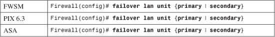
Each unit must be configured with its own failover identity, because no physical failover cable connection exists to differentiate them.
Note
Normally, you make configuration changes to only one firewall unit (the active one), and the changes are replicated automatically. In this step, each firewall must have a different keyword (primary or secondary) in its configuration to differentiate its firewall identity. Therefore, you must add this command to the primary and secondary firewalls independently.
b. (FWSM only) Allow the primary FWSM to preempt the secondary:
Firewall(config)# failover preempt [delay]
Normally, the firewall that has the active role keeps it until it fails or until you manually intervene. Beginning with FWSM 3.2(1), you can configure the primary FWSM to preempt its peer for control over the active role. With the failover preempt command, as soon as the primary FWSM boots up, it can preempt the secondary unit and take over the active role. By default, the primary unit preempts immediately. You can set a delay (1 to 1200 seconds) to force the primary unit to wait before assuming the active role.
c. Configure the LAN interface to be used:
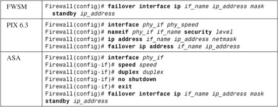
You need to configure the LAN interface for its name, speed, duplex, and security level on PIX 6.3 and ASA platforms. On any platform, you need to provide an IP address for the active unit and the standby unit.
On an ASA, the physical interface phy_if (ethernetn or gigabitethernetn) can be configured for only speed and duplex, which are both optional. The failover interface ip command assigns an IP address for the active and standby units according to an arbitrary interface name if_name. At this point, the interface name is not bound to a physical interface for LAN-based failover.
Note
Failover interfaces on FWSM and ASA platforms are not assigned IP addresses as part of interface configuration mode. This is because the active-active failover commands must be configured in the system execution space, which does not participate in IP communication.
In PIX 6.3, interface phy_if is of the form ethernetn (10/100) or gb-ethernetn (Gigabit Ethernet). The hardware_speed can be one of the following: 10baset (10 Mbps half duplex), 10full (10 Mbps full duplex), 100basetx (100 Mbps half duplex), 100full (100 Mbps full duplex), 1000auto (Gigabit autonegotiation), 1000full (Gigabit autonegotiation to use full duplex only), or 1000full nonegotiate (Gigabit full duplex). Assign an arbitrary interface named if_name (“lan-fo” or “failover,” for example) and a security level as securitylevel (0 to 100).
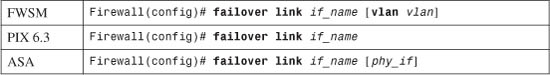
d. Identify the LAN interface used for failover communication:
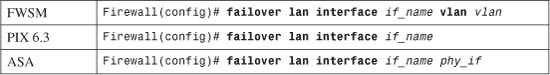
All failover communication is sent and received over the interface named if_name. On an ASA, you must also bind the failover LAN interface name to a physical interface phy_if (ethernetn or gigabitethernetn). On an FWSM, you must bind the failover LAN interface name to a VLAN number vlan.
Tip
With two FWSMs, the failover LAN interface is also a specific VLAN. If the two FWSMs are located in a single Catalyst 6500 chassis, the VLAN is used only internally within the chassis. If the two FWSMs are located in two separate switches, you must define this VLAN on and pass it between both switches. You can do this with a single-VLAN link or over a trunk link.
Before you can use the failover LAN interface VLAN, you must define it on the switch supervisor and then make it available to the FWSM by including it in the firewall vlan-group group-name vlan-list and firewall module module vlan-group group-name commands.
e. (Optional) Encrypt failover messages:
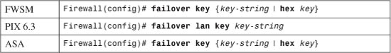
Because other stations might intercept or overhear traffic on the failover LAN, you can define a preshared key to make the failover traffic more secure. The key is used to authenticate the failover pair of firewalls, as well as to encrypt the failover information. You can define the key as key-string (an arbitrary text string up to 63 characters) or as a hexadecimal key (an arbitrary string of exactly 32 hex digits).
The key-string is not displayed in the firewall configuration after it is configured.
Obviously, the same key-string must be configured on both primary and secondary firewalls so that the failover traffic can be encrypted and unencrypted correctly between them. If the keys are not identical, you will see the following message on the firewall console:
WARNING: Failover message decryption failure. Please make sure both units have the same failover shared key and crypto license
f. Enable LAN-based failover:
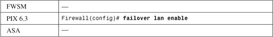
By default, a PIX failover pair expects to use the serial failover cable. You must start LAN-based failover explicitly with this command. From that point on, a connected serial cable is no longer used and can be removed.
On an ASA or FWSM, LAN-based failover is the only method for failover communication. Therefore, it is enabled by default.
4. (Active-active only) Define failover groups.
Failover groups must be configured from the system execution space on the primary firewall only.
a. Choose a failover group:
Firewall(config)# failover group {1 | 2}
Only two failover groups are supported. Because the failover mechanism in each group is independent, each group has its own active and standby roles. Contexts are assigned membership in one of the two groups listed in Step 9.
b. Prefer a firewall unit to have the active role:
Firewall(config-fover-group)# {primary | secondary}
In an initial condition, where the firewalls have booted up or failover has just been enabled, and both firewalls are functioning properly, one of them must be “elected” to take on the active failover role. By default, the primary unit has a higher priority to become active in each failover group.
You can designate a higher priority for the primary or secondary firewall unit with this command for the failover group being configured. Naturally, if that unit fails, the other unit still can take over the active role.
c. (Optional) Allow the higher-priority unit to assume immediate control:
Firewall(config-fover-group)# preempt
Normally, if an active unit fails, the standby unit assumes the active role indefinitely. The firewall units do not automatically revert to their original roles after a failure is resolved. Instead, they keep their roles until another failure occurs or there is manual intervention.
You can use the preempt command to allow the higher-priority unit in a failover group to always preempt the other unit for active control.
For example, suppose you have configured failover group 1 to give higher priority for the active role to the secondary unit. Normally, if the secondary unit fails, the primary unit assumes the active role and keeps it even after the secondary unit is restored. With preempt, the secondary unit can take over the active role as soon as it is restored to service. You would use the following commands to accomplish this:
Firewall(config)# failover group 1
Firewall(config-fover-group)# secondary
Firewall(config-fover-group)# preempt
5. (Optional) Use virtual MAC addresses for an interface:
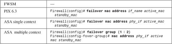
Normally, the active and standby units exchange information about their MAC addresses as a part of the regular failover messages. If the active unit goes down, the standby can replace the MAC addresses on all its interfaces with the previous active unit’s addresses. In the rare case where both units fail and the standby unit is rebooted alone, the standby unit has no knowledge of what the active MAC addresses should be. This is because the MAC address information was not exchanged between the units because of the failure.
This command allows both units to have stable information about what the active (active_mac) and standby (standby_mac) MAC addresses should be on an interface. In PIX 6.3, the interface name interface-name (outside, for example) is used, whereas an ASA uses the physical interface name (gigabit0, for example). Both addresses are given in dotted-triplet format, such as 0006.5b02.a841.
In ASA, the MAC addresses are defined as global values in single-context mode, where only active-standby failover applies. If the firewalls are operating in multiple-context mode, where active-active failover is used, the MAC addresses are configured within the failover group on the system execution space because two different failover groups of contexts are maintained.
Tip
To use the failover mac address command, you must be able to give unique MAC addresses to both the active and standby unit interfaces. Finding unique values is not always straightforward. An easy method is to display the burned-in addresses (BIAs) of all interfaces on the primary and secondary firewall units with the show interface command.
The addresses of the primary unit can always be assigned to the active firewall, and those of the secondary unit can be assigned to the standby firewall. After all, that is how the IP addresses are handled. Then, for each interface, use the command failover mac address interface primary_mac secondary_mac. At that point, it is usually a good idea to save the configurations and reboot both firewall units to make sure that the new MAC addresses are being used correctly.
If you are using LAN-based failover, the MAC addresses of that interface cannot be changed or defined using this command. Instead, the default BIAs of that interface are used. This is because even though the active and standby roles change during a failover, the primary and secondary roles do not. Therefore, the primary and secondary units must have consistent identities and interface addresses.
6. (Optional) Define a health monitoring policy.
a. Evaluate the health of the failover peer:
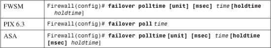
Each failover unit sends periodic hello messages to its peer over the serial failover cable or the LAN-based failover interface. This is offered as evidence that the unit is still alive.
In FWSM or PIX 6.3, you can adjust the hello message interval to time (3 to 15 seconds; the default is 15). On an ASA, you can use time (1 to 15 seconds; the default is 1) to give the interval in whole-second increments. You can also use msec time (500 to 999 milliseconds; the default is 500) to set the interval more granularly. Beginning with ASA 7.2(1), the minimum poll time is reduced to 200 milliseconds, making sub-second failover times possible.
The unit keyword can be used to denote hello timing between units or failover peers, rather than between individual interfaces. However, if unit is not given, it is assumed anyway; the keyword exists only to make the command easier for administrators to interpret.
One unit expects to receive hellos from its peer at regular intervals, although it does not know what that interval should be. If no hello messages are received before a holdtime timer expires, the other peer is considered to have failed. In ASA and FWSM, you can set that timer by adding holdtime holdtime (3 to 45 seconds; FWSM default is 45, ASA default is 15). PIX 6.3 uses a fixed holdtime that is always 3 times the hello interval. (The default is 3 times 15, or 45 seconds.) Beginning with ASA 7.2(1), you can add the msec keyword to set the holdtime in milliseconds (800 to 999 milliseconds).
The holdtime timer must always be set to a minimum of 3 times the unit hello interval. This is because the firewalls always check for the loss of at least three consecutive hellos from a peer before taking action. If the holdtime keyword is not given, the firewall adjusts the holdtime automatically. The only exception to this behavior is if the unit hello interval is set to 5 seconds or less, where the default holdtime is automatically set to 15 seconds. This is done to prevent very aggressive failure detection with very short hello intervals.
Tip
In ASA, the most aggressive peer monitoring policy has a unit interval of 200 milliseconds and a minimum holdtime of 800 milliseconds. This allows a standby unit to detect a failure with the active unit and take over its role within 800 milliseconds. In comparison, PIX 6.3 allows a minimum hello interval of 3 seconds, but with a minimum holdtime of 15 seconds.
Be careful if you decide to tighten up the unit and holdtime intervals for a more aggressive failure detection policy. Delayed or lost hellos on a congested LAN-based failover interface could be misinterpreted as a failure. If your LAN-based failover traffic is carried over switches that separate the two firewall units, make sure the switches are configured to use the most efficient spanning-tree and link-negotiation features possible. Otherwise, a Layer 2 topology change (a link or switch failure) could block the failover messages for up to 50 seconds!
b. Evaluate the health of interfaces:
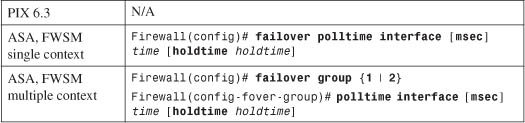
Failover hello messages are sent out firewall interfaces at time (3 to 15 seconds; FWSM default is 15, ASA default is 5) intervals. A corresponding holdtime timer exists. On an ASA, the holdtime can range from 5 to 75 seconds (default 5), while a FWSM uses 3 to 15 seconds (default 15) for interface monitoring.
In ASA, the interface polltime is a global value in single-context mode, where only active-standby failover applies. If the firewalls are operating in multiple-context mode, where active-active failover is used, polltime is configured within the failover group on the system execution space because two different failover groups of contexts are maintained.
With PIX 6.3, hello messages are sent out all connected interfaces at the same interval as failover unit hello messages. This interval is set with the failover poll command.
c. Define an interface failure policy:
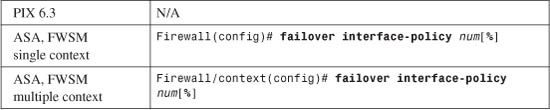
By default, if a firewall tests and finds that at least one of its monitored interfaces has failed, it declares itself failed. In that case, if the firewall was in active mode, the other unit takes over the active role.
To set the self-declared failure threshold, you can specify the number of failed interfaces as num (1 to the maximum number of interfaces; the default is 1) or a percentage of failed interfaces as num% (1 percent to 100 percent).
Notice that the interface failure policy is set on a per-context basis. On a single-context firewall, this is configured in global configuration mode. If multiple-context mode is running, you must connect to the appropriate security context and enter the command there.
7. (Optional) Use stateful failover for maximum availability.
Stateful failover can be used to synchronize the standby failover unit with connection information from the active unit. In this way, as connections are built or torn down, the standby unit can always keep its inspection tables up to date. If a failover occurs, the standby unit can take over the active role and maintain all the open connections without interruption.
Stateful failover requires a LAN connection between firewalls. This is to support the high bandwidth needed to carry updates about connections that are being inspected. Be aware that no stateful information is carried over the serial failover cable if one is being used to connect the firewalls.
a. Configure an interface to use for stateful update traffic:
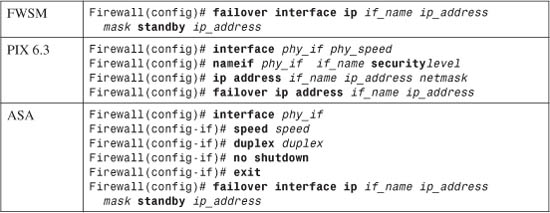
The stateful interface needs to be configured for its name, speed, duplex, and security level. It also needs an IP address for the active unit and the standby unit.
In ASA, the physical interface phy_if (ethernetn or gigabitethernetn) can be configured only for speed and duplex, which are both optional. The failover interface ip command assigns an IP address for the active and standby units according to an arbitrary interface name if_name. At this point, the interface name is not bound to a physical interface for stateful failover. This is done in Step 7c.
In PIX 6.3, interface phy_if is of the form ethernetn (10/100) or gb-ethernetn (Gigabit Ethernet). The hardware_speed can be one of the following: 10baset (10 Mbps half duplex), 10full (10 Mbps full duplex), 100basetx (100 Mbps half duplex), 100full (100 Mbps full duplex), 1000auto (Gigabit autonegotiation), 1000full (Gigabit autonegotiation to use full duplex only), or 1000full nonegotiate (Gigabit full duplex). Assign an arbitrary interface name if_name (“stateful,” for example) and a security level as securitylevel (0 to 100).
The two firewalls should have a dedicated link for this purpose, because stateful updates occur in real time as connections form or go away.
Tip
You can use one dedicated LAN interface (10/100 or Gigabit Ethernet) to carry both LAN-based failover and stateful failover information. The interface bandwidth must be large enough to carry the aggregate failover load.
However, it is always best to keep the LAN-based failover and stateful failover data streams on separate interfaces. The stateful failover data stream is usually much larger than the LAN-based failover because of the usually large number of connections that come and go. Therefore, you should set aside the fastest firewall interface that is available for stateful failover.
In addition, LAN-based failover messages must be able to travel between the two units without being lost or delayed. Otherwise, the loss of LAN-based failover messages indicates that one or both units have failed.
You can link the two stateful failover interfaces directly with a fiber-optic or crossover patch cord without connecting them to intermediate switches. However, neither firewall unit can determine which unit has had an interface failure, because the link status is lost on both units simultaneously.
The best-practice recommendations stress the need for an active device such as a switch to connect the stateful failover interfaces. If one unit loses an interface, a switch would keep the link status up for the other firewall unit.
In the case of FWSMs, they each have a 6-Gbps internal trunk link to the switch backplane. With their high performance, stateful failover information can easily burst up to the link bandwidth. Therefore, if two FWSMs are located in separate chassis, you should provide a stateful failover VLAN link of at least 6 Gbps. You can do this by aggregating Gigabit Ethernet links into a Gigabit EtherChannel.
b. Identify the interface used for stateful failover communication:
All stateful failover updates are sent and received over the interface named if_name (stateful, for example). Stateful failover can share the same interface as LAN-based failover if needed. However, you should always try to keep stateful and LAN-based failover isolated on two separate interfaces set aside for these purposes.
In ASA, you must also bind the interface name if_name (stateful, for example) to the physical interface name phy_if (gigabit0, for example). On a FWSM, you must bind the interface name if_name to a VLAN number vlan. If LAN-based and stateful failover share the same interface, the LAN-based failover lan interface command already configures this binding. In that case, the physical interface phy_if or VLAN vlan can be omitted from this command.
j. Keep stateful information about HTTP sessions:
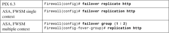
By default, connection state information is replicated to the standby unit for all TCP protocols except HTTP. The HTTP connections are unique because they are short-lived, usually lasting only as long as it takes to load a web page. If a firewall failover occurs, chances are that any active HTTP requests will be retried or new ones will be generated without any connection state information. However, if it is important that all HTTP connections be preserved across an actual firewall failover, use this command.
In ASA and FWSM, HTTP state replication is a global value in single-context mode, where only active-standby failover applies. If the firewalls are operating in multiple-context mode, where active-active failover is used, HTTP state replication is configured within the failover group on the system execution space because two different failover groups of contexts are maintained.
Tip
Beginning in ASA 8.0(1), session initiation protocol (SIP) signaling is also replicated between firewalls operating as a failover pair. FWSM 3.2 adds authentication, authorization, and accounting (AAA) state replication between a failover pair. These state replications are always enabled and cannot be configured.
8. Enable the failover process:
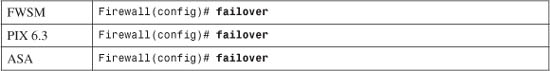
By default, failover is disabled even though you can configure the failover features. You must use the failover command to enable failover on the primary unit. Then, connect to the secondary unit and enter the command there too. After both units have failover enabled, they should discover each other and begin cooperating as a failover pair. At that time, the primary unit should begin replicating its configuration to the secondary unit.
As well, each of the configuration commands entered from this point on is automatically replicated from the active unit to the standby unit.
9. (Active-active only) Assign contexts to failover groups.
By default, all configured contexts belong to failover group 1. To assign the admin or a user context to a failover group, use the following commands in the system execution space:
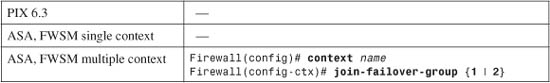
A context can be a member of only one failover group. You can repeat these commands to assign other contexts to a failover group.
10. Give each firewall interface an active and a standby IP address:
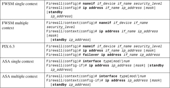
On the interface if_name, the active unit uses an IP address given by the ip address command. The standby unit uses a different address given by the failover ip address command or the standby keyword. After a failover occurs, the two units swap IP addresses so that the active unit always uses a consistent address. Although the standby interface is not active, it can respond to pings from other hosts to show that the unit is alive.
In ASA or FWSM multiple-context mode, most of the failover configuration must be done in the system execution space. However, to assign IP addresses to the various context interfaces, you need to connect to each context and configure them there. This applies to the admin context as well as any configured user contexts.
Note
Identical interfaces on the active and standby firewalls or contexts must have IP addresses that belong to the same network subnet. For example, if interface gigabit0 on the active unit is given 192.168.1.1 255.255.255.0 as its address, the standby unit’s gigabit0 interface must also belong to the 192.168.1.0/24 subnet.
11. (Optional) Identify interfaces to be monitored:
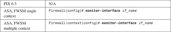
Before a firewall can measure a threshold of its own failed interfaces, you must identify each interface to be monitored. By default, all physical interfaces are monitored, but no logical interfaces (VLANs) are monitored. A firewall can monitor up to 250 interfaces.
You can enable monitoring on an interface by giving its name as if_name (outside, for example). If you want to disable monitoring on an interface, begin this command with the no keyword. This command can be repeated to identify more than one interface.
For active-active failover, interfaces are marked for monitoring in each of the configured admin and user contexts.
Tip
You can display a list of interfaces and their monitoring status with the show failover command. For example, the following output shows that the outside interface of the admin context and the inside and outside interfaces of the CustomerA context are being monitored. The interfaces of the CustomerB context are not:
Firewall# show failoverFailover OnCable status: N/A - LAN-based failover enabledFailover unit PrimaryFailover LAN Interface: Failover Ethernet0 (up)Unit Poll frequency 3 seconds, holdtime 9 secondsInterface Poll frequency 15 secondsInterface Policy 1Monitored Interfaces 4 of 250 maximumGroup 1 last failover at: 15:33:52 EST Dec 1 2004Group 2 last failover at: 12:33:40 EST Nov 30 2004 This host: Primary Group 1 State: Standby Ready Active time: 233703 (sec) Group 2 State: Active Active time: 168885 (sec)admin Interface outside (192.168.93.141): NormalCustomerA Interface outside (192.168.93.142): NormalCustomerA Interface inside (192.168.200.11): NormalCustomerB Interface inside (192.168.220.10): Normal (Not-Monitored)CustomerB Interface outside (192.168.200.12): Normal (Not-Monitored) Other host: Secondary Group 1 State: Active Active time: 71814 (sec) Group 2 State: Standby Ready Active time: 136665 (sec)admin Interface outside (192.168.93.138): NormalCustomerA Interface outside (192.168.93.139): NormalCustomerA Interface inside (192.168.200.10): NormalCustomerB Interface inside (192.168.220.11): Normal (Not-Monitored)CustomerB Interface outside (192.168.200.13): Normal (Not-Monitored)
8-3 Firewall Failover Configuration Examples
This section presents several examples of firewall failover configuration, each with a different set of platforms or failover modes. In each example, two firewalls are configured as a failover pair. Each interface from the failover pair connects to a separate switch or VLAN so that the failover feature can exchange hello messages and detect failures.
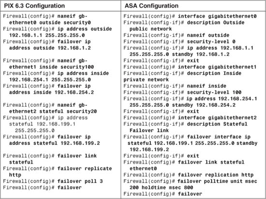
Active-Standby Failover Example with PIX Firewalls
Figure 8-7 shows the IP addresses of each interface. The addresses of the standby unit interfaces are also given. Stateful failover is used so that connection state information is passed to the standby unit in real time. An example of failover using the serial failover cable is shown first, followed by a LAN-based failover scenario. Following the failover guidelines, a separate VLAN or switch is used for stateful failover (the “stateful” interface) and for LAN-based failover (the “lanfo” interface) information exchange.
Figure 8-7 Network Diagram for the Active-Standby Example
The failover pair is configured to use the most aggressive peer monitoring policy possible, using a peer hello interval of 3 seconds on PIX 6.3 and 200 milliseconds on ASA.
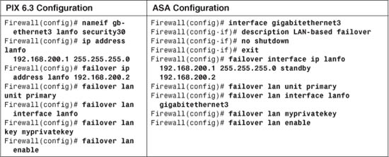
Preliminary configuration for stateful failover using is as follows:
Additional configuration for the primary LAN-based failover unit is as follows:
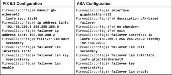
Now, a session is opened to the secondary failover unit, and the following additional configuration commands are added to it:
Active-Standby Failover Example with FWSM
Now, suppose these firewalls are actually FWSMs. Suppose the inside interface uses VLAN 100, outside uses VLAN 200, stateful uses 300, and lanfo uses 400. The configuration for the primary FWSM in slot 3 would look like this, beginning with the necessary Catalyst 6500 commands:
Switch(config)# vlan 100,200,300,400
Switch(config)# firewall vlan-group 1 100,200,300,400
Switch(config)# firewall module 3 vlan-group 1
Switch(config)# exit
! Now open a session to the FWSM itself
Switch# session slot 3 processor 1
Next are the FWSM commands:
fwsm(config)# nameif vlan100 inside security100
fwsm(config)# ip address inside 192.168.254.1 255.255.255.0 standby 192.168.254.2
fwsm(config)# nameif vlan200 outside security0
fwsm(config)# ip address outside 192.168.1.1 255.255.255.0 standby 192.168.1.2
fwsm(config)# failover interface ip stateful 192.168.199.1 255.255.255.0 standby
192.168.199.2
fwsm(config)# failover link stateful vlan 300
fwsm(config)# failover interface ip lanfo 192.168.200.1 255.255.255.0 standby
192.168.200.2
fwsm(config)# failover lan unit primary
fwsm(config)# failover lan interface lanfo vlan 400
fwsm(config)# failover replication http
fwsm(config)# failover polltime unit msec 500 holdtime 3
fwsm(config)# failover
Then, on the secondary FWSM in the module 4 slot, the following configuration commands are entered, beginning with the Catalyst 6500 session. Note that the first two switch commands are entered again only if the two FWSMs are located in separate switch chassis. If the FWSMs are housed in the same switch chassis, the VLANs and the firewall VLAN group are already configured:
Switch(config)# vlan 100,200,300,400
Switch(config)# firewall vlan-group 1 100,200,300,400
Switch(config)# firewall module 4 vlan-group 1
Switch(config)# exit
! Now open a session to the FWSM itself
Switch# session slot 4 processor 1
[output omitted]
fwsm(config)# failover interface ip stateful 192.168.199.1 255.255.255.0 standby
192.168.199.2
fwsm(config)# failover link stateful vlan 300
fwsm(config)# failover interface ip lanfo 192.168.200.1 255.255.255.0 standby
192.168.200.2
fwsm(config)# failover lan unit secondary
fwsm(config)# failover lan interface lanfo vlan 400
fwsm(config)# failover
Active-Active Failover Example
Suppose a Cisco firewall is to be configured with multiple security contexts so that it can provide firewall services to two customers of a service provider. A total of three contexts are needed:
• admin
• CustomerA
• CustomerB
To enhance the availability of the firewall contexts, a second firewall is added to form a failover pair. Active-active failover is used so that one firewall has the active role for some contexts and the other firewall is active for a different set of contexts.
Figure 8-8 shows a basic diagram for this arrangement. The primary and secondary firewalls use LAN-based failover communication over their Ethernet0/0 interfaces. The firewalls send failover hello messages once every second and wait for 3 seconds before declaring their peer failed. Stateful failover carries connection state information between the firewalls over their GigabitEthernet1/2 interfaces.
Tip
This example uses interface names that are relevant to ASA platforms with a four-port GigabitEthernet module. The same example can apply to FWSM platforms, by substituting VLANs for physical interface names.
One path to the public network is provided over the firewalls’ GigabitEthernet1/0 interfaces. This connection becomes the outside interface for each of the security contexts so that they share a common pipe to the public Internet.
Each security context has its own separate inside interface, which is carried as a VLAN over the GigabitEthernet1/1 trunking firewall interfaces. VLAN 10 is assigned to the admin context, VLAN 20 to the CustomerA context, and VLAN 30 to the CustomerB context.
Finally, two failover groups are used to allow the two firewalls to have differing roles in the contexts. Failover group 1 gives preference to the primary unit having the active role. The admin and CustomerA contexts are members of group 1. Failover group 2 gives preference to the secondary unit having the active role, where the CustomerB context is a member.
Figure 8-8 Network Diagram for the Active-Active Example
Remember that each interface of the primary firewall is “connected” to the corresponding interface of the secondary firewall. In other words, the two firewalls have their corresponding interfaces assigned to the same VLANs so that failover messages can be exchanged between the firewall units over each of their interfaces. This is required for failover operation.
Active-active failover can be difficult to visualize and configure. The configuration for this example is broken into several steps, as described in the following sections.
Primary Firewall Configuration
First, you need to configure the primary firewall. Remember that failover is configured in the system execution space of a multiple-context firewall.
1. Begin with only the interfaces needed for failover.
The GigabitEthernet1/2 (stateful failover) and Ethernet0 (LAN-based failover) interfaces are needed. Their configuration is not necessary, because the actual failover commands remove any IP addressing or other parameters that might be assigned in interface configuration mode. They are shown here only for clarity:
Firewall(config)# mode multiple
[output omitted]
! Here, the system execution space is being configured
!
Firewall(config)# interface gigabitethernet1/2
Firewall(config-if)# description Stateful failover interface
Firewall(config-if)# exit
Firewall(config)# interface ethernet0/0
Firewall(config-if)# description LAN-based failover interface
Firewall(config-if)# exit
2. Configure LAN-based failover:
Firewall(config)# failover lan unit primary
Firewall(config)# failover lan interface LAN-fo ethernet0/0
Firewall(config)# failover interface ip LAN-fo 192.168.1.1 255.255.255.0
standby 192.168.1.2
Firewall(config)# failover polltime unit 1 holdtime 3
Firewall(config)# failover key *****
Firewall(config)# failover lan enable
3. Configure stateful failover:
Firewall(config)# failover interface ip Stateful 192.168.2.1 255.255.255.0
standby 192.168.2.2
Firewall(config)# failover link Stateful gigabitethernet1/2
4. Define the failover groups:
Firewall(config)# failover group 1
Firewall(config-fover-group)# primary
Firewall(config-fover-group)# preempt
Firewall(config-fover-group)# exit
Firewall(config)# failover group 2
Firewall(config-fover-group)# secondary
Firewall(config-fover-group)# preempt
Firewall(config-fover-group)# exit
5. Enable failover:
Firewall(config)# failover
Secondary Firewall Configuration
1. Begin with only the interfaces needed for failover.
The GigabitEthernet1/2 (stateful failover) and Ethernet0/0 (LAN-based failover) interfaces are paired with identical interfaces on the primary firewall. Their configuration is not necessary; it is shown here only for clarity:
Firewall(config)# mode multiple
[output omitted]
! Here, the system execution space is being configured
!
Firewall(config)# interface gigabitethernet1/2
Firewall(config-if)# description Stateful failover interface
Firewall(config-if)# exit
Firewall(config)# interface ethernet0/0
Firewall(config-if)# description LAN-based failover interface
Firewall(config-if)# exit
2. Configure LAN-based failover.
Here, the secondary unit begins its life in standby mode for all failover groups. Therefore, it knows to pick up the standby IP address for the LAN-based and stateful failover interfaces in the following commands:
Firewall(config)# failover lan unit secondary
Firewall(config)# failover lan interface LAN-fo ethernet0/0
Firewall(config)# failover interface ip LAN-fo 192.168.1.1 255.255.255.0
standby 192.168.1.2
Firewall(config)# failover polltime unit 1 holdtime 3
Firewall(config)# failover key *****
Firewall(config)# failover lan enable
3. Configure stateful failover:
Firewall(config)# failover interface ip Stateful 192.168.2.1 255.255.255.0
standby 192.168.2.2
Firewall(config)# failover link Stateful gigabitethernet1/2
4. Define the failover groups.
Although the failover groups could be explicitly configured here, as they were on the primary firewall unit, that is not really necessary. The failover group configuration is replicated to the secondary unit as soon as failover is enabled on each. The following commands become a part of the configuration:
Firewall(config)# failover group 1
Firewall(config-fover-group)# primary
Firewall(config-fover-group)# preempt
Firewall(config)# exit
Firewall(config)# failover group 2
Firewall(config-fover-group)# secondary
Firewall(config-fover-group)# preempt
Firewall(config)# exit
5. Enable failover:
Firewall(config)# failover
Allocating Interfaces to the Contexts
Configuration should continue on the primary firewall in the system execution space. As soon as failover is enabled on both firewalls and is operational, any remaining configuration commands are replicated to the secondary unit automatically. This saves time and effort over entering the same commands in the two firewalls manually.
1. Define physical interfaces in the system execution space.
Here, you identify the interfaces. You also configure the subinterfaces of GigabitEthernet1/1 with their VLAN numbers on the trunk. No IP addresses are assigned in the system execution space. Rather, the addressing is left up to the administrator of the context where each interface will be allocated:
Firewall(config)# interface gigabitethernet1/0
Firewall(config-if)# description Public Network for all contexts
Firewall(config-if)# exit
!
Firewall(config)# interface gigabitethernet1/1
Firewall(config-if)# description Trunk for non-public networks
Firewall(config-if)# exit
!
Firewall(config)# interface gigabitethernet1/1.10
Firewall(config-if)# description Private network for admin context
Firewall(config-if)# vlan 10
Firewall(config-if)# exit
!
Firewall(config)# interface gigabitethernet1/1.20
Firewall(config-if)# description Private network for CustomerA context
Firewall(config-if)# vlan 20
Firewall(config-if)# exit
!
Firewall(config)# interface gigabitethernet1/1.30
Firewall(config-if)# description Private network for CustomerB context
Firewall(config-if)# vlan 30
Firewall(config-if)# exit
2. Allocate interfaces to the contexts and failover groups.
For the admin context, you can allocate interfaces only with their physical interface names. For the CustomerA and CustomerB user contexts, however, you can assign logical names (intf0 and intf1) so that the physical identity remains hidden:
Firewall(config)# context admin
Firewall(config-ctx)# allocate-interface gigabitethernet1/0
Firewall(config-ctx)# allocate-interface gigabitethernet1/1.10
Firewall(config-ctx)# config-url flash:/admin.cfg
Firewall(config-ctx)# join-failover-group 1
Firewall(config-ctx)# exit
!
Firewall(config)# context CustomerA
Firewall(config-ctx)# description Virtual firewall for CustomerA
Firewall(config-ctx)# allocate-interface gigabitethernet1/0 intf0
Firewall(config-ctx)# allocate-interface gigabitethernet1/1.20 intf1
Firewall(config-ctx)# config-url flash:/CustomerA.cfg
Firewall(config-ctx)# join-failover-group 1
Firewall(config-ctx)# exit
!
Firewall(config)# context CustomerB
Firewall(config-ctx)# description Virtual firewall for CustomerB
Firewall(config-ctx)# allocate-interface gigabitethernet1/0 intf0
Firewall(config-ctx)# allocate-interface gigabitethernet1/1.30 intf1
Firewall(config-ctx)# config-url flash:/CustomerB.cfg
Firewall(config-ctx)# join-failover-group 2
Firewall(config-ctx)# exit
Configuring Interfaces in Each Context
After you have allocated the physical firewall interfaces to the security contexts, you must configure them for use by the contexts. You do this by opening a session to each context in turn. At this point, remember that the context is a virtual firewall, so each interface needs an IP address, a security level, and a name. Also remember that each context has its own concept of failover. Each interface needs a standby IP address, too.
1. Configure the admin context interfaces:
Firewall# change to context admin
Firewall/admin# configure terminal
Firewall/admin(config)# interface gigabitethernet1/0
Firewall/admin(config-if)# nameif outside
Firewall/admin(config-if)# security-level 0
Firewall/admin(config-if)# ip address 192.168.93.1 255.255.255.0 standby
192.168.93.2
Firewall/admin(config-if)# exit
!
Firewall/admin(config)# interface gigabitethernet1/1.10
Firewall/admin(config-if)# nameif inside
Firewall/admin(config-if)# security-level 100
Firewall/admin(config-if)# ip address 192.168.1.1 255.255.255.0 standby
192.168.1.2
Firewall/admin(config-if)# exit
Firewall/admin(config)# exit
2. Configure the CustomerA context interfaces:
Firewall/admin# changeto context CustomerA
Firewall/CustomerA# configure terminal
Firewall/CustomerA(config)# interface intf0
Firewall/CustomerA(config-if)# nameif outside
Firewall/CustomerA(config-if)# security-level 0
Firewall/CustomerA(config-if)# ip address 192.168.93.140 255.255.255.0
standby 192.168.93.141
Firewall/CustomerA(config-if)# exit
!
Firewall/CustomerA(config)# interface intf1
Firewall/CustomerA(config-if)# nameif inside
Firewall/CustomerA(config-if)# security-level 100
Firewall/CustomerA(config-if)# ip address 192.168.200.10 255.255.255.0
standby 192.168.200.11
Firewall/CustomerA(config-if)# exit
Firewall/CustomerA(config)# exit
3. Configure the CustomerB context interfaces:
Firewall/CustomerA# changeto context CustomerB
Firewall/CustomerB# configure terminal
Firewall/CustomerB(config)# interface intf0
Firewall/CustomerB(config-if)# nameif outside
Firewall/CustomerB(config-if)# security-level 0
Firewall/CustomerB(config-if)# ip address 192.168.93.150 255.255.255.0
standby 192.168.93.151
Firewall/CustomerB(config-if)# exit
!
Firewall/CustomerB(config)# interface intf1
Firewall/CustomerB(config-if)# nameif inside
Firewall/CustomerB(config-if)# security-level 100
Firewall/CustomerB(config-if)# ip address 192.168.220.10 255.255.255.0
standby 192.168.220.11
Firewall/CustomerB(config-if)# exit
Firewall/CustomerB(config)# exit
8-4 Managing Firewall Failover
By nature, firewall failover is a feature that can take action automatically, based on whether two firewalls are operational and connected. You might want to monitor or troubleshoot the failover mechanism on a failover pair so that you can verify its operation. As well, there might be occasions when you need to manually force the failover action between the peers. The following sections cover these topics.
Displaying Information About Failover
When you connect to a firewall remotely, it is not always apparent which unit is the active one. Because the active unit configuration is replicated to the standby unit, the command-line prompt (and the underlying host name) is identical on both units. This can make interacting with the correct firewall very difficult.
After you connect to a firewall, use the show failover command to determine the state of that unit, as shown in the following example:
Firewall# show failover
Failover On
Cable status: Normal
Reconnect timeout 0:00:00
Poll frequency 15 seconds
This host: Primary - Active
Active time: 2421015 (sec)
Interface stateful (192.168.199.1): Normal
Interface dmz2 (127.0.0.1): Link Down (Shutdown)
Interface outside (192.168.1.1): Normal
Interface inside (192.168.254.1): Normal
Other host: Secondary - Standby
Active time: 0 (sec)
Interface stateful (192.168.199.2): Normal
Interface dmz2 (0.0.0.0): Link Down (Shutdown)
Interface outside (192.168.1.2): Normal
Interface inside (192.168.254.2): Normal
Remember that you should make configuration changes to only the active unit, because those changes are replicated in only one direction—active to standby. Active-active failover takes this one step further—configuration changes to the system execution space or the admin context must be made on the firewall unit that is active for failover group 1. If you attempt to configure the standby unit, the standby firewall displays a warning that the configurations are no longer synchronized.
In the case of active-active failover, this gets a little more complicated. Now, a firewall can be either the primary or secondary unit, but it can be active in some contexts while being standby in others. You can find out which failover group the firewall is active in by using the show failover command in the system execution space, as shown in the following example:
Firewall# show failover
Failover On
Cable status: N/A - LAN-based failover enabled
Failover unit Primary
Failover LAN Interface: Failover Ethernet0/2 (up)
Unit Poll frequency 3 seconds, holdtime 9 seconds
Interface Poll frequency 15 seconds
Interface Policy 1
Monitored Interfaces 3 of 250 maximum
Group 1 last failover at: 13:10:46 EST Dec 9 2004
Group 2 last failover at: 13:10:04 EST Dec 9 2004
This host: Primary
Group 1 State: Active
Active time: 149706 (sec)
Group 2 State: Standby Ready
Active time: 121650 (sec)
[output omitted]
Other host: Secondary
Group 1 State: Standby Ready
Active time: 120936 (sec)
Group 2 State: Active
Active time: 148995 (sec)
If you cannot enable failover, check the status of your firewall license with the show activation-key or show version command. The following example shows the results for an ASA firewall:
Firewall# show activation-key
Serial Number: JHX1114L04Z
Running Activation Key: 0x7411c36d 0x639a94fa 0xa3f0b034 0x913c0374 0x3f3632ba
License Features for this Platform:
Maximum Physical Interfaces : Unlimited
Maximum VLANs : 100
Inside Hosts : Unlimited
Failover : Active/Active
VPN-DES : Enabled
VPN-3DES-AES : Enabled
Security Contexts : 5
GTP/GPRS : Enabled
VPN Peers : Unlimited
WebVPN Peers : 2
Advanced Endpoint Assessment: Disabled
This platform has an ASA 5510 Security Plus license.
The flash activation key is the SAME as the running key.
Firewall#
Displaying the Current Failover Status
You can use the following command to display a summary of the current failover status:
Firewall# show failover
The output from this command displays the configured failover state (on or off), along with failover cable status, the last failover date and time, the failover roles (primary or secondary) for both units, the firewall role (active or standby) for both units, the status of each configured interface, and the statistics for the stateful failover link (if configured).
An ASA or FWSM also presents this information for each failover group (1 and 2). Within each group, the status of each of the security contexts and its allocated interfaces are shown. For example, the system execution space on the primary firewall has the following output. Notice that at a glance, the shaded text gives a snapshot of every state and role involved in failover:
Firewall# show failover
Failover On
Cable status: N/A - LAN-based failover enabled
Failover unit Primary
Failover LAN Interface: Failover Ethernet2 (up)
Unit Poll frequency 3 seconds, holdtime 9 seconds
Interface Poll frequency 15 seconds
Interface Policy 1
Monitored Interfaces 3 of 250 maximum
Group 1 last failover at: 13:11:02 EST Dec 7 2004
Group 2 last failover at: 15:01:04 EST Dec 7 2004
This host: Primary
Group 1 State: Active
Active time: 7536 (sec)
Group 2 State: Standby Ready
Active time: 663 (sec)
admin Interface outside (192.168.93.138): Normal
CustomerA Interface outside (192.168.93.139): Normal
CustomerA Interface inside (192.168.200.10): Normal
(Not-Monitored)
CustomerB Interface outside (192.168.93.143): Normal
CustomerB Interface inside (192.168.220.11): Normal
(Not-Monitored)
Other host: Secondary
Group 1 State: Standby Ready
Active time: 0 (sec)
Group 2 State: Active
Active time: 6879 (sec)
admin Interface outside (128.163.93.141): Normal
CustomerA Interface outside (128.163.93.142): Normal
CustomerA Interface inside (192.168.200.11): Normal
(Not-Monitored)
CustomerB Interface outside (128.163.93.140): Normal
CustomerB Interface inside (192.168.220.10): Normal
(Not-Monitored)
Stateful Failover Logical Update Statistics
Link : Failover Ethernet2 (up)
Stateful Obj xmit xerr rcv rerr
General 135508407 7 53412868 0
sys cmd 266210 0 266207 0
up time 14 0 0 0
RPC services 0 0 0 0
TCP conn 123228648 0 47758798 0
UDP conn 663934 0 448445 0
ARP tbl 6 0 0 0
Xlate_Timeout 617643 0 556745 0
Logical Update Queue Information
Cur Max Total
Recv Q: 0 35 7519538
Xmit Q: 0 1 18562497
Firewall#
The Stateful Failover Logical Update Statistics represent the number of connection or table synchronization update messages that the firewall has transmitted and received. The Logical Update Queue Information shows the number of stateful update messages that have been queued as they have been transmitted to or received from the failover peer. Nonzero values mean that more updates have been queued than could be processed. A large value might indicate that the stateful failover bandwidth needs to be increased, usually by choosing a faster interface.
To see the failover status information for just one failover group, you can use the following command:
Firewall# show failover group {1 | 2}
On an ASA or FWSM, you can also get a quick summary of the failover status with the following command:
Firewall# show failover state
In the following example, the firewall is shown to be the primary unit with the active role, and the other peer is the secondary in standby. The configurations are synchronized, and the interface MAC addresses have been set according to the primary and secondary burned-in addresses. If one of the units had failed, a reason would be shown:
Firewall# show failover state
====My State===
Primary | Active |
====Other State===
Secondary | Standby |
====Configuration State===
Sync Done
====Communication State===
Mac set
=========Failed Reason==============
My Fail Reason:
Other Fail Reason:
Firewall#
Displaying the LAN-Based Failover Interface Status
An FWSM or an ASA cannot display LAN-based failover interface statistics. However, a firewall running PIX 6.3 displays this information if you use the following command:
Firewall# show failover lan [detail]
For example, in the following output, the LAN-based failover interface is called lan-fo. It uses 192.168.1.1 and 192.168.1.2 on the two peers:
Firewall# show failover lan
LAN-based Failover is Active
interface lan-fo (192.168.1.1): Normal, peer (192.168.1.2): Normal
Firewall#
You could see much more detail about the interface activity by adding the detail keyword, as shown in the following example. Notice that statistics are kept for the number of failover messages sent, received, dropped, and so on, as well as the response times for message exchanges with the failover peer (the shaded text):
Firewall# show failover lan detail
LAN-based Failover is Active
This PIX is Primary
Command Interface is lan-fo
My Command Interface IP is 192.168.198.1
Peer Command Interface IP is 192.168.198.2
My interface status is Normal
Peer interface status is Normal
Peer interface down time is 0x0
Total cmd msgs sent: 107856, rcvd: 107845, dropped: 1, retrans: 8, send_err: 0
Total secure msgs sent: 147375, rcvd: 147301
bad_signature: 0, bad_authen: 0, bad_hdr: 0, bad_osversion: 0, bad_length: 0
Total failed retx lck cnt: 0
Total/Cur/Max of 52719:0:3 msgs on retransQ, 52718 ack msgs
Cur/Max of 0:7 msgs on txq
Cur/Max of 0:34 msgs on rxq
Number of blk allocation failure: 0, cmd failure: 0, Flapping: 0
Current cmd window: 3, Slow cmd Ifc cnt: 0
Cmd Link down: 17, down and up: 0, Window Limit: 17266
Number of fmsg allocation failure: 0, duplicate msgs: 0
Cmd Response Time History stat:
< 100ms: 52681
100 - 250ms: 12
250 - 500ms: 13
500 - 750ms: 12
750 - 1000ms: 0
1000 - 2000ms: 4
2000 - 4000ms: 1
> 4000ms: 3
Cmd Response Retry History stat:
Retry 0 = 52719, 1 = 4, 2 = 1, 3 = 1, 4 = 1
[output truncated]
Displaying a History of Failover State Changes
A firewall keeps a running history of each time its failover state changes. Although the history events are not recorded with a timestamp, the sequence of events can still be useful information. For example, if failover did not come up correctly, you could trace through the history to see the sequence of state changes and the cause for each. You can see the history with the following command:
Firewall# show failover history
For example, the following output shows the failover state change history for a firewall running in multiple-context mode. Failover groups 0 (for system execution space failover), 1, and 2 are listed, because failover operates independently in each group. This sequence of state changes occurred as failover was configured for the first time. During the No Active unit found changes, the secondary peer had not yet been configured for failover.
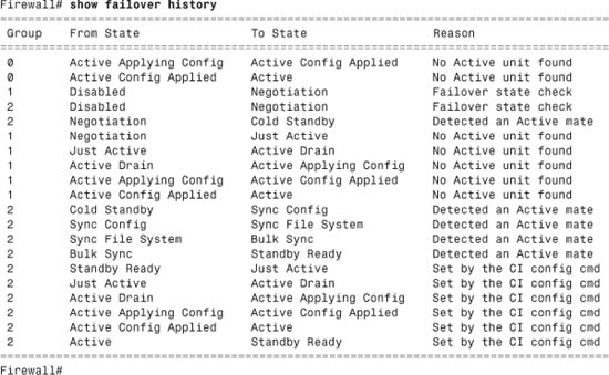
Debugging Failover Activity
Table 8-1 summarizes some of the commands you can use to generate debugging information about firewall failover operation.
Table 8-1 debug Commands Relevant to Firewall Failover Operation
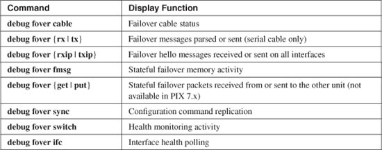
Tip
Commands using the debug keyword produce real-time output for troubleshooting purposes. To see these messages, you must first enable logging output to the firewall console (logging console), to a Telnet or SSH session (logging monitor), to a logging buffer (logging buffered), or to a Syslog server (logging host). The debug output also must be sent to the Syslog destination with the logging debug-trace configuration command. See Chapter 10, “Firewall Logging,” for more information.
Monitoring Stateful Failover
As soon as stateful failover is enabled, you should make sure your stateful failover interface is not being overrun with stateful information packets. In other words, verify that the stateful interface bandwidth is sufficient for the load. Otherwise, information about some active connections will not be passed from the active to the standby firewall. If a failover occurs, these unknown connections are terminated.
In single-context mode, you can make a quick manual estimate by using the show traffic command. Unfortunately, this command shows only cumulative values collected since the traffic counters were last cleared. For the packets-per-second and bytes-per-second values, a running average is computed since the counters were last cleared.
However, you can issue the clear traffic command on the active firewall to clear the counters, wait 10 seconds, and issue the show traffic command. You should do this during a peak load time so that you see a snapshot of the busiest stateful information exchange. The following example shows how this is done:
Firewall# clear traffic
[wait 10 seconds]
Firewall# show traffic
stateful:
received (in 9.050 secs):
3 packets 395 bytes
0 pkts/sec 43 bytes/sec
transmitted (in 9.050 secs):
84 packets 98682 bytes
9 pkts/sec 10904 bytes/sec
[output deleted]
In multiple-context mode (active-active failover), things get a little more difficult. The interface used for stateful failover is defined and configured only in the system execution space, where there is no show traffic command. (That command is available in each security context; however, the stateful failover interface is not!)
To gauge the stateful failover interface usage, you can use the show interface command instead. Issue that command and note the number of bytes shown. (This is a cumulative total, not a bytes-per-second rate.) Then, wait 10 seconds and issue the command again. Note the new byte count, subtract the two, and divide by 10. This gives you an estimate of the bytes per second being sent and received over the stateful interface.
You can also use ASDM to generate statistics or a utilization graph of a stateful LAN interface. Running the graph over a period of time shows you the maximum bit rate that has been used to transfer stateful information. Figure 8-9 shows a sample ASDM graph.
Figure 8-9 Using ASDM to Gauge Stateful Failover Traffic
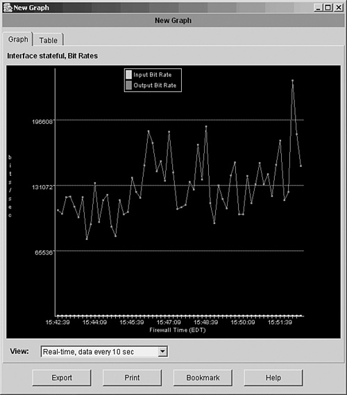
Finally, the firewall performance itself affects the stateful failover operation. As stateful messages are generated, they are put into 256-byte memory blocks and placed in a queue before being sent to the failover peer. If the firewall cannot generate and send the stateful messages as fast as they are needed, more memory blocks are used. Although the firewall can allocate more 256-byte blocks as needed, the supply of these blocks can be exhausted in an extreme case.
You can use the show blocks command as a gauge of the stateful failover performance. Over time, the 256-byte block “CNT” value should remain above 0. If it continues to hover around 0, the active firewall cannot keep the connection state information synchronized with the standby firewall. Most likely, a higher-performance firewall is needed.
Manually Intervening in Failover
When the firewalls in a failover pair detect a failure and take action, they do not automatically revert to their original failover roles. For example, if the primary firewall is active and then fails, it is marked as failed, and the secondary firewall takes over the active role. After the primary unit is repaired and returned to service, it does not automatically reclaim the active role (unless it has been configured to preempt active control).
You might occasionally find that you need to manually intervene in the failover process to force a role change or to reset a failover condition. The commands discussed in the following sections should be used from configuration mode in single-context mode and in the system execution space in multiple-context mode.
Forcing a Role Change
Ordinarily, the firewalls fail over to each other automatically, without any intervention. However, they do not automatically fail back to their original roles. If for some reason you need to force one unit to become active again, you can use the following privileged EXEC command:
Firewall# [no] failover active [group {1 | 2}]
You can also force a unit into standby mode with the no failover active command.
With active-active failover, you can specify the failover group (1 or 2) that will become active. For example, suppose the secondary firewall should be standby for failover group 1 and active for failover group 2. After a failure, it ends up in standby mode for both failover groups, as shown in the following output:
Firewall# show failover
Failover On
Cable status: N/A - LAN-based failover enabled
Failover unit Primary
Failover LAN Interface: Failover Ethernet0/2 (up)
Unit Poll frequency 3 seconds, holdtime 9 seconds
Interface Poll frequency 15 seconds
Interface Policy 2
Monitored Interfaces 3 of 250 maximum
Group 1 last failover at: 10:29:18 EST Jan 30 2005
Group 2 last failover at: 16:18:28 EST Mar 9 2005
This host: Secondary
Group 1 State: Standby Ready
Active time: 3311601 (sec)
Group 2 State: Standby Ready
Active time: 3304092 (sec)
To restore the secondary unit to the active role for failover group 2, you could take two different approaches:
• Force the primary unit (currently active) into the standby role by using the no failover active group 2 command
• Force the secondary unit (currently standby) into the active role by using the failover active group 2 command
Resetting a Failed Firewall Unit
If a firewall has been marked as failed but has been repaired or its connectivity restored, you might have to manually “unfail” it or reset its failover role. You can use the following privileged EXEC command:
Firewall# failover reset [group {1 | 2}]
You can use this command on either the active or failed unit. If it is issued on the active unit, the command is replicated to the failed unit, and only that unit’s state is reset. In active-active failover, you can add the group keyword and failover group number for the firewall role to be reset.
Reloading a Hung Standby Unit
Sometimes, an active and standby firewall can communicate over a failover connection but cannot synchronize their failover operation. In this case, you can manually force the standby unit to reload and reinitialize its failover role with the following command:
Firewall# failover reload-standby
After the reload, it should resynchronize with the active unit.
Executing Commands on a Failover Peer
Although two firewalls can be configured as a failover pair, they still support their own administrative sessions independently. For example, you can connect to the active unit and enter commands, make configuration changes, and so on. The same is true of the standby unit, where you can connect and do everything except make configuration changes.
Sometimes you might find yourself connected to one unit when you would like to do something on the other unit. Normally you would have to open up an administrative connection to the other unit and enter your commands there. Beginning with ASA 8.0(1), you can open a single session and enter commands that are passed to the failover peer and evaluated there.
Use the following EXEC command to send a command string to the appropriate failover unit:
Firewall# failover exec {active | standby | mate} cmd_string
Regardless of the unit to which you are connected, you can send a command line, cmd_string, to any of the following failover pair units:
• active—The command is sent to the current active unit, where it is executed and also replicated to the standby unit.
• standby—The command is sent to the current standby unit, where it is executed; it is not replicated to the active unit.
• mate—The command is sent to the mate or peer of the unit, where the command is entered.
For example, suppose you are connected to the active unit, where you can display its activation key with the show activation-key command. Then, without opening a second connection to the standby unit, you can see the standby unit’s flash file system by sending it the same command, too, as in the following example:
Firewall# show activation-key
Serial Number: 848020184
Running Activation Key: 0x7111c56d 0x689a94fa 0xa4f0b064 0x910c0474 0xcf36c2ba
Licensed features for this platform:
Maximum Physical Interfaces : 6
Maximum VLANs : 25
Inside Hosts : Unlimited
Failover : Active/Active
VPN-DES : Enabled
VPN-3DES-AES : Enabled
Cut-through Proxy : Enabled
Guards : Enabled
URL Filtering : Enabled
Security Contexts : 5
GTP/GPRS : Enabled
VPN Peers : Unlimited
This platform has an Unrestricted (UR) license.
The flash activation key is the SAME as the running key.
Firewall#
Firewall# failover exec standby show activation-key
Serial Number: 857206105
Running Activation Key: 0xb116c169 0xd0f16030 0x44600c98 0xb138e8b0 0x8322dc9f
Licensed features for this platform:
Maximum Physical Interfaces : 6
Maximum VLANs : 25
Inside Hosts : Unlimited
Failover : Active/Active
VPN-DES : Enabled
VPN-3DES-AES : Enabled
Cut-through Proxy : Enabled
Guards : Enabled
URL Filtering : Enabled
Security Contexts : 5
GTP/GPRS : Enabled
VPN Peers : Unlimited
This platform has an Unrestricted (UR) license.
The flash activation key is the SAME as the running key.
Firewall#
You should keep a couple things in mind about remotely executing commands:
• The command strings are sent over the LAN-based failover connection.
• The command strings are sent to the target failover unit, but the command output is always returned to the unit where the failover exec command was entered.
You can also use the failover exec command to remotely execute configuration commands. This can be handy if you need to make a small change, but are not currently connected to the appropriate unit. However, making configuration changes in this way is somewhat cumbersome.
You should never try to execute configuration commands remotely on a standby unit. Configuration changes must always be made on the active unit, while the failover feature takes care of replicating the changes to the standby unit automatically.
Tip
If you do decide to enter configuration commands remotely, be aware that the source and target firewalls each maintain their own command mode. For example, the firewall you enter the failover exec command into might be in configuration mode, but the target firewall is not necessarily in the same mode—it might be at the normal EXEC level prompt. In that case, the command you try to execute remotely might not work.
To see what mode the target firewall is currently at, use the show failover exec {active | standby | mate} command.
In multiple context mode, remote command execution takes place only in the context to which you are currently connected. In other words, the changeto command cannot be sent to a target firewall. To send a command to the target in a specific context, you have to first change to that context locally and then send the command.
8-5 Upgrading Firewalls in Failover Mode
Upgrading the operating system on a single standalone firewall is straightforward. You download a new image to the firewall, save the running configuration, and reload the firewall. The Auto Update feature can also be used to automate the upgrade process. Obviously, this should all be done during a scheduled maintenance time in your network, because the reload interrupts network connectivity.
A failover pair of firewalls is slightly more complicated, because both firewalls must be running exactly the same release of code at all times. If the code release differs between the two firewalls, failover is disabled. This causes each firewall to run independently, each thinking that the other has either failed or is incompatible for failover.
Firewall platforms running releases at or greater than FWSM 2.0(1) or PIX 7.0(1) are exceptions. These versions offer a “hitless upgrade” or “zero downtime upgrade” feature that allows failover to continue operating even if the two firewalls are running different releases of the software image. However, you should make sure the failover peers are upgrading in one of the following scenarios to achieve a zero downtime upgrade:
• Upgrade from one maintenance release to another (8.0[1] to 8.0[4], for example).
• Upgrade from one minor release to the next minor release increment (8.0[1] to 8.1[1], for example); don’t skip minor releases.
• Upgrade from the last minor release of one major release to the first minor release of the next major release (7.2[4] to 8.0[1], for example).
Manually Upgrading a Failover Pair
In an active-standby pair, only one firewall is active, and both units must be running identical software releases. The only exception is during a zero downtime upgrade, where the firewalls might be running images with incrementally different release numbers.
In a nutshell, as long as one of the two firewalls is operating in active mode, it continues inspecting traffic and updating state information (connections, translations, and so on) to the standby unit. The idea is to juggle the active and standby roles so that the standby unit is always the one being upgraded. Whichever unit has the active role at any time will always have the newer, upgraded image and will continue to forward traffic and maintain the state information.
An active-active failover pair is only slightly different, because either unit might be running a failover group of security contexts in active mode. Here again, the idea is to move all active roles to one of the units—the primary unit—while upgrading the other.
You should carefully follow these basic steps for a zero downtime upgrade:
Step 1. Download the new image to both active and standby units.
Step 2. (Active-Active) Force all active roles onto the primary unit.
Step 3. Reload the standby unit to run the new image.
Step 4. Swap active and standby roles.
Step 5. Reload the new standby unit to run the new image.
Step 6. Swap active and standby roles again, to return the originally active unit to the active role.
You can use the following steps to upgrade the operating system on a failover pair:
1. Download the new OS image into both firewall units.
You can use any supported image transfer method, such as TFTP or FTP. Be certain to monitor the image file download to be certain that each firewall has written a complete new image into its flash memory. As soon as the OS image is stored in flash, you can see it in the flash file system directory, but you cannot view or verify it. You can either watch as it is being downloaded and written or watch as it is being run after a reload.
The OS image file is not automatically replicated from the active unit to the standby unit, or from the primary unit to the secondary unit in an active-active scenario. Instead, you must connect to each firewall and download the file.
Make sure the boot system command reflects the new image filename in flash memory so that the firewall boots the correct file after it reloads. This command is replicated to the standby unit as well, so both units boot from the same image filename and location.
2. Open a session to the active firewall unit.
While the two firewalls are operating as a failover pair, you cannot make configuration changes to each one separately. Configuration is allowed only on the active unit. However, you can download a new OS image without disrupting the failover status.
By keeping a session open to the active unit, you can keep any eye on firewall operation during the upgrade process. As well, you can control the failover roles and reload the standby unit remotely.
Tip
For the remainder of the steps in this upgrade process, you should stay connected to the unit that is currently active. From that unit, you can do all of the functions required during a zero downtime upgrade.
For an active-active failover pair, you should connect to the primary unit and stay connected there. In Step 3, the primary unit takes over the active role for all contexts, effectively becoming the active unit.
Remember that both firewalls have the same host name, because it is replicated between them. Therefore, you cannot recognize the primary unit by its host name in the prompt. To determine which failover unit you are connected to (primary or secondary), use the show failover command on each. For example, if the active unit happens to be the primary unit, the firewall shows something like this:
Firewall# show failover
Failover On
Cable status: Normal
Reconnect timeout 0:00:00
Poll frequency 15 seconds
Last Failover at: 04:57:40 EST Sun Oct 26 2003
This host: Primary - Active
Active time: 245010 (sec)
Interface stateful (192.168.199.1): Normal
Interface dmz2 (127.0.0.1): Link Down (Shutdown)
Interface outside (192.168.110.65): Normal
Interface inside (192.168.254.1): Normal
Other host: Secondary - Standby
Active time: 0 (sec)
Interface stateful (192.168.199.2): Normal
Interface dmz2 (0.0.0.0): Link Down (Shutdown)
Interface outside (192.168.110.71): Normal
Interface inside (192.168.254.9): Normal
[output omitted]
Firewall#
It does not really matter whether the primary unit is in active or standby mode. You should only be concerned about connecting to the unit that is currently active, so you can upgrade the standy unit.
By looking at the show failover command output now, you can also verify that the failover pair is working properly. Failover must be working on both units to replicate enough dynamic information to have a zero downtime upgrade.
3. Save the running configuration on the primary unit:
Firewall# write memory
or
Firewall# copy running-config startup-config
Always make sure you have saved the current running configuration before a reload. The running configuration is dynamically updated from the active unit to the standby unit as commands are entered. However, you must manually save the running configuration to Flash with either of the preceding commands. Doing this causes the same command to be run on the standby unit as well.
On an active-active failover pair, where you have multiple security contexts, you should use the following command to save all context configurations:
Firewall# write memory all
Copying the running configuration to an external location is also a good idea. For example, you can copy it to a TFTP server with the copy running-config tftp:[[//location][/pathname]] command. In case the firewall pair has a catastrophic failure, you will have a copy of the configuration to load into a replacement unit.
4. (Active-Active only) Force all active roles onto the primary unit:
Firewall# failover active
The primary unit might currently have the active role for only some of the contexts; if so, the secondary unit has the active role for the remaining contexts. To perform a zero downtime upgrade, the primary unit must have the active role for all contexts.
When the failover active command is entered on the primary unit, it immediately assumes the active role for all configured contexts.
For the remainder of the upgrade process, the primary unit is referred to as the “active” unit and the secondary unit as the “standby” unit.
5. Force the standby unit to reload:
Firewall# failover reload-standby
From the active unit, you can reload the standby unit remotely without having to connect to it. As soon as the standby unit begins the reload procedure, you will not be able to watch it boot up unless you are connected to its console port.
6. Wait until the standby unit reloads.
You should wait until you see that the standby unit is back in full operation and failover is working properly before moving on to the next step. You can do this by periodically checking the failover status with the show failover command.
7. Force the active unit to take the standby role:
Firewall# no failover active
On the active unit, this command forces it to immediately assume the standby failover role. The previous standby unit immediately assumes the active role.
Now the two failover peers have exchanged roles—the unit with the upgraded image is now the active unit and carries on all firewall operations.
8. Reload the new standby unit:
Firewall# reload
On the new standby unit (the one that was originally active in Step 2), force a reload. Now that the other peer is running as the active unit, the new standby unit is free to be reloaded without impacting firewall operation. As soon as the standby unit is reloaded, it boots up with the upgraded image.
9. (Optional) Return the active role to the original firewall:
Firewall# failover active
At this point, the original failover roles have been reversed—the original active unit is now the standby unit. If you want to return the active role to the firewall that was originally active in Step 2, you can use the failover active command to force the roles to change immediately.
For an active-active failover pair, you can use the failover active group group_id command to keep the active role for failover group group_id on the primary unit.
You can also use the no failover active group group_id to move the active role for the failover group to the secondary unit.
Tip
You should always upgrade OS images in an incremental fashion so that the zero downtime upgrade feature can work properly. The previous procedure is meant to upgrade an increment from one maintenance release to another or from one minor release to another.
However, you can repeat the same procedure over and over if you need to upgrade to a code level that is several releases later. Make sure you use each pass through the upgrade procedure for each increment of the image release number.
Automatically Upgrading a Failover Pair
In Chapter 4, “Firewall Management,” in Section “4-4: Firewall Management,” in Section “Automatic Updates with an Auto Update Server,” firewalls can be configured to automatically poll and download updated image files from an Auto Updates Server (AUS). Normally, these are standalone firewalls, ones not operating as part of a failover pair.
Beginning with ASA 8.0(1), you can configure a failover pair of firewalls to work with AUS so that they both receive an updated image automatically. The firewalls must be operating in single-context mode to work with AUS.
To use AUS with failover, you should configure the Auto Update feature on the primary failover unit only. The primary unit handles all communication with the AUS and manages how the failover units are reloaded after they get their new image files. If the primary unit is not active at the time of an AUS poll, it automatically assumes the active role.
Normally, image files are not replicated as part of the failover process; image files must be downloaded to each failover unit separately. When AUS is used, however, the primary unit downloads an updated file to itself and then replicates it to the secondary unit automatically.
After an updated image file is downloaded to both of the failover units, the firewalls are reloaded under the following conditions:
• If the updated image file is an incremental upgrade, where a zero downtime upgrade is possible, then the standby unit is reloaded first. After it is back up, the failover roles are reversed, and the previously active unit is reloaded automatically.
• If a zero downtime upgrade is not possible, both units are reloaded at the same time. This results in an abrupt stop to traffic passing through the firewall pair.
Refer to Section 4-4 in Chapter 4 for complete information about configuring the Auto Update feature. Make sure you force the primary failover unit to take the active role if it is not already taking it. Then apply the configuration steps to the primary failover unit only; the configuration commands are then replicated to the secondary unit.