Chapter 2
Computing-aware Control 1
2.1. Overview
To implement a controller, the basic idea consists of running the whole set of control equations in a unique periodic real-time task whose clock gives the controller sampling rate. In fact, all parts of the control algorithm do not have an equal weight and urgency w.r.t. the control performance. To minimize the latency, a control law can be basically implemented as two real-time blocks; the urgent one sends the control signal directly computed from the sampled measures, while updating the state estimation or parameters can be delayed or even more computed less frequently [ÅST 97].
In fact, a complex system involves sub-systems with different dynamics which must be further coordinated [TÖR 98]. Assigning different periods and priorities to different blocks according to their relative weight allows for a better control of critical latencies and for a more efficient use of the computing resource [SIM 98]. However, in such cases finding adequate periods for each block is out of the scope of current control theory and must be done through case studies, simulation and experiments.
Latencies have several sources: the first one comes from the computation duration itself, and worst-case-execution times (WCET) are difficult to get. In multi-tasking systems, they come from pre-emption due to concurrent tasks with higher priority, from precedence constraints and from synchronization. Another source of delays is the communication medium and protocols when the control system is distributed on a network of connected devices. In particular, it has been observed that in synchronous multi-rate systems the value of sampling-induced delays shows complex patterns and can be surprisingly long [CHE 88; WIT 01].
Control systems are often cited as examples of “hard real-time systems” where jitter and deadline violations are strictly forbidden. In fact, experiments show that this assumption may be false for closed-loop control. Any practical feedback system is designed to obtain some stability margin and robustness w.r.t. the plant parameters uncertainty. This also provides robustness w.r.t. timing uncertainties: closed-loop systems are able to tolerate some amount of sampling period and computing delays deviations, jitter and occasional data loss without loss of stability or integrity. For example in [CER 03], the loss of control performance has been checked experimentally using an inverted pendulum, for which a linear quadratic (LQ) controller has been designed according to a nominal sampling period and null delay and jitter. Figure 2.1 (borrowed from [CER 03] with permission of the author) shows the output performance (position error variance) when, respectively, the period, the I/O latency and the output jitter are increased: the controller behavior can still be considered correct as long as the sample-induced disturbances stay inside the performance specification bounds.
The following sections deal with computing-aware robust control, where several control methods dealing with robustness and/or adaptation w.r.t. implementation induces timing uncertainties are successively exposed.
A general consequence of the execution of control algorithms on digital distributed platforms is inducing delays from different sources in the control loops, which should be taken into account in the control algorithms tuning. A first idea in the design of dependable control systems consists of using robust controllers, i.e. controllers which are slightly sensitive to both process model and execution resource uncertainties. Therefore, section 2.2 provides a survey of the main existing results concerning the control of systems with delays. Then the “weakly hard” constrained nature of control loops w.r.t. timing deviations is revisited and formalized in section 2.3, using the accelerability property for control tasks when the control periods are allowed to vary along a slotted timescale. Finally, as the variations of the control intervals can be both a consequence of network induced delays and a control variable to manage the CPU and /or network load, a LPV/H∞-based robust variable sampling control design is described in section 2.4.
2.2. Robust control w.r.t. computing and networking-induced latencies
2.2.1. Introduction
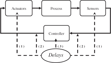
Delays appear naturally in the modeling of several physical processes. In general, the delays come from transportation of materials or the transmission of information. Stability analysis of time-delay systems is thus an important topic in many disciplines of science and engineering [GU 03; NIC 01; RIC 03]. Motivating applications are found in diverse areas, such as biology, chemistry, telecommunication control engineering, economics, and population dynamics [KOL 99a]. There has been an increased interest in the area of time-delay systems over the last two decades due to the emerging area of networked embedded systems, which are systems where sensor and actuator devices communicate with control nodes over a communication network. In such systems, processing time and pre-emption in the network nodes, together with propagation delays in the inter-node communication, necessarily leads to time delays affecting the overall closed-loop control system. Various phenomena related to delays in networked controlled systems have recently been considered, e.g. packet losses [HES 07; NAG 08] and robust sampling [FRI 04b]. The locations where delays appear in a control loop are summarized in Figure 2.2.
1) The actuators and the sensors are generally subsystems which have their own dynamics. A first source of delay is the time taken to achieve the computation of the control algorithm itself. This duration is directly related to the algorithm complexity and to the hardware capabilities. It is known that evaluating the WCET of a given program is a very long (and anyway imprecise) duty, especially with modern processors using caches and pipelines [DEV 05]. Even for quite simple algorithms using a constant number of statements this duration is usually not constant, due to jitter coming from the hardware architecture and from the operating system’s overheads. Moreover many algorithms used in engineering applications and involved in control loops have a variable complexity, depending on input data and operating conditions. This is, for instance, the case in video processing where the computational complexity may strongly vary according to the observed scene, e.g. the number of basic visual features to be extracted and processed. Other algorithms, such as in optimization, have a variable and badly known rate of convergence, so that the number of iterations needed to reach a predefined accuracy may vary considerably. A second source of delays comes from the operating system and scheduling policies. In a complex control system several computing activities share the computing resources under control of a real-time scheduler. Tasks are scheduled according to their importance and/or urgency, stated by their priority. Static schedulers are quite predictable but lead to inflexible implementations. A more flexible and adaptive sharing of computing resources is provided by dynamic and pre-emptive schedulers, where high-priority tasks can pre-empt lower priority ones. However, the complexity of real-life control systems, e.g. where computing activities are triggered by data dependences or asynchronous events, lead to very complex scheduling patterns and increase even more the complexity and unreliability of precise timing analysis of the real-time control system, e.g. [WIT 01].
To avoid increasing the complexity in the model, it is possible to gather computation and pre-emption induced latencies in a single delay in the forward control path. Note that in a well-designed control implementation this “local” delay is usually smaller or equal to the control interval. However, it is not measurable or known when the computation begins, thus it can be handled by the control algorithm only by estimations of its lower and upper bounds.
2) In a basic control loop, data is exchanged from one entity to another (for instance, from the controller to actuator or from the sensors to the controller). Depending on the system this communication might not be instantaneous. The latency between the time a data is sent and the time it is received increase considerably when the controller and the process are remotely installed. This is particularly the case in the so-called networked control systems (NCS) where the communication is achieved through a communication network. Such systems are attracting a lot of attention nowadays. The main problem and interest, at least for the field of time-delay systems, is that the delays become time varying with a high amplitude. Depending on the communication link (wire or wireless communication) and on the communication protocol (TCP, UDP, ZIGBEE, etc.), the quality of the communication can be very low so that exchange data can be lost during their transfer and leads to additional delays. This constitutes a large scale of problems which are exposed in [HES 07; ZAM 08]
In order to cope with the problems connected to delays, one has to understand the difficulties and the complexity that arrive together with delays. In the sequel, a first section briefly points out basic problems which appear when it comes to time-delay systems. This presentation is based on a very simple example. A second section presents the model of delay functions that are usually used in the literature. More especially it will present the usual assumptions that are required to design stability conditions. Finally, the last section exposes the two extensions of the Lyapunov theory to deal with the stability analysis of time-delay systems based on time-domain methods.
2.2.2. What happens when delays appear?
This section introduces the problem of time-delay systems in terms of mathematical considerations. More particularly, this section exposes some reasons for which researchers are still investigating some the topic. To have a better understanding and reading of this section, simple examples are now studied. Consider the following simple example. Through this example, several aspects of time-delay systems are presented. This helps the reader to have a practical approach to understand the relevant point. Let ![]() be a variable whose evolution is governed by
be a variable whose evolution is governed by
where τ > 0 represents the constant delay. If one considers the non-delay case, i.e. τ = 0, it is well known that the solutions of the system are stable and are of the form ![]() . In the following, particular aspects of this equation with delay will allow us to point out the major difficulties of time delay systems and the difference between the non-delay case.
. In the following, particular aspects of this equation with delay will allow us to point out the major difficulties of time delay systems and the difference between the non-delay case.
2.2.2.1. Initial conditions
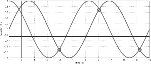
Consider the case where τ = −π/2. The two functions x1(t) = sin(t) and x2(t) = cos(t) are trivial solutions of 2.1. The solutions are shown in Figure 2.3.
In this figure we can find a contradiction with the Cauchy theorem. In the non-delay case, if two solutions of the same linear differential equation cross, then the two solutions are the same. In this simple example, it is clear that the two solutions x1 and x2 cross an infinite number of times but are, by definition not equal. This problem comes from the fact that the state of a time-delay system is not only a vector considered at an instant t as non-delay case is not, but is a function taken over an interval (or a window) of the form [t − τ, t]. Consequently, it is not sufficient to initialize the state of the system by only including the initial position of the state at time t0. It is required to define a vector function ϕ: [t0 − τ, t0] → R such that x(θ) = ϕ(θ) for all θ lying in the delay interval [t0 − τ, t0].
Note that the Cauchy theorem still holds. It is rewritten as follows: if two solutions are equal over an interval of length τ, then the solutions are equal over the whole simulation time.
2.2.2.2. Infinite dimensional systems
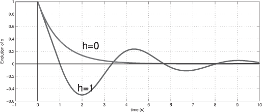
Consider τ = 1 and the initial conditions ϕ(θ) = 1, for all θ in [t0 − τ, t0]. The solutions are shown in Figure 2.4.
As expected, in the non-delay case, the solution is an exponential decreasing function. In the delay case, the solution is not of this form anymore. First the solution has an oscillatory behavior around 0. These oscillations are the usual and expected effect of the introduction of delay in a system. For small values of the delay, these oscillations can be of of very low amplitude and thus negligible. However, for greater values of τ (for instance τ = 2), the oscillations have a larger amplitude and the solution is unstable.
Considering τ = 1 and the same initial conditions, it is possible to construct the solution of the system by integrating interval by interval:

Thus, the solution of the system is a polynomial function whose degree increases with time. One can then see the time-delay system as an infinite dimensional system since its solution is a polynomial of infinite dimension.
Another property of time-delay systems to understand this type of systems is of infinite dimension, is to consider the Laplace transform of equation 2.1. The characteristic equation is
![]()
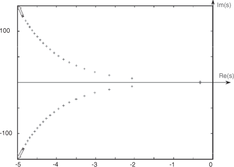
This characteristic equation has an infinite number of complex solutions as shown in Figure 2.5. It is clear that this also implies that a time-delay system is of infinite dimension.
Remark. The stability conditions from roots still holds, i.e. the stability is ensured if the roots of the characteristic equation have a negative real part (see [GU 03] or [NIC 01] for more detailed explanations).
2.2.3. Delay models
In this section, a brief overview of the delay functions is provided in the current literature has been given.
a) Constant delays: The first studies about the stability of time-delay systems mainly concerned this type of delays together with linear time-invariant systems. A lot of stability criteria were developed by on frequency approach [DAM 94], LMI [GU 03], [NIC 01]. They variously deal with known or unknown, bounded and unbounded delays. Since the middle of the 1990’s, several conditions were also expressed in terms of linear matrix inequalities and were able to deal with more complex problems such as linear systems with norm-bounded uncertainties (see [KOL 99b], [LI 97] and [NIC 01]).
b) Bounded time-varying delays: The choice of constant time-delay restriction becomes less relevant when it comes to practical problems as NCS where the delays are induced by networked type of communications [LOP 06; HES 07; ZAM 08] or as in a more practical fluid transportation pipe [ANT 07], to give just two examples. The case of (known or unknown) variable delays have also been the topic of numerous researchers ([RIC 03; KAO 07] and the reference there in). In such a case, the delays appear as a positive scalar functions of the time or of the state of the process. A first type of conditions on the functions is to consider that the delay is bounded, i.e. there exists a positive and known scalar τ2 > 0 such that [HAL 97]
![]()
c) Interval time-varying delays or non-small delays: A large majority of the existing results on time-varying delays only deal with delays functions which vary between 0 and an upper bound. However, in transportation problem or in networked control systems, the delay functions only vary in an interval excluding zero. The case of considering a delay which is sporadically equal to 0 indeed means that, for instance, the transport of a fluid or of information is done instantaneously, which is not relevant in practice. Thus, consider that delay functions which can only vary in a non-zero interval are relevant. One can define the conditions on this type of time-varying delays as follows. There exist two scalars 0 < τ1 < τ2 so that
![]()
Only recent articles deal with this problem [FRI 04a; JIA 05].
d) Delays with constraints on their first derivative: Numerous stability conditions require that the delay functions can vary arbitrarily. The following constraints is often included. Consider a positive scalar d so that
More specifically, the conditions require the constraint that d is strictly less than 1. To understand this condition, consider the function f(t) = t − τ(t) which corresponds to the delayed value considered at time t. The condition d < 1, means that this function is strictly increasing. This can be interpreted as the fact that the transport of the fluid or the delayed information is considered in chronological order.
e) Piece-wise time-varying delays: In practice and more especially in networked control systems, the delay function is not a continuous function. Consider, for instance, the case of sampling over communication networks. Sampling a signal as an increasing sequence of time {tk}k can be seen as a delayed signal with the delay τ(t) = t − tk (see [FRI 04b],[NAG 08] and the reference therein). These cases are very interesting and relevant because of the scientific and practical aspects. The main difficulty comes from the fact that the delay function is discontinuous at the sampling instant and from the fact that the delay derivative is equal to 1 almost all the time, which is critical regarding condition (2.2).
In general, the stability conditions that we can find in the literature included a combination of the previous constraints. More importantly and more interestingly, the stability of the system strongly depends on the type of delay function which is considered. For instance, the stability a system characterized by given constant delay τ2, an unknown time-varying delay bounded by τ2 or a sampling delay (with a constant sampling period) are different (see for instance article [NAG 08; RIC 03] and the references therein). Thus investigating in more accurate tools to cope with each of the previous type of delays is still an active topic and even if time-delay systems have already been paid a lot of attention, there are still a large number of open problems which need to be solved.
2.2.4. Stability analysis of TDS using Lyapunov theory
This section gives a reminder of the theoretical background on the stability analysis of time-delay systems, based only on a time-domain approach and the second method of Lyapunov.
2.2.4.1. The second method
Consider the following time-delay system:
It is assumed that this system has a unique solution and a steady state xt = 0 (is the steady state is non-zero, a change of coordinate can allow it).
The second method of Lyapunov is based on the existence of a function V of the state xt which is positive definite so that its derivative along the trajectories of (2.3), ![]() is definite negative, if xt ≠ 0. This “direct” method is only valid for a reduced class of time-delay systems since the derivative function
is definite negative, if xt ≠ 0. This “direct” method is only valid for a reduced class of time-delay systems since the derivative function ![]() depends on past values of x (included in xt). It is thus restrictive and sometimes complex to cope with time-delay systems. However, two extensions of the second method of Lyapunov have been provided especially for the case of functional differential equations. In the case of ordinary differential equations (i.e. without delays), a candidate for a Lyapunov function is of the form V = V(t, x(t)). It only depends on the current “position”, the current state of the system. In the retarded case, this function is not sufficient to analyze the stability since it does not contain the full state of the system, i.e. the current “position” and also past values of it. The stability analysis requires more assumption on the Lyapunov functions.
depends on past values of x (included in xt). It is thus restrictive and sometimes complex to cope with time-delay systems. However, two extensions of the second method of Lyapunov have been provided especially for the case of functional differential equations. In the case of ordinary differential equations (i.e. without delays), a candidate for a Lyapunov function is of the form V = V(t, x(t)). It only depends on the current “position”, the current state of the system. In the retarded case, this function is not sufficient to analyze the stability since it does not contain the full state of the system, i.e. the current “position” and also past values of it. The stability analysis requires more assumption on the Lyapunov functions.
Two approaches have been provided to cope with functional differential equations: The first one, called the Lyapunov–Razumikhin approach, is based on the same type of Lyapunov function V = V(t, x(t)) but leads to difficulties since the derivative also depends on past values of x. The second one, named the Lyapunov-Krasovskii approach, is based on a functional, and not a function, of the form V = V(t, xt) also leads to several difficulties since it depends on the state xt of the time-delay system. These two approaches are briefly introduced in the sequel.
2.2.4.2. The Lyapunov–Razumikhin approach
Consider a Lyapunov function of the form V(t, x(t)) which only requires to consider vector in ![]() as in the ordinary case. However, the following theorem shows that it only requires that the derivative of V(t, x(t)) ≤ 0 along the trajectories of the system to decrease over the delay interval, i.e. for all
as in the ordinary case. However, the following theorem shows that it only requires that the derivative of V(t, x(t)) ≤ 0 along the trajectories of the system to decrease over the delay interval, i.e. for all ![]() . This test can be restricted to the solutions which tend to leave a close set of the form V(t, x(t)) ≤ c around the equilibrium.
. This test can be restricted to the solutions which tend to leave a close set of the form V(t, x(t)) ≤ c around the equilibrium.
THEOREM.–[[KOL 99a]] Consider increasing functions u, v and w: ![]() so that u(θ) and v(θ) are strictly positive for all θ > 0. Assume that the vector field f of (2.3) is bounded for bounded values of its arguments. Then if there exists a continuous function V:
so that u(θ) and v(θ) are strictly positive for all θ > 0. Assume that the vector field f of (2.3) is bounded for bounded values of its arguments. Then if there exists a continuous function V: ![]() such that
such that
– ![]() ,
,
– ![]() for all trajectories of (2.3) satisfying:
for all trajectories of (2.3) satisfying:
then the solution xt = 0 of (2.3) is uniformly stable.
Moreover, if w(θ) > 0 for all θ > 0 and if there exists a strictly increasing function ![]() satisfying p(θ) > θ for all θ > 0 so that
satisfying p(θ) > θ for all θ > 0 so that
– ![]() ,
,
– ![]() , for all trajectories of (2.3) satisfying:
, for all trajectories of (2.3) satisfying:
then V is called the Lyapunov–Razumikhin function and the solution xt = 0 of (2.3) is uniformly asymptotically stable.
Remark. In practice, the more common functions p are of the form p = qθ where q is a constant strictly greater than 1 and the Lyapunov–Razumikhin functions to design are generally chosen as simple quadratic functions of the form V(t) = xT (t) Px (t) where P is a positive definite matrix. Condition (2.5) thus becomes
![]()
Note that it was proved, in [DRI 77], that the two approaches are equivalent in the case of constant delays. In the time-varying delay case, the Lyapunov–Razumikhin approach has the particularity to easily take into account variable delay without considering additional constraints on the derivative of the delay function of the type (2.2). However, in such a situation, it leads to more conservative stability conditions than the Lyapunov–Krasovskii approach described in what follows.
2.2.4.3. The Lyapunov–Krasovskii approach
This method is an extension of the Lyapunov theorem to the case of functional differential equations. It consists of the research of afunctional of the form ![]() which decreases along the trajectories of (2.3). Similarly, V is called a functional because it depends on the state of the time-delay system xt which a vector function considers the delay interval [t − τ, τ].
which decreases along the trajectories of (2.3). Similarly, V is called a functional because it depends on the state of the time-delay system xt which a vector function considers the delay interval [t − τ, τ].
THEOREM.–[[KOL 99a]] Consider continuous and increasing functions u, υ, w: ![]() so that u(θ) and υ(θ) are strictly positive for all θ > 0 and u(0) = υ(0) = 0. Assume that the vector field f of (2.3) is bounded for bounded values of its arguments. Then if there exists afunctional
so that u(θ) and υ(θ) are strictly positive for all θ > 0 and u(0) = υ(0) = 0. Assume that the vector field f of (2.3) is bounded for bounded values of its arguments. Then if there exists afunctional ![]() so that
so that
– ![]() ,
,
– ![]() for all t ≥ t0 along the trajectories of (2.3),
for all t ≥ t0 along the trajectories of (2.3),
then the solution xt = 0 of (2.3) is uniformly stable. Moreover if w(θ) > 0 for all θ > 0, then the solution xt is uniformly asymptotically stable.
If ![]() satisfies the following conditions:
satisfies the following conditions:
– ![]() ,
,
– ![]() , for t ≥ t0 and w(θ) > 0 for all θ > 0,
, for t ≥ t0 and w(θ) > 0 for all θ > 0,
– ![]() is Lipschitz with respect to its second argument,
is Lipschitz with respect to its second argument,
Then the solution xt of (2.3) is exponentially stable and the functional ![]() is called Lyapunov-Krasovskii functional.
is called Lyapunov-Krasovskii functional.
Remark. In the previous theorem, the notation ![]() refers to the derivative in the sense of Dini, i.e.
refers to the derivative in the sense of Dini, i.e. ![]() .
.
The main idea of the theorem is to determine a positive definite functional ![]() whose derivative along the trajectories of (2.3) is negative definite. Of course the main difficulties come from the design of such a functional if it exists. The classical type of functionals are of the following form ([KOL 96], section 2.2.2):
whose derivative along the trajectories of (2.3) is negative definite. Of course the main difficulties come from the design of such a functional if it exists. The classical type of functionals are of the following form ([KOL 96], section 2.2.2):
![]()
where P, Q, R, and S are square matrix functions of dimension n×n. P(t) and S(ζ) are symmetric positive definite and R satisfies R(t, σ, ρ) = RT (t, ρ, σ). It is assumed that each element of these matrices are bounded and their derivatives are piece-wise continuous functions.
In practice, the research of such functionals leads to complex problems to solve. Often, researchers limit themselves to the cases where the matrix functions P, Q, R, and S are constant. In such a situation, the previous Lyapunov–Krasovskii functional becomes:
![]()
This type of Lyapunov–Krasovskii function leads to the positive property that it proves the stability only for the delay τ and not lower values of the delay. This is positive for some systems where the delay has a stabilizing effect (see for instance [SEU 09c; MIC 04; GU 97]). However, it is possible to design another type Lyapunov–Krasovskii functionals which allows stability to be assured for constant or time-varying bounded delays. This is done by considering another integral functional expressed with the derivative of the state ![]() of the form
of the form
![]()
However, we have to be careful with the use of this functional since it might introduce some additional dynamics or constraints, since the functional now depends on the derivative ![]() and not ϕ itself (see [GU 03] and [NIC 01] for more details).
and not ϕ itself (see [GU 03] and [NIC 01] for more details).
Note that recent stability conditions have been established using matrix functions for the parameters Q, R, and S. The discretization method introduced in [GU 97; GU 03], allows us to construct piece-wise linear functions as the matrix parameters by dividing the delay interval into several smaller intervals on which the parameters of the functionals are linearly varying. The stability analysis leads to less conservative conditions than in the case of constant parameters but extensions to the time-varying delay case are not straightforward. In [PAP 07], a method to build functionals with varying parameters based on the sum of squares tools is introduced. Another recent approach method is based on Integral Quadratic Constraints [KAO 07]. It provides a new interpretation of the Lyapunov–Krasovskii functionals and the potential conservatism (see [ARI 07]). Another method has been provided based on the solutions of an arbitrary differential equations to build exponential [SEU 09b] and polynomial [SEU 09a] parameters.
Remark. One has to understand that those two theorems only lead to sufficient conditions of stability. In [KHA 01], a complete Lyapunov–Krasovskii functional (i.e. which corresponds to necessary and sufficient conditions of stability) is constructed by solving a functional differential equation. This approach is useful to derive robustness conditions with respect to delay variations [FRI 08a] or parameter uncertainties [KOL 03], [MON 05].
In general, the two previous theorems applied to the case of linear systems with delay is expressed in terms of linear matrix inequalities. Based on semi-definite programming (see [BOY 94; GHA 00]), it becomes easy to find solutions of this type of problems using for instance the LMI Toolbox from Matlab (http://www.mathworks.com) or Scilab (http://www.scilab.org). These two approaches are not only reduced to cope with the stability of time-delay systems. These methods have been extended to numerous problems such as stability and stabilization of linear parameter-varying (LPV) systems (see [BRI 08], section 2.4 and the references therein), H∞ control (for instance [FRI 02; LI 97]), stabilization finite time [MOU 06], input-to-output or input-to-state stability ([FRI 08b],[GU 03]).
2.2.5. Summary: time-delay systems and networking
This section proposed a brief overview on the problems which appear in the context of time-delay systems. Even if delay requires careful attention, there already exist a large number of stability conditions including robustness issues with respect to the parameter uncertainties and delay variations. Networked control systems are characterized by a complex interaction between heterogenous components and timing incertitudes. It is unlikely that the values of computing, scheduling and networking latencies can be accurately modeled and predicted, therefore robust control approaches are particularly attractive and convincing to cope with the various sources of induced latencies in networked control systems, as it is easier (and real-time cheaper) to evaluate an upper bound of aggregated delays rather than an actual measurement or accurate prediction. Note that, even if being of old concern, research on time-delay systems is still a very active field where many recent results are of prime interest in NCS.
2.3. Weakly hard constraints
In this section, a particular model of uncertainty is addressed. This uncertainty is rather related to the ability or the inability of the control task to update the control, at given instances, which are known at (control and real-time scheduling) design time. This uncertainty model may originate from the application of the weekly-hard realtime framework [BER 01]. There are two main motivations behind the application of this framework as follows:
– The need to minimize computational resource economic costs, which is a strong requirement in the development process of embedded systems, especially in the context of their mass production. In real applications, and due to task execution time variations, there is an important gap between average-case and worst-case processor utilization. Due to this gap, the application of state-of-the-art worst-case design methodology leads to an over-dimensioning of the required resources and consequently to their under-utilization. The reduction of computational resources cost may be achieved if methods allowing the needed resources to be dimensioned according to average utilization needs, and not to worst-case utilization scenarios, are employed. In both cases, achieving the stability and ensuring a minimum performance level are required.
– The need to define application-level-degraded modes in distributed control systems. These degraded modes may be activated, for example, in the case of a processor failure. In order to ensure a graceful degradation of the application performance, and to avoid a sudden breakdown of the whole system, the application has to continue running in a degraded mode, where all the tasks of faulty processors are dispatched into the other running processors. This may cause an overload situation.
The framework of weakly hard real-time scheduling was introduced in [BER 01]. This framework encapsulates many previously introduced task models and schedu-lability constraints such as (m, k)-firm [RAM 95] and skipover [KOR 95]. It allows handling tasks that can tolerate a clearly specified number of missed deadlines during a window of time. For those reasons, this framework appears to be a suitable approach allowing the design and implementation of control tasks based on their average execution times. In order to exploit this framework in a rigorous way, appropriate control design approaches have to be proposed. The design of such strategies was addressed in [BEN 08], and will be summarized throughout this section.
Although the weakly hard real-time scheduling paradigm received significant interest, few works were dedicated to the problem of the control design under weakly hard scheduling constraints. [RAM 99] proposed the use of the (m, k)-firm scheduling concept to achieve a graceful degradation in a situation of processor overload. In this approach, the different jobs of a control task are classified into mandatory and optional. Mandatory jobs are guaranteed to be completed before their deadlines. Optional jobs may either meet or miss their deadlines. The proposed associated control design methodology, which relies on the optimal linear quadratic periodic control theory, modifies the gains of the mandatory jobs in order to minimize the degradation which may result from executing the original control law in an overloaded processor. However, no control design methodology was proposed to compute the control law of the optional jobs (which simply maintain the previous controls constant). For this reason, this design method does not allow the successful executions of the optional instances to be exploited.
This section describes a control design method allowing the advantages of the weakly hard real-time scheduling concept to be exploited. It first provides a summary and then extends the contributions of [BEN 08].
2.3.1. Problem definition
Consider the control system described by the following difference equation:
For any discrete instants ka and kb such that ka ≤ kb, notation u(ka, kb) represents the control input sequence (u(ka),…, u(kb)).
A cost functional J is associated with system (2.6), and is defined by
It is assumed that q is chosen to ensure that when J(x(0),u(0, ∞)) is finite, then the controlled system (2.6) is uniformly asymptotically stable. J(x(ka),u(ka,kb)) denotes the cost function corresponding to an evolution starting from state x(ka) at instant ka to instant kb, and where the control sequence u(ka, kb) is applied.
System (2.6) is controlled by a periodic control task τ, whose execution period is assigned according to average utilization considerations. To simplify the discussions, it is assumed that this period is identical to the time period separating two consecutive discrete instants. However, due to the variations of its own execution time (up to its Worst Case Execution Time, or WCET), and also to the variations of the processor load, the jobs of task τ are not ensured to be completed by their deadlines; the deadline of a job is defined as the release time of its subsequent job. Therefore, in order to characterize the jobs that complete by their deadlines, and the others that will miss their deadlines, and will be consequently aborted, the notion of execution sequence is introduced.
DEFINITION.– An execution sequence σ is an infinite sequence of elements of {0,1}.
According to this definition, execution sequences are elements of ![]() . An execution sequence σ is associated with each completion of task τ, and defined by
. An execution sequence σ is associated with each completion of task τ, and defined by

Let ![]() be the set valued function that associates to each execution sequence the invocation count (i.e. the discrete instant of activation) of the jobs that are finished before their deadlines. Formally,
be the set valued function that associates to each execution sequence the invocation count (i.e. the discrete instant of activation) of the jobs that are finished before their deadlines. Formally, ![]() is defined by
is defined by
![]()
Fortunately, using a priority-based scheduling, and knowing the WCET of all the tasks that have priority over τ, it is possible to guarantee that selected jobs of τ will always meet their deadlines. This may be ensured using weakly hard schedulability analysis techniques developed in [RAM 99] and [BER 01]. In the following, it is assumed that task τ guarantees a (μ, κ )-constraint where μ and κ are two integers so that μ ≤ κ (i.e. the deadlines of μ out of any κ consecutive jobs of τ are met). It is also assumed that this constraint is met by guaranteeing that the jobs whose invocation count κ verifies
will always meet their deadlines. These jobs are called mandatory jobs. The other jobs, which are not guaranteed to be completed by their deadlines, are called optional jobs. It has been proved in [RAM 99] that when the jobs of a given task are classified according to (2.8), then the pattern of mandatory jobs will be κ-periodic. This means that if the job activated at instant k is mandatory, than any job activated at instant ![]() is also mandatory. Consequently, when only these mandatory jobs are guaranteed to be completed before their deadlines, the worst-case execution sequence γ that may be associated with τ is defined by
is also mandatory. Consequently, when only these mandatory jobs are guaranteed to be completed before their deadlines, the worst-case execution sequence γ that may be associated with τ is defined by
When relation (2.8) is applied to impose the worst-case execution pattern of task τ, the corresponding worst-case execution sequence γ is guaranteed to be a κ-periodic execution sequence, verifying γ(k) = γ(k + κ).
2.3.2. Notion of accelerable control
For any given control law ξ(k) defined over ![]() denotes the control input to the plant, taking into account execution constraints. Therefore, ξσ(k) is defined by
denotes the control input to the plant, taking into account execution constraints. Therefore, ξσ(k) is defined by
![]()
Now the notion of accelerable control can be introduced.
DEFINITION.– [BEN 08] Assume that a control law ξ(k) was defined, so that for all ![]() , the cost function J(x0,ξγ(0, ∞)) corresponding to the worst-case execution sequence γ is finite. The control law ξ(k) is called accelerable according to performance index (2.7) and worst-case execution sequence γ, if for all execution sequences σ1 and σ2 so that
, the cost function J(x0,ξγ(0, ∞)) corresponding to the worst-case execution sequence γ is finite. The control law ξ(k) is called accelerable according to performance index (2.7) and worst-case execution sequence γ, if for all execution sequences σ1 and σ2 so that ![]() , for all
, for all ![]() , the associated cost functions satisfy J(x0, ξσ1 (0, ∞)) ≤ J(x0, ξσ2 (0, ∞)).
, the associated cost functions satisfy J(x0, ξσ1 (0, ∞)) ≤ J(x0, ξσ2 (0, ∞)).
A control task executing an accelerable control law will be called accelerable control task. An accelerable control task has the property that the more executions are performed, the better the control performance. When used in conjunction with weakly hard real-time scheduling design, an accelerable control task allows us to take advantage of the extra computational resources that may be allocated to it (the successful execution of optional task instances), and to improve the control performance with respect to worst-case design methods. In practice, however, control laws designed using standard sampled-data control design methods are not necessarily accelerable. This fact was demonstrated in [BEN 08].
2.3.3. Design of accelerable controllers
Let σ be an execution sequence and ![]() a time instant.
a time instant. ![]() denotes the execution sequence defined by
denotes the execution sequence defined by
![]()
In the following, a general method for constructing accelerable control laws is presented. Let γ be a worst-case execution sequence determined according to (2.8). Let ka and kb two discrete instants such that ka ≤ kb. Let ![]() be the set of admissible control inputs, defined between instants ka and kb, taking into account the resource constraints that are modeled by the execution sequence ρ. The set
be the set of admissible control inputs, defined between instants ka and kb, taking into account the resource constraints that are modeled by the execution sequence ρ. The set ![]() is formally defined as {u(ka, kb), so that u(k) = u(k − 1) if ρ(k) = 0}.
is formally defined as {u(ka, kb), so that u(k) = u(k − 1) if ρ(k) = 0}.
In the rest, the following assumption are made.
ASSUMPTION.– For all ![]() and
and ![]() ,
,
![]()
For any given ![]() and
and ![]() , an optimal control sequence corresponding to an evolution over an infinite horizon, starting at instant k from state x(k), and taking into account the computation constraints defined by the execution sequence
, an optimal control sequence corresponding to an evolution over an infinite horizon, starting at instant k from state x(k), and taking into account the computation constraints defined by the execution sequence ![]() , will be denoted as
, will be denoted as
An optimal solution of problem (2.10) is a control sequence ![]() that minimizes the cost function J, corresponding to an evolution over an infinite horizon, starting from state x(k) at instant k, and assuming that
that minimizes the cost function J, corresponding to an evolution over an infinite horizon, starting from state x(k) at instant k, and assuming that
– the job (mandatory or optional) activated at instant k will meet its deadline and update the plant,
– the subsequent computation constraints (from instant k + 1 to ∞) are described following the worst-case execution sequence.
Based on the solutions of optimization problems (2.10), it is possible to construct, in a simple way, an accelerable control law. Let ![]() be the first element of the optimal control sequence
be the first element of the optimal control sequence ![]() :
:
Strategy ![]() may be seen as a “robust control” approach against execution uncertainties satisfying the introduced weakly hard model. It allows us to be minimized the cost function J for the “worst-case uncertainty” from the implementation. Under the Assumption in section 2.3.3, strategy (2.11) provides a general method for constructing accelerable control laws. The following theorem, borrowed form [BEN 08], states the accelerability properties of strategy (2.11).
may be seen as a “robust control” approach against execution uncertainties satisfying the introduced weakly hard model. It allows us to be minimized the cost function J for the “worst-case uncertainty” from the implementation. Under the Assumption in section 2.3.3, strategy (2.11) provides a general method for constructing accelerable control laws. The following theorem, borrowed form [BEN 08], states the accelerability properties of strategy (2.11).
THEOREM.– Let γ be a worst-case execution sequence. Under Assumption 2.3.3, control law ![]() , as defined in (2.11), is accelerable in accordance to (2.7) and γ.
, as defined in (2.11), is accelerable in accordance to (2.7) and γ.
2.3.4. Accelerable LQR design for LTI systems
In this subsection, only Linear Time Invariant (LTI) plants are considered. Under the Assumption in section 2.3.3, which will be met if reachability properties (as defined for linear time-varying systems) are fulfilled and when the cost functions are appropriately chosen, it becomes possible to compute off-line a closed form of ![]() , which will be a time-varying state feedback. In the rest of this section, the following assumption is made.
, which will be a time-varying state feedback. In the rest of this section, the following assumption is made.
ASSUMPTION.–

where ![]() .
.
In the following, the methodology underlying the design of the accelerable control law ![]() is developed. The following definitions are first introduced. Let γ be a worst-case execution sequence defined according to (2.9). The application of the theorem in section 2.3.3 to LTI systems is described by the following corollary.
is developed. The following definitions are first introduced. Let γ be a worst-case execution sequence defined according to (2.9). The application of the theorem in section 2.3.3 to LTI systems is described by the following corollary.
COROLLARY.– [[BEN 08]] Let γ be a worst-case execution sequence defined according to (2.9). Under the assumptions in sections 2.3.3 and 2.3.4, the state feedback control law defined by
is accelerable in accordance to (2.7) and γ, where
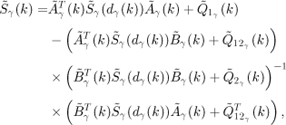
Matrices ![]() are defined for as the steady state solutions of the following Riccati equation
are defined for as the steady state solutions of the following Riccati equation
where
and ![]() is partitioned as
is partitioned as
![]()
2.3.5. Kalman filtering and accelerability
Consider the following linear discrete-time system
where ![]() is the output,
is the output, ![]() and
and ![]() are Gaussian random vectors with zero mean and respective co-variance matrices W ≥; 0 and V > 0. The pair (A, W) is supposed stabilizable and that the pair (A, C) is detectable. w(k) is independent of w(l) for l < k. The initial state is assumed to be a Gaussian random vector with zero mean and co-variance X0. To simplify the further developments, υ and ω are assumed mutually independent.
are Gaussian random vectors with zero mean and respective co-variance matrices W ≥; 0 and V > 0. The pair (A, W) is supposed stabilizable and that the pair (A, C) is detectable. w(k) is independent of w(l) for l < k. The initial state is assumed to be a Gaussian random vector with zero mean and co-variance X0. To simplify the further developments, υ and ω are assumed mutually independent.
The control task τ has to determine an estimate of the state of system (2.3.5), which minimizes the co-variance of the a posteriori estimation error, and under the computation constraints defined by a given execution sequence σ (which is unknown at design time). The a priori and the a posteriori estimates of state x(k) are respectively denoted by ![]() and
and ![]() . Matrices P(k|k− 1) and P(k|k) will denote respectively the co-variance matrices of the a priori (i.e
. Matrices P(k|k− 1) and P(k|k) will denote respectively the co-variance matrices of the a priori (i.e ![]() ) and the a posteriori (i.e
) and the a posteriori (i.e ![]() ) estimation errors. Let yk = [y(0),…, y(k)] and
) estimation errors. Let yk = [y(0),…, y(k)] and ![]() and P(k|k) are defined by the following equations
and P(k|k) are defined by the following equations
The computational constraints, which prevent task τ from computing an estimate of the state at instants k where σ(k) = 0 may be modeled using the approach of [SIN 04]. In this approach, the output noise model is modified so that
In [SIN 04], it has been shown that the equations of the Kalman filter with intermittent observations are defined as follows.
In particular, the iterations of the co-variance matrices ![]() and
and ![]() are defined by
are defined by
and
These last equations show that the Kalman filter is accelerable. In fact, the terms
![]()
and
![]()
are definite positive (because V > 0 and ![]() ). Consequently, when σ(k) = 1, the co-variance matrices values
). Consequently, when σ(k) = 1, the co-variance matrices values ![]() and
and ![]() (which represent the quality of the state estimation) will be better than respectively
(which represent the quality of the state estimation) will be better than respectively ![]() and
and ![]() (which represent their respective values if σ(k) = 0). This shows the intrinsic accelerability properties of the Kalman filter (2.3.5).
(which represent their respective values if σ(k) = 0). This shows the intrinsic accelerability properties of the Kalman filter (2.3.5).
2.3.6. Robustifying feedback scheduling using weakly hard scheduling concepts
Feedback scheduling is a control theoretical approach to real-time scheduling of systems with variable workload. The feedback scheduler may be seen as a “scheduling controller” that receives filtered measures of tasks execution times and acts on tasks periods in order to optimize a quality of control criterion. In practice, the feedback scheduler is implemented as a particular real-time task, which is triggered periodically (at a period which is sufficiently greater than other task periods), in order to adjust control tasks periods according to their average execution time estimates, while optimizing a control performance criterion. However, when achieving high processor utilization rates is desired, these basic implementations of feedback scheduling algorithms do not provide any guarantees on the number of deadline misses, input output latencies and effective sampling periods that control tasks may experience during the sampling period of the feedback scheduler. In fact, between two consecutive executions of the feedback scheduler, the execution time of each task may vary in a random fashion up to a maximal value. There may exist some situations when the execution times of some tasks exceed their estimated average value. Consequently, the effective CPU utilization may also exceed the estimated average CPU utilization, according to which task periods were adjusted. In this overload situation, lower priority tasks may experience several deadline misses, long input output latency and effective sampling period, leading to a severe degradation of the control performance. This problem is illustrated by the following example.
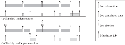
EXAMPLE.– Consider two control tasks τ1 and τ2. The execution times of these tasks vary respectively between [1, 3] and [0.5, 1.5]. Their measured average execution times are, respectively, equal to 2 and 1. The utilization set points for each task are respectively equal to 66% and 25%. Consequently, the assigned periods are, respectively, equal to 3 and 4. Figure 2.6(a) depicts a situation when three consecutive executions of control task τ1 exceed their average estimated execution time. In this situation, the second task experiences an input output latency of about three consecutive sampling periods, which may significantly degrade its performance.
Fortunately, using a weakly hard scheduling approach allows dealing with these situations of transient overload. Instead of causing the “starvation” of lower priority tasks, these approaches allow performance to be gradually degraded, when overload occurs, as illustrated in Figure 2.6(b). In this situation, the marking of the jobs of tasks τ1 and τ2 was performed according to the (m, k)-pattern (1,2). This ensures that in the most severe overload condition, no more than two consecutive deadlines of tasks τ1 and τ2 are missed.
2.3.7. Application to the attitude control of a quadrotor
Consider the problem of the attitude control of a quadrotor. A quadrotor is a rotor-craft that is lifted and propelled by four rotors. Chapter 7 provides a detailed description of the used quadrotor model as well as a review of the mathematical concepts used to describe it. The attitude (i.e. orientation) of the quadrotor is completely described using a unitary quaternion ![]() , with
, with ![]() , where q0 and
, where q0 and ![]() are, respectively, the scalar and vector parts of the quaternion. The unit quaternion represents the rotation from an inertial frame to the body frame attached to the quadrotor. The dynamic evolution of the attitude quaternion is given by
are, respectively, the scalar and vector parts of the quaternion. The unit quaternion represents the rotation from an inertial frame to the body frame attached to the quadrotor. The dynamic evolution of the attitude quaternion is given by
where ![]() is the angular velocity of the quadrotor in the body frame and [
is the angular velocity of the quadrotor in the body frame and [![]() ] is the skew symmetric tensor associated with q
] is the skew symmetric tensor associated with q

The rotational motion of the quadrotor, neglecting the gyroscopic torques, is given by
where ![]() is the inertia matrix of the quadrotor with respect to the body frame. If is constant.
is the inertia matrix of the quadrotor with respect to the body frame. If is constant. ![]() represents the torques resulting from the differences of the relative speeds of the four rotors, and may be written as
represents the torques resulting from the differences of the relative speeds of the four rotors, and may be written as

and ![]() describe the aerodynamic disturbances acting on the quadrotor.
describe the aerodynamic disturbances acting on the quadrotor.
The objective of the attitude controller is to drive the quadrotor attitude to a desired value, which is specified by a unitary quaternion. In practice, this attitude may also be specified by Euler angles (ϕ, θ, ψ), which are more intuitive than quaternions.
To design the attitude controller, consider the linearized model of equations (2.33) and (2.34), and where Euler angles are used instead of quaternions for the description of the attitude. This linearized model is described by
with ![]() and uc = τa.
and uc = τa.
The attitude controller acts on τa, based on e and ω. It is assumed that e and ω are measured by an Inertial Measurement Unit (IMU). The attitude controller is implemented as periodic task τ, with period Ts = 50 ms. Let x(k) = xc (kTs). Assume that the estimated WCET of task τ is three times its average execution time. According to the weakly hard scheduling philosophy, a (1,3)-firm constraint is associated with task τ. The corresponding worst-case execution sequence is described by the periodic execution sequence γ = (1,0, 0, 1, 0, 0, …). An accelerable control design, based on the worst-case execution sequence γ was performed (according to corollary 1). In the following simulations, the assigned set point for the attitude controller is ![]() . The accelerable control law
. The accelerable control law ![]() is defined by
is defined by
![]()
where
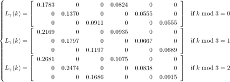
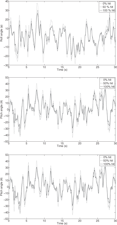
In this particular example, the influence of sampling period reduction manifests itself on different control performance attributes, in particular on the disturbance rejection abilities. Figure 2.7 illustrates this point, and compares the controlled attitude of quadrotor, described by Euler angles (ϕ, θ, ψ), in three different situations as follows.
– The situation where all the optional jobs are not executed (0% hit); this corresponds to the state of the practice hard real-time scheduling design, where resources are dimensioned according to worst-case utilization situations.
– The situation where all optional jobs are triggered for execution (according to the weakly hard real-time scheduling philosophy) and when 50% of them meet their deadlines and update the control, according to a random Bernoulli probability distribution, with success probability 1/2 (50% hit).
– The best-case situation where all the optional jobs are triggered and meet their deadlines (100% hit).
The aerodynamic disturbances τdist(t) are modeled by band-limited white noises, with noise power 10−3 and period 10−1, and which are produced using different seeds. Figure 2.7 shows that significant improvements in control performance result from the weakly hard real-time design, with respect to the worst-case real-time design. The band-limited white noise disturbances are better rejected. These improvements are due to the fact that in the accelerable weakly hard design, optional instances are executed when possible, with conveniently computed and compensated control gains.
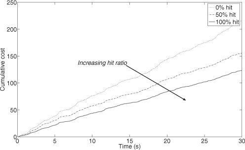
Finally, Figure 2.8 depicts the cumulative cost functions that are associated with the previous simulations. They illustrate the intuitive notion behind accelerability: the more optional instances are executed, the better the control performance. It is worth noticing that although the design was performed on the linearized model, these significant improvements are observed on the nonlinear model. This suggests the robustness of the used control design methodology.
2.4. LPV adaptive variable sampling
As seen in section 1.4, the key actuator to be used for CPU utilization or network bandwidth control is the control interval. A first idea is to design a bank of controllers, each of them being designed and tuned for a specific sampling frequency, and to switch between them according to the decisions of the feedback scheduler. However, it has been observed that switching without caution between such controllers may lead to instability although each controller in isolation is stable [SCH 02].
To ensure the system’s stability for a measured variable input delay, [SAL 05] proposes for example a gain scheduled approach based on time-varying observers and state feedback controllers, synthesized using linear matrix inequalities (LMI) and quadratic Lyapunov functions. Indeed, gain scheduling is a popular approach to control nonlinear plants, allowing to some extent to re-use the well-known linear control theory and tools [LEI 00]. The model of the plant is linearized around a set of operating points, and the control responsibility is switched to the controller whose specification is the closest to the actual operating conditions. LPV approaches were then developed to enforce the overall control system stability during switching.
Based on these tools, this section presents a varying sampling rate control algorithm based on LPV gain scheduling design: the gain scheduled controller is able to guarantee the system’s stability whatever the instants and speed of variation of the control task intervals. A specified performance level must also be preserved in the allowed interval range. However, this approach is up to now only designed for linear systems. The first point is the problem formulation so that it can be solved following the LPV design of [APK 95]. Remember that this design ensures the stability and performance robustness of the closed-loop parameter-varying system whatever the variations of the parameters inside their predefined allowed range.
Here a parameterized discretization of the continuous time plant and of the weighting functions leads to a discrete-time, sampling period-dependent, augmented plant. In particular, the plant discretization approximates the matrix exponentials appearing in the discretized model by a Taylor series of order N. The original LPV design builds a discrete-time sampling period dependent controller through the convex combination of 2N controllers, which may be conservative and complex to implement. In the particular case where the control interval is in only varying parameter, the dependency between the variable parameters, which are the successive powers of the sampling period h, h2, …, hN, is used to reduce the number of controllers to be combined down to N + 1. This reduction of the polytopic set drastically decreases the conservatism of the original design and makes the solution easier to implement. A summary of this approach, which is described in details in [ROB 07a], [ROB 09], and [ROB 07b], is given in the following sections.
2.4.1. A polytopic discrete-plant model
A state space representation of a continuous time plant is
The exact discretization of this system with a zero-order hold at the sampling period h can be computed, e.g. see [ÅST 97], leading to the discrete-time LPV system 2.37
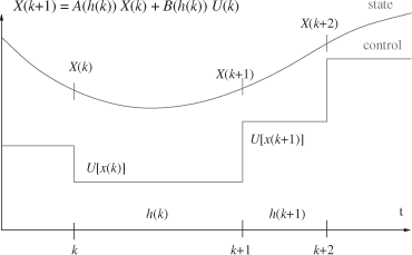
with h ranging in [hmin; hmax]. The corresponding sampling and hold scheme are depicted in Figure 2.9: the control signal U[t(k)] computed at the kth instant from measure X[t(k)] is hold until instant t(k + 1), which is known and given by a controlled scheduler, e.g. by a feedback scheduler as described in section 1.4.2.3 or a (m, k)-firm policy as used in section 5.2.5.
However, computing Ad and Bd involve matrix exponentials of the original A and B matrices and thus are not affine on h. To get a polytopic model and then apply an LPV design, the exponential is approximated by a Taylor series of order N. Since h is assumed to belong to the interval [hmin, hmax] with hmin > 0, the sampling period is approximated around the nominal value h0 of the sampling period, as
It can be written that
where
and
In order to get a polytopic model, a Taylor series of order N is used to approximate the matrix exponential in 2.41, and allows us to get
This leads to
Let us define H = [δ, δ2,…, δN] the vector of parameters that belong to a convex polytope (hyper-polygon) ![]() with 2N vertices.
with 2N vertices.

Each vertex is defined by a vector ![]() , where
, where ![]() can take the extrema values
can take the extrema values ![]() with δmin = hmin − h0 and δmax = hmax − h0.
with δmin = hmin − h0 and δmax = hmax − h0.
The matrices Ad (δ) and Bd (δ) are therefore affine in H and given by the polytopic forms
![]()
where the matrices at the vertices, i.e. ![]() and
and ![]() , are obtained by the calculation of Ad(δ) and Bd(δ) at each vertex of the polytope
, are obtained by the calculation of Ad(δ) and Bd(δ) at each vertex of the polytope ![]() . The polytopic coordinates αi which represent the position of a particular parameter vector H (δ) in the polytope
. The polytopic coordinates αi which represent the position of a particular parameter vector H (δ) in the polytope ![]() are given solving
are given solving
As the gain-scheduled controller will be a convex combination of 2N “vertex” controllers, the choice of the series order N gives a trade-off between the approximation accuracy and the controller complexity.
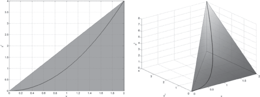
To decrease the volume and number of vertices of the matrice polytope, the dependency between the successive powers of the parameter h is exploited. Remember that the vertices ωi of ![]() are defined by h, h2,…, hN, with
are defined by h, h2,…, hN, with ![]() . Indeed, the representative point of the parameters set is constrained to be on a one-dimensional curve, so that the polytope of interest can be reduced to the “lower” N + 1 vertices, as illustrated in Figure 2.10 for the cases N = 2 and 3.
. Indeed, the representative point of the parameters set is constrained to be on a one-dimensional curve, so that the polytope of interest can be reduced to the “lower” N + 1 vertices, as illustrated in Figure 2.10 for the cases N = 2 and 3.
2.4.2. Performance specification
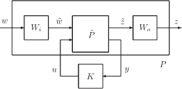
In the H∞ framework, the general control configuration of Figure 2.11 is considered, where Wi and Wo are weighting functions specifying closed-loop performances (see [SKO 96]). The objective here is to find a controller K so that internal stability is achieved and ![]() , where γ represents the H∞ attenuation level.
, where γ represents the H∞ attenuation level.
Classic control design assumes constant performance objectives and produces a controller with a unique sampling period. This sampling period is chosen according to the controller bandwidth, the noise sensitivity and the availability of computation resources. When the sampling period varies, the usable controller bandwidth also varies
and the closed-loop objectives should logically be adapted; therefore, the bandwidth of the weighting functions is adapted. In this aim, Wi and Wo are split into two parts:
– a constant part with constant poles and zeros. This allows, for instance, to compensate for oscillations or flexible modes which are, by definition, independent of the sampling period. This part is merged with the plant before its discretization.
– the variable part contains poles and zeros whose pulsations are expressed as an affine function of the frequency f = 1/h, which allow the bandwidth of the weighting functions to be adapted. These poles and zeros are here constrained to be real by the discretization step. Finally, opportune cancelations make the discretized templates independent of h, facilitating further interconnections.
Indeed, preliminary experiences with varying sampling control [ROB 05] pointed out the advantages of performance adaptation w.r.t. to the sampling rate to preserve stability margins and to keep the control size inside wise bounds.
2.4.3. LPV/H∞ control design
The interconnection between the discrete-time polytopic model of the plant ![]() (now including the constant part of the weighting functions) and the variable weighting functions Wi and Wo leads to the discrete-time LPV-augmented plant P(H) is depicted in Figure 2.11.
(now including the constant part of the weighting functions) and the variable weighting functions Wi and Wo leads to the discrete-time LPV-augmented plant P(H) is depicted in Figure 2.11.
The H∞ control design for linear parameter-varying systems detailed in [APK 95] is used here. The method states that under some mild conditions, there exists a gain-scheduled controller:
where ![]() , ensuring overall parameter trajectories, for the closed-loop system:
, ensuring overall parameter trajectories, for the closed-loop system:
– closed-loop quadratic stability
– ![]() -induced norm of the operator mapping w into z bounded by γ, i.e.
-induced norm of the operator mapping w into z bounded by γ, i.e. ![]() .
.
N + 1 controllers are reconstructed at each vertex of the parameter polytope (corresponding with the extreme values of the parameters). The gain-scheduled controller K(H) is then the convex combination of these controllers
![]()
with αi(h) so that ![]() . Note that on-line scheduling of the controller needs the computation of αi(h) knowing h. Considering a Taylor’s expansion around h0 with
. Note that on-line scheduling of the controller needs the computation of αi(h) knowing h. Considering a Taylor’s expansion around h0 with
![]()
and the case of the reduced polytope, explicit solutions are easily recursively computed using
2.4.4. Experimental assessment
The latter approach has been experimentally assessed using a “T”-inverted pendulum, as extensively described in [ROB 07b].
As such a T-pendulum system is difficult to be controlled, our main objective here is to get a closed-loop stable system, to emphasis the practical feasibility of the proposed methodology for real-time control.
The sampling interval is assumed to be in the interval [1,3] ms. Note that the sampling rate seems to be very fast compared with the closed-loop-desired performance: it appears from previous studies and experiments that such fast sampling is necessary to achieve closed-loop stability for this nonlinear device, whatever the control algorithm [NAT 04].
After some trials and comparisons [ROB 09], the control synthesis has been implemented using the reduced polytope model and a Taylor’s expansion truncated at the order 2. Hence, three vertex controllers must be combined for every new value of the control interval.
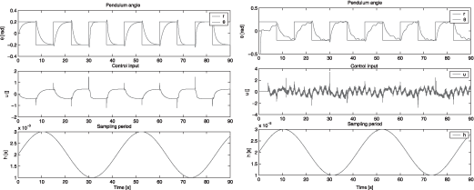
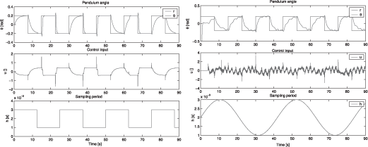
The plant is controlled through Matlab/Simulink using the Real-time Workshop and xPC Target. Two cases are displayed. First, in Figure, 2.12 the sampling period variation is continuous and follows a sinusoidal signal of frequency 0.15 rad s−1. The left plot represents simulation results and the right one a real experiment. As the control interval varies continuously, the controller is adapted at each sample. Therefore, the polytopic coordinates computation 2.46 and convex combination 2.4.3 must be computed previously to the control signal calculation using the state feedback controller 2.45. Anyway, the overall on-line computation remains bounded and simple enough to be easily implemented in real time.
The position reference for the pendulum is a square pattern. Note that the settling time varies with the sampling frequency, accordingly to the definition of the variable weighting functions used for the performance specification. On the right part, the experimental data exhibit additional spikes and noise which are a consequence of dry friction and elasticity (or stick-slip) in the pendulum actuation. However, the experimental plant is still stable and the control signals remain bounded, despite these unmodeled mechanical defects whose effect is known to be difficult to compensate for [OLS 98].
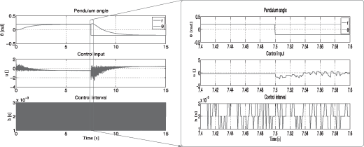
Then, in Figure 2.13, step changes of the sampling rate are experimented. Note that now the controller’s gains computation only needs to be performed at the control interval switches, i.e. in this case, the on-line overhead of the method compared with a classical H∞ controller becomes negligible.
As expected from the sampling-dependent performance objectives, the settling time is minimal when the sampling period is maximal, and conversely. There are no abrupt changes in the control signal, even when the sampling period suddenly varies from 1 to 3 ms. Finally, similar results are obtained in simulation and experimental tests, which illustrates the inherent robustness property of the H∞ design.
Indeed, few assumptions about sampling have been made for this control design. The main point is that the control interval is known and lies between the predefined bounds [hmin; hmax], whatever the origin of the control interval variations, its speed and its frequency. Two cases may be considered:
– the control interval is a control variable which can be used by a feedback scheduler to manage the CPU load share, e.g. as in section 1.4: in that case the desired control interval is computed by a scheduling controller and sent to the real-time scheduler which manages the control tasks execution;
– the control interval variations may be due to sensor scheduling, e.g. induced by a communication channel between the sensor and controller nodes: in that case the interval between the successive expected appearance of data at the controller input are delivered by the scheduling policy controller, e.g. a (m, k)-firm scheduler as defined in section 1.2.2.
Some further simulations, still using the same case study with the “T”-inverted pendulum and associated LPV/H∞-based controller, have been made to illustrate the capabilities and robustness of the method. In the simulation, depicted in Figure 2.14, the control interval has been randomly varied at every sample, with values in the set {1, 2, 3} ms. Indeed, this case mimics data dropping between the sensor and control sites, where the network interface is fed by the sensor at a 1 ms rate, and randomly drops up to two packets out of three with a maximum interval of 3 ms between successful transmission. This transmission pattern may be the result of a feedback scheduler using a (1,3)-firm data-dropping policy to manage the network bandwidth.
Despite the fast and random changes of the control interval, the system remains stable. The settling time conforms with the performance specification, its actual value lies between the performance templates defined with the variable weighting functions for hmin and hmax. The control size remains bounded and reasonably small even with the appearance of chattering. Similar simulation results have been obtained when the control interval varies at every sample with random float values in the specified interval.
This LPV/H∞-based variable sampling control synthesis assumes that the variable parameter, i.e. the control interval in this particular case, is known before the synthesis is performed. Indeed, this is true for the desired interval sent to the operating system by a feedback scheduler, or for the scheduled packets incoming interval on the control node, if jitter is small enough and negligible. However, during control processing and communications between nodes, delays appear due to both the control computation on a real CPU and to pre-emption due to higher priority tasks sharing the control node, and to networking between the sensor, control and actuator’s node if any. These added delays are not known in real time when the controller’s gains computation starts, as they cannot be accounted in the polytopic parameters computation and in the elementary vertex controllers convex combination.
A possible way to cope with these unmodeled and unmeasured delays is to compute at each controller execution a discrete set of control signals (corresponding with the range of expected latencies), send all the set to the actuator’s node, and apply the control signal which best fit the actual measured interval at the actuator node. This is for example the approach of [SAL 09]. A drawback of such an approach is overloading the CPU and network with unused control signals computation and transmission.
In a safely designed and schedulable real-time control system running in nominal conditions, the computing and pre-emption induced latencies are typically smaller than a control period. It is expected that the effect of these quite small latencies can be absorbed by the robustness of the on-board controller. Indeed, the fact that the control experiments depicted in Figures 2.12 and 2.13 are successful, despite nothing was done to model, identify and compensate for the computation and scheduling latencies, indicates that the proposed control design provides such capabilities.
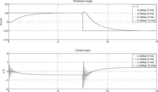
The simulation plot in Figure 2.15 further explores the already used case study robustness w.r.t. unmodeled control delays. The control interval is constant and set to 2 ms, and latencies of increasing values up to 12 ms are added in the control path to simulate unmodeled compound computation and scheduling latencies. It can be observed that the control stability is kept despite quite large added latencies (unstability appears beyond 15 ms delays), while the control quality decreases with the appearance of a classical oscillatory behavior.
Beyond this case study, the robustness of this LPV/H∞ variable sampling control method deserves to be further formally explored, for example using the results exposed in section 2.2. Anyway, this design method already appears to be effective to preserve the plant’s stability and performance objectives during arbitrarily fast control interval variations. Therefore, the method can further be used to cope with varying computing and networking resources availability, for example, as sketched in the state-based feedback scheduler described in section 4.2.
2.5. Summary
Networked control systems are characterized by a complex interaction between heterogenous components and uncertain behaviors. Compared with classical centralized systems, this complex interaction induces disturbances such as latencies due to communication links and protocols, computing durations and pre-emption between concurrent activities. The complexity and combined incertitudes of the components involved in an NCS make untractable an accurate modeling and precise prediction of the timing patterns in control loops. Robust control techniques, which rely on modeling incertitudes bounds rather than on perfect knowledge, are an effective answer to the control of uncertain systems. To this end, section 2.2 provides a summary of results on the control of time-delay systems. Beyond the basic models and theorems of the domain, recent results dealing with time-varying delays are of prime interest for handling network induced delays in control systems.
Section 2.3 deals with a particular model of uncertainty and timing weakly hard constraints. The method works on a slotted timescale and assumes that the control tasks are accelerable, i.e. more executions are performed, better is the control performance. A method to design accelerable controllers for LTI systems is provided, estimation and robustness problems are also addressed. Combining such accelerable controllers with (m, k)-firm policies allows for a smart degradation of the control performance in case of transient overloads of the execution platform.
With the robustness approach control tasks are designed to be tolerant to the timing disturbances. A more active approach is used in section 2.4 to make controllers adaptive to varying known control intervals. An LPV gain scheduling methodology is used, where the variable parameter is the control interval. It is associated with a H∞ design to guarantee both stability and requested performance over all the predefined range of intervals, and provides real-time compliant controllers.
These control designs, which are either robust or adaptive w.r.t. timing deviations, can be further used as building blocks in integrated controllers combining plant control and execution resources constraints, as described later in Chapters 4 and 5.
Note that, while these designs are mainly suited for linear time invariant plants, approaches based on model predictive control, and able to deal with plants nonlinearity, are briefly described in section 4.3.
2.6. Bibliography
[ANT 07] ANTHONIS J., SEURET A., RICHARD J.-P., AND RAMON H., Design of a pressure control system with dead band and time delay, IEEE Transactions on Control Systems Technology, vol. 15, p. 1103–1111, 2007.
[APK 95] APKARIAN P.,GAHINET P., AND BECKER G., Self-scheduled H∞ control of linear parameter-varying systems: a design example, Automatica, vol. 31, p. 1251–1262, 1995.
[ARI 07] ARIBA Y., AND GOUAISBAUT F., Robust stability of time-delay systems with interval delays, 46th IEEE Conference on Decision and Control, New Orleans, USA, December 2007.
[ÅST 97] ÅSTRÖM K. J., AND WITTENMARK B., Computer-Controlled Systems, Information and System Sciences Series, Prentice Hall, Englewood Cliffs, NJ, 3rd edition, 1997.
[BEN 08] BEN GAID M.-M., SIMON D., AND SENAME O., A sesign methodology for weakly-hard real-time control, IFAC World Congress, Seoul, Korea, July 2008.
[BER 01] BERNAT G., BURNS A., AND LLAMOSÍ A., Weakly hard real-time systems, IEEE Transactions on Computers, vol. 50, p. 308–321, 2001.
[BOY 94] BOYD S., ELGHAOUI L., AND FERON E., Linear Matrix Inequalities in System and Control Theory, SIAM, Philadelphia, 1994.
[BRI 08] BRIAT C., Robust control and observation of LPV time-delay systems, PhD thesis, Grenoble-INP, France, 2008.
[CER 03] CERVIN A., Integrated control and real-time scheduling, PhD thesis, Department of Automatic Control, Lund Institute of Technology, Sweden, April 2003.
[CHE 88] CHEN J., ARMSTRONG B., FEARING R., AND BURDICK J., Satyr and the Nymph: software archetype for real time robotics, IEEE-ACM Joint Computer Conference, Dallas, USA, November 1988.
[DAM 94] DAMBRINE M., Contribution à l’étude de la stabilité des systèmes à retards, PhD thesis, Lille University of Science and Technology, France, 1994.
[DEV 05] DEVERGE J., AND PUAUT I., Safe measurement-based WCET estimation, 5th International Workshop on worst-case execution time analysis, Palma de Mallorca, Spain, July 2005.
[DRI 77] DRIVER D., Ordinary and Delay Differential Equations, Springer-Verlag, New York, 1977.
[FRI 02] FRIDMAN E., AND SHAKED U., A descriptor system approach to H∞ control of linear time-delay systems, IEEE Transactions on Automatic Control, vol. 47, p. 253–270, 2002.
[FRI 04a] FRIDMAN E., Stability of linear functional differential equations: a new Lyapunov technique, Proceedings of Mathematical Theory of Networks and Systems, September 2004.
[FRI 04b] FRIDMAN E., SEURET A., AND RICHARD J.-P., Robust sampled-data stabilization of linear systems: an input delay approach, Automatica, vol. 40, p. 1141–1446, 2004.
[FRI 08a] FRIDMAN E., AND NICULESCU S.-I., On complete Lyapunov–Krasovskii functional techniques for uncertain systems with fast-varying delays, International Journal of Robust and Nonlinear Control, vol. 8, p. 364–374, 2008.
[FRI 08b] FRIDMAN E., YEGANEFAR N., AND DAMBRINE M., On input-to-state stability of systems with time-delay: a matrix inequalities approach, Automatica, vol. 44, p. 2364– 2369, 2008.
[GHA 00] GHAOUI L. E., AND NICULESCU S.-I., Advances in Linear Matrix Inequality Methods in Control, Advances in Design and Control Series, SIAM, Philadelphia, 2000.
[GU 97] GU K., Discretized LMI set in the stability problem of linear uncertain time-delay systems, International Journal of Control, vol. 68, p. 923–934, 1997.
[GU 03] GU K., KHARITONOV V. -L., AND CHEN J., Stability of Time-delay Systems, Birkhauser, Basle, 2003.
[HAL 97] HALE J., Theory of Functional Differential Equations, Springer-Verlag, New York, 1997.
[HES 07] HESPANHA J., NAGHSHTABRIZI P., AND XU Y., A survey of recent results in networked control systems, Proceedings of the IEEE, vol. 95, p. 138–162, 2007.
[JIA 05] JIANG X., AND HAN Q.-L., On H∞ control for linear systems with interval time-varying delay, Automatica, vol. 41, p. 2099–2106, 2005.
[KAO 07] KAO C. Y., AND RANTZER A., Stability analysis of systems with uncertain time-varying delays, Automatica, vol. 43, p. 959–970, 2007.
[KHA 01] KHARITONOV V., AND ZHABKO A., Lyapunov--Krasovskii approach to robust stability of time delay systems, 1st IFAC/IEEE symposium on system structure and control, Prague, Czech Republic, August 2001.
[KOL 96] KOLMANOVSKII V., AND SHAĬKHET L., Control of Systems with Aftereffect, American Mathematical Society, Providence, RI, 1996.
[KOL 99a] KOLMANOVSKII V., AND MYSHKIS A., Applied Theory of Functional Differential Equations, Kluwer, Dordrecht, 1999.
[KOL 99b] KOLMANOVSKII V., NICULESCU S.-I., AND RICHARD J.-P., On the Lyapunov– Krasovskii functionals for stability analysis of linear delay systems, International Journal of Control, vol. 72, p. 374–384, 1999.
[KOL 03] KOLMANOVSKII V., AND ZHABKO A., Lyapunov–Krasovskii approach to the robust stability analysis of time-delay systems, Automatica, vol. 39, p. 15–20, 2003.
[KOR 95] KOREN G., AND SHASHA D., Skip-over: algorithms and complexity for overloaded systems that allow skips, 16th IEEE Real-Time Systems Symposium, Pisa, Italy, December 1995.
[LEI 00] LEITH D. J., AND LEITHEAD W. E., Survey of gain-scheduling analysis and design, International Journal of Control, vol. 73, p. 1001–1025, 2000.
[LI 97] LI X., AND DE SOUZA C.-E., Criteria for robust stability and stabilization of uncertain linear systems with state delay, Automatica, vol. 33, p. 1657–1662, 1997.
[LOP 06] LOPEZ I., PIOVESAN J., ABDALLAH C., LEE D., PALAFOX O. M., SPONG M., AND SANDOVAL R., Pratical issues in networked control systems, American Control Conference, Minneapolis, USA, June 2006.
[MIC 04] MICHIELS W., NICULESCU S.-I., MOREAU L., Using delays and time-varying gains to improve the static output feedback stabilizability of linear systems: a comparison, IMA Journal of Mathematical Control and Information, vol. 21, p. 393–418, 2004.
[MON 05] MONDIE S., KHARITONOV V., SANTOS O., Complete Lyapunov-Krasovskii functional with a given cross term in the time derivative, 44th IEEE Conference on Decision and Control, Sevilla, Spain, December 2005.
[MOU 06] MOULAY E., DAMBRINE M., PERRUQUETTI W., YEGANEFAR N., Une première approche de la stabilité et de la stabilisation en temps fini des systèmes à retard, CIFA’06, Bordeaux, France, May 2006.
[NAG 08] NAGHSHTABRIZI P., HESPANHA J., TEEL A., Exponential stability of impulsive systems with application to uncertain sampled-data systems, Systems and Control Letters, vol. 57, p. 378–385, 2008.
[NAT 04] NATALE O., SENAME O., CANUDAS DE WIT C., Inverted pendulum stabilization through the ethernet network, performance analysis, American Control Conference ACC’04, Boston, USA, June 2004.
[NIC 01] NICULESCU S.-I., Delay Effects on Stability. A Robust Control Approach, Springer-Verlag, New York, 2001.
[OLS 98] OLSSON H., ASTRÖM K.-J., DE WIT C. C., GÄFVERT M., AND LISCHINSKY P., Friction models and friction compensation, European Journal of Control, vol. 4, p. 176– 195, 1998.
[PAP 07] PAPACHRISTODOULOU A., PEET M. M., AND NICULESCU S.-I., Stability analysis of linear systems with time-varying delays: delay uncertainty and quenching, 46th IEEE Conference on Decision and Control, New Orleans, USA, December 2007.
[RAM 95] RAMANATHAN P., AND HAMDAOUI M., A dynamic priority assignment technique for streams with (m, k)-firm deadlines, IEEE Transactions on Computers, vol. 44, p. 1443–1451, 1995.
[RAM 99] RAMANATHAN P., Overload management in real-time control applications using (m, k)-firm guarantee, IEEE Transactions on Parallel and Distributed Systems, vol. 10, p. 549–559, June 1999.
[RIC 03] RICHARD J.-P., Time delay systems: an overview of some recent advances and open problems, Automatica, vol. 39, p. 1667–1694, 2003.
[ROB 05] ROBERT D., SENAME O., AND SIMON D., Sampling period dependent RST controller used in control/scheduling co-design, 16th IFAC World Conference, Prague, Czech Republic, July 2005.
[ROB 07a] ROBERT D., SENAME O., AND SIMON D., A reduced polytopic LPV synthesis for a sampling varying controller: experimentation with a T inverted pendulum, European Control Conference ECC’07, Kos, Greece, July 2007.
[ROB 07b] ROBERT D., Contribution à l’interaction commande/ordonnancement, PhD thesis, INP Grenoble, January 2007.
[ROB 09] ROBERT D., SENAME O., AND SIMON D., An H∞ LPV design for sampling varying controllers: experimentation with a T inverted pendulum, IEEE Transactions on Control Systems Technology, in DOI10.1109/TCST.2009.2026179, 2009.
[SAL 05] SALA A., Computer control under time-varying sampling period: an LMI gridding approach, Automatica, vol. 41, p. 2077–2082, 2005.
[SAL 09] SALA A., CUENCA A., AND SALT J., A retunable PID multi-rate controller for a networked control system, Information Sciences, vol. 179, p. 2390–2402, 2009.
[SCH 02] SCHINKEL M., CHEN W.- H., AND RANTZER A., Optimal control for systems with varying sampling rate, American Control Conference ACC’02, Anchorage, USA, May 2002.
[SEU 09a] SEURET A., Lyapunov–Krasovskii functionals parameterized with polynomials, 6th IFAC Symposium on Robust Control Design – ROCOND’09, Haifa, Israel, June 2009.
[SEU 09b] SEURET A., Stabilization of time-delay systems through linear differential equations using a descriptor representation, European Control Conference – ECC’09, Budapest, Hungary, August 2009.
[SEU 09c] SEURET A., EDWARDS C., SPURGEON S., AND FRIDMAN E., Static output feedback sliding mode control design via an artificial stabilizing delay, IEEE Transactions on Automatic Control, vol. 54, p. 256–265, 2009.
[SIM 98] SIMON D., CASTILLO E., AND FREEDMAN P., D esign and analysis of synchronization for real-time closed-loop control in robotics, IEEE Transactions on Control Systems Technology, vol. 6, p. 445–461, July 1998.
[SIN 04] SINOPOLI B., SCHENATO L., FRANCESCHETTI M., POOLLA K., JORDAN M. I., AND SASTRY S. S., Kalman filtering with intermittent observations, IEEE Transactions on Automatic Control, vol. 49, p. 1453–1464, 2004.
[SKO 96] SKOGESTAD S., AND POSTLETHWAITE I., Multivariable Feedback Control: Analysis and Design, Wiley, New York, 1996.
[TÖR 98] TÖRNGREN M., Fundamentals of implementing real-time control applications in distributed computer systems, Real Time Systems, vol. 14, p. 219–250, 1998.
[WIT 01] WITTENMARK B., Sample-induced delays in synchronous multirate systems, European Control Conference, Porto, Portugal, p. 3276–3281, September 2001.
[ZAM 08] ZAMPIERI S., A survey of recent results in networked control systems, Proc. 17th IFAC World Congress, Seoul, Korea, July 2008.
1 Chapter written by Mongi BEN GAID, David ROBERT, Olivier SENAME, Alexandre SEURET and Daniel SIMON.
