
Coal-Burning Technology
The first commercial power station, built by Thomas Edison in New York, started operating in 1882 using steam engines. These engines were quickly superseded by steam turbines which remain the key prime movers for coal plants. The most popular type of coal-fired power station is a pulverized coal station that use coal ground to a powder using mills as fuel. The powdered coal is burnt in a boiler built from walls containing water tubes to collect the heat produced while other water tubes collect the heat in the flue gases exiting the boiler. With this method of construction boilers of up to 1300 MW can be constructed though few are more than 700 MW. Boilers may be sub-critical or super-critical with the latter capable of the highest efficiency, up to 47% in the best case. These high temperature, high pressure boilers must be made from sophisticated alloys to withstand the conditions they experience. Overall power plant efficiency is determined by the Carnot cycle of classical thermodynamics.
Keywords
Thomas Edison; Pearl Street; steam engine; steam turbine; pulverized coal; coal mill; sub-critical; super-critical; fire tube boiler; water tube boiler; water wall; steam drum; superheater; fireball; energy conversion efficiency; furnace temperature
The first commercial power station, Thomas Edison’s Pearl Street station in New York, which opened in 1882, contained all the essential elements that go to make a modern coal-fired power station. The power station burned coal in a furnace, the heat from which was exploited to produce steam in a boiler. This steam was then used to drive a steam engine, in this case a 130 kW reciprocating Porter Allen steam engine, one of the most efficient of its day. The engine changed the heat energy in the steam into a rotary mechanical motion and used this to drive one of Edison’s own “jumbo” dynamos which produced a direct current output of up to 100 kW, sufficient to power 1200 of the inventor’s own incandescent light bulbs. In fact, the station was equipped with six engines and six dynamos and operated virtually continuously until a fire damaged it in 1890.
The reciprocating steam engine had virtually reached the pinnacle of its development in the early 1880s and it was soon overshadowed by the steam turbine which was invented by Charles Parsons in 1884. His first steam turbine drove a 7.5 kW dynamo but size quickly increased and this technology soon replaced the reciprocating engine as the main engine, or prime mover, in a coal-fired power station. From that point on the primary elements – furnace and boiler, steam turbine, and dynamo or alternator1 – have remained virtually unchanged, functionally, although all have become more sophisticated since the end of the nineteenth century. There have been additions since that time too. The most notable are emission control facilities that clean the exhaust gases exiting the furnace and boiler before they are released to the atmosphere. Fuel handling has also changed dramatically from the days when it relied on men with shovels to feed the fuel into the furnace.
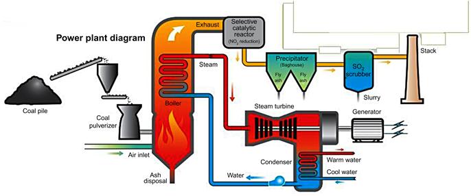
The most common type of coal-fired power station in operation today is called a pulverized coal-fired plant because it burns coal that has been ground into a fine power. A simplified schematic of this type of plant is shown in Figure 3.1. Around 90% of all coal-fired power stations operating today are based on this design. The key elements of such a power plant are: the coal-handling facility which receives and stores the fuel and then prepares it for combustion; the boiler, which today is a single unit combining the furnace and the systems for converting the heat generated by the combustion into steam; the steam turbine which turns the heat energy within the steam into mechanical energy; the generator which converts the mechanical energy into electrical energy; the flue gas treatment systems which clean the waste gases before they are released into the atmosphere.
Coal will usually be delivered to a power plant as mined, unless some mechanical cleaning has already taken place. At the plant some physical sorting will take place before the coal is crushed and milled ready to be injected into the furnace. Inside the furnace, the coal enters a combustion chamber where it burns in the presence of controlled quantities of air to ensure low pollutant production. The heat energy released by the combustion process is then captured in arrays of water tubes that are placed in the path of the hot combustion gases and around the furnace walls so that all radiant and convective heat is collected. Depending on the boiler design, ash may all be carried away with the flue gases from the plant or some may collect at the bottom of the boiler enclosure where it can be extracted and treated for disposal.
Steam exits the boiler at a high temperature and a high pressure. The exact level of each will be determined by the design of the boiler. This steam is then fed into the plant steam turbine. Pulverized coal power plants are normally very large, with generating capacities of up to 1000 MW, sometimes more, and the steam turbines for these plants are made up of multiple turbine units and complex steam flows designed to extract the maximum amount of energy. The turbine units are normally divided into three groups, high-pressure steam turbines, intermediate-pressure steam turbines, and low-pressure steam turbines. The steam exiting the low-pressure steam turbines is finally condensed and returned to the boiler and recycled through the system. There may be a single generator driven by all the turbines or the multiple turbines may drive more than one generator.
The flue gases that exit the boiler after combustion and heat recovery are rich in carbon dioxide and laden with other impurities. These impurities include sulfur dioxide, nitrogen oxides, heavy metals, organic compounds, and tiny ash particles. All these impurities must be removed before the flue gas can be released into the atmosphere. Cleaning is carried out in a sequence of flue gas-cleaning systems, each a separate chemical or filtration plant. Carbon dioxide in not currently removed from commercial coal-fired power plants but technology for its capture is at an advanced stage of development and is expected to be deployed within a decade.
A plant that applies all the available emission control processes, including carbon dioxide capture, may be called a zero emission plant although in fact traces of all the pollutants will still be released. However its environmental impact will be much lower than that of an uncontrolled plant.
Efficiency is the key to modern coal-burning technology and to its future. The higher the ratio of electrical energy produced by the plant to the chemical energy input (the energy content of the coal), the cheaper each unit of electricity produced will be. For modern plants without carbon dioxide capture, higher efficiency also means lower emissions per unit of electricity produced. Alternatively, if carbon capture technologies are added to a plant, with a commensurate loss in efficiency, a high-efficiency plant will potentially still generate electricity economically.
When attempting to maximize the efficiency of a coal-fired power station, some elements of the energy conversion process can be altered by design. Others cannot. Of all the chemical energy contained with the coal, around 15% is lost during the primary energy conversion process, combustion. Much of this is irretrievable. The remainder is released as heat energy so that the hot steam produced by the boiler contains around 85% of the original chemical energy. Converting the hot steam into electricity relies on the Carnot thermodynamic cycle. Conversion efficiency depends on the temperature and pressure of the steam (more accurately the temperature and pressure drop that is achieved between steam turbine inlet and outlet) so the development of modern coal-fired power plant technology is directed at producing steam at the highest temperature and pressure possible. From an energy viewpoint, therefore, the two most important components of a coal-fired power station are the boiler which produces high-temperature, high-pressure steam and the steam turbine which must then convert the energy carried by that steam into electrical energy. However, each of the components in a pulverized coal plant plays a vital role, from the coal-handing systems to the waste gas cleanup system.
Coal Handling
Coal destined for combustion in a pulverized coal-fired power plant is delivered to the power station directly from the mine. If the supplier is domestic, then the delivery will normally be via road, rail, or sometimes by barge if suitable rivers or canals are available. Coal purchased on the global market will be shipped to the country of destination in bulk carriers.
However delivered, the coal will normally be off-loaded and moved by conveyor to the stockyard (or coal pile) where the local supply is stored. The chunk size and condition of the coal arriving at the plant will be determined by the method of mining and transportation.
While some plants will take coal from a single source on a long-term contract, modern market conditions mean that many plants today will receive coal from a variety of different sources. These coals will vary in heat content and the level of impurities, including ash residues, sulfur, and some trace metals, that they contain. Modern high-performance power plants are optimized for coals of a particular specification so operators must keep track of coal consignments in the stockyard and where necessary either mix coals of different quality or alter plant operating conditions to maintain optimum performance. Modern monitoring and simulation software can keep track of the quantity and quality of different coals stored in the plant stockyard and provide visualization to aid management. It should also be able to monitor the moisture content of the stored coal which will vary with levels of rainfall since the stockyard is normally exposed to local weather conditions.
From the stockyard, coal is moved through a system of hoppers and conveyors into the coal processing system. Depending on the size of the power plant there may be several independent processing lines, each feeding one or more of the furnace burners. Coal is first broken down in a coal breaker into pieces of around 2 cm in diameter, though the size will vary depending on the specific plant machinery. The broken coal is then fed into a mill which turns it into a powder.
Coal mills are of differing types. The three main types in use today are ball mills, bowl mills, and hammer mills. A ball mill consists of a rotating cylinder or tube containing steel balls. Coal is introduced into the tube and the tumbling steel balls crush it to powder. A bowl mill uses heavy rollers which run against a steel ring or bowl. As the bowl and rollers rotate against one another, coal introduced into the bowl is crushed between the bowl and the rollers. A hammer mill uses hinged hammers to crush the coal against a steel striking plate. In all types pneumatic transportation (air) is used to transport powdered coal through the mill and on to the burners. This pneumatic transport also allows classification of the powder so that large particles are returned to the mill to be reground while heavy impurities such as iron pyrites are separated from the coal. Typically a mill will be controlled so that 70% of the coal powder it produces will pass through a 200 mesh, indicating a particle size of less than 75 microns. Operation of coal mills is affected by both the moisture content and volatiles content of the coal and so will vary from coal to coal, therefore coal processing must normally be tuned to a particular type of coal.
The powdered coal exiting the mill is carried pneumatically directly to a burner in the combustion chamber. The air carrying the coal forms the primary air for the combustion of the fuel in the boiler furnace. The increasing sophistication of control and automation systems in power stations has led to many of these coal-handling processes from unloading of coal into the stockyard right through to the delivery of powdered coal to the plant boiler and combustion chamber to be automated.
The Development of the Power Plant Boiler
The boiler in a coal-fired power plant (more accurately the combination of the furnace and boiler, but usually referred to simply as the boiler) is the site of one of the two key energy conversion processes that take place in any combustion power plant. The boiler’s role is to release the chemical energy contained in the coal and convert it into heat energy. The heat energy is then carried away as steam produced when the heat is absorbed by water. This heat energy is subsequently converted into electrical energy in the second energy conversion system, the turbine.
The early boilers that were used to supply steam for steam engines were not much more than large kettles. Sometimes called haystack boilers because of their shape, these could provided a large volume of steam but the pressure of the steam was little more than atmospheric pressure. These were soon superseded by more complex designs in which water was contained in an entirely closed, often cylindrical, vessel that allowed a pressure of steam to build up, providing “strong steam” or high-pressure steam to drive an engine. A furnace was placed at one end of this vessel and the hot gases from the furnace passed through a tube which ran down the center of the water-vessel, heating the water and producing steam in a space left at the top of the vessel. This steam was then extracted through pipework and carried to the steam engine. Later boilers extended to the path of the tube carrying the hot furnace gases back through the water (a two-pass boiler) and even back again to create a three-pass boiler and improve heat transfer to the water. These boilers with large flues carrying the combustion gases are generally called flue boilers. A later adaptation was to pass the hot gases through a bundle of small tubes instead of one large one, leading to the development of the main early forerunner of the modern boiler, the fire tube boiler. A version of this type of boiler is shown in Figure 3.2.

A further refinement in some early designs was to superheat the steam created by the main boiler by passing it in pipes through the hot gases before they exited to the stack. This created steam at a higher temperature and pressure and removed droplets of water that are contained in normal steam by heating the fluid well above the boiling point of water. This, in turn, helped prevent damage to the engine components that could be caused by entrained water droplets eroding metal. Superheating also allows more heat energy to be carried by a smaller quantity of water, reducing the size of boiler necessary for a given power production.
Fire tube boilers, in which the combustion gases from the furnace pass through multiple tubes within a large cylindrical pressure vessel containing water, were used for locomotives and in many marine applications but they were limited for stationary applications because they could only achieve a pressure of around 1.7 bar. They were also liable to catastrophic failure in the event that the pressure vessel ruptured and released the pressurized water it contained.
In order to overcome this limitation a new design called a water tube boiler evolved. In this type of boiler the water was passed through bundles of tubes inside the furnace. These tubes ran between a feed-water drum containing cold water at the bottom of the water-steam system and a hot steam drum at the top. The water circulated from the feed-water drum, through the water tubes and then into the steam drum, absorbing heat as it passed through the furnace and eventually generating steam. Steam was then drawn from the top of the steam drum and could be further superheated before being taken to the steam engine or turbine. Steam exiting the turbine was condensed and returned to the feed-water drum. An example of this type of boiler is shown in Figure 3.3.

At first these new water tube boilers used brick furnace enclosures. These designs could generally only produce up to 23,000 kg/h of steam, limiting the size of the power plant they could support. As a consequence many small electricity utility companies grew up in towns and cities, each supplying a small area from these small boiler/turbine systems.
All-brick furnace designs were limited by their structural strength and by the temperatures they could support. The brick walls were up to 56 cm thick in order to retain all the heat generated and as sizes increased absolute size became a limitation. This led to a new design where instead of the water tube bundles being placed in the center of the furnace, the tubes were constructed in the walls. By this means the tubes containing the water would cool the walls of the furnace, controlling heat loss so that thickness could be reduced massively. Lightweight external insulation was then added to reduce residual heat loss further.
The first of this new type of design, called a tube-and-tile furnace, had water tubes fitted into specially shaped fire bricks which formed the furnace wall. This was soon superseded by designs in which the tubes themselves sometimes joined by fins, sometimes joined tangentially, tube to tube, formed the actual internal wall of the furnace. This was the foundation for the modern water wall boiler design. In most recent boilers the boiler is constructed from a membrane water wall in which vertical tubes are linked together by fins in sheets to create the furnace enclosure. Behind the water wall is an insulation layer, which is then capped with external steel lagging.
The development of the water wall design allowed much bigger boilers to be built. Meanwhile the development of the radiant boiler, which had only one drum instead of two, also helped increase capacity. Meanwhile coal preparation and furnace design advanced too. The first pulverized coal boiler was built in 1918, and by the 1930s single boilers capable of delivering 450,000 kg/h of steam were being manufactured. Modern manufacturing techniques developed during the 1950s and 1960s pushed the maximum output of a single boiler to around 1,800,000 kg/h. Since then advances in materials and design techniques have allowed the largest modern boilers to achieve 4,000,000 kg/h or more in a 1300 MW power plant.
Modern Boiler Design
Large pulverized coal plant boilers use water wall construction techniques to build the furnace enclosure in which the coal is burnt. Multiple burners sit in openings in the sides of the boiler enclosure and these feed a mixture of powdered coal and air into the boiler combustion chamber. Combustion takes place under tightly controlled conditions with the aim of creating a fireball in the center of the combustion chamber where the pulverized coal particles burn rapidly, releasing radiant heat which is captured at the walls.2 There is some convective heat transfer too.
Using this method of construction, single pulverized coal boilers have been built to provide steam for steam turbine generators of between 50 MW and up to 1300 MW in capacity. For optimum efficiency a plant needs to be of at least 300 MW but single units capable of more than 700 MW are rarely built because of the effect on an electricity supply system if a single unit of this size or greater should suddenly have to be taken out of service. A simplified cross-section of a large coal plant boiler is shown in Figure 3.4, illustrating the steam and water circuit.

The burners that feed the fuel and air into the combustion chamber are fed from the coal processing systems. The pulverized coal is carried into the combustion chamber from the coal mills using high-temperature air which has been preheated using residual heat from either the boiler or boiler-feed water. This air is called the primary air because it is mixed directly with the coal. The composition of the air/pulverized coal mixture has to be carefully controlled to ensure that combustion takes place under specific chemical conditions. Parameters such as the flame temperature and speed of combustion will depend on factors such as the calorific content of the coal, the amount of ash it contains, and the proportion of volatile material within the coal. As these vary, so the coal-to-air composition must be varied.
The primary air does not normally provide sufficient oxygen for combustion of all the coal in the combustion chamber so the burner nozzle will also be provided with a supply of secondary air, the volume of which can be adjusted to ensure the correct combustion conditions as the coal/air mixture enters the boiler and ignites. (Powdered coal will not ignite easily so when furnaces are started up either oil or gas will usually be used to initiate ignition.)
The number of burners that provide fuel for the combustion chamber will depend on the size of the boiler. Their arrangement can also vary depending upon the design of the unit. Some boilers use burners which are mounted on one side of the chamber only. A second option is to have opposing burners, on facing sides of the boiler. A third option is to have boilers in each corner of the combustion chamber; these are often referred to as tangential burners because they fire their coal and air at a tangent to the fireball in the center of the furnace. In most cases there are no obvious advantages to the different arrangements and it tends to be a matter of the preference of the manufacturer. However, multiple burners do appear to help to create a stable fireball within the furnace.
The temperature of the fireball in the combustion chamber is between 1500–1700°C in the hottest part of the flame (in some cases it can exceed 1800°C) for bituminous coals. For coals with lower calorific content the temperature is likely to be in the region of 1300–1600°C. Under the conditions in the boiler most the ash that remains after combustion is in the form of small particles which are carried away with the combustion gases. These particles are then collected by a gas cleanup system. Boilers of this type are called dry-bottom boilers because there is little or no ash or slag to collect from the bottom of the boiler. Control of the fireball so that it remains in the center of the combustion chamber will also prevent fouling of the water walls that make the furnace enclosure.
The high combustion temperature within the combustion chamber means that nitrogen in coal and air can easily be oxidized to generate nitrogen oxides. In order to prevent this, combustion takes place in stages. During the first stage of combustion the amount of oxygen available is restricted, creating reducing conditions under which most of the oxygen available is captured by carbon during the combustion reaction to create carbon dioxide and none remains to react with nitrogen. As the combustion gases begin to cool, tertiary air is added through ducts higher up within the combustion chamber. The air is sufficient to allow the combustion of carbon to go to completion, while the slightly lower temperature reduces the risk of nitrogen oxide production. Primary combustion can take place in much less than one second. Total particle residence time within the boiler is of the order of 2–5 s. During this time over 99% of the carbon should have been consumed for maximum efficiency.
Actual overall efficiency will depend on the boiler design and on the type of coal. The best plants burning bituminous coals can achieve 45% to 47% net efficiency. However, similar plants burning poorer-quality brown coal or lignite may only achieve 42%. Ambient temperature at the plant site can also affect overall efficiency because it controls the lowest temperature that can be achieved when condensing steam at the exit of the steam turbine.3
There are two overall boiler configurations that are popular for modern pulverized coal-fired power plants, tower boilers and more conventional two-pass boilers. A two-pass boiler consists of the primary boiler and combustion chamber constructed from water walls responsible for the main heat absorption and some water-tube bundles at the top of the enclosure to control the furnace-exit-gas-temperature. The combustion gases then turn through 180° and flow down through an extension of the boiler chamber where additional heat transfer sections are located as tube bundles within the flue gas path. The alternative tower boiler does not turn through 180°. Instead all the heat transfer elements are mounted vertically, one above the other over the combustion chamber. This type of design has become popular in Europe in recent years.
The additional heat transfer elements within both types of boiler include superheaters which are used to heat the steam well above the boiling point of water, economizers that are used to preheat boiler water when it is fed back to the boiler from the condenser (economizers may also be used to preheat combustion air), and reheaters which add additional heat to steam between turbine elements of the station’s steam turbine.
Sub-critical and Supercritical Boilers
The heat released during coal combustion is partly radiant heat and partly convective heat. Radiant heat is captured by water running in tubes within the walls of the combustion chamber. Further collections of tubes are placed in the path of the flue gases exiting the combustion chamber and as water passes from one set of tubes to another its temperature rises and finally steam is generated. In a conventional boiler this will take place within a steam drum which allows the phase change between liquid and gas to proceed smoothly. Steam from the drum may them be superheated to create an even higher-temperature gas.
The efficiency of a steam plant depends on the temperature and pressure of the steam that is delivered to the steam turbine. Improved efficiency can be achieved by increasing both. However, there is a point, as both these increase, at which the nature of water changes and the distinction between the gaseous and the liquid states ceases to exist. Water in this state is said to be super-critical because it has passed the supercritical point in the water/steam phase diagram. The supercritical point for water occurs at 22.1 MPa/374.1°C.
Plants that operate with steam conditions below the critical point are referred to as sub-critical plants and these dominated coal plant construction during the last 50 years of the twentieth century. However, many modern pulverized coal plants now operate with supercritical boilers. Such units require special materials in order to withstand the high temperatures and pressures to which they are exposed. On the other hand, operation under supercritical conditions simplifies the overall steam system configuration because a steam drum is no longer required. Since the gaseous and liquid phases are no longer distinguishable, water can be converted smoothly into steam within the boiler tubing without the need for the drum.
Steam conditions at the exit of a modern sub-critical power plant boiler vary widely but typical figures would be a steam temperature of 540°C and a steam pressure of 17 MPa. Sub-critical plants burning high-quality coals are generally capable of generating electricity with an efficiency of 35–36% though some may reach 38%, depending upon site conditions. Supercritical power plants operate at steam exit temperatures of 540–600°C and at exit pressures of 23–30 MPa. These plants can achieve efficiencies of up to 41%. There is a further sub-division called ultra-supercritical power plants which operate at even higher temperatures and pressures. Although the definition of an ultra-supercritical boiler is not precise,4 plants operating at these more extreme conditions have been capable of up to 47% efficiency under optimum site conditions. In comparison, the average efficiency of coal-fired plants operating across the globe is around 28% and that of the US coal fleet is around 33%.
Ultra-supercritical boilers are not new. Plants were built during the 1950s that operated with steam temperatures of 650°C and a steam pressure of 35 MPa. However, the lack of suitable materials made these plants difficult and expensive to build.
The high temperatures and pressures in supercritical boilers make extreme demands on the materials used to construct them. While steam boilers have traditionally been constructed from steels, conditions in ultra-supercritical power plants require that some components are made from nickel-based alloys similar to those used to construct the high-temperature components used in gas turbines. These materials are more costly than steels.
With further materials development it is expected that future plants will be able to operate at steam temperatures of 700–750°C. This should permit an energy to electrical conversion efficiency as high as 55% to be achieved in a coal-fired steam plant.
While efficiency is the most important factor driving boiler design, flexibility has also been recognized as vital in recent years. Coal-fired power plants have traditionally operated as base load power stations operating essentially at full output all the time. This is no longer the situation everywhere. In some regions coal-fired power stations are being used to support the generation of renewable electricity. This means they have to be able to operate both efficiently and effectively at part load as well as full load and to be able to change output as required by the grid. One technique being used to achieve this is sliding pressure operation under which the steam pressure is allowed to fall as output falls but steam temperature is maintained. With sliding load operation it is possible to maintain relatively high efficiency at part load, even though this may involve falling below the critical point of water.
The construction of the boiler plant also has a major effect on its flexibility. Boiler water walls need to be constructed from thick, strong materials to withstand the most difficult conditions experienced in ultra-supercritical plants. Compared to thinner steels, these will take much longer to heat up or cool down and this thermal inertia can affect the speed at which they are capable of changing their operating conditions. A coal-fired power plant built for flexibility may therefore have to use thinner materials and operate under less extreme conditions, compromising the ultimate level of efficiency it can achieve.
Increasing the steam conditions, allowing greater energy efficiency from the Carnot-cycle controlled steam turbine, is the most important way of increasing plant efficiency but other small measures can also help. For example, capturing and reusing as much heat in the exhaust gases before releasing them to the atmosphere and reducing the condensing pressure at the exit of the steam turbine can also add to overall efficiency, as can using more than one reheat stage between steam turbines in a plant with multiple turbines.