
Novel cycles: humid air cycle systems
Abstract:
This chapter is devoted to gas turbine cycles where water vapor is mixed with air to increase specific power output and efficiency. Basic configurations like steam injected, recuperative water injected and humid air turbine cycles are considered. Mass and thermal balances are reported for each plant, thermodynamic merits and technological drawbacks are illustrated and their performance compared on the basis of homogeneous assumptions. Problems related to operating commercial gas turbine engines in humidified air cycles are also discussed.
5.1 Introduction
The combined cycles so far considered feature a physical separation (i.e., the walls of pipes in the heat recovery steam generator (HRSG)) between the working fluids that flow in the topping gas engine and in the bottoming steam cycle. It is instead possible to conceive a different class of motive power system where air (or combustion gases) and water (or steam) are mixed in specific proportions to create a plant in which Brayton and Rankine cycles are partially operated using the same components (in other words, Brayton and Rankine cycles are arranged in parallel in contrast to the serial configuration of the combined cycle). These systems are usually called humid air turbine (HAT) cycles, but they are often referred to as mixed (gas-steam) or wet gas turbine plants.
HAT cycles have been devised to take advantage of the combined cycle’s high conversion efficiency and the open simple cycle’s low specific costs, provided that these systems eliminate expensive components such as steam turbine, condenser and cooling medium circulation circuit that are required in a combined cycle. This chapter mainly focuses on those systems where H2O is added in a significant fraction (10–15%) of the air mass flow. Nevertheless, injection of steam or water at lower rates has been used in gas turbines over the years as a means of power augmentation and NOx control and the chapter opens with a look at these applications.
5.2 Water mixing for power augmentation and NOx control
Inlet air cooling is a low specific cost method of increasing the gas turbine power output during hot periods. Air cooling can basically be achieved in two ways: liquid water mixing or refrigeration by compression or absorption chillers. Leaving aside the second option, which does not entail air humidification, water mixing can be implemented by either evaporative systems or direct water fogging.
In evaporative coolers, liquid water is distributed over a packing of fibrous corrugated material. The air flow passes through these fibers and is humidified up to over 90% relative humidity and, accordingly, its dry bulb temperature reduces. More important, evaporative cooling increases the fluid density (in terms of kilogram of moist air per cubic meter) at the compressor inlet that on one side lowers the work required to drive the compressor and on the other side increases the actual compressor mass flow rate since in a gas turbine running at constant speed the volumetric flow rate at the compressor inlet is virtually constant, regardless of the air conditions. The final result is that the gas turbine shaft power output increases proportionally to the dry bulb temperature drop. The effect of evaporative cooling can be significant in hot, dry conditions like those considered in Table 5.1. In this case, density increases by 3.6% mainly because of the temperature decay, provided that mass flow addition due to humidification accounts for only 0.47% of the inlet ambient air. For a single-shaft gas turbine, the resulting power output increase may be estimated by standard correction curves [1–3/] to be about 8.5%, whereas heat rate reduces by about 2%.
Table 5.1
Effect of evaporative cooling for ambient air at assigned sample conditions
| Ambient air | Air after evaporative cooling | |
| Dry bulb temperature, °C/°F | 32.0/89.6 | 20.5/69.0 |
| Relative humidity, % | 30 | 90 |
| Wet bulb temperature, °C/°F | 19.4/66.9 | 19.4/66.9 |
| Absolute humidity, gH2o/kgDry Air | 8.9 | 13.7 |
| Specific volume, m3/kgDry Air | 0.877 | 0.850 |
| Density, kg/m3 | 1.15 | 1.19 |
| Molar mass, kg/kmol | 28.81 | 28.73 |
| Ratio of specific heats @ 25°C | 1.394 | 1.391 |
Fogging is an alternative method of increasing moisture of the air flow at the compressor inlet. Water is uniformly sprayed through high-pressure (HP) nozzles to form droplets of 5–20 ^m in diameter that promptly flash in the air stream. Fogging allows even more water to be injected than is needed for air saturation. In this case, some droplets enter the compressor, evaporate in the first rows and produce an intercooling effect which further boosts the power output. On the other hand, fogging requires demineralized water to avoid depositions on the compressor blades, while evaporative cooling may use service water since in the evaporation process only a small amount of liquid water (and salts dissolved in it) is entrained by the air flow.
Spraying water into a mid-stage of the compressor allows even more significant effects to be achieved, given that air temperature is higher and thus more mass can be added to the air flow compared to an inlet injection. Moreover, this solution may also be beneficial at ordinary ambient temperatures or in moist conditions where inlet evaporative cooling is virtually ineffective. This kind of solution has been applied to the General Electric LM6000 SPRINT gas turbine where water injection is accomplished in between the 5-stage low-pressure (LP) and the 14-stage HP compressors [4]. Evaporative intercooling provides a 10% power output increase at ISO condition with nearly unchanged efficiency [5,6].
Injection of humidified air is an alternative option that has been found to be practical for power augmentation during summer peak demand periods. This solution allows over 15% power out increase and 4% heat rate reduction at 35°C ambient temperature on a single-shaft large size gas turbine [7]. An additional air stream (6% of the gas turbine air flow) is compressed by an electrically driven compressor and passed through a humidification tower. Humid air with a water content at the tower exit of approximately 50% by volume (35% by mass) is then injected at any point upstream of the combustor.
Up to the mid-1990s, before widespread adoption of dry pre-mixed com- bustors by all the manufacturers, water and steam injection was the most common solution to control NOx formation in gas turbines equipped with diffusion type burners. Actually, adding a diluent like H2O to the combustion reactants reduces the peak temperature since it takes up a fraction of the fuel heating value and contributes to lowering thermal NOx formation in a diffusion flame. Water mixing at compressor inlet has some effect on NOx but more significant effects can be achieved by injecting water (or steam) directly into the flame via a proper nozzle or by mixing it with the fuel.
Achieving effective NOx containment (i.e., to about 25 ppm when firing natural gas) requires an injection of water corresponding to about 50–100% of the fuel mass flow rate (i.e., 1–2% of the air flow rate at the compressor inlet) or twice that amount of steam. Since water also requires latent heat of vaporization, it is more effective in flame temperature reduction, meaning that a smaller amount of water than steam is needed to accomplish the same flame temperature drop. The injection rate upper limit is set by the increase of carbon monoxide formation and noise problems in the combustor resulting in significant wear of the internal parts [8]. The increased mass flow rate in the expander provides additional power output at the gas turbine shaft. Gas turbine efficiency reduces when water is injected in the combustion chamber due to extra fuel required to vaporize and heat up water. As steam is injected, since it does not need latent heat of vaporization, fuel flow increases at a lower rate than power output so that gas turbine efficiency grows. Nevertheless, when steam is taken from the bottoming Rankine cycle, its power output correspondingly reduces, resulting in a net decrease of the combined cycle efficiency.
In the following sections reference will be made to systems featuring substantially higher H2O additions to improve efficiency compared to simple cycles.
5.3 Steam injected gas turbine (STIG) cycles
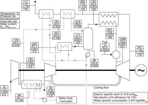
The simplest configuration of a steam injected gas turbine (STIG) cycle is shown in the bottom part of Fig. 5.1 and entails a heat recovery generator where exhaust gases raise a steam flow at a pressure high enough to be introduced in the engine downstream of the compressor or in the combustion chamber. This configuration is the only humidified cycle that finds real application in power generation, and it is also identified with such proprietary names as the Cheng cycle (after Dr Cheng who patented the concept [9] and has commercialized plant retrofits since 1982) or STIG cycle, trade mark of the manufacturer General Electric. In this case steam is injected at a flow rate significantly higher than required for NOx mitigation with the aim of boosting shaft power output and increasing plant efficiency. Steam injected takes part (as diluent) in the combustion and is heated up to the same turbine entry temperature as the combustion gases and then expanded to near ambient pressure. This significantly increases the expander power output without affecting the power required to drive the compressor, therefore producing the same gain on the shaft output.
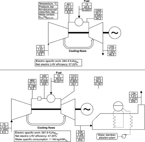
5.1 Plant flowsheets and properties of significant streams for a simple (top) and a steam injected (STIG, bottom) gas turbine cycles with β = 21 and TIT = 1260°C.
5.3.1 Operations of gas turbine components in steam injected cycles
Can a gas turbine engine derived from a unit developed for simple cycle operation withstand such a substantial addition of steam? There are four aspects to this problem:
1. 1. Corrosion issues are a major hurdle in these systems. Therefore the quality of the injected steam must be such as to avoid contamination of elements that may accelerate high-temperature corrosion or even settle depositions on the turbine blades, requiring a treatment unit for water demoralization. Moreover, contaminants and the high moisture content of the working fluid may accelerate degradation of the ceramic thermal barrier coatings used in the hot turbine rows.
2. The addition of steam brings about a substantial increase in mass flow rate that the expander has to pass, resulting in a higher compressor pressure ratio, unless turbine design is modified to allow larger flow sections. Using fixed expander geometry, the maximum steam flow rate injected in the gas turbine is set by the compressor stall limits. Surge margin is generally higher for multi-spool aeroderivative gas turbines, and this is the main reason why all steam injected cycles are based on this kind of engine. Partial STIG is the name given to a configuration where just a fraction of the total amount of steam that could be generated by exhaust heat recovery is utilized in the gas turbine, resulting in lower power output and efficiency compared to the full STIG arrangement.
3. Steam dilution of combustion gases produces a change in the thermo- physical properties of the fluid flowing in the expander that should be taken into account. Major effects are (i) a change in the specific heat and specific heat ratio that determines an increase in the expander enthalpy drop (i.e., higher load on the stages) but a lower temperature drop that consequently increases the turbine outlet temperature for given turbine inlet temperature and pressure ratio; and (ii) an enhancement of the convective heat transfer coefficient on the outer side of the blade that increases the thermal flux with negative consequences on the performance of the cooling circuit.
4. Finally, the considerable increase of the power output must comply with the structural limits of the machine with particular regard to axial thrust on the bearing [10].
5.3.2 Theoretical performance of the STIG plant
The effect of a full steam injection on gas turbine performance is substantial. Figure 5.1 shows a comparison of the operating conditions between simple cycle and full STIG engines based on the same air flow at the compressor inlet, pressure ratio (β, 21) and turbine 1st rotor inlet total inlet temperature (TIT, 1260°C). Performance has been calculated by the simulation code described in References 11 and 12 according to the assumptions listed in Table 5.2. Results show that extensive heat recovery allows a steam mass flow rate of almost 19% of the air flow at the compressor inlet to be produced in the HRSG. Neglecting any constraints on turbine flow capacity and mechanical overload, full steam injection impressively boosts the engine performance. Specific work (defined as shaft output per air mass unit at the compressor inlet) increases by 71% over the simple cycle. Since additional mass flow rate in the combustor calls for a 34% increase of the fuel lower heating value (LHV) input (from 0.93 to 1.24 MJ/kgAir), the resulting efficiency is 47.35%, more than 10% higher than the simple cycle.
Table 5.2
Relevant assumptions considered for cycle calculations
| Design parameter | Assumed value |
| Fuel (natural gas) | |
| Lower heating value, MJ/kg | 44.77 |
| Higher heating value, MJ/kg | 49.62 |
| Turbine 1st rotor inlet total temperature (TIT), °C | 1260 |
| Gas turbine heat losses, % of fuel thermal LHV input at combustor | 0.9 |
| at turbine outlet | 0.3 |
| Combustor pressure loss (Δp/p), % | 4 |
| Pressure drop at compressor inlet (filter), kPa | 1 |
| Pressure drop at turbine outlet (silencer), kPa | 1 |
| HRSG gas side pressure drop, kPa | 3 |
| HRSG pinch point temperature difference, °C | 10 |
| HRSG approach point temperature difference, °C | 25 |
| HRSG thermal losses, % of the transferred heat | 0.7 |
| Recuperator minimum temperature difference, °C | 40 |
| Recuperator hot side pressure drop, kPa | 3 |
| Recuperator cold side pressure loss (Δp/p), % | 3 |
| Recuperator thermal losses, % of the transferred heat | 1 |
| Gas/water heat exchangers minimum temperature difference, °C | 15 |
| Surface inter/after cooler air side pressure loss (Δp/p), % | 2 |
| Surface intercooler minimum air exit temperature, °C | 30 |
| Electric generator efficiency, % | 98 |
| Gas turbine auxiliaries consumption, % of the electric gross power output | 0.35 |
Note: Turbomachines efficiency and coolant flow rates are assumed according to References 11 and 12.]
Because of the combined effects of the higher turbine outlet pressure (due to the HRSG pressure drop) and the lower specific heat ratio (due to steam dilution), gas temperature at STIG cycle turbine outlet is almost 30°C higher than that of simple cycle, despite the enthalpy drop being 12% higher in the former case (1082 vs. 963 kJ/kg) because of the higher specific heat of the humid mixture. The significant efficiency improvement compared with the simple cycle can be mainly explained by the dramatic reduction of stack losses as temperature decreases from 519°C to 124°C, since most of the sensible heat in the exhaust gases is recovered for steam generation. Nonetheless, the efficiency attained by the steam injected cycles is some points below the corresponding combined cycle. This difference is due to two main reasons:
• Mixing steam in the gas stream causes irreversibility because steam is actually taken from its total pressure (30.4 bar in the example in Fig. 5.1) to the partial pressure in the mixed stream (6.2 bar) without any work extraction. Steam is then expanded to a pressure corresponding to H2O partial pressure at the turbine outlet (0.31 bar). In the equivalent combined cycle, steam would be expanded from 30.4 bar to the condensation pressure (usually lower than 0.31 bar) with a larger work extraction.
• In steam injected cycles, water is introduced in the system as liquid and discharged in the vapor phase. Condensation latent heat of H2O contained in the exhaust gases accounts for most of the cycle heat rejection to the environment. This does also occur in a combined cycle where most of the heat is released into the environment by the condenser. The difference in these two processes is their temperature level. While in the condenser of a Rankine cycle heat release occurs at low constanttemperature, vapor condensation in the exhaust gases starts at a higher temperature (69°C in Fig. 5.1). According to Second Law analysis, this temperature difference results in a loss of producible work and, given the large amount of heat associated with H2O condensation (438 kJ/kgAir for a cooling from 69°C to 35°C), it accounts for a significant efficiency decay (about 3% with reference to a 35°C condensation temperature).
In fact these two losses affect the whole arrangement of a HAT cycle and set its thermodynamic efficiency to values slightly lower than combined cycles where these irreversibilities do not take place.
5.3.3 Commercial steam injected gas turbines
Given the limitations described in Section 5.3.1, deriving steam injected plants from simple cycle gas turbine engines leads to a more conservative performance than that shown in Fig. 5.1. Table 5.3reports the main characteristics and performance of commercial plants quoted in Reference 6. For the sake of comparison, data of the corresponding simple cycle models are also shown. It is interesting to note that in the 501-KH5 case a significant steam injection flow rate (almost 18% of the inlet air) produces a 63% increase in specific work compared to the simple cycle engine, and allows efficiency in excess of 40% even in a power plant of a few MW output. This unique characteristic is probably the most appealing feature of steam injected cycles, given that a combined cycle of such small scale would pose insuperable technical and economic feasibility issues. The LM 2500 model also exceeds 40%, but the performance gain is smaller than for the 501-KH5, as the steam injected is limited to about 9% of the air flow rate. Much better performance is shown by the LMS100 model, a gas turbine featuring an intercooled compression that allows a larger pressure ratio than simple cycle, the STIG version of which enables almost 50% efficiency.
Table 5.3
Main characteristic and performance of commercially available STIG plants (lines in bold)
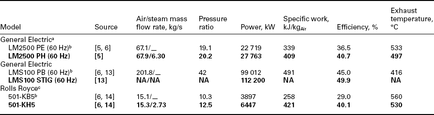
Note: For sake of comparison features of the corresponding models operating in simple cycle are also reported.
aIHI Power Systems and MTU Friedrichshafen commercialize simple cycle and STIGs with similar performance.
bModel with no water or steam injection.
cCentrax commercializes simple cycle and STIGs with similar performance.
A further positive aspect of the steam injected cycle is its flexibility in combined heat and power generation since steam raised in the recovery boiler can be sent to either the gas turbine or the heat consumer, depending on thermal demand and the cost of the electricity. It is moreover possible to increase the steam mass flow rate by means of supplementary firing at the HRSG inlet. In view of these positive features, it is not surprising that dozens of cogenerative STIGs are in operation all around the world.
5.3.4 Proposed configurations for efficiency improvement
For pure power generation the basic configuration cannot compete with combined cycles in terms of efficiency and, therefore, more complex steam injected cycle arrangements have been proposed in the literature with the aim of improving performance. The most interesting modifications involve the following:
• Compression intercooling intended to reduce compressor work and therefore boost power output and enhance efficiency. Intercooling may be implemented through surface heat exchangers or water injection, with a negligible efficiency difference between the two solutions. An additional advantage is that intercooled compression allows the temperature of the flows required to cool the hot parts of the turbine to be reduced, enabling the turbine inlet temperature to be increased with a positive effect on plant performance.
• An alternative solution aiming to increase the turbine inlet temperature consists in the implementation of open circuit steam blade cooling, more effective thanks to the higher heat transfer coefficient and specific heat of steam in comparison with air [15,16].
• Multiple-level steam generation has been proposed to reduce heat transfer losses in the heat recovery boiler. Steam produced at the lower pressure levels is introduced in the gas turbine during expansion while superheated steam produced at the higher pressure can be expanded through a topping steam turbine before injection in the discharge air stream. This allows the HP level to be independent of the gas turbine pressure ratio in order to minimize heat transfer irreversibilities in the HRSG without any work loss.
The combined effects of these changes enable the intercooled compression steam injected cycle to exceed 50% efficiency, with an optimized air-cooled configuration featuring an overall pressure ratio of 36, according to the same simulation model used for performance calculation in Fig. 5.1 [11].
5.4 Recuperated water injected (RWI) cycles
Recuperation of sensible heat contained in the turbine exhausts to increase the temperature of air at the combustor inlet is a widely adopted solution to reduce fuel consumption, thus enhancing system efficiency at the expense of a slight reduction in specific work. Intercooled compression fits very well with recuperation. Intercooling allows a reduction in the compression work while reducing the temperature at the compression end. In the non- recuperative arrangement, intercooling leads to an increase in fuel rate, but recuperation allows this temperature gap to be recovered without any extra fuel consumption, so that the intercooled regenerative (ICR) gas turbine cycle seems an interesting solution to achieve high conversion efficiency. In addition, the ICR cycle combines the excellent part-load behavior typical of recuperative cycles (since the regenerator effectiveness increases as gas flow rate reduces) and a higher insensitivity to ambient temperature provided by the intercooled compression. Currently, the Rolls Royce WR 21 system used for marine propulsion [17] is the only ICR gas turbine set that has entered into a commercial phase.
A flowsheet of an ICR cycle is presented in the top half of Fig. 5.2. The theoretical performance reported has been calculated with the same assumptions, TIT (1260°C) and overall pressure ratio of 21, as the cycles in Fig. 5.1. The same compression ratio (4.64) has been adopted for LP and HP compressors to maximize the cycle-specific output. Data show that inter- cooling allows the compression work to be reduced by 20% compared to the simple cycle while the ensuing lower temperature of air used as coolant reduces the flow rate required for blade cooling at given TIT. The result is that the specific work increases by 24% and efficiency is over 8 points higher than the simple cycle.
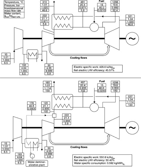
5.2 Plant flowsheets and properties of significant streams for an inter-cooled regenerative (ICR, top) and a recuperative water injected (RWI, bottom) cycles with β = 21 and TIT = 1260°C.
Nevertheless, ICR lacks the thermodynamic ‘quality’ necessary to approach 50% efficiency, mainly because of stack losses resulting from incomplete heat recovery from the exhaust gases. In Fig. 5.2 exhaust gas is released from the stack at 310°C, a temperature much higher than the one achievable in the recovery boiler of a STIG cycle. This is due to the rather high temperature of the air flow at the compressor outlet (222°C) and the significantly larger heat capacity of the stream flowing on the hot side of the recuperator that results in a larger temperature difference at the cold end of the exchanger (88°C vs. 40°C at the hot end) as shown in the temperature- heat duty diagram of Fig. 5.3.

5.3 Temperature-heat duty diagram for the recuperators included in the plant schemes of Fig. 5.2. Transferred heat refers to the air mass unit at compressor inlet.
In the recuperative water injected (RWI) cycle (bottom half of Fig. 5.2), these two drawbacks are simultaneously addressed by mixing the relevant amount of water in the air stream at the compressor discharge (evaporative aftercooling). Two advantages are accomplished in this way: first, a substantial reduction in the temperature of the stream entering the cold side of the recuperator as water vaporization to saturated conditions takes up sensible heat from the gas phase. Second, if the water injected is more than is needed for saturation, heat capacity on the cold side of the recuperator is increased by latent heat required to vaporize the liquid entrained by the gas stream. The best outcome can be achieved by injecting the water flow rate that balances the heat capacities on the two sides of the regenerator; thus the temperature difference at cold and hot ends of the heat exchanger assumes the minimum allowable value (40°C according to current assumptions), as shown in Fig. 5.3. In this case, 45% of the water injected at the compressor discharge remains in the liquid phase and it is evaporated in the regenerator, more than doubling the heat transferred in the component compared to the ICR cycle (from 239 to 494 kJ per kg of air at the compressor inlet). The resulting flowsheet of the RWI cycle is presented in the bottom half of Fig. 5.2. Extensive heat recovery reduces stack temperature to 160°C and takes efficiency over 50%, about 5% higher than the ICR cycle. Simultaneously, water injection augments the mass flow rate in the expander, producing a 29% increase in specific work.
Even if a promising performance is expected from this configuration, no RWI cycle plants have ever been installed or are currently available commercially. Handling evaporation of the liquid water entrained in a two-phase flow inside a gas turbine regenerator is a technological hurdle to the development of this solution, which has been discarded in favor of the evaporative cycles that allow better performance with less challenging design issues, including those associated with water purity.
5.5 Evaporative cycles
The original concept of the HAT cycle was proposed by Dr Rao in 1989 [18] and it has some features in common with the RWI cycle discussed in the previous section. From Fig. 5.4, where the two plants are compared, it can be seen that both are intercooled, regenerative cycles, and the air flow exiting the HP compressor is aftercooled and mixed with water to enhance heat recovery on the turbine exhaust gases with the aim of improving efficiency and specific power. The main difference, outlined by the shaded areas, involves introduction of a surface aftercooler and a saturator instead of a water mixer.
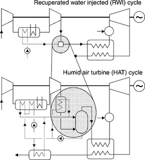
5.4 Simplified plant scheme of the HAT cycle, showing its conceptual derivation from the RWI arrangement.
The saturator, a key component of the HAT cycle, is a vertical tower where hot water flowing from top to bottom is brought into direct contact with air moving upward. In the simultaneous mass and heat transfer process, liquid evaporates into the air stream increasing its humidity and temperature, so that warm, saturated, humid air exits at the top of the tower whereas cold water is released at the bottom. It is analogous to the process that happens in a wet cooling tower, carried out in a different temperature and pressure range. To increase the air–water contact area and residence time of the streams, devices such as trays or packing elements are placed inside the tower. Most of the studies about saturator design (see Reference 19) point to the second option as more effective, that is, it achieves the same heat and mass transfer in a smaller volume and with lower air side pressure drop than a tray tower.
In terms of thermodynamic efficiency, the advantage of the HAT over the RWI cycle can be explained as follows. In the RWI plant, air after- cooling and air/water mixing are accomplished by injecting hot water at a higher rate than that needed for saturation into a relatively high-temperature air stream. During this mixing, the initial difference between the saturation pressure of the liquid water and the partial pressure of water vapor in the gaseous phase (which is a measure of the driving force for water evaporation) is extremely high, resulting in a completely irreversible process.
The basic idea behind the HAT cycle is to reduce this mixing irrevers- ibility by separating aftercooling from water addition. First, air exiting the HP compressor is cooled by means of a surface heat exchanger; then a large quantity of hot water produced in various heat recovery devices is introduced into the air stream in a nonisothermal process.
In the saturator, air gradually heats up along its upward path because of the temperature difference between it and the descending water stream, and it increases its absolute humidity because of the difference existing at each section of the column between the saturation pressure of the liquid water and partial pressure of the water vapor in the gaseous phase. The trick is that the counterflow arrangement keeps those differences to a very limited value with minimal entropy creation inside the saturator.
The HAT arrangement calls for a more complex water loop than RWI. Water is warmed up by recovering heat from compression intercooler, aftercooler and an additional economizer placed downstream of the humid air/exhaust gas regenerator. Compared to the RWI case, there is now room for further heat recovery from the exhausts at the regenerator outlet, since their temperature is considerably higher because the heat capacity on the hot side is substantially higher than on the cold one, given that no water evaporation takes place inside the component. Several plant arrangements have been proposed for HAT cycles in the technical literature and differences among the various proposals mainly concern the number and location of air/water exchangers as well as the distribution of water among the various heat exchangers.
Figure 5.5 shows the complete flowsheet of a basic HAT cycle based on the same pressure ratio (21) and TIT (1260°C) as the previous cases. Intercooling pressure has been set to split the overall pressure ratio exactly equal between the LP and HP sections. Extensive heat recovery required for performance maximization is accomplished by setting the flow rates of the water streams to exactly balance the heat capacities of the streams flowing in intercooler, aftercooler and low-temperature economizer, leading to a water-to-gas mass ratio at the saturator inlet of 0.92. Water stream enters the saturator at 214°C and is cooled to 96°C, provided that an approach temperature difference is required against the wet bulb temperature of the inlet air (equal to 84°C in the example under consideration) to enable the mass transfer from liquid to air stream along the whole column height. About 20% of the inlet water evaporates in the saturator, joining the gas stream that is simultaneously heated from 111 to 150°C. Finally, the HAT cycle can inject more water in the air stream than RWI (0.15 kg of water per mass unit at the compressor inlet vs. about 0.09 for the RWI), achieving an outstanding specific work. The HAT cycle efficiency is almost 2% higher than RWI owing to the less irreversible water mixing process and more comprehensive heat recovery on the exhaust gas.
5.5 Plant flowsheets and properties of significant streams for a HAT cycle with β = 21 and TIT = 1260°C.
5.5.1 Implementation of the humid air turbine (HAT) cycle
Despite the advantages they offer, development of HAT plants is held up by the limited availability of primary ICR units (the above-mentioned Rolls Royce WR 21 model specifically developed for military applications being the only one) or even regenerative cycle. Deviation of the compressor/turbine flow matching from commercial gas turbine design due to the massive water mixing is a second hurdle on the path of actual implementation of HAT cycles. To avoid this problem, the cascaded approach [20] was proposed, consisting of the integration of existing heavy duty gas turbines with an additional shaft including off-the-shelf industrial compressors and HP expander. This proposal has not yet achieved its goals and two small pilot plants are the only evaporative turbine cycles ever run operationally. The first one is located at the Lund Institute of Technology (Sweden) [21] and was constructed at the end of the 1990s as part of a national cooperative research program between universities and industry. The commercial 600 kW recuperative gas turbine module was modified to install aftercooler [22], saturation column and a bleed-off duct to remove a fraction of the air flow at the compressor discharge in order to restore the compressor/expander flow matching. The project enabled successful testing of the humid air combustion system, saturation tower and the related water circuit, which proved self-sufficient: no makeup feedwater was needed owing to the recovery of water condensed after cooling the exhaust gases at the recuperator exit to 35°C. The second plant was built by Hitachi [23] and began operation in late 2006. It is a 3.7-MW plant based on a single-shaft machine, with a two radial stage compressor featuring a pressure ratio of 8.1 and a two axial stage turbine with a 1180°C turbine inlet temperature (first three rows cooled). An atomization system that injects liquid water at the compressor inlet at a rate higher than needed for saturation replaces conventional intercooling of the HAT cycle. The first test round demonstrated system feasibility and confirmed the possibility of achieving target specifications with an LHV efficiency higher than 42%.
The humidification tower, a totally unconventional component for the power generation industry, has been the subject of further experimental activity in the areas of packed columns design [24], tubular humidifiers [25] and spray towers [26].
5.6 Comparative performance analysis of natural gas-fired humidified air gas turbine cycles
A comprehensive comparison of the performance achievable with natural gas-fired gas turbine cycles analyzed in this chapter is presented in Fig. 5.6. It shows that the specified assumptions prevent 40% efficiency from being reached in simple cycle configuration; this value is 1–2% lower than the most efficient aeroderivative engines currently available in the market, operating at pressure ratios over 30.
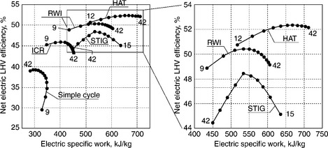
5.6 Efficiency and specific work of the different cycles considered in this chapter. Dots refer to different pressure ratios distributed with step 3 between the minimum and maximum values reported for each curve. All the curves refer to 1260°C TIT Diagram on the right is a zoomed view of the area of the left diagram included in the frame.
The ICR plant takes advantage of regeneration with a significant increase in efficiency, achieving a top value for an overall pressure ratio (15) much smaller than in the simple cycle. It is also worth noting that intercooling brings about a monotonic increase of the cycle-specific work, as pressure ratio rises in the considered range. Regenerative wet cycles (RWI and HAT) reproduce this trend in a higher efficiency band even if HAT is optimized at higher pressure ratio (30). This circumstance can be explained by observing that in ICR and RWI, the lower the pressure ratio, the higher the heat recovery in the regenerator with a positive effect on the overall cycle balance. In HAT cycle, low-temperature heat recovery is accomplished by water heating, leading to a different plant optimization.
Finally, plotting the STIG cycle shows that efficiency rises as pressure ratio increases, reaching the top for β equal to 30, while for higher pressure ratios efficiency quickly decays since losses related to turbine cooling become prevalent. It is worth noting that the STIG cycle is the most severe for the turbine cooling circuit since it associates the high temperature of the cooling air flows (because of non-intercooled compression) to the high heat transfer coefficient on the outer blade wall due to the high moisture content. Figure 5.6 also shows that specific work increases as pressure ratio reduces, since the higher temperature at the turbine exhausts allows more steam to be raised in the HRSG. Cases at β lower than 15 cannot be calculated with the assumptions of Table 5.2 due to a temperature crossover in the HRSG, which could be avoided by increasing the temperature difference at pinch point.
In Table 5.4 the cycles at their respective optimized pressure ratios are compared in terms of the Second Law analysis. By far the two largest irre-versibilities of the simple cycle are due to combustion and the discharge of hot gases to ambient, which, taken together, cause an efficiency loss approaching 50%. All the complex cycles succeed in achieving dramatic reductions of the discharge loss, but none can sensibly affect combustion loss. The only two ways to reduce this irreversibility are either an increase of TIT or an increase of the air flow temperature at the combustor inlet. The cases in Table 5.4 are all calculated at the same TIT, and pressure ratio optimization leads to comparable combustor inlet temperature provided that non-recuperative cycles operate with higher β. Although all mixed cycles have a somewhat similar loss distribution, two conclusions can be drawn about the specific merits (and drawbacks) of the various solutions:
Table 5.4
Second Law analysis of various dry and humidified air cycles at their optimal pressure ratio
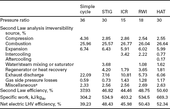
Notes. Second Law efficiency is in the same proportion to the net electric LHV efficiency since the fuel at cycle inlet is considered at the same conditions for all the five cases.
aThis item includes electric/mechanical losses, auxiliaries consumption and water pumping losses.
• The STIG cycle is significantly penalized by steam mixing losses (more than 3.5 points), and the single pressure level HRSG arrangement makes for substantial heat transfer irreversibility, much higher than that occurring in the recuperator of RWI, or in the whole recuperator-saturator of HAT.
• The superiority of the HAT cycle over its competitors is mainly due to the more efficient heat transfer and mixing mechanism accomplished in the saturator, and to the capability of efficiently recovering the inter-cooling heat.
5.7 Water quality and condensate recovery
As mentioned above, gas turbines are sensitive to high-temperature corrosion, deposits and degradation of materials (especially coatings) due to contaminants contained in the inlet air flow, fuel stream and water in those cases where it is mixed into the working fluid. When water or steam is directly injected in the gas turbine (including inlet fogging or evaporative intercool- ing), high quality demineralized water is required, resulting in increased capital and operational costs. Most stringent limits actually relate to RWI and STIG cycles with once-through boilers since all solids dissolved in the make-up water are actually entrained in the working fluid of the gas turbine cycle. In drum type HRSGs, concentration of solids in the steam injected into the gas turbine (to be retained below 150 parts per billion according to Reference 27) is not directly correlated to the make-up quality since salts can build up in the water circulating in the evaporator and be eliminated via a blowdown line. Nevertheless, limits on the concentration of solids in the boiler actually requires use of demineralized water. The same is true for evaporative cycles. Since only water evaporates in the saturator and effective separation of droplets at the top of the tower can reduce the risk of solids entrainment in the air stream, lower quality water could in theory be used in a HAT cycle, provided that contaminants remaining in the liquid phase are removed. For this specific reason, Fig. 5.5 includes a water treatment plant (filtration, softening) rather than the demineralization plant indicated for STIG and RWI plants.
Water-specific consumption (reported for the different cycles in Figs. 5.1, 5.2 and 5.5) ranges from 0.592 kg/kWh of generated electricity for the RWI cycle to 1.15 kg/kWh for the STIG plant. Such values are fully comparable with water consumption of combined cycles using wet cooling towers. In humidified air turbine cycles, water consumption can even be reduced to zero by recovering water contained in the exhaust gases cooled to a temperature low enough (between approximately 30 and 40°C as long as a suitable heat sink is available without requiring wet cooling towers) to allow condensation of flow rate equivalent to water injected. More water (humidity of inlet air and formed by fuel oxidation) remains in the gas stream and is released to stack. Feasibility of water recovery has been demonstrated by the HAT pilot plant in Lund. Obviously, the cost for a water recovery system that condenses water must be compared with the one of fresh make-up water. Macchi and Poggio[28] reported the case of a cogenerative STIG plant located in an Italian car manufacturing factory, where high demand for low-temperature heat for the body paint shop made it convenient to recover water, which resulted in better quality than fresh make-up.
5.8 Further application of humid air turbine (HAT) cycles
A variation of the steam injected cycle is the chemically recuperated configuration shown in Fig. 5.7. The rationale behind this plant is to improve heat recovery from the turbine exhausts to support the endothermic reforming reactions involving fuel hydrocarbons; thus,
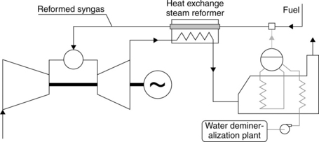
5.7 Plant scheme of a chemically recuperated steam injected cycle, based on natural gas-steam reforming.
Since the overall reaction is endothermic, the comprehensive heating value of the reformed synthesis gas (syngas), rich in hydrogen (H2) and carbon monoxide (CO), is higher than that of the reacting hydrocarbons. Elevated temperatures and low pressures favor higher conversion of the reactants, leading to a lower optimum pressure ratio than the STIG cycle. Nevertheless, steam reforming of light hydrocarbons included in natural gas is very limited at the temperatures typically available at the gas turbine exhausts, and the resulting efficiency increase over conventional steam injected cycle is less than 1% [29].
Even if most of the technical literature deals with internal combustion of natural gas-fired plants, there are some alternative configurations that are worth mentioning. Since the outstanding performance of the HAT cycle mainly stems from a very efficient handling (from the Second Law point of view) of low-temperature heat in the saturation process, evident synergies can be obtained with the cheaper (than syngas cooler option) full quench gasification process. In this case the low-temperature heat available from syngas cooling after water quench is used to produce hot water to enhance the saturator duty. Since the humidified air cycles are less susceptible than combined cycle to efficiency decay and specific cost increase induced by the small scale, the HAT system could be an attractive option in connection with biomass gasification plants whose size is often constrained by feedstock availability.
Another interesting application of the humid air cycle would be in plant implementing CO2 capture for carbon sequestration. The key advantage resides in the high concentration of water in the turbine exhausts that can be easily removed by condensation, increasing the CO2 concentration in the stream and consequently making CO2 capture easier. Further increases of CO2 concentration in the treated stream could be achieved by recirculating a fraction of the exhaust gas at the compressor inlet in order to substitute excess air (i.e., air in addition to stoichiometric amount required for fuel oxidation) usually present in gas turbine cycle to moderate combustion temperature.
5.9 Conclusions
This chapter has presented the rationale leading to the introduction of water or steam mixing in gas turbine engines to overcome the limitations of the simple and recuperative cycles.
The most distinctive plant arrangements of wet gas turbine plants were illustrated. Their energy balances have been calculated on a homogeneous basis and compared in terms of First and Second Law analysis.
The study showed that LHV efficiency above 52% can be achieved by humid air cycle systems, a value that does not allow them to compete with large-scale combined cycles for base load power generation. This efficiency difference tends to disappear as the plant size decreases to the point that for a few MW output, where a combined cycle would pose insuperable technical and economical feasibility issues, steam injected cycles are currently the only commercial solution enabling in excess of 40% efficiency along with unmatched flexibility in combined heat and power generation.
5.10 Sources of further information
A large number of papers related to HATs have been issued in the past 30 years, but the 1990s can be considered a sort of ‘golden age’ for this subject, given that major theoretical and experimental studies have been carried out in that period. Therefore, the comprehensive review paper prepared by Jonsson and Yan in 2003, [30], which includes an exhaustive bibliography to that date, remains a topical reference. Two more recent papers [31,32] investigate the fundamental issue of the thermophysical properties of humid air for calculation and design of power cycles.
A basic theoretical analysis of dry and wet gas turbine cycles can be found in [33], whereas classic books can be useful where more fundamental subjects are concerned. References 34 and 2 can be recommended with regard to analysis of the compressor/turbine flow matching, a primary problem in HAT cycles. Finally, Reference 35 supplies theoretical bases for understanding mass transfer mechanism and design criteria of HAT saturators.
5.11 References
[1] Brooks, F.J. GE Gas Turbine Performance Characteristics’. GE Report GER 3567H, October 2000, downloaded from link http://www.gepower.com/prod_serv/products/tech_docs/en/downloads/ger3567h.pdf. [on 8 Feb. 2011].
[2] Razak, A.M.Y., Industrial Gas Turbines: Performance and Operability, Woodhead Publishing, Cambridge, UK, ISBN 978-1-84569-205-6, 2007.
[3] Ansaldo Energia, Correction curves for gas turbines V64.3, V84.3, V94.3, personal communication.
[4] Badeer, G.H. GE Aeroderivative Gas Turbines – Design and Operating Features. GE Report GER 3695E, October 2000, downloaded from link http://www.gepower.com/prod_serv/products/tech_docs/en/downloads/ger3695e.pdf. [on 8 Feb. 2011].
[5] General Electric Energy. LM6000 Sprint Gas Turbine Generator Set Brochure, downloaded from link http://www.gepower.com/prod_serv/products/aero_turbines/en/downloads/lm6000_sprint.pdf. [on 8 Feb. 2011].
[6] World, Gas Turbine. Handbook; Vol. 28. Pequot Publication, Fairfield, CT, 2010. [2010].
[7] Akita, E., Gomi, S., Cloyd, S., Nakhamkin, M., Chiruvolu, M., The air injection power augmentation technology provides additional significant operational benefits. Proceedings of ASME Turbo Expo 2007, Montreal, Canada, ASME paper GT2007 – 28336, 2007. [DOI: 10.1115/GT2007–28336.].
[8] Schorr, M.M., Chalfin, J. Gas Turbine NOX Emissions Approaching Zero – Is It Worth the Price. GE Report GER 4172, September 1999, downloaded from link http://www.gepower.com/prod_serv/products/tech_docs/en/downloads/ger4172.pdf. [on 8 Feb. 2011].
[9] Cheng, D.Y. Regenerative Parallel Compound Dual-Fluid Heat Engine. US Patent No.. (4128994):December 1978.
[10] Fischer, A.C., Frutschi, H.U., Haselbacher, H., ‘Augmentation of gas turbine power output by steam injection’, Proceedings of ASME Turbo Expo 2001, New Orleans, LA, USA, ASME paper 2001-GT-0107, June 2001.
[11] Macchi, E., Consonni, S., Lozza, G., Chiesa, P. An assessment of the thermodynamic performance of mixed gas-steam cycles: Part A – intercooled and steam- injected cycles. Journal of Engineering for Gas Turbines and Powe. 1995; 117:489–498. [DOI: 10.1115/1.2814122].
[12] Chiesa, P., Macchi, E. A thermodynamic analysis of different options to break 60% electric efficiency in combined cycle power plants. Journal of Engineering for Gas Turbines and Power. October 2004; 126:770–785. [DOI: 10.1115/1.1771684].
[13] Reale, M.J. New High Efficiency Simple Cycle Gas Turbine – GE’s LMS100™’. eneral Electric report GER-4222A (06/04), downloaded from link http://www.gepower.com/prod_serv/products/tech_docs/en/downloads/ger4222a.pdf. [accessed 8 Feb. 2011].
[14] Rolls Royce plc website http://www.rolls-royce.com/energy/energy_products/gas_turbines/501/ [accessed 8 Feb. 2011].
[15] Chiesa, P., Consonni, S., Lozza, G. Gas/steam cycles with open-circuit steam cooling of gas turbine blades’, Proceedings of the ‘Florence World Energy Research Symposium 1992. Florence, Italy. June 1992; 303–323.
[16] Cleeton, J.P.E., Kavanagh, R.M., Parks, G.T. Blade cooling optimisation in humid-air and steam-injected gas turbines. Applied Thermal Engineering. November 2009; 29:3274–3283. [10.1016/j.applthermaleng.2009.04.034].
[17] Rolls Royce plc website http://www.rolls-royce.com/marine/products/diesels_gas_turbines/gas_turbines/wr21.jsp [accessed 8 Feb. 2011].
[18] Rao, A.D. US Patent No. 4829763 Process for producing power. 1989.
[19] Aramayo-Prudencio, A., Young, J.B. ‘The analysis and design of saturators for power generation cycles: Part 1 – Thermodynamics’, Proceedings of ASME Turbo Expo 2003, Atlanta, GA, USA, ASME paper GT2003–38945. June. 2003. [doi: 10.1115/GT2003-3 8945].
[20] Nakhamkin, M., Swensen, E.C., Wilson, J.M., Gaul, G., Polsky, M. The cascaded humidified advanced turbine (CHAT). Journal of Engineering for Gas Turbines Power. July 1996; 118:565–571. [doi: 10.1115/GT2003-3 8945].
[21] Agren, N.D., Westermark, M.O., Bartlett, M.A., Lindquist, T. First experiments on an evaporative gas turbine pilot power plant: Water circuit chemistry and humidification evaluation. Journal of Engineering for Gas Turbines Power. January 2002; 124:96–102. [doi: 10.1115/1.1397778].
[22] Thern, M., Lindquist, T., Torisson, T. heoretical and experimental evaluation of a plate heat exchanger aftercooler in an evaporative gas turbine cycle. Proceedings of ASME Turbo Expo 2003, Atlanta, GA, USA, ASME paper GT2003–38099, 2003. [DOI: 10.1115/GT2003–38099].
[23] Higuchi, S., Koganezawa, T., Horiuchi, Y., Araki, H., Shibata, T., Marushima, S. Test results from the advanced humid air turbine system pilot plant: part 1 – overall performance. Proceedings of ASME Turbo Expo 2008, Berlin, Germany, ASME paper GT2008–51072, 2008. [DOI: 10.1115/GT2008–51072.].
[24] Traverso, A. Humidification tower for humid air gas turbine cycles: Experimental analysis. Energy. February 2010; 35:894–901. [10.1016/j. energy.2009.07.021].
[25] Dalili, F., Westermark, M. Experimental results on humidification of compressed air in a tubular humidifier for evaporative cycles. Proceedings of ASME Turbo Expo 2003, Atlanta, GA, USA, ASME paper GT2003–38034, 2003. [DOI: 10.1115/ GT2003–38034].
[26] Xu, Z., Xiao, Y., Wang, Y. Experimental and theoretical studies on air humidification by a water spray at elevated pressure. Applied Thermal Engineering. October 2007; 27:2549–2558. [10.1016/j.applthermaleng.2007.01.032].
[27] Gallo, W.L.R. A comparison between the HAT cycle and other gas-turbine based cycles: Efficiency, specific power and water consumption. Energy Conversion and Management. October 1997; 38:1595–1604.
[28] Macchi, E., Poggio, A., ‘Cogeneration plant based on a steam injection gas turbine with recovery of the water injected: design criteria and initial operating experience’, Proceedings of ASME Turbo Expo 1994, The Hague, The Netherland, ASME paper 94-GT-17, June 1994.
[29] Lloyd, A. Thermodynamics of Chemically Recuperated Gas Turbines. CEES Report 256, Princeton University, Princeton, NJ, USA, January 1991, downloaded from link www.princeton.edu/pei/energy/publications/reports/No.256.pdf. [on 8 Feb. 2011].
[30] Jonsson, M., Yan, J. Humidified gas turbines – a review of proposed and implemented cycles. Energy. June 2005; 30:1013–1078. [DOI:10.1016/j.energy.2004.08.005].
[31] Herrmann, S., Kretzschmar, H.J., Teske, V., Vogel, E., Ulbig, P., Span, R., Gatley, D.P. Properties of humid air for calculating power cycles. Journal of Engineering for Gas Turbines and Power. September 2010; 132:093001–093008. [DOI:10.1115/1.4000611].
[32] Jia, X., Yan, J. Thermodynamic properties for humid gases from 298 to 573 K and up to 200 bar. Applied Thermal Engineering. 2006; 26:251–258. [DOI: 10.1016/j.applthermaleng.2005.05.005.].
[33] Horlocj, J.H. ISBN 0-08-044273-0Advanced Gas Turbine Cycles. Oxford, UK: Elsevier Science, 2003.
[34] Saravanamuttoo, H.I.H., Rogers, G.F.C., Cohen, H., Straznicky, P.V.Gas Turbine Theory. Harlow, UK: Pearson Education Limited, 2009. [ISBN 978-0-13222437-6,].
[35] Treybal, R.E. ISBN 0070651760 Mass-Transfer Operations (3rd editio. McGraw-Hil, Boston, MA, USA, 1987.