
In this chapter you will gain an understanding of network fundamentals needed to understand network security, and you will also learn about security zones. Being familiar with the basic network architectures and protocols is the first step. Understanding other routing and address translation will help you to further understand the vulnerabilities and threats that can be exploited.
- 1.
Explain the security function and purpose of network devices and technologies.
- 2.
Implement secure network administration principles.
- 3.
Differentiate network design elements and compounds.
- 4.
Use common protocols to employ infrastructure security.
- 5.
Identify commonly used default network ports.
Network Architectures

Technology Architecture Acronyms
Local Area Network (LAN): A local area network is a computer network that interconnects computers in a smaller geographic area.
Metropolitan Area Network (MAN): A Metropolitan area network is a network designed for a specific geographic locality such as a town or a city.
Wide Area Network (WAN): A wide area network covers a larger geographic area such as a regional or national boundary. The Internet is an example of a WAN.
Campus Area Network (CAN): A campus area network is a computer network that is made up of an interconnection of local area networks (LANs) within a limited geographical area.
Network Topology
Ring Topology: In a ring topology, each device is directly connected to two other devices forming a closed loop. What do you suppose will happen should one of the devices fail? If you said “bring down the network,” you would be correct, which is a big disadvantage of this topology.
Bus Topology: Network components that are connected to the same cable, sometimes called “the bus,” are arranged in the bus topology.
Star Topology: With the star topology, network components are connected to a central point such as a hub or a switch. Larger networks may use more than one topology at the same time resulting in a mixed or hybrid topology.
Mesh Topology: In a mesh topology, all the network components have a direct point-to-point link with every other network component.
Hybrid Topology: A hybrid topology is a combination of two or more topologies. For example, a ring and a bus topology can be combined together to create a hybrid topology.
Now that you’ve learned how a network topology describes how a network is physically arranged, it’s important to understand that you can use the same terms to describe the logical topology, the way in which data are transmitted between network nodes. To make matters a little more confusing, a network’s logical topology does not necessarily match its physical topology.
Network Protocol

Types of Network Protocols
Ethernet : The IEEE 802.3 standard specifies all forms of Ethernet media and interfaces. Ethernet is the most widely implemented LAN standard.
TCP/IP : If you browse the Web, then you are using the Transmission Control Protocol/Internet Protocol more commonly referred to as TCP/IP. TCP/IP is a suite of specialized protocols and has become the standard because it is open; rather than proprietary, it is flexible, and it is routable.
Sub-protocols : When you surf the Web, you will be using a few of the sub-protocols including dynamic host control protocol (DHCP), hypertext transfer protocol (HTTP), file transfer protocol (FTP), and domain name system (DNS). When you turned on your computer, the computer requested an IP address from the DHCP server. All devices that want to use the Internet require an IP address. After opening your browser, you type in the name of the website that you wish to visit, for example, www.cssia.org/. A server running the domain name system (DNS) translates the easily remembered domain names that we use into its IP address equivalent. The home page from the CSSIA site is then displayed in your browser.
Protocols are used throughout networking to provide communication standards. The Institute of Electrical and Electronics Engineers (IEEE) is a professional association and is one of the leading networking standards organizations.
IEEE 802.11 : IEEE 802.11 is the standard for wireless networking. Communication protocols that define how wireless LANs operate.
The OSI Model
In the 1980s, a universal set of specifications were developed that would enable any computer platform to communicate openly. The result was the Open Systems Interconnection (OSI) model. The OSI model is useful for understanding computer-to-computer communications over a network.
The model is divided into seven layers. At each layer, protocols perform services that are unique to that layer. The protocols for that service also interact with protocols in the layers directly above and below. At the bottom, you have the Physical layer services that act on the network cables and connectors to issue and receive signals. At the top, you have the Application layer protocols that interact with the software that you use such as an email program or a web browser.
The OSI model is a theoretical representation of what happens between two nodes communicating on a network. For specific details regarding each layer and a graphic representation read “'How OSI Works” (https://electricalacademia.com/computer/osi-model-layers-functions/).
IP Packet
In order for networks to share information and resources, rules must be followed for effective communication. A large amount of data must be broken into smaller, more manageable chunks called packets before transmission can occur from one computer to another. Each protocol has its own definition of a packet.

Graphic Breakdown of an IP Packet into Two Main Sections: The Header and the Data, Also Called the Payload
TCP vs. UDP
It is important to understand the differences between a Transmission Control Protocol (TCP ) and a User Datagram Protocol (UDP). A UDP is a connectionless, unreliable protocol, while Transmission Control Protocol (TCP) is connection-oriented and ensures that packets are processed in the same order in which they were sent.
When you send a package with FedEx, you have a tracking number that you can use to make sure that the package was received by the intended party, very similar to TCP. Contrast this scenario with that of sending mail by depositing it in a mailbox. You hope that the other party receives it, but you cannot track it. You do not receive a confirmation that it arrived. This second scenario is much like UDP.
Three-Way Handshake

Three-Way Handshake Pattern
This pattern is referred to as the three-way handshake. To illustrate this pattern, let’s use a phone call. You call your friend—that is the SYN. When your friend answers the phone and says “hello”—that is the SYN/ACK. When you respond, that is the ACK. Now, the conversation is ready to go forward. Because TCP is guaranteed and reliable, it is popular for many network applications and services such as HTTP, FTP, and Telnet.
Internet Control Message Protocol (ICMP)
If a remote network is available
The length of time to reach a remote network
The best route for packets to take when traveling to another network
The ping command uses ICMP to determine whether the host on the other end of the command can be reached. Unfortunately, the ICMP protocol has also been used to execute denial-of-service (DoS) attacks because the packets are so small and can be generated by a single system in a short period of time.
Packet Delivery

Types of Packet Delivery
Local Packet Delivery

Illustration of a Local Packet Delivery Process Including the Five Steps Used to Indicate What Occurs to Arrive at www.cssia.org
Remote Packet Delivery
Remote packet delivery uses the IP address. IP addresses are 32-bit numbers that are usually referred to in their decimal equivalent, like 192.168.1.100. Before sending a packet, the system will first determine if the destination IP address is on a local or remote network. After determining that the packet is indeed destined for a remote network, it forwards the packet to the network gateway, the router.
Routers are used to interconnect networks, and the process of moving packets from one network to another is called routing. If a router does not know where the destination network is, it forwards the packet to its defined gateway. This process is repeated until the packet arrives at the router serving the destination network. At this point, the router will use local packet delivery to forward the packet to the appropriate MAC address of the destination system.
Domain Name System (DNS)
The domain name system (DNS) is a hierarchical naming system for any resources connected to the Internet or a private network. DNS translates the domain name, cssia.org, to its IP address, 67.179.77.158. Most of us cannot remember a bunch of IP addresses for the websites that we visit. Domain names are much easier for us to remember. Review Figure 2-6, which provides an example of a local packet delivery process using images, directional arrows, and numbers identifying what occurs at each step.
Routing
Routing is the process of moving packets between networks. A router is the network device that forwards packets between networks. Routers use forwarding tables to determine where a packet goes. You may have a cable modem, a router which connects to the Internet through an Internet service provider more commonly known as an ISP. Routers look at the destination address to determine where to send the packet.
IP Addressing
As previously mentioned, IP addresses are 32-bit numbers represented as 4 groups, or octets, of 8-bits each and are commonly referred to in their decimal equivalents rather than the binary representation. Of the 32 bits, some are used for the network portion of the address, and the others are used for the host portion of the address.
Subnetting
Subnetting is used to divide the 32 bits into the network portion of the address vs. the host portion of the address. The subnet mask is used. For example, you may have an IP address of 192.168.1.100 and the subnet mask is 255.255.255.0 which is the default Class C subnet mask. Therefore, the first three octets represent the network portion of the IP address (192.168.1.0), and the last octet represents the host portion of the address. When TCP/IP is configured on a device, both an IP address and a subnet mask are required.
Classes of Network Addresses
Class A: 0.0.0.0 thru 126.255.255.255
Class B: 128.0.0.0 thru 191.255.255.255
Class C: 192.0.0.0 thru 223.255.255.255
Class D: 224.0.0.0 thru 224.0.0.0 (multicast)
Class E: 240.0.0.0 thru 255.255.255.255 (reserved)
Reserved Addresses
Types of Reserved Addresses
Table head | |
|---|---|
Unusable addresses | Broadcast address: 10.10.10.255 Subnet network address: 10.10.10.0 |
Automatic private IP address | 169.254.0.1 thru 169.255.255.254 |
Loopback address | 127.0.0.1 |
Private addresses | .0.0.0 thru 10.255.255.255 172.16.0.0 thru 172.31.255.255 192.168.0.0 thru 192.168.255.255 |
Private IP addresses fall into three ranges. These addresses are commonly used in home, office, and corporate networks and were originally intended to delay having the IPv4 addresses run out. Private addresses are not allocated to any specific organization, and IP packets addressed by them cannot be transmitted onto the Internet.
Classless IP Addressing
Classless IP Addressing is used to reduce the wastage of IP addresses in a block. There is no fixed length for the network and hosts as it is fixed in the classful IP addressing. In classless IP addressing, the number of bits for network mask are defined with the IP address with a symbol “/”.
Network Address Translation (NAT)

Illustration of How NAT Is Used to Modify IP Address Information As Described in the Preceding Section
Many home networks use NAT, a feature found in routers, so that multiple hosts on the home network can access the Internet using a single public IP address.
Security Zones
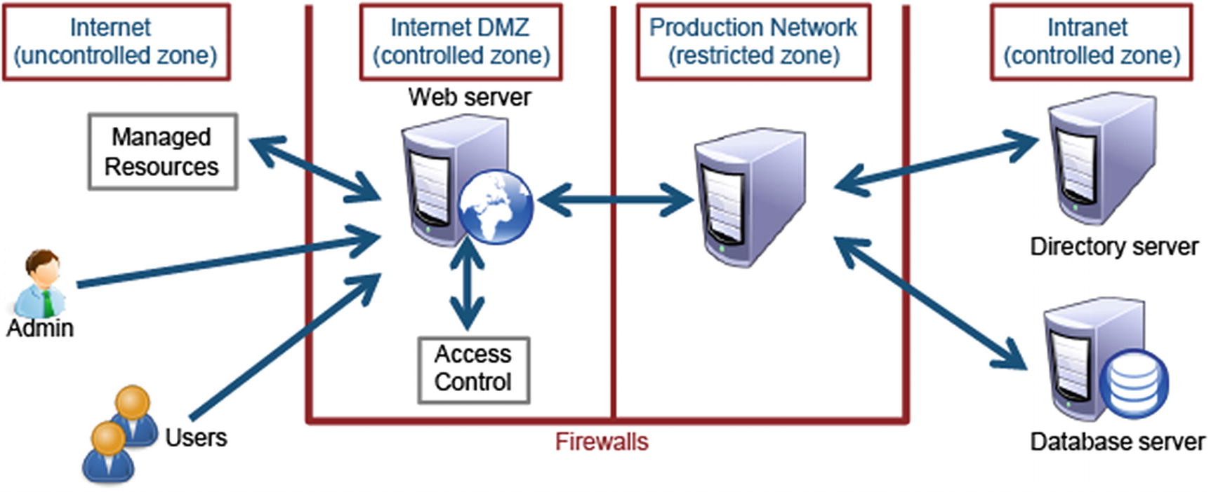
Graphic Illustration of Security Zones Serving As a Layered Defense
Demilitarized Zone
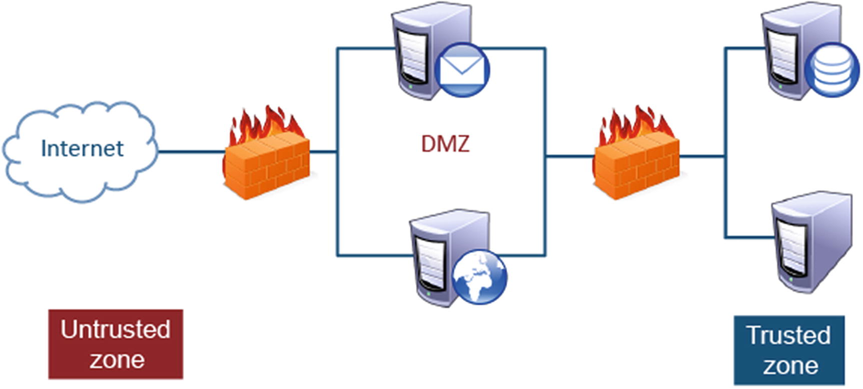
Image Illustrates the Use of a Demilitarized Zone (DMZ) Acting as a Buffer Zone Between the Unprotected Areas, the Internet, and a Trusted Zone, Protected Company Data Stores. The DMZ Allows Traffic Between the Two Zones to be Monitored and Regulated
Virtual LAN (VLAN)

Image Illustrates the Configuration of VLANs Connected to Different Physical Networks on the First and Second Floors of a Building to Indicate that Individuals in a Sales Department on the First Floor Can Communicate with and Share Resources Using Their Computers with Individuals in a Human Resource Department on the Second Floor
Tunneling
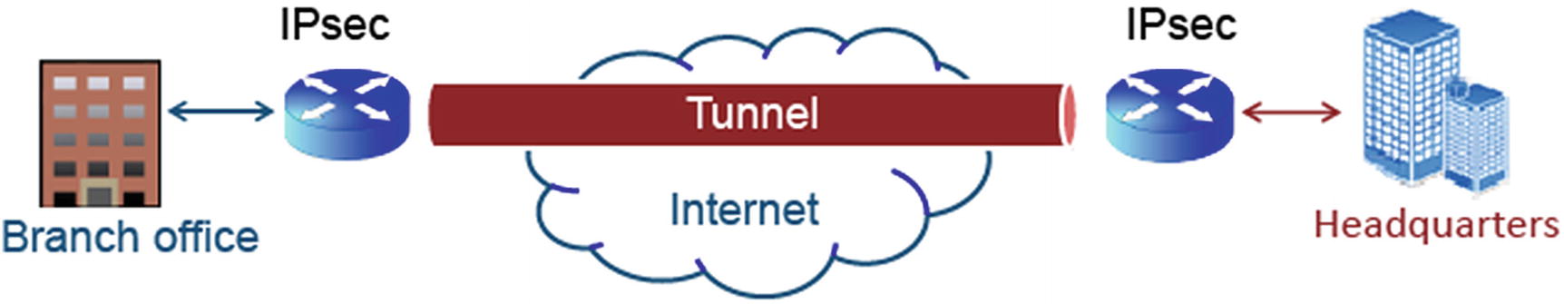
Image Illustrates How Tunneling Encapsulates Packets so That Different Protocols Can Coexist in a Single Communication Stream As Previously Described
Infrastructure Security: Securing a Workstation
Keep the operating system (OS) patched and up to date.
Remove all shares that are not necessary.
Rename the administrator account and have a strong password.
Install an antivirus program and keep it updated.
If no corporate firewall exists between the machine and the Internet, install a firewall.
Use personal firewalls if the machine has an unprotected interface to the Internet.
Turn off all services that are not needed.
Remove methods of connecting additional devices to a workstation to copy/move data.
Restrict physical access to the workstation to only approved personnel.
Virtualization

Virtualization Vulnerabilities
Include multiple operating systems to operate concurrently on the same hardware.
Provide operational flexibility.
Prevent the spread of any malware as VMs can be deleted at the end of a session.
Hubs
Hubs are devices used to interconnect network workstations in the early days of networking. The use of hubs has become somewhat obsolete with the exception of special hubs placed within a network to provide greater access to multiple ports for packet sniffing. The concept of hubs is still found in many wireless access points. Virtual hubs can be created on network switches to provide the same packet-sniffing capabilities.
Connect devices in a star configuration.
Operate at the physical layer of the OSI model.
Create a single collision domain.
It is important to be aware that hubs are insecure. All PCs connected to a hub see all of the traffic that passes through it.
Bridges
Bridges are devices that allow us to interconnect two LAN segments or collision domains. Network switches are actually multiport bridges. Wireless access points would also be considered bridging devices (see Figure 2-13).
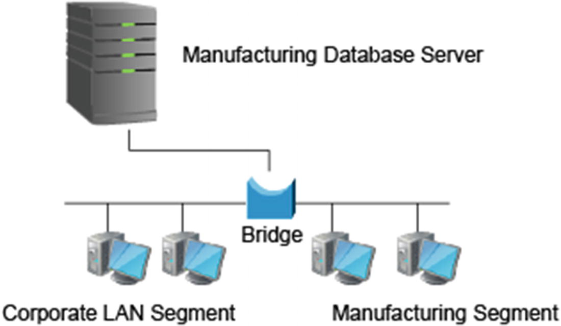
Bridges
Switches
Network switches are the most prevalent communications devices found in modern networks. They improve performance, segregate traffic, and provide a variety of advanced features that impact network security. They can operate at either the data link or network layers of the OSI model and can create separate collision domains for each port. A checklist for hardening network switches can be found on several places on the Web including the National CVE database, Cisco Systems’ website, and NIST.
A sniffer can only see traffic for the connected port.
They can be attacked due to vulnerabilities in both SNMP and Telnet.
They are subject to ARP poisoning and MAC flooding.
Routers
Routers enable us to connect one logical network to another. All corporate networks will have at least one router that is used to route traffic into and out of the organization’s network referred to as the default gateway. This design has the vulnerability of being a single point of failure. As a result, many organizations choose to use two or more routers to provide multiple paths through different carriers to the Internet. Most routers have a variety of advanced security features. Routers also come with their own vulnerabilities. Like switches, there are also checklists available for hardening network routers. Here is a quick list of important key facts.
Operate at the network layer of the OSI model.
Connect different network segments together.
Use routing protocols to determine optimal paths across a network.
Form the backbone of the Internet.
Can be attacked due to vulnerabilities in both SNMP and Telnet.
Firewalls
Most modern networks include a variety of firewalls. These devices protect the network perimeter, egress and ingress points, and the hosts on the network. Firewalls come in a variety of different forms which include stand-alone network appliances, software applications, features of operating systems, and blade or module devices that can be installed in servers or enterprise-level switches.
The function of a firewall is to control traffic coming into and out of a network. Firewalls have evolved over the years. Firewall techniques include basic packet filtering and stateful packet filtering.
Basic Packet Filtering
Checks each packet against rules predefined on the firewall
Is fairly simple, fast, and efficient
Does not detect and catch all undesired packets
Stateful Packet Filtering
Is a firewall that maintains the context of a conversation.
Is more likely to detect and catch undesired packets.
Due to overhead, network efficiency is reduced.
Modems
Modems, or modulator–demodulators, are devices that connect two network segments using different media types and communication protocols. Asynchronous modems, or phone modems, were used in the early days to connect SOHO networks to the Internet via a phone line. Synchronous modems now connect SOHO networks to the Internet via phone services (DSL), cable services, and even satellite services. Cell phones are often used today as a type of modem making the connection to the Internet through the cell phone network. Modems have several security features including MAC filtering and encryption.
Cable Modems
Uses shared cable line.
Other people can sniff traffic between the user and the ISP.
Most cable modems today also implement the Data Over Cable Service Interface Specification (DOCSIS).
DSL Modems
Uses dedicated cabling.
Traffic cannot be sniffed between the user and the ISP.
Virtual Private Networks

VPNs: Securing Communication
- 1.
VPNs are commonly used to provide a secure communication pipe across the Internet. This is accomplished by enabling the two devices to use the same encryption algorithm and keys. All traffic sent between the two devices is encrypted and therefore secure.
- 2.
VPN devices can be implemented in many different forms including network appliances, features within routers, and features of host operating systems.
- 3.
VPNs can be placed at the endpoints of the network so that traffic going from one network to another is securely known as tunnel mode or secure communications can be established from one device on a network to another device on a different network or transport mode.
- 4.
VPNs provide a high level of security; however, they pose a completely new set of vulnerabilities. When transport mode traffic is allowed to leave and enter a network, the same encryption that is protecting the data from being viewed on the Internet can prevent administrators from detecting unauthorized sensitive information entering or leaving their own network.
Intrusion Detection System

Intrusion Detection System
Mobile Devices
Can act as transmission vectors for viruses
Can be used to remove sensitive material off-site
Can be used as part of a Bluetooth attack
Media Cables
There are several types of media cables that have different uses and applications. Please read Types of Media for details on the following cable types: coaxial, UTP/STP, fiber, unguided media–infrared (IR), and unguided media–(RF)/microwave.
Security Concerns for Transmission Media

Security Concerns: Things to Avoid
Disconnection : Access to a server by an unauthorized individual
Packet Sniffing : Access to switches and routers by an unauthorized individual.
Unauthorized Access : Access to network connections by an unauthorized individual
Object Reuse
Storage media poses greater challenges and risk in modern networks. Today’s media can store far more data and be written to and read from much faster. All storage media that contains sensitive data should be controlled, monitored, and encrypted when possible. These devices should also be properly managed when they are decommissioned and no longer used.
Network-Attached Storage
Most modern networks now include mass storage devices which include NAS (network-attached storage), SAN (storage area network), and iSCSI. These technologies are devices that contain multiple hard drives and are used to store and share data with multiple devices on the network. Mass storage devices require high-speed connections, access control, and, in some cases, encryption technology.
Provides only block-based storage
Appears to the client OS as a disk visible in disk management
Provides both storage and a file system
- Appears to the client OS as a file server (client can map drives)
 Figure 2-17
Storage Area Network (SAN) and Network-Attached Storage (NAS)
Summary
It is important to have an understanding of network fundamentals needed to build network security. Be familiar with the basic network architectures and protocols which will help you to implement secure network administration principles. It will be important to use common protocols discussed in this lesson as needed to employ infrastructure security. Keep in mind the importance of what you learned about routing, and address translation which will help you further understand the vulnerabilities and threats that can be exploited.
Resources
Local Area Network: www.webopedia.com/TERM/L/local_area_network_LAN.html
Metropolitan Area Network: www.webopedia.com/TERM/M/MAN.html
Wide Area Network: www.comptia.org/content/guides/what-is-a-wide-area-network
Campus Area Network: www.webopedia.com/TERM/C/CAN.html
OSI Layers Working: https://electricalacademia.com/computer/osi-model-layers-functions/