Chapter 4
3D CAD
4.1 An introduction to 3D modelling
In Chapter 3, we discussed 2D CAD, its history and attributes. Most software programs such as AutoCAD are capable of generating 3D models from 2D CAD drawings using the ‘extrusion’ tool, while others such as 3D Studio Max can achieve similar results by altering geometric and parametric attributes of primary shapes and solids such as circles, cylinders, squares, and cubes. (Extrusion is a common term used in 2D to describe the extension of 2D CAD ‘upwards’ to reflect height.) 3D models can be any real object with three dimensions that can be displayed on a personal computer using specialised software programs.
3D modelling is applicable to a wide variety of industries. For example, the video games industry uses them to create models for video games; the medical industry, to create models of such things as internal organs; the movie industry to create characters and objects for motion pictures; the science sector uses them to create highly detailed models of chemical compounds; and the architecture industry to create models of proposed buildings, landscapes and other design elements. However, the focus of this book is on buildings.
3D architectural rendering is also an important element in the modelling process, as it helps visualisation during modelling. Photorealistic rendering, which in most software programs involves ray tracing, brings the model to life and this can be achieved using complex 3D modelling and rendering software programs. Models are rendered through specific applications into two-dimensional renders of frames. Photorealistic rendering is normally desirable when architectural visualisation is required, and can also be used in many areas such as virtual simulations and 3D worlds, demos, walkthroughs, etc. This chapter aims to depict the purpose and use of 3D modelling in the AEC/FM industry.
4.1.1 The history of 3D modelling
The art of 3D modelling in general can be traced back to late the 1800s and early 1900s. During this period, 3D clay character models were created and animated; this was referred to as claymation. Some of the first claymation stop motion movies were released with great success. Some early examples of stop motion film techniques can be seen in the The Humpty Dumpty Circus (1898), Fun in a Bakery Shop (1902), and The Haunted Hotel (1907). In the mid-twentieth century, 3D modelling attained something of a golden era in the movie industry: Arch Oboler released Bwana Devil in 1952, and Warner Bros House of Wax in 1953. However, in 1962 the first 3D CAD programs used algorithms to display 2D and 3D patterns.
In 1965, Charles Lang's team at Cambridge University's Computing Laboratory (which included Donald Welbourn and A.R. Forrest) began research into 3D-modelling CAD software. French researchers at Citroen, which included Paul de Casteljau, were able to significantly develop computations on surface geometries and complex 3D curves. Indeed, the work of de Casteljau and Bezier provided one of the foundations of 3D CAD software. However, MIT (Massachusetts Institute of Technology; S.A. Coons in 1967) and Cambridge University (A.R. Forrest, in 1968) were also very active in furthering research into the implementation of complex 3D curves and surface modelling using CAD software. In 1982, CATVIA version 1 was released as an add-on for 3D design and surface modelling (see Table 1.1) and in the late 1980s there was a large-scale introduction of computer- aided design systems (Björk and Laakso 2009)
Today's 3D modelling technology in the field of architecture or construction can be rendered to simulate reality for visualisation purposes. It also has been developed to include the fourth dimension (time). It is now possible to attach descriptive and quantitative attributes to various elements of any 3D architectural model (BIM). However, the BIM attribute of 3D will be discussed in Chapter 6.
Discussion
• What are the advantages and disadvantages of 2D CAD drafting over 2D (hand) drawings?
• What is the difference between 2D and 3D?
4.1.2 The purpose of 3D modelling
Three-dimensional (3D) modelling of buildings offers numerous benefits over 2D computer-aided drafting (CAD drafting) for AEC/FM professionals. On numerous occasions, 2D drawings of a proposed construction project prepared by the architect or designer have one aspect or another omitted; the term ‘clash detection’ is also commonly used to describe clashes of components when visualised in 3D. A well-executed 3D model makes it easier to avoid such errors and omissions.
Not only do architects gain a huge advantage in avoiding errors when putting their information into a real-world 3D environment, such advantages are also being harnessed by other industries in areas such as product development and manufacture.
The visual clarity and context coupled with the potential for reduced error has made 3D modelling a fast-growing design/presentation approach within the AEC/FM community and beyond. These models are predominantly executed using CAD software programs, which are used more frequently in developed countries. Similar to 2D (but in a more informative manner), 3D modelling can help in assisting engineers and designers in a wide variety of industries to design and manufacture products ranging from buildings, bridges, roads, aircraft, ships and cars to digital cameras, mobile phones, TVs, and clothing, etc.
Some of the key features of 3D modelling include:
• Easier visualisation processes
• Virtual simulations
• Walk-through generation
• Achieving more accurate and consistent design.
4.1.3 The advantages of 3D modelling
Modelling in 3D has numerous advantages, some of which are shared across a wide range of industries which use it. However, some advantages of 3D modelling are particular to specific industries. This section will focus on the advantages that are relevant to the AEC/FM community:
• Productivity, with the flexibility to modify designs at different levels: The majority of 3D CAD software programs enable the user to alter elements and dimensions at any stage of the modelling process without having to repeat those steps in other views. Changes made to the model are simultaneously reflected in all the available views of that particular model.
• The prototyping attribute of 3D models: 3D models are generated to represent a computer copy of the proposed real-life building or product. This makes it possible to see a building or product before it's completed.
• 3D models can also be used as marketing tools: 3D models are a tremendous marketing tool and can create additional revenue. This can be achieved by the presentation of a 3D image on a 2D surface; a walkthrough, where the client is taken into a pre-recorded walk through the building in question; or a virtual-reality interactive model, where the client is not only taken into the building but can also decide where to go or what to look at.
• Increased acceptability within the AEC/FM industry: 3D modelling has become a widely accepted technology for the design of buildings and building structures, making the process of engineering design and detailing more effective and productive when compared to 2D CAD.
• Enhanced competitiveness: 3D design gives the industry a competitive edge when bidding for different forms of design/building contracts or consultancy work, as 3D visual communication of ideas can be more persuasive in winning over a client when compared to a 2D presentation.
• Design communication: 3D models are great for design reviews as they can effectively communicate the design to other members of a design team and industry professionals connected to the project.
• Error reduction: Modelling a 3D prototype before commencing production of a building or product makes it easier to spot design errors when compared to a 2D version of the same drawing. Construction and shop fabrication drawings created from the 3D model can help ensure accuracy in the final product.
• Design variety: 3D opens up a world of design that is otherwiseinaccessible. Innovative building design cocepts can be generated digitally using 3D, which otherwise might not have been possible.
• Enhanced visual attribute: Modern CAD packages which are used for 3D modelling allow panning and rotations in three dimensions. This makes it possible to view a designed object from any chosen angle, which can also be from the inside looking out.
• Construction stage foresight: Some 3D packages allow the user to model and simulate a construction process, whereby construction errors not apparent at the design stage are identified before actual construction commences and can be easily rectified. This attribute helps to manage and minimise risk and wastage throughout all stages of a construction project. During the construction stage, 3D models also give the project management team the opportunity to view construction project information (Fischer et al. 2001). In the long run, 3D design drawings prepared by architectural engineers help the AEC/FM industry to build even safer and stronger building structures (Smith 2009).
4.1.4 The disadvantages of 3D modelling
There are fewer identifiable disadvantages of 3D modelling compared to 2D drafting. Some of the disadvantages are as follows:
• Time: 3D modelling takes longer to draw up than conventional 2D. Some CAD packages such as Sketchup have taken steps to simplify things. 3D forms are created in order to save time. Various attempts have been made by 3D software program developers to make it relatively easy to create 3D models. Despite these efforts, 3D modelling still requires a significant amount of time. It is important to point out that with an increase in the desired level of detail in a model, there is also an increase in the amount of time required to execute that particular model.
• Training: Modelling in 3D also requires training, which sometimes can be expensive. There are numerous CAD modelling packages, and methods of 3D object creation and modification might differ from one package to another. For example, the surface modelling approach is slightly different from solid modelling; however, a single 3D CAD program such as AutoCAD can support both approaches.
• Interoperability: The exchange of information between allied industry professionals can be reduced if editable 3D files cannot be exchanged effectively. The level of interoperability among 3D packages is limited. The key, industry-standard 3D software programs such as AutoCAD 3D, 3D Studio Max and Sketchup are limited in terms of the number of other 3D programs they can share files with. For example, AutoCAD 3D has made it such that there is interoperability between its 3D files and Microstation DGN files. In some cases, AutoCAD 3D allows interoperability at 2D level with the exchange of 2D line data but not with 3D solid, surface and wireframe data: an example of such a program is SYCODE, where steps are being taken to address this problem in their Alibre Design. The move to address and improve the interoperability between programs is currently a lot more focused on BIM-capable 3D CAD programs using the IFC (Industry Foundation Class) standards.
4.2 3D modelling principles
Before commencing on a 3D modelling exercise in a CAD environment, there are some important principles which will ultimately lead to the production of a successful 3D model. It is also important to point out that some of these principles should be observed in a particular sequence while some can be applied at any time or even at a later stage in the drawing process. These principles include:
• Realism: A 3D model should be based on real-life references. When modelling a building, a 3D representation of a sash window should have taken its reference from a real-life sash window, based on its components, texture, geometry and even its mode of operation. Without such a reference to reality, a modelled sash window could end up looking like something very different from the impression the user intends to convey.
• Scale and proportion: The size and structure of objects and their relationship with one another should reflect proportions based on reality. It is possible, however, to have a particular type of object existing in reality at a different scale and only separated by functionality. An example might be where you are modelling a doll's house versus a real house. A doll's house could then be portrayed as a doll's house, but would be uninhabitable when placed within the context of other appropriately scaled objects such as people, trees, etc.
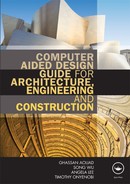
• Volume: The volume element is what gives a model its third-dimensional attribute. While the majority of objects can be broken down into primitive 3D volumes, there are other volumes which are asymmetrical and irregular. During the initial modelling phase, these 3D primitives can be reduced to polymeshes or placeholder models. In some CAD programs such as AutoCAD and Sketchup 3D volumes can be created by extrusion of 2D regular or irregular shapes along the z axis; this creates 3D volumes with a footprint of the original shape. Provision is usually made for the extrusion to be tapered or simply follow a predefined path. The sphere volume, however, is different from the other basic forms; with no straight lines, it cannot be generated by simple extrusion. The sphere pre-exists in most 3D CAD programs as 3D mesh which can be resized and deformed (see Figure 4.1).
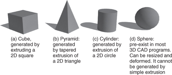
Figure 4.1 3D Primitive volumes used during 3D CAD modelling.
• Appeal: A 3D model should be able to communicate the design concept in terms of the elements and principles of design inherent in the building in question. If a designer incorporates elements to convey certain emotions or impressions in a building design, it is important that such information/mood is communicated in the final 3D model. The finished model should have a level of appeal. This can be achieved by good use of lines, shapes, colours, etc.
• Exaggeration: Sometimes the finished 3D model might, to a degree, fail to communicate the intended idea effectively. In such a circumstance, some features or rendering are exaggerated. The act of exaggeration might be applicable for 3D movies but should be discouraged for technical or parametric building models as this will communicate inaccurate design information.
• Detail: During a 3D-modelling exercise, paying attention to details make the objects richer, more interesting and more appealing. It is advisable to use references to discover what details might communicate and enrich your model. Catalogues of specified elements for a building can reveal significant information on desirable details which might be difficult to observe in a 2D drawing.
• Texturing/surface treatment: In reality the majority of surfaces have one form of texture or the other. With different surface types the chances are that you also have different texture types. In a building, the surface texture of a wall is different from that of the floor (depending on the choice of floor finish). While generating a 3D model, it isimportant that the surface treatment with respectto the choice of texture corresponds to the design specification issued by the designer. Texturescaling is an important part of texture editing. When a texture file is scaled too large or too small, it loses its desired identity on the model when it is applied and this error can affect the visual quality of the model. The closer the selectedtexture is to reality, the higher chances of a high-quality model.
• Appropriate light and shade: This is an important principle to adhere to during 3D modelling as inconsistent light and shade on an object relative to the light source can eliminate to a large degree the realistic quality of the model. Where 3D texture surfaces are captured under controlled illumination conditions, the selected texture works in combination with the available lighting to enhance a model aesthetically. Most CAD programs are designed to provide accurate light and shade conditions with changes in the light source and type.
• Coordinate systems: Knowledge of the coordinate systems is crucial to 3D modelling because this is what separates 3D modelling from 2D drafting. Along the horizontal plane there are two main axes, x and y. The x, y axes, which are two dimensional, can be referred to a representation where ‘depth’ is absent. However, with the introduction of the ‘z’ axis depth is introduced and modelling rather than drafting is required to execute the design. The x, y, z coordinates can be rotated in multiple directions when viewing different sides of the object being modelled and can help the modeller to identify complex object faces during modelling.
• Functionality: In a 3D modelling exercise, it is important that all elements of an object being modelled, even roofs, facades or false accoutrements, should appear to have a purpose or function even if the function is that of decoration. This helps create the illusion of realism and a sense of interest about the object that makes it appealing.
4.2.1 Modelling
Having discussed the principles of 3D modelling it is important to note that 3D model reconstruction approaches can be either in the form of solid modelling and/or surface modelling. As the name implies, a solid model is a digital representation of a 3D object with a defined volume (see Section 4.2.1.1). A surface model, on the other hand, lays emphasis on modelling using digital surfaces to form any desired 3D objects or planes (see Section 4.2.1.2).
4.2.1.1 Solid modelling
Solid models define the volume of the object they represent (like a rock). These are more realistic, but more difficult to build. Solid modelling is distinguished from other areas in geometric modelling and computing by its emphasis on informational completeness, physical fidelity and universality (Shapiro, 2001).
Solid modelling is particularly apt for computer-aided modelling (CAM) systems which support solid modelling. This is because there are no gaps between the faces of solid models as the model has to be ‘watertight’. Manufacturing software goes through painstakingly difficult mathematical functions to determine what to do if there are gaps in a surface model and to make sure the object it creates doesn't gouge (Hohler, 2000). Solid models allow for interference checking, which tests seeing if two or more objects occupy the same space.
Solid modelling is a three-dimensional modelling process in which solid characteristics of an object are built into the database so that complex internal structures can be realistically represented. (Shapiro, 2001).
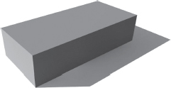
Figure 4.2 Solid model showing an extruded rectangle
The real power of a solid modelling application is how it can take the solid objects and combine them together by intersecting, joining or subtracting the objects from one another to create the desired resulting shapes. Because everything in a solid model design is a ‘watertight’ model of the part, the solid modeller is able to know the topology of the entire model. By topology we mean that it knows what faces are adjacent to each other and which edges are tangent (Hohler, 2000).
Most solid modelling programs support geometric constraint which is a relationship of an entity to other entities. When one or more entities are ‘constrained’ to each other, changing any of the entities will most likely have an effect on the others. For example, in a 3D solid model, changing one dimension can affect the entire solid as they are quickly updated (in most solid modelling programs).
Some of the benefits of solid modelling include: (i) it is easy to learn/use, (ii) it possesses parametric/associative capabilities, (iii) it provides quicker creation and updating of assemblies, and (iv) it is excellent for creating functional models.
4.2.1.2 Surface modelling
These models represent the surface, e.g. the boundary of the object, not its volume (like an infinitesimally thin flexible paper). Surface models are easier to work with than solid models. Almost all visual models used in games and movies are shell models.
REGULAR SURFACE MODELLING
Surfaces can be created from curves, surface primitives or from multiple surfaces using 3D CAD software programs. This type of modelling approach is used to represent simple geometric forms with rigid dimensions such as planes, cylinders and conic surfaces. In the construction industry, the majority of buildings have surfaces which fall into this category. As a result, the majority of 3D CAD programs provide numerous tools which make it easy to generate this type of surface, such as the extrusion tool.
FREEFORM/NURB SURFACE MODELLING
NURBS (Nonuniform Rational B-Spline) is a modelling approach which involves freeform surfaces which are freely deformed and sculpted by pulling or pushing what is referred to as ‘control points’ (see Figure 4.3). Development of NURBS began in the 1950s by engineers who were in need of a mathematically precise representation of freeform surfaces like those used for aerodynamic cars.
A freeform surface is used in CAD and other computer graphics software to describe the skin of a 3D geometric element. Unlike regular surface, freeform surfaces do not have rigid radial dimensions due to the irregularity of the surfaces. Freeform surfaces are defined by their control points, between patches and number of patches. The control points (known as poles) of a surface define its shape and control polygons work together with control points for surface editing (see Figure 4.3).
SURFACE MODELLING SOFTWARE
Software programs that have surface modelling capabilities must have enough tools within the software to completely define any feature on surfaces being modelled. Such surface modelling software programs should:
• Provide enough tools to completely define any feature on surfaces being modelled.
• Have numerous functions for defining the different shapes of regular or freeform surfaces including ruled, revolved, lofted, extruded, swept, offset, filleted, blended and planar boundary.
• Support functions such as surface trimming, extending, intersecting, projecting, polygon tessellation, coordinate-system transformations and editing.
• Allow extraction of surface data such as flow curves, vectors and planes, among other functions.
• Have a set of tools for defining points, planes, vectors and splines used with surface modelling. Most surface creation functions need user inputs to define surfaces.
Figure 4.3 Surface model showing (i) patches/NURB surfaces, (ii) control points/poles and (iii) a control polygon.
4.3 Creating a 3D model
3D models can be created using surface or solid modelling approaches. In order to create any 3D model, it is important the purpose of the model is established. A 3D model which is required for CAM purposes will be better created as a solid model and not surface for reasons outlined in section 4.2.1.1. However, if the purpose of the model is solely for visualisation, surface models would be preferable as they are relatively lighter in terms of required computer capacity. As a result, surface modelling of a particular object are less likely to slow down your computer as compared to that of solid models of same object.
In order to create a 3D model, some key steps illustrated in section 2.2.1 which focused on 2D drafting need to be followed. Some of the relatively generic initial steps for most 3D software programs include: file creation, drawing unit assignments, drawing grid creation, and layering. Creating 3D models include: creating 3D objects from 2D shapes; navigating in 3D space; modifying and shaping 3D objects; and rendering objects.
It is important to mention that the illustrations below are generic and it is advised that the tutorials of any particular software being used should be consulted for specific instructions.
After the initial steps have been executed, the following steps outlined in Sections 4.3.1 to 4.3.4 are taken to proceed with creating a 3D model.
4.3.1 Creating 3D objects from 2D shapes
CREATION OF A BASIC 2D SHAPE
Basic 2D shapes are the shapes which act as the first step to producing the desired 3D object. Regular shapes such as circles, squares, rectangles, polygons can be drawn on a 2D plane. Most 3D software programs have standard tools which can generate these regular shapes such as circle tool, rectangle tool, etc.
FURTHER EDITING OF THE SHAPE TO A 2D FOOTPRINT OF THE DESIRED BASIC 3D FORM
These shapes need to closely resemble the footprints of the intended 3D object such as a wall etc. In some cases the desired footprints might have irregular appearances. As a result, further editing of the shape is needed. Sometimes a flexible line tool (polyline) can be used to create the irregular 2D shapes from scratch before extruding to 3D.
EXTRUSION OF A 2D SHAPE TO CREATE A 3D OBJECT
In order to create a 3D object from a 2D shape, it is possible to extrude the 2D shape along the vertical, curved path or at an angle. In this instance, a path in the form of a vertical line, curved arc, or line at an angle is created to guide the extrusion; this is the case with 3D software programs such as AutoCAD and Sketchup (see Figure 4.4).
To carry out the extrusion task described above, click on the appropriate (extrusion) tool in the software being used and follow the instructions provided by the software tutorial to complete the extrusion task. However, for software programs such as AutoCAD, you will need to click the ‘extrusion’ tool then following the instructions on the command line (this is a text window where you are allowed to type commands and view instructions in the AutoCAD software).
You will then be required to click the edited 2D shape you have created after which you will need to type the desired height and specify the path (if required) in the command line. On pressing ‘enter’ or clicking any OK button in the software being used, the 3D object is formed. The extrusion can also be carried out manually without entering dimensions. It is important to note that some software programs might have different names for the extrusion tool.
4.3.2 Navigating in 3D space
When working on a 3D project in a 3D space, there is a need to be able to observe the creation or modification of a model from different angles or views simultaneously. This is achieved by dividing the work area into multiple little work areas (viewports) showing different views of the model simultaneously.
There is also a need to move from one part of the model being generated to another part of it in order to either create an element or modify an element in the model. Sometimes it might be important to move closer to the element (zoom in) in order to accurately execute the creation or modification or move further away from the model (zoom out) in order to have a fuller view of what is being modelled. Sometimes you also might want to move the model from side to side without actually moving in or out (pan), or even rotate the model freely in the 3D space (orbit). All the above mentioned actions can be referred to as navigating in 3D space.
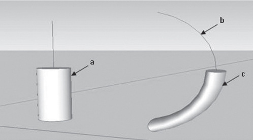
Figure 4.4 Extrusion of a circle vertically and along an arc using Sketchup:
(a) cylinder extruded vertically from a circle shape; (b) an arc which provided a path/guide for the extrusion of a circle shape;(c) extruded circle shape along the arc path ‘b’.
VIEWPORT
While working on a 3D object using a 3D software program, it is important to create multiple viewports to be able to view the work area from different angles simultaneously. The term ‘viewport’ is used to describe the number of subdivisions within the work area. These subdivisions can come in different arrangements. For example, the work area can be single and undivided (1 viewport), or it can be divided into two halves (2 viewports), or divided into three (3 viewports) or even four (4 viewports) and so on. See an example of 4 equal viewports in Figure 4.5 (a) and 4.5 (b) (view-ports 1 to 4 for Maya and AutoCAD LT software programs respectively). The maximum number of possible subdivisions and the arrangement of these subdivisions will depend on the software program being used.
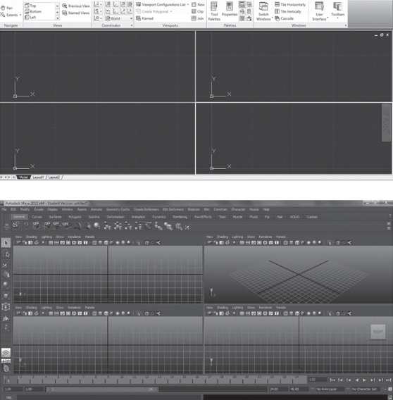
Figure 4.5 Four viewports with equal subdivision of work area. Viewports labelled from ‘viewport 1 to viewport 4’: (a) four viewports from AutoCADLT; (b) four viewport from Maya.
The term ‘viewport’ is used in AutoCAD and a few other software programs, but different names could be used to describe it depending on the program being used.
Some 3D software programs such as 3D Studio Max have four viewports available at start-up while in most cases AutoCAD has a single viewport opened at start-up. Other software programs with viewports are AutoCAD LT (for 2D) (see Figure 4.5 (a)), full AutoCAD (for 2D and 3D), and Maya (for 3D) (see Figure 4.5 (b)).
ZOOM
While working on an object in 3D it is important to simultaneously observe changes made to the object from different angles. This helps for a quicker and more accurate modelling process and multiple viewports help to achieve this.
The zoom tool is an important tool for both 2D and 3D. This tool helps enlarge the desired area of interest on the 3D object (zoom in) or reduces the object to have a wider view of the work area (zoom out). This tool is often used when attending to details or smaller parts of the object by making them large enough for editing.
PAN
While working on a particular 3D project, there are instances when the user needs to maintain the zoom level of the work area but at the same time needs to see portions of the object outside the view area. Under such circumstances, using the ‘pan’ tool will move the drawing area in the direction of the pan without adjusting the zoom level.
ORBIT
The ‘orbit’ tool is a 3D viewing tool which is referred to as such in AutoCAD. It represents your orientation in 3D space. By moving the orbit tool, you move the entire model along the x, y and z axes. This can be used to view the model during the modelling exercise. However, other 3D software programs have different names for this tool (refer to the tutorial manual of the software program being used).
4.3.3 Modifying and shaping 3D objects
A 3D object can be edited or modified until the final desired object is achieved. For example a cube in 3D can be modified and shaped to a pyramid. Methods of editing an original will depend on the nature of the 3D object: is it a solid model or a surface model?
A 3D object created as a result of solid modelling is modified slightly differently to those generated using NURBS. A NURBS surface model made up of patches can be modified by adjusting the control points (see Figure 4.3). A solid model can be modified primarily by subtraction or addition of other 3D objects. A solid model can also be modified by slicing off unwanted parts of the model.
EDITING OF A BASIC 3D FORM TO THE DESIRED 3D FORM
3D solid objects can be modified by the addition and subtraction of other objects to create the desired final object.
To carry out a subtraction exercise, the primary object (the object from which something is to be subtracted) is identified. A secondary object is created with the geometry of the part to be inserted identical to the geometry of the hollow intended to be created on the primary object.
The secondary object is then placed in the position on the primary object in the area where the hollow is to be made. The appropriate subtraction command is then given depending on the software program being used. The secondary object then disappears, leaving a hollow on the primary object identical in geometry to the part of the secondary object inserted. This method can be used to create windows for example.
To carry out an addition exercise, the same procedure is followed for both the primary and secondary objects. However, this time attention is paid to the geometry of the secondary object that is to be added. During the addition process both the primary and secondary objects are joined.
Some 3D software programs make provisions for a solid model to be sliced. This task is similar to using a knife to slice through butter. The task of slicing takes place digitally and the software allows you to (i) create your knife element or ‘cutting edge’, (ii) position the cutting edge in the desired position on the object to be sliced, and (ii) execute the slicing task by selecting the part of the element that should remain or the part that needs to be removed (this depends on the software program).
It is important to point out that the type of command, sequence of commands or entire editing approach might differ with different programs, so it is important to consult the tutorial of the 3D software program being used.
4.3.4 Rendering objects
Rendering of 3D models helps viewers appreciate what the model represents, when colours, textures and lighting on the object are used appropriately. The rendering of modelled objects is key if visualisation is one of the intended objectives of the model.
TEXTURING AND RENDERING
There are different levels of rendering and the type of rendering adopted will depend on the purpose and target viewers of the model. Simple rendering is basic, less realistic, less demanding on the computer and quicker to execute. However, photo-realistic or more complex rendering is more informative, closer to reality and takes longer to execute. Sometimes wireframe rendering can be used and this is where the model is reduced to a series of lines or wires.
3D software programs make provision within the software for the user to render the model after creating it. However, some 3D software programs make provision for the use of a different rendering software programs to handle the rendering task. The rendering software can be embedded into the parent 3D software as a ‘plug-in’ or exist as separate software, a ‘stand alone’. For example ArchiCAD as the parent 3D software uses Atlantis as the rendering software for its models, while Sketchup as the parent 3D software uses Podium as the rendering software. The list is endless.
Rendering in 3D is a simple process but inputting settings such as lighting, shaows, resolution, etc., can be relatively complex and this can vary between rendering software programs. In most 3D software programs, the desired rendering resolution can affect the rendering time from a matter of minutes to a matter of days. However, high speed computers can provide some reduction in rendering time.
To achieve photorealistic rendering, it is important that the modeller is competent with regards to the software program being used. The model should be ready before the commencement of rendering. Select materials from the material library provided in the software or online.
Scale materials appropriately such that patterns on the materials are as close to reality as possible in terms of colour and dimensions. Ensure that reflection and transparency values have been appropriately assigned. It is important to note that opaque objects like wooden floors have a level of reflection and hence this should be taken into account while rendering.
While applying the lighting element to the object to be rendered, a decision is made as to whether day lighting or artificial lighting is to be used. Values are entered for the intensity of the lights, which in most cases are updated in the work area. If artificial lights are used, light fixtures should be positioned appropriately. While assigning values for artificial lighting, ‘hot spots’ (portions of very high illumination on a surface) should be avoided.
The camera positions and target views should be identified in order to render the desired area of the object. When this is done, the rendering process can commence. The illustration in this section is generic as some software programs can be more complex. Please refer to relevant tutorials.
WIREFRAME RENDERING
During the modelling exercise, it is possible to render in wireframe as opposed to photorealistic approach. A wireframe model is the result of a rendering process which creates a visual presentation of a 3D object as being defined by multiple lines or curves. It is created by connecting an object's constituent vertices using these straight lines or curves.
Wireframe rendering of a 3D model allows the visualisation of its underlying design structure. The wireframe model in some instances can appear complex if there are multiple underlying structures within the model. This can sometimes make the complex wire network difficult to articulate. Curved objects are more likely to generate more lines or curves (cylinders and spheres) than objects with linear edges or planes (cubes and pyramids) (see Figure 4.6).
The wireframe model, however, has the advantage of being light in the sense that less computer processing power is required to manipulate the model in comparison to the other rendering approaches.
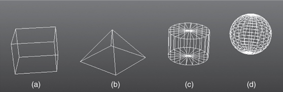
Figure 4.6 Wireframe rendering of (a) cube, (b) pyramid, (c), cylinder, and (d) sphere.
4.4 3D modelling practical examples
Some examples of 3D modelling are demonstrated in the following sections. Solid and surface modelling approaches can be employed; however, this depends on the purpose of the model. Hybrid solid and surface modelling can also be used for relatively complex models.
4.4.1 Example 1: Surface modelling
Different 3D software programs provide different ways of creating surface models. In previous versions of AutoCAD, surface models can be created by drawing a polyline and assigning thickness 0 to the polyline. The value assigned results in a form of extrusion of that line along the vertical axis.
Other software programs such as Sketchup provides an interactive and flexible approach. Shape tools such as the ‘rectangle’ or ‘circle’ tools can be used to create an initial 2D shape. A ‘push/pull’ tool is then used to drag the 2D shape vertically to create a 3D surface model in a form of extrusion. Values such as height can be assigned rather than the vertical drag.
4.4.2 Example 2: 3D solid modelling
As solid modelling involves defining an object with geometric mass, solid modelling programs usually create models by creating a base or primary solid and adding to or subtracting from it. They can be modified using features such as extrudes, extrude cuts, revolves, radii, chamfers, etc. (Finkle, 2011). See Section 4.3.3.
4.4.3 Example 3: Modelling a simple house
In this example, Sketchup 7 was used to produce a simple 3D model of the outer shell of a house. For more complex 3D models, a detailed floor plan layout generated in the 3D program being used or in another program forms the footprint for the model.
Step 1: The 2D rectangular boundary ‘a’, which represents the footprint of the intended 3D model, is generated in the Sketchup software (see Figure 4.5 (a)). The shape of the footprint generated must not be a rectangle as this will depend on the footprint and overall geometry of the intended model. However, the polyline must form a closed boundary, i.e. the start and end point of the line used to create the shape of the footprint must meet.
The perimeter walls are generated by drawing an inner rectangle ‘b’ (see Figure 4.5 (b)). The thickness of the wall is determined by the user or designer. At this stage the steps are carried out in a 2D plane, i.e. along the x and y axes.
Step 2: With the inner rectangle which marks out the perimeter wall in place, the inner segment (rectangle footprint) ‘b’ and outer segment (perimeter wall footprint) ‘c’ are now separate entities.
With this separation in place the segment (perimeter wall footprint) ‘c’ is then pulled up to the desired height using the ‘push/pull’ tool (see Figure 4.6 (a)). This height can be prescribed by entering the desired values in the relevant box within the Sketchup program interface.
A similar process is repeated without the inner rectangle to create a larger rectangle ‘l’ for fascia/roof representations (see Figure 4.6 (b)). The rectangle plane, however, was created with slightly larger length and width dimensions to make provision for the eaves, and pushed up to create the fascia ‘f’.
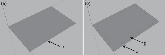
Figure4.7 (a) 2D rectangular boundary (perimeter wall footprint); (b) inner rectangle showing wallthickness.
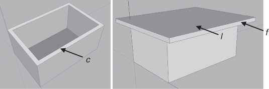
Figure 4.8 (a) Rectangular boundary/perimeter wall extruded/pulled up; (b) larger rectangle for fascia/roof representations added on top of wall.
Step 3: The next step is to create a gable roof. In order to achieve this, it was important that the upper rectangle ‘l’ be divided in the middle to provide a handle with which to raise the gable roof. The gable roof pitch was raised from the handle using the Sketchup ‘move’ tool.
With the roof in place, a similar exercise as ‘step 1’ was carried out to mark out the door ‘d’ and window ‘w’ openings. Rather than pull, the ‘push pull’ tool was used this time to push the marked door rectangle and the marked window rectangle, which were then separate segments (see Figure 4.7 (a)). Openings were hence created on the wall to provide for two windows and a door (see Figure 4.7 (b)).
Attention was then given to the door and window frame representations by using similar approaches to those described above. However, to create the frames, the exercise was carried out on a smaller scale.
Step 4: On completion of the modelling stage, the final step involved material assignment and rendering.
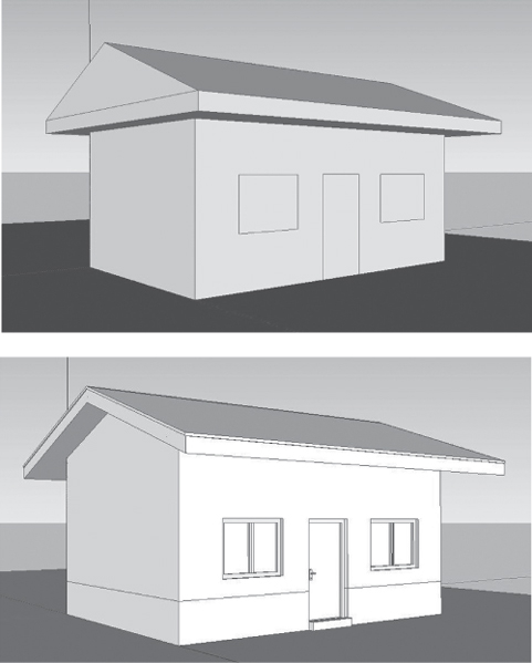
Figure 4.9 (a) 3D model with walls and roof in place with outline of door and windows; (b) further details of roof door and window added.
The rendering exercise has been generically described in Section 4.3.4. Materials were selected from the material library provided by the Sketchup software. The materials used (brick, wood and roof tiles) were scaled appropriately with patterns as close to reality as possible in terms of colour and dimensions and then applied (see Figure 4.10 (a)).
Basic lighting was applied to the 3D image. The finished model was then rendered using Sketchup plug-in render software (Podium) to create a 3D image (see Figure 4.10 (b)).
The above example has been simplified. In some programs, and for more complex buildings, further steps not mentioned above may be needed. However, the above example provides an overview on the key steps required for 3D modelling.
4.5 Summary
In this chapter, we have established that three-dimensional (3D) modelling of buildings offers numerous benefits over 2D computer-aided drafting (CAD drafting) for AEC/FM professionals.
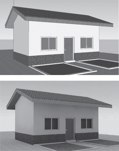
Figure 4.10 (a) Complete 3D model with materials assigned but without rendering; (b) rendered complete 3D model.
Modelling in 3D has numerous advantages, some of which are shared across a wide range of industries which use 3D to reduce errors and communicate designs with enhanced visual attributes, etc. However, some advantages of 3D modelling are peculiar to specific industries, such as the construction industry where foresight, though appreciated by stakeholders, is critical to contractors. There are fewer identifiable disadvantages of 3D modelling compared to 2D drafting.
There are certain principles to consider while modelling in 3D. These principles should be observed in a particular sequence while some can be applied at any time or even at a later stage in the drawing process. These principles involve realism, scale, volume, etc. (see Section 4.2).
The modelling approach can either be solid modelling or surface modelling. Either one of them have areas where they can be best applied. Irrespective of the modelling approach, solid or surface, there are fundamental steps to take while modelling in 3D, which have been discussed in Section 4.3.
It is also important to remember that different 3D CAD drafting programs might have slightly different ways of achieving the different steps listed in Section 4.3 but the fundamental concepts are predominantly similar.