
12
PORTABLE DIMMING AND DISTRIBUTION SYSTEMS
Late in the 1960s, when I started working for a lighting manufacturer, I was told, “We sell what we have. We don't encourage the customer to ask for specials.”
That remained true into the 1980s. Like legitimate theatre, concert lighting borrowed from any market or service that had something that could be adopted, modified, or used to its benefit.
By the mid-1980s, though, things were changing. New manufacturers were trying to meet the needs of concert and touring lighting. Products appeared that were not adaptations or reworkings of old ideas but instead were exciting new products cut from the whole cloth of a new vision.
Dimming is the area where packaging, not electronic innovation, made the first real impact in the early years of touring. In the 1970s, the established manufacturers were just beginning to market compact groups of 6 to 12 dimmers in a portable unit, usually a 19-inch rack-mount configuration. What the manufacturers did not think of was mounting input connections as well as output strips directly to the dimmer packs so there would be much less to assemble each time the dimmers were set up.
Distribution systems with low voltage control patching were a true touring innovation initiated largely by British manufacturers. This design allowed designers to assign one or more dimmers to a single control channel on the console. Later, electronic or soft patch systems appeared that used the lighting console's computer to assign these control circuits. Some British and U.S. manufacturers put a “mini-pin” cord-type patch bay into their dimmer racks (Figure 12.1).
Another way to assign luminaires to a dimmer was to make panels with more than one female connector. The electrician could simply place the appropriate cable's male connector into the dimmer rack's female connector and, assuming here is control of the dimmer, one or more luminaires could be energized at different locations by the same dimmer. if there is an internal low voltage patching system in the dimmer rack or a soft patch in the console, it is possible to make the connection between the luminaires and the dimmers assignable while using Socapex 6 circuit connectors, without the need to connect each individual pin connector.
The placing of several of these package dimmers (Figure 12.2) in a single, castered, road case meant that 24 to 72 1-kW or 2.4-kW dimmers could
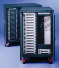
FIGURE 12.1 ETC 48-channel road rack with mini-pin patch bay. (Photograph by Electronic Theatre Controls, Inc.)
be connected and ready to operate in a fraction of the time it would take to stack and wire each pack individually. Figure 12.1 shows the front view of an Electronic Theatre Controls (ETC) rack equipped with casters and 24 double modules (48 2.4-kW dimmers), with 3 spare modules (lower right). The electronic brains are at the top, and a mini-pin patch cord panel that facilitates output assignment is on the right. Shipping damage is considerably reduced by the use of slide-in wooden covers to protect the front and back during transit. In the early dimmers, it was necessary to take the packs apart to add lock washers and epoxy to keep the components from rattling to pieces in the truck. But, here again, the wise manufacturer listened and quickly made the components more secure. The most popular dimmer racks used on the road were those that used a modular construction of one or two dimmers in a slide-out track for quick and easy replacement. A concert setup goes too fast for a technician to shut down an entire rack to disassemble it to get at one dimmer, and then it is very difficult to find the problem and replace the component. With modules, a spare can be shoved in and when time allows the bad unit tested and repaired. Recently, new dimmer packs have been introduced by several manufacturers that are only semimodular, because the dimmers have become so reliable that the added cost and space required for a modular design have been eliminated (Figure 12.3).
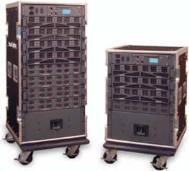
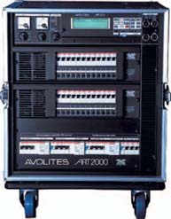
FIGURE 12.3 Avolites Art dimmer rack. (Photograph by Avolite.)
In the early days, before touring gained a foothold, U.S. dimmer modules were offered in a wide range of capacities: 2 kW, 2.4 kW, 3.6 kW, 4 kW, 6 kW, and even 12 kW. However, these were bulky and very heavy, as they were designed for installations where weight was not an important criterion. A big advance came when British manufacturers utilized small 1-kW dimmers. While these were not true modules that could be easily removed from the rack, the road crews liked them because they were more compact, and the lighting designers liked them because they gave them individual control of each luminaire. This design allowed each PAR-64 (99% of all the luminaires on the road were 1000 watts at that time) to be patched without twofers or multiple outlets. Now the low-voltage patch could take over and assign the dimmer and associated luminaire to any one or more control channels. The 1-kW dimmer also meant that more circuits could be housed in a single, movable rack with the main circuit breakers fully enclosed in a protected unit. American manufacturers such as ETC went with 2.4-kW modules. Today, you will find people that are fans of either for their own reasons, but both clearly have balanced shares of the market.
The evolution to true road status meant that a number of things had to become integrated into the same case. The first was the power distribution system, although there are still reasons to carry separate main breakers designed to distribute power to multiple dimmers and power racks, and they are certainly available for special needs. After trying out a number of connectors, the U.S. touring industry settled on the Cam-Lok1 “J” Power series, which is used exclusively on the industry's standard feeder sizes: #2/0 and #4/0 single-line feeders. These single feeder cables are color coded to a universal standard so neutral, ground, and hot legs are readily apparent to electricians making the connections (Figure 12.4). These feeder sizes were chosen because most house disconnects are either 200 or 400 amp (per leg), which matched very well. They are rated for 225 amps and 400 amps, respectively. To work the simple math, that means a 200-amp service can safely run 42 1.2-kW dimmers; however, a PAR-64 is most often used with a 1000-watt lamp, which translates into 8.3 amps, so we can safely run 48 1-kW dimmers on this feeder. The same goes for the #4/0 and 96 1-kW dimmers. Some of the racks have a power feed-through system, so a 48-channel 1-kW rack can feed onto another without establishing a “home run” for the second rack.
The next addition was digital multiplexed (DMX) capacity. The Engineering Technical Committee of the United States Institute for Theatre Technology (USITT) drew up the standard we still use today, DMX-512. One of the features of DMX compared to analog is that 512 channels can be controlled with one cable instead of running a cable to each dimmer rack. Low-voltage analog requires a control wire for each dimmer, resulting in a large bundle of wires. As the number of dimmers increased, it became more difficult to build control cables that were flexible enough for portable situations. Now all that is about to change (see Chapter 20), and the new system will give us the capacity for many more channels to handle moving luminaires, scrollers, and LEDs.
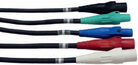
FIGURE 12.4 Cam-Lok “J”series connector color coded for U.S. hot, neutral, and ground. (Photograph by CBI Cables.)
Another standardized item that speeds assembly of dimming and luminaires is multicable. A 6-circuit version is the most popular; however there is also a 12-channel version. The Socapex beat the competition, and now all rental and road houses are standardized to this connection. It provides a quick, secure connection between the dimmer rack and the raceway or “break-out.” Most dimmer racks provide some indication of power connection and a main breaker to protect the unit. Some even have digital meters that show voltage and the amperage being consumed.
Another push has been into high-density dimming. Because the big manufacturers were behind in the total packaging of dimmers with ancillary gear, they began to focus on the research and development of miniaturized components; however, the concert field is still dominated by newer start-up companies that were not around in the 1970s. Dimmers that provide fully integrated systems in a road case, complete with main breaker and multicable connections, are available from some old-line companies, but ETC still holds a commanding lead in this area. The initial dominance by British manufacturers was mainly due to their direct involvement in touring and seeing firsthand what worked for the road. Eventually, they got a major piece of the installation business which probably has led to the demise of most of the old-line companies.
The newest dimmers today use sine-wave technology, which effectively eliminates hum in the lamp filament. This is generally not an issue for concerts, but in sales to theatres and television studios this is an important consideration. Naturally, these dimmers cost more.
The most popular racks in the United States are ETC Sensor racks configured with 48 2.4-kW dimmers. There are several strong contenders; for example, Avolite, Strand Lighting, LightRack, and Celco's Fusion series use 10-amp dimmers. (Note: The Fusion racks use groups of 12 dimmers in each module.) The reliability of the ETC Sensor dimmers has been tested over many years, and touring folk tend to stay with what they know is reliable (see Figure 12.5).
POWER DISTRIBUTION RACKS
Fairly new to the market is the addition of racks that simply distribute power, not dimming, due to the use of moving luminaires that use HMI or other “shortarc” lamps. Most, but not all, moving luminaires use short-arc or Mercury (Hg) medium-arc iodide (HMI) and HTI lamps that cannot be dimmed. These power distribution racks have also addressed the need for separate power sources for 120-, 208-, and 240-volt lamps; it is not uncommon for a lighting rig to have all three types of lamps in the moving luminaire package. A popular rack is the Lex Products Fuzzy Touring rack (Figure 12.6), which has 72 1.5-kW circuits. Motion Laboratories manufactures connector and breaker arrangements that can be configured for 110-volt, single-phase power; 125/250- and 120/208-volt, three-phase Y power; and 208-volt, three-phase power. The Leprecon touring rack systems are offered in various sizes and configurations; these power panels are efficient in providing the exact power needed for sophisticated luminaires.
OTHER POWER DISTRIBUTION
Many shows now require a multitude of power sources for computers, video projection, etc. These needs are handled via break-out boxes (Figure 12.7)
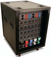
FIGURE 12.6 Power distribution rack.( Photograph by Lex Products Corp.)
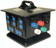
FIGURE 12.7 Power break-out box.( Photograph by LEX Products Corp.)
set near a cluster of 120-volt power needs. Power distribution racks or break-out boxes should not be powered via pass-through Cam-Lok sets from the dimmer rack, as frequency issues can arise from the
electronics in the silicon-controlled rectifier (SCR) dimmers, which can cause frequency harmonic problems with computers and other sources. (See Figure 12.8.) Sine-wave dimmer technology may eliminate this issue but I have not personally tested them for this issue.
MULTICABLE
Today's multicable has been standardized so rental and touring suppliers can match needs on bigger shows or specials. The standard connection is the Socapex SL61 in several outer case versions (Figure 12.9). It was first introduced to touring by Showlites in the early 1970s. It comes in two internal connection configuations; solder or crimp the standard cable using a flexible S/O jacket of 12-AWG gauge wire inside the outer covering, which can handle 25 amps. The wiring inside the shell includes separate wires for each hot, neutral, and ground for every circuit, which leaves the last connection, dead center, as a spare. The method of connection to the dimmer rack or a break-out or break-in is via a key-way and threaded collar that has a defined number of turns and lock. This is an excellent system that has been road tested and proven safe for many years. The terms break-in and break-out refer to Socapex connectors, either male or female (as required), split into 6 individual cables of SJO 12/3-gauge cables, each with standard theatrical 20-amp pin connectors or 1-U Edison connectors of about 3-foot lengths. These are used for direct connections to another dimmer rack, raceway, or six-lamp PAR bar that has Socapex connectors.
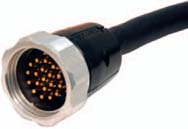
FIGURE 12.9 Socapex SL 61 connect or.( Photograph by C.B.I. Cables.)
[Note: The National Electrical Code, Article 520, permits the SJO covering in this application because the S/O jacket is too big to fit in the Socapex, but all other theatrical applications where portable cable is used must use cable with an S/O jacket.]
COMPANY SWITCH
Unless you are on a small tour where you are also the master electrician, you will not need to know much about a company switch until it's not there. Suppose you are advancing the dates with the road manager or production manager. One of the things on your checklist should be asking about the available power. You need to be able to not only recognize the power box but also decipher what it can provide. Most installed company switches in theatre are on the wall opposite the fly rail. Some are on the back wall (not ideal, as it takes more cable to get to them—note to self: bring more feeder cable). Now for the important part: What power will this panel deliver? In the United States, we speak of 3Ø/5 wire power; translated, that means that on the face of the box a label should show a number (i.e., 100, 200, 400, 600, or 800 amps). That number is multiplied by the number of phases (Ø). Therefore, a 400-amp, 3-phase system will deliver 1200 amps. Figure 12.10 shows a Union Connector company switch. Note the color-coded, panel-mounted Cam-Lok output connectors at the bottom of the panel with protective covers.
The features include no exposed screws or holes and a positive connection made via the exclusive Lektralink principle, which makes a secure connection easy. In vulcanized versions, the connection is also waterproof, a good thing when working outdoor festivals with the possibility of rain showers. As best we can determine, no rental house uses anything other than Cam-Lok connectors on #2/0 and #4/0 single power feeders, so you should be able to travel anywhere in the United States and be able to rent additional feeder cable for situations that require longer runs.
If you do not see any connectors, then the system is using either a buss bar or a bear-end into lug connection.
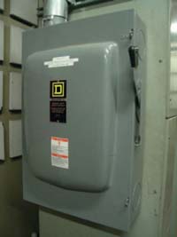
FIGURE 12.10 Company switch.( Photograph by Union Connector.)
for a buss bar connection, you need sister lugs on the end of your cables. For a bear-end connection, you should have no connector on the end of your power cable. It is standard practice in the United States to carry 5 runs of 100 feet of #4/0 feeder cable with Cam-Lok connectors, plus a set of 5- to 10-foot cables with Cam-Lok single connectors on one end and bear ends on the other (with a set of sister lugs in your drawer, just in case). Understanding this doesn't make you a master electrician, but it may help you look not too foolish to the survey team.
TRANSFORMERS
It is somewhat unusual to find U.S. tours carrying transformers, although we once needed them on an aircraft carrier to do a television show, and they are often found on temporary festival sites where the local power company has made a high-voltage (say 480 vac) power source available and that power must be reduced to a useful level, usually 208/120 vac or 240 vac. The need for transformers becomes a more important issue while touring overseas. As was already mentioned in Chapter 8 in our discussion on touring in Japan and South America, the need to match power for moving luminaires can sometimes require that a transformer be placed in service.
A transformer (Figure 12.11) is a device that transfers electrical energy from one circuit to another through inductively coupling. Two conductors are referred to as being inductively coupled when they

FIGURE 12.11 Transformer.( Photograph by Paul Dexter.)
are configured such that a change in current flow through one wire induces a voltage across the ends of the other wire. A changing current in the first circuit (the primary) creates a changing magnetic field. This changing magnetic field induces a changing voltage in the second circuit (the secondary). This effect is called mutual induction. If a load is connected to the secondary circuit, electric charge will flow in the secondary winding of the transformer and transfer energy from the primary circuit to the load connected in the secondary circuit.
Put simply, a transformer can either raise (boost) or reduce (buck) the output voltage when voltage is applied to the device. Therefore, whatever voltage is available onsite can be, in a sense, modified to the needs of the equipment you are trying to power. The transformer also offers the advantage of isolating the power from other sources that may be creating hum or buzz in electronic equipment.
PORTABLE GENERATORS
Many sites, especially festivals, require more power than what is available. Temporary power can be brought in by the local power company, but it may be more cost effective for a one-day show to simply rent portable generators to provide the additional energy necessary. Movie companies have been doing this for years. Figure 12.12 shows Cat generators;
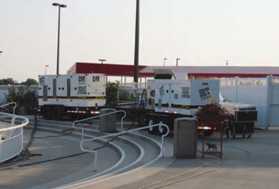
FIGURE 12.12 Portableg enarators, (Photograph by Paul Dexter)
the housing is called a blimp, and it reduces the noise produced by the diesel engine. A generator is essentially a self-contained transformer that can produce either A/C or D/C power (although there are some D/C-only portable generators). In this case, the generator provides its own mechanical energy via a motor to convert that energy into electricity to serve as a power source for other machines. Electrical generators, for our purposes, are normally diesel powered. Depending on the situation, they may be blimped, or made quiet, by adding a covering and exhaust system that reduce the noise factor. This blimping does raise the rental price, so determining if it is needed can impact the costs you will incur.
There is one other issue with generators. The ones used to power electronic equipment must have electronic control, a feedback system that electronically maintains the selected output voltage and frequency. The cycle or frequency for any device must be maintained with a motor or fan, such as via computer control or cooling fans placed in the dimmer racks or luminaires so they receive a steady 60 Hz. Not all generators come with this feature.
CABLE REELS
A weak link in the lighting system is the 100- to 200-foot control cables to the lighting console that are placed out in the house. Normally, a show, the cable is disconnected from the console, and a local stage
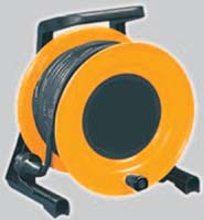
hand starts pulling it to the stage to coil it up and dump it in a road case. Along the way, the connectors gets caught under chairs and dragged through spilled soda. Save your cable by asking for a cable reel (Figure 12.13).
CABLE CROSSOVERS
If your main feeder cables get cut or pulled out, or the Socapex cable that you ran across the backstage
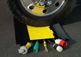
FIGURE 12.14 Cable crossover. (Photograph by Yellow Jacket.)
area or your control console cable that is taped down with gaffer tape across the aisle in the audience gets damaged, you are not likely to be putting on a show. Look into cable crossovers (Figure 12.14). They can save expensive cable and prevent a law suit when someone trips over the cable. Don't expect the hall to have them; carry them as part of your touring package.