
5
PACKET BACKHAUL NETWORK
5.1 INTRODUCTION
A backhaul network is usually responsible for transparently transmitting service from the front of an end user, such as a digital subscriber line access multiplexer (DSLAM) and a base station, to the point of presence (POP), and vice versa. The networking technique used in backhaul network is often called transport technology. In this chapter, we also use the word “transport” for the technology related description.
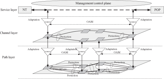
Figure 5.1 shows a typical transport network and its networking requirements:
- Management/Control Plane: A transport network must be a strictly controlled network. Generally, all the network resources are managed by the network management systems (NMS). A transport network is usually dependent on NMS, which provide the centralized control on the whole network. For a transport network, the control plane is optional, which means that the network should work well without any control plane. But in fact, most networks have a control plane because the control plane can facilitate the network management.
- Traffic Engineering: A transport network is generally a traffic engineered network. The forwarding path, service access control, bandwidth allocation, and so on, are all under unified control. In most cases, the technology used in transport network is connection-oriented-based technology. Traffic engineering is an important means to satisfy the service level agreements (SLA).
- Layered Network: A typical transport network is usually divided into three layers that are functionally separated.
- Service Layer: The layer of service traffic. The client service is available in this layer.
- Channel Layer: This layer provides the separation between different service instances for service-level management. The channel layer label often can be viewed as a identification within the network.
- Path Layer: This layer provides the transport connection between the ingress node and the egress node for each service. The transport network nodes forward the traffic based on the path layer label—for example, VC4 timeslot for SDH network.
For the three layers, the upper layer is carried on the lower layer. The adaptation function is used to encapsulate the upper-layer traffic into lower-layer traffic. - Operation, Administration, and Management (OAM): Control-plane-independent OAM is a very important feature of transport network. OAM provides many tools for connectivity monitoring, performance monitoring, fault location, and so on. The connectivity monitoring tools is the basis for fast restoration in case of failure. The performance monitoring tools is critical for testing the satisfaction of the QoS requirement. The fault location can help the operator to quickly locate the failure point. Many alarm functions in the OAM tools can also play very important roles in practical network management. OAM is usually present in each layer of the network.
- Fast Protection: Fast protection is another very important feature of transport network. Fast restoration is a very popular service requirement. Many OAM tools are designed for helping the fast protection implementation. Typically, transport network should recover the service in 50 ms when a single failure occurs. Fast protection is usually present in the path layer, but also in the channel layer in some cases.
Figure 5.1. Transport network architecture.
5.1.1 From SDH/SONET to Packet Transport
SDH/SONET has been proved to be a very successful technology used in transport/backhaul network. It has been widely deployed around the world. It has provided very good support for voice service and virtual private line service.
However, now the voice service is evolving from TDM traffic (i.e., 2G), to IP traffic (i.e., 3G and LTE); meanwhile data service is becoming popular. Most of the network traffic becomes data traffic with respect to the rapid growth of data service in IP form. As a TDM-based technology, SDH/SONET is hard to provide efficient support for this type of service.
- Packet service is a kind of burst service, which means that it is not even during its transmission. SDH/SONET can only provide fixed/hard bandwidth for each service, which means that it cannot efficiently transmit the packet service with statically multiplexing.
- SDH/SONET is designed with 10 Gbps as the highest rate. However, the bandwidth demands are growing so fast thanks to the data service. A rate of 10 Gbps might be hard to satisfy the bandwidth demands in future years.
Packet-based technology can solve the above problems. The statistically multiplexing feature of packet switching is good at transmitting the burst traffic. The bandwidth of packet switching is also easily increased by updating the switch fabric, line card port, and so on. IEEE is working on the 40GE/100GE standard, and until now the most technical problem has been resolved.
5.1.2 From Legacy Packet Technology to Packet Transport Technology
The legacy packet switching technologies are seldom used in a transport network. The Ethernet is always used as local network technology, while IP is used in a router core network. Thus, prior to its deployment in this area, many new functions should be integrated into packet switching to satisfy the requirements of transport network as described previously.
5.1.3 Packet Transport Technologies
The most acceptable way to build up a new packet transport technology is to stand on the basis of the current popular packet switching techniques. At present, there are three most popular packet switching techniques: IP, Ethernet, and MPLS.
IP switching is regarded as the most expensive solution because it uses of the variable-length match for forwarding. The Ethernet and MPLS are thought of as the most suitable techniques for extension to transport network. The following sections respectively describe the enhancement to the two techniques to become packet transport technologies. Since there are not many new things in management plane and layered network, the sections will focus on the other aspects shown in Figure 5.1, especially OAM and protection.
5.2 ETHERNET BACKHAUL NETWORK
5.2.1 Extending Ethernet into Carrier Network
The Ethernet is used as the most popular technology for local area network. It also began to be viewed as a promising access technology. However, since the Ethernet is designed for LAN application, it is hard to be applied in carrier transport network:
- Carrier-class OAM feature was not defined.
- Slow restoration: Ethernet restoration relied on the convergence of the spanning tree protocol, which needs at least hundreds of milliseconds, even several seconds.
- Traffic engineering is unsupported.
- Scalability is not good because the flooding and spanning tree protocol cannot support a big network with thousands of nodes.
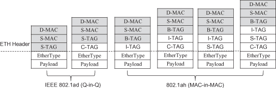
In past years, IEEE and ITU-T put much effort on extending the Ethernet into the carrier network. IEEE 802.1ad defined provider bridges that support the demarcation of customer network and provider network by service VLAN tag. The function enables the flooding traffic to be limited in its owner domain. IEEE 802.1ah, published in 2008, defined provider backbone bridges that support of customer network and provider network by service instance tag and MAC-in-MAC encapsulation. This function separates the MAC address space of both the customer network and the provider network, both of which relieve the burden of MAC address table. These two standards provide much improvement of the scalability of the Ethernet network (Figure 5.2).
Figure 5.2. IEEE 802.1ad and 802.1ah.
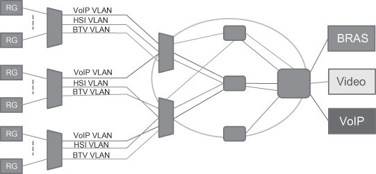
IEEE 802.1Q, 802.1ad, and 802.1ah also provide the support of a network management system that can be used to configure the Ethernet VLAN network. In a practical network, a point-to-point VLAN connection is a kind of typical deployment because in operator networks a point-to-point connection is the most commonly used connection type (Figure 5.3).
IEEE and ITU-T also developed a very strong OAM and protection function for the Ethernet network. This is a key extension for the Ethernet to be used in an operator network.
Figure 5.3. Ethernet in operator network.
5.2.2 Ethernet Operation, Administration, and Management (ETH OAM)
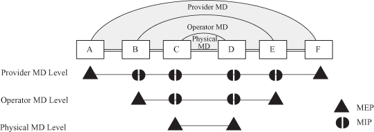
IEEE and ITU-T have defined some concepts for describing the OAM function. The maintenance domain (MD) is an enclosed domain that includes all the nodes connections to be maintained by the management system of the domain (Figure 5.4). Difference management systems have different maintenance scopes. The MD level is used to describe the scope of a maintenance domain. An MD with larger MD level may cover a smaller MD. Generally, the objects to be maintained are the connections contained in the maintenance domain. For a connection under maintenance, the group of its end points is called a maintenance association (MA), and each end point is called an MA end point (MEP). MEPs have many important OAM functions including preventing the leakage of the OAM messages generated from the maintenance domain. An MD intermediate point (MIP) is a point inside the maintenance domain, and it can help to complete some OAM functions, such as link trace and loopback, to be introduced in the following text.
Figure 5.4. Maintenance domain.
IEEE and ITU-T has developed a set of OAM tools to help network management. Two important aspects of Ethernet OAM are fault management and performance monitoring.
5.2.2.1 Fault Management.
Fault management deals with the issues regarding link failure or node failure.
Continuity Check (CC) and Remote Defect Indication (RDI).
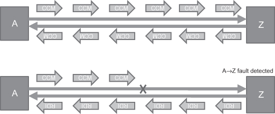
Continuity check is the most used OAM function because it can detect link/node failure in milliseconds. The detection is between the two ends (MEPs), of a connection, typically bidirectional connection. The two ends send continuity check messages (CCM) to the remote peer(s) periodically (Figure 5.5). If one end doesn’t receive any CCM in 3.5 times of the period, it will declare a fault detected on the direction from the remote side to the local side. To let the remote peer(s) know of this failure, it will set the remote defect indication (RDI) flag in the CCM messages sent by itself to the remote side (Figure 5.5).
Figure 5.5. CCM and RDI.
Besides the fault detection, continuity check can also be used for connectivity verification. The CCM messages carry the MD name, the MA name and MEP ID for this purpose. If one end received an unexpected combination of the MD name, the MA name, and the MEP ID, it will declare a mismatch or misconnection defect. All the defects detected by a continuity check will be reported to a network management system to notify the operator.
Loopback.
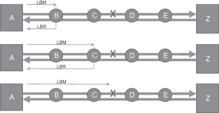
Loopback is the most used OAM tools for locating the failure point. Similar to continuity check, the idea of loopback function is also very easily understood. When a failure is detected on the connection, the NMS operator or the node itself will initiate a loopback function to locate the failure. Figure 5.6 shows an example:
Step 1: Node A learns a failure with respect to CCM loss or the RDI flag in the CCM received from Z, and it initiates loopback function and send a loopback message (LBM) to the first intermediate node, B.
Step 2: Node B receives the LBM and will return a loopback response (LBR) message to A.
Step 3: Node A receives LBR from node B, and it makes sure that the segment from A to B is OK. Node A then sends the second LBM targeted to the second intermediate node, C.
Step 4: Node C receives the LBM and will return a loopback response (LBR) message to A.
Step 5: Node A receives LBR from node B and then sends the third LBM targeted to the third intermediate node, D.
Step 6: Node A doesn’t receive LBR from node D after a fixed time, and declare that the failure is located on node D or on the link between node C and node D.
Figure 5.6. Loopback function.
Loopback can only work with bidirectional connection because LBR messages must be sent back to the loopback initiator. Fortunately, most connections in a transport network are bidirectional in practice.
Link Trace.
Link trace is often used for topology discovery in the Ethernet network. In many cases, the head end of a connection doesn’t know about the MAC addresses of the intermediate nodes. However, to know about this information is very important because it is useful when performing loopback function. Figure 5.7 shows the procedure for a head end collecting the connection topology:
Step 1: Node A initiates a link trace message (LTM) with TTL = 64 on the connection.
Step 2: The first intermediate node, B, receiving the LTM will return a LTR with TTL = 63 to node A and generate a new LTM with TTL = 63 to next nodes.
Step 3: The second intermediate node, C, receiving the LTM with TTL = 63 will return a LTR with TTL = 62 to node A and generate a new LTM with TTL = 62 to next nodes.
Step 4: Node D, E, Z will do the things that are similar to what node B and node C have done. Note: An exception is that node Z will not generate a new LTM because it is the end of the connection.
Step 5: Node A receives all the LTRs and sort the MAC addresses carried in the LTRs based on the TTL value. The less the TTL value, the closer the node to node A itself.
Figure 5.7. Link trace function.
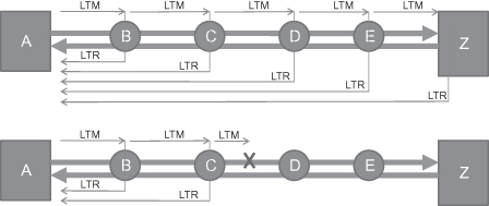
Besides topology discovery, link trace also can be used for fault location. In case of a failure on the connection, the head node will not receive LTR message as the lower part of Figure 5.7 shows from the downstream node of the failure point, and thus it can learn failure location. Similar to loopback function, a link trace also can only work with a bidirectional connection.
Alarm Indication Suppression/Signal.
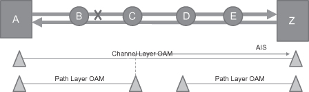
Alarm indication suppression/signal (AIS) is a very useful complementary tool for the network management. It is a common case that when a link/node failure occurs, many OAM instance will detect the failure because there should be many connection passes through the link/node. If all related OAM instance reports a failure to network management system, it is hard to find where the failure occurs on earth because NMS gets too many fault reports. AIS is used to suppress all other fault reports except for the OAM instance, which generates AIS.
Figure 5.8 shows an example of the AIS application. A path layer OAM instance is established between node A and node C and also between node D and node Z. A channel layer OAM instance is established between node A and node Z. When the link between node B and node C fails, node C and node Z will detect the failure. In this case, node C will generate AIS messages that are sent on channel layer OAM instance. When node Z receives the AIS message, it will suppress the fault report to NMS. The result is that only node C reports a fault to NMS, and it is easy for an operator to identify the failure source.
Figure 5.8. AIS function.
5.2.2.2 Performance Management.
Performance management OAM is responsible for monitoring the service/path quality. It can be used to detect the signal degrade, partial fault, and so on. Two typical performance monitoring OAM tools are loss measure and delay measure.
Loss Measurement.
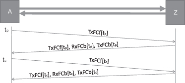
Loss measurement is used to monitoring the packet loss ratio for a connection. Figure 5.9 shows the principle of loss measurement used in ETH OAM.
Step 1: The head-end A sends the current transmitted frame count at time tp, TxFCf[tp], to the far end Z.
Step 2: The far-end Z returns the information of current received frame count, RxFCb[tp], and current transmitted frame count, TxFCb[tp], at time of receiving message from A. The return message also includes the receiving TxFCf[tp].
Step 3: The head-end A sends the current transmitted frame count at time tc, TxFCf[tc], to the far end Z.
Step 4: The far-end Z returns the information of current received frame count, RxFCb[tc], and current transmitted frame count, TxFCb[tc], at time of receiving message from A. The return message also includes the receiving TxFCf[tc].
Figure 5.9. Loss measurement function.
Based on the information of the two rounds and its local received frame count at time tp and tc (i.e., RxFCl[tp] and RxFCl[tc]), the bidirectional packet loss ratios can be calculated out according to the following formulas:
![]()
![]()
The Frame Lossfar-end represents the loss ratio on the far end, and the Frame Lossnear-end represents the loss ratio on the local end.
In Ethernet OAM, there are two ways to carry the frame count information exchanged as specified in Figure 5.9. One is piggybacked on CCM, and the other is to define new messages for them—that is, loss measurement message (LMM) and loss measurement reply message (LMR).
Delay Measurement.
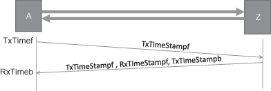
Delay measurement is used to detect the packet transmission delay from one end to another end. Figure 5.10 shows the principle of delay measurement used in ETH OAM.
Step 1: Head-end A sends a delay measure message (DMM) to the far-end Z. The DMM message carries a timestamp, TxTimeStampf, which represent the time sending the message.
Step 2: The far-end Z receiving the message will return a delay measure reply message (DMR) to node A. The DMR message will carry the timestamp for the time receiving the DMM message, RxTimerStampf, and the timestamp for the time transmitting the DMR message, TxTimeStampb. It also returns the receiving TxTimeStampf.
Step 3: Node A receiving the DMR will calculate out the bidirectional transmission delay according to the receiving time RxTimeb and timestamps carried in DMR with the following formula:
![]()
Figure 5.10. Delay measurement function.
5.2.2.3 Additional OAM functions.
This section shows the most frequently used OAM tools. In fact, there are many other OAM functions, such as client signal failure, lock, test, and so on. The reader can find the details in the recommendation ITU-T Y.1731.
5.2.3 Ethernet Protection Switching
End-to-end service recovery in 50 ms in the case of network failure is a typical requirement of transport network. Ethernet protection switching mechanism can switch the traffic from the failed working connection to a healthy backup connection. Ethernet gains the fast recovery capacity with the help of the fast failure detection with OAM function and the fast protection switching trigger mechanism. There are two typical protection switching mechanisms: linear protection switching and ring protection switching.
5.2.3.1 Ethernet Linear Protection.
Ethernet linear protection switching is only applicable for point-to-point VLAN connection at present. In a linear protection switching mechanism, for each transport connection, a backup transport connection is preconfigured for protecting the service on it. The two connections are formed as a protection group. In a protection group, the transport connection used in normal status is called “working entity,” and the another one is called “protection entity.”
There are two typical linear protection switching mechanisms:
1+1 Protection: The traffic is sent both on working entity and protection entity. The far end takes one copy of the traffic from one of them.
1:1 Protection: The traffic is sent only on one of working entity and protection entity.
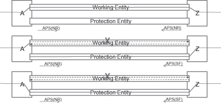
1:1 protection switching is most common in practice because the protection entity can be used for carrying other service traffic that is not as important. Ethernet linear protection switching utilizes an automatic protection switching (APS) message to coordinate the protection switching action on the both ends. Figure 5.11 shows the APS application in the 1:1 protection switching case.
Step 1: In normal status, the traffic is transmitted and received on working entity. The APS messages transmitted on the protection entity carry “No request (NR)” information, which means no protection switching request at present.
Step 2: A unidirectional failure occurs on the working entity in the direction from A to Z. Node Z detects the failure and switch to transmit and receive traffic from a protection entity. It also sends the APS(SF) message to the far end, A. SF means signal failure.
Step 3: When node A receives the APS(SF) message, it will also switch to transmit and receive traffic from protection entity.
Figure 5.11. Ethernet 1:1 linear protection switching (failure case).
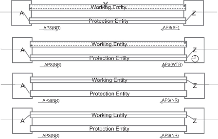
After the three steps, the service traffic will be transmitted on and received from the protection entity on both directions. After the failure is repaired, there are two optional operations: return to work entity (revertive mode) or remain on protection entity (nonrevertive mode). In practice, the revertive mode is the most frequently used. Figure 5.12 shows the protection switching in the case of link recovery with revertive mode:
Step 1: In failure status, the traffic is transmitted and received on a protection entity. The APS messages transmitted on a protection entity carry a “signal failure (SF)” indication.
Step 2: The failed link gets repaired. Node Z detects the recovery by the OAM function. It will start a wait to restore (WTR) timer. During the WTR timer running, node Z also sends an APS(WTR) message to notify node A current status. Note that the WTR timer is very useful in carrier network. It can prevent the protection switching flapping, which is caused by the instability when repairing a failure. The WTR timer is usually between 5 and 12 minutes.
Step 3: When the WTR timer expires, node Z will switch back to a working entity. It will also transmit an APS(NR) message to node A.
Step 4: When node A receives an APS(NR) message from node Z, it will also switch back to a working entity. To this step, the client traffic has been switched back to a working entity in both directions.
Figure 5.12. Ethernet 1:1 linear protection switching (recovery case).
Ethernet linear protection switching also provides many other APS events to cover the cases that would happen in practice as much as possible. For example, manual switch and force switch are defined for operator’s maintenance activity. In fact, the whole protection switching logic is a very complicated system, although its principle is very easily understood. People who have great interest can find the details in ITU-T G.8031.
5.2.3.2 Ethernet Ring Protection.
Ethernet ring protection (ERP) defined by G.8032 has been developed on the principle of utilizing generic mechanisms inherited from the traditional Ethernet MAC and bridge functions. The requirement of ERP comes from the fact that many of the present networks have ring-link topologies. Another reason is that linear protection switching can only protect point-to-point connection, while ring protection can achieve the protection of multipoint-to-mulitpoint connection. For ERP, the objective of fast protection switching is achieved by integrating mature Ethernet operations, administration, and maintenance (OAM) functions and a simple automatic protection switching (APS) protocol for Ethernet ring networks.
Ring Topology.
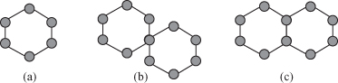
Figure 5.13 shows the possible variants of Ethernet ring topology. The current G.8032 supports single rings in Figure 5.13a and 5.13b. In the multi-ring cases of Figure 5.13c, rings can be interconnected via a shared link. In the second version of G.8032,1 multi-rings and ladder networks consisting of conjoined Ethernet rings are also supported by the Ethernet ring protection.
Figure 5.13. Possible ring topologies: (a) Single ring. (b) Two single rings with a shared mode. (c) Multi-ring with shared link and nodes.
Client Channel, APS Channel and Channel Loop Avoidance.
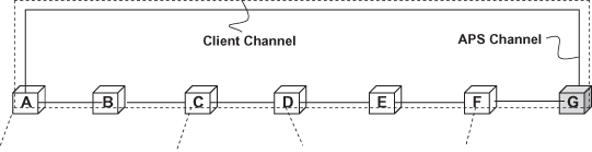
ERP separates a ring APS channel from client channel since one APS channel can be used to carry APS information for many client channels. ERP uses a separate VLAN within the scope of the ring as a ring APS channel (R-APS channel).
As Figure 5.14 shows, both the client channel and the R-APS channel will form a ring loop in the ring topology. The ring loop will destroy the network in the Ethernet because the Ethernet has no information as basis of terminating an unknown frame in a data forwarding plane. To break the loop, the ERP mechanism will ensure that there is at least one blocked ring port onthe ring.
Figure 5.14. Client channel and ring APS channel.
In the normal state, one ring link is designated as the ring protection link (RPL), which blocks Ethernet traffic to guarantee the loop avoidance. An RPL owner, which is attached to one end of the RPL, is designated to perform traffic blocking. The RPL owner sets the port on the RPL as blocked, and thus it drops any client traffic received from or sent to the RPL. The RPL owner plays a very important role in G.8032, because it is responsible for use of the RPL for ring protection switching. When a failure occurs, the RPL owner will open the RPL port to resume the connectivity of all ring nodes.
Ethernet Ring Protection Switching.
Figure 5.15 illustrates a scenario in the case of link failures which shows ERP processes as follows:
Step 1: In the normal state, the RPL owner blocks its port connected to the RPL. The RPL owner is also responsible for transmitting APS(NR, RB) messages on the ring to indicate that the ring is OK and the RPL is blocked.
Step 2: A link failure occurs between node C and node D.
Step 3: Nodes C and D detect the local SF condition, and each node flushes its FDB, blocks the failed port, and transmits an R-APS(SF) message on both ring ports, followed by periodic transmission of the same messages, while the SF condition persists.
Step 4: Other nodes flush FDBs on when receiving the R-APS(SF) message from node C or node D. In addition, the RPL owner will unblock its port on the RPL.
Step 5: The following R-APS(SF) will not trigger FDB flush and the ring will enter the protection state.
Figure 5.15. Example sequence diagram of link failure.
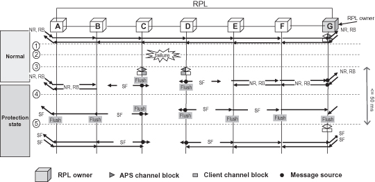
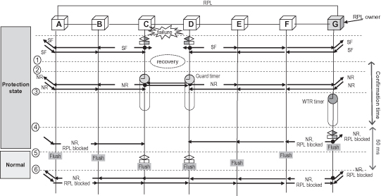
Figure 5.16 illustrates a scenario in the case of link failures which shows ERP processes as follows:
Step 1: The link between node C and node D is repaired.
Step 2: Nodes C and D detect the local SF, which is cleared. The two nodes will start the guard timer, and transmit an R-APS(NR) message on both ring ports. Note that the node running guard timer will discard R-APS messages. Here the guard timer is used to prevent the full loop because the remaining R-APS(SF) messages would unblock the ports on node C and D before the RPL owner blocks the RPL port. The guard timer will expire in a relatively short time, which could be several seconds.
Step 3: The RPL starts the WTR timer while receiving an R-APS(NR) message to make sure the link repair has completed. The WTR timer is usually between 5 and 12 minutes.
Step 4: After the WTR timer expires, the RPL owner will flush the FDB, block the RPL link, and send an R-APS(NR, RB) message to notify the whole ring.
Step 5: All other ring nodes will flush the FDB when receiving an R-APS(NR, RB) message. In addition, node C and D will unblock the blocked ports and stop transmitting the R-APS(NR) message. To this step, the ring has switch back to the normal state.
Figure 5.16. Example sequence diagram of link recovery.
Here, this section only provides a general description of the procedure in case of the simplest scenario. The ITU-T has defined much more, such as manual switch, nonrevertive, force switch, ring interconnection, and so on. The readers who have an interest can find the details from ITU-T G.8032.
5.2.4 Provider Backbone Bridge—Traffic Engineering (PBB-TE).
The PBB-TE is an extension of provider backbone bridge technology which is specified by IEEE 802.1ah, and it defines a kind of connection-oriented network based on the Ethernet frame format. The PBB-TE inherited the forwarding rules from the Ethernet legacy—that is, forwarding based on destination address (DA) and VLAN TAG. In a network, usually only a subset of Ethernet VLAN is used as PBB-TE. The PBB-TE VLAN has the following features:
- It forbids self-learning and flooding unknown frames.
- It does not attend the process of spanning tree protocol.
- The forwarding table is statically configured by a network management system (NMS).
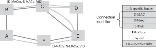
A PBB-TE uses the triple <DA, SA, VID> as a connection identifier. For point-to-point PBB-TE connection, DA is the unicast address of the connection end. For point-to-multipoint PBB-TE connection, DA is the multicast address. The triple must be specified in the packet header as the forwarding information as shown in Figure 5.17.
Figure 5.17. PBB-TE connection.
Extension of ETH OAM for a PBB-TE Network.
It is almost the same for the end-to-end OAM function (such as continuity check) between the Ethernet legacy and the PBB-TE. The only difference is that the header of the OAM packet should be replaced by the PBB-TE connection identifier. But for the OAM function involving intermediate nodes, since the destination address field has been occupied by a PBB-TE connection identifier, it cannot be used for targeting the intermediate nodes. In PBB-TE OAM, for loopback function, the target intermediated node information is carried in the LBM PDU. In addition, since the PBB-TE connection allows the different VLAN IDs to be used in two directions, for loopback and link trace function, the reverse VLAN ID information is also needed to be carried in LBM and LTM. The reverse VLAN ID information is used to indicate the correct reverse connection identifier, which is encapsulated on LBR and LTR.
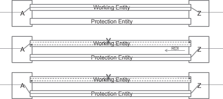
PBB-TE Linear Protection.
PBB-TE also specified its own protection switching mechanism. It is a kind of 1:1 linear protection switching, but it does not utilize the APS mechanism used in the VLAN network. The difference is that it uses RDI to trigger protection switching in case of unidirectional failure as shown in Figure 5.18. In addition, PBB-TE makes a large simplification according to Ethernet linear protection switching by assuming that PBB-TE connection is always under the same management system. The reduction includes the negotiation of manual switch, force switch, and so on.
Figure 5.18. PBB-TE protection switching.
At present, the IEEE has completed the standardization of PBB-TE. People can find the details from IEEE 802.1Qay.
5.3 MPLS BACKHAUL NETWORK
5.3.1 Extending MPLS into Backhaul Network
At present, MPLS is usually used as a core network technology. Most core routers have MPLS capacity. MPLS has a short, fixed label for efficient forwarding. In addition, the greatest advantage of MPLS technology is that it can support the most used service types, such as L2VPN, L3VPN, TDM service, and so on. However, since MPLS is designed for core network, it has the following shortcomings when it is applied in a carrier transport network:
- MPLS OAM is dependent on a control plane and an IP layer, both of which are not necessary in a transport network.
- MPLS fast reroute is hard to use when there is a large number of LSPs.
- MPLS LSP is defined as unidirectional LSP, while in a transport network the most case is bidirectional connection.
- Some MPLS forwarding behavior is dependent on an IP layer.
- MPLS cannot work without a control plane.
As a promising technology, many vendors and carriers did much work on how to make it a transport technology.
5.3.2 MPLS-TP: A Transport Profile of MPLS Technology
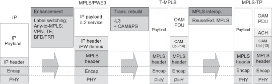
IETF has started to define a transport profile of MPLS technology for the application in a transport network. Figure 5.19 shows the evolution from MPLS to MPLS-TP. Actually as the figures shows, ITU-T had specified a technology transport MPLS (T-MPLS), which removed the layer 3 dependence and added the function of data-plane-based OAM and protection switching. However, T-MPLS definition cannot interoperate well with current MPLS network become it changes some definition of MPLS packet format. IETF refused the T-MPLS work and started the MPLS-TP work. The MPLS-TP will produce the following enhancement with regard to MPLS:
- It will have centralized NMS, and it must be independent of the control plane.
- It must support OAM and protection switching in the data plane.
- Forwarding must be based on an MPLS label. PHP and ECMP are disabled.
- OAM must be carried in an ACH channel.
Figure 5.19 presents a general summary of the evolution from MPLS to MPLS-TP.
Figure 5.19. From MPLS to MPLS-TP.
5.3.3 MPLS-TP Standardization Progress
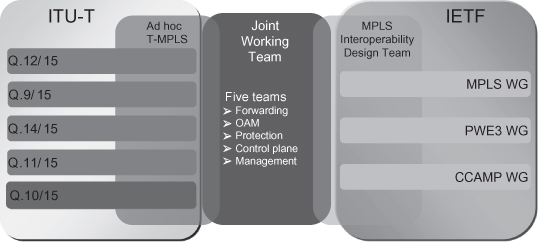
The MPLS-TP standardization work was started from the first half of 2008. The standardization work is under the MPLS-TP Joint Working Team, which is formed by the IETF and the ITU-T as shown in Figure 5.20. Most of the transport network vendors are its members. It is one of the most active working groups in IETF.
Figure 5.20. MPLS-TP standard body.
According to the opinions of most members, the MPLS-TP should have a function similar to that of present transport technology—that is, strong OAM and protection, strong central management, and so on. However, most of the mechanisms haven’t been specified at present.
5.3.4 A Comparison Between MPLS-TP and Ethernet Transport
It is like a drama for the battle between MPLS-based and Ethernet-based transport technologies. The battle can be traced to 2005 or even before. Ethernet transport technologies, especially the PBB-TE, had a very good position at the beginning. More than 10 vendors had declared to support the PBB-TE at that time. It also started to be deployed in some parts of the carrier network from 2005 to 2007. However, entering 2008, several carriers made a declaration to abandon the PBB-TE one by one. The MPLS-TP gets much support from carriers, and thus the MPLS-TP seems to be nearly winning the battle at present. The background is that the router camp is much stronger in the market decision because data communication is dominated by routers in carrier networks.
With respect to the technical view, the MPLS-TP has the following advantages compared with Ethernet technologies:
- It can be seamlessly integrated into routers as per present-day design specifications.
- It inherits the pseudowire feature from MPLS and thus has more mature support of different services, such as E1, STM, fiber channel, ATM, and so on.
- It can perfectly support L3VPN, which also inherits from MPLS technology.
In fact, Ethernet-based transport technology also has its own advantages, such as the perfect merge of connection-oriented and connectionless technique, and thus have good support on multipoint-to-multipoint connection. Their standardization also goes further than MPLS-TP. However, the market will decide everything. This is not to say that Ethernet transport has been replaced. The battle is still going on. The Ethernet is still getting the market share because the market is different everywhere. For example, Ethernet ring protection is getting more and more attention from carriers.
5.4 SUMMARY
This chapter provides a general overview of current packet transport technology progress at present. Packet transport technology is very promising in the application of a backhaul network from the market point of view. There are two routes that are used to introduce the packet transport technology into the real world: from Ethernet or from MPLS. This chapter gives a general description of progress of the two routes. Both the technologies have good support for transport network application, and they will find their own positions in the world market.
Note
1 G.8032 v2 have developed some mechanisms to support multi-ring topology.
BIBLIOGRAPHY
1. IEEE Std. 802.1Q, Virtual Bridged Local Area Networks, 2005.
2. IEEE Std. 802.1ad, Virtual Bridged Local Area Networks—Amendment 4: Provider Bridges, 2005.
3. IEEE Std. 802.1ah, Virtual Bridged Local Area Networks—Amendment 6: Provider Backbone Bridges, 2008.
4. IEEE Std. 802.1Qay, Virtual Bridged Local Area Networks—Amendment: Provider Backbone Bridge Traffic Engineering, 2009.
5. ITU-T Recommendation Y.1731, OAM Functions and Mechanisms for Ethernet Based Networks, 2008.
6. IEEE Std. 802.1ag, Virtual Bridged Local Area Networks—Amendment 5: Connectivity Fault Management, 2007.
7. ITU-T Recommendation G.8032/Y.1344, Ethernet Ring Protection Switching, 2008.
8. ITU-T Draft Recommendation G.8032/Y.1344 version 2, Ethernet Ring Protection Switching, 2009.
9. ITU-T Rec. G.8031/Y.1342, Ethernet Protection Switching, 2006.
10. J.-D. Ryoo et al., Ethernet ring protection for carrier ethernet networks, IEEE Commun. Mag., September 2008.
11. D. Ward and M. Betts, eds., MPLS-TP Joint Working Team, MPLS architectural considerations for a transport profile, April 18, 2008.
12. ITU-T Recommendation G.8011.1, Architecture of Transport MPLS (T-MPLS) Layer Network, 2006.
13. ITU-T Recommendation G.8011.1 Amendment 1, Architecture of Transport MPLS (T-MPLS) Layer Network Amendment 1, 2007.