
15
ULTRA-WIDEBAND PERSONAL AREA NETWORKS: MIMO EXTENSIONS
The focus of this chapter is on short-range, wireless communication using so-called ultra-wideband (UWB) technology.* The purpose of the chapter is to illustrate the advantages that can be gained from using multiple transmit and (possibly) receive antennas in such systems when appropriate precoding, or beamforming, techniques are employed at the transmitter. Several precoder designs are considered, all of which are based on the optimization of some objective, such as minimizing biterror rate or maximizing the received signal-to-noise ratio or the mutual information between the transmitted and received signals. Importantly, these precoder designs adhere to the strict system and regulatory constraints that relate to UWB transmissions. In fact, these constraints cause the UWB precoder designs to be significantly different from precoders that are used in many narrowband scenarios. Despite the aforementioned restrictions, it will be shown that multi-antenna precoding is a promising practical method of achieving robust, high-rate communication in ultra-wideband networks.
15.1 INTRODUCTION
State-of-the-art ultra-wideband systems transmit data using bandwidths of hundreds of megahertz in frequency bands that are shared with many existing licensed narrowband devices. Transmission of UWB signals over licensed frequency bands will cause interference to the existing licensed narrowband systems. To help mitigate this problem, various regulatory agencies have placed a low transmit power limit on UWB transmissions. For example, the Federal Communications Commission (FCC) in the United States has set an extremely low transmit power spectral density limit of −41.3 dBm/MHz [1, 2]. Despite these severe power restrictions, it has been shown through both theory and practical demonstrations that UWB systems are capable of communicating over short distances at data rates of hundreds or even thousands of megabits per second.
Although these systems have been shown to perform well, it is likely that, with the advent of high-definition video streaming in the home, UWB devices will be required to transmit more robustly—that is, less susceptible to channel fading in frequency—at these high data rates in the near future. One approach to achieving this goal is to employ multiple antennas at the transmitter and (optionally) the receiver, with an aim to exploit the spatial diversity in the channel. Such an approach has been shown to give good results in wireless local area networks (WLANs), such as those based on the IEEE 802.11n specification, and has recently been proposed for use in next-generation UWB systems based on the WiMedia specification [3]. In the case of the IEEE 802.11n standard, provisions have been made to allow systems to obtain channel state information at the transmitter (CSIT) [4]. This information can be exploited to direct the energy of the transmitted signal along the best spatial paths such that information is conveyed robustly and at the highest possible rate. Unfortunately, these beamforming, or precoding1, solutions are not all directly transferable to UWB networks for one reason in particular: The equivalent isotropic radiated power (EIRP) of UWB transmissions must not exceed −41.3 dBm for each megahertz of bandwidth employed (in the United States). Consequently, conventional optimal beamforming techniques based on transmission over the principal eigenmodes of the channel cannot be employed without a power back-off since they create spatial directivity, thus leading to a violation of the aforementioned EIRP restrictions. Moreover, using conventional techniques with a power back-off leads to poor performance [5].
This result triggers several immediate questions, such as What type of precoding scheme achieves capacity in multi-antenna systems with stringent EIRP restrictions? Moreover, can such a scheme be implemented efficiently in practice? Do suboptimal approaches exist, which facilitate implementation while achieving near-optimal performance? Answers to these questions are provided in this chapter.
In the next section, an overview of the concept of UWB is given, which is followed by a brief description of its different guises (i.e., impulse radio and carrier-based). The focus of the chapter, however, is on multicarrier, multi-antenna UWB systems and the optimal precoding schemes that can be employed with such technology; such systems can be thought of as extensions to the single-antenna systems specified by ECMA for UWB communication [6]. Three approaches to designing precoding schemes are described. The first approach is to design the precoder to maximize the mutual information of the transmitted and received messages. It will be shown that the practicality of using precoders that satisfy this criteria is highly dependent upon the operating received signal-to-noise ratio (SNR) and the number of antennas that are used at the transmitter. The second approach to precoder design that is discussed in this chapter is a simple antenna selection scheme whereby information is conveyed from only one antenna on any given frequency bin, noting that the selected antennas for two different frequency bins may not be the same. This precoding strategy actually arises as a solution to the problem of mutual information maximization in some practical scenarios. Finally, the third approach is to design the precoder to maximize the received SNR. This approach has several practical benefits compared to the first approach mentioned above.
Note that throughout this chapter, it is assumed that the amount of channel state information (CSI) that is required to implement a given precoding scheme is available at the transmitter; the practicalities of CSI feedback are not considered, although this can be achieved through a dedicated feedback channel or, when time division duplex (TDD) communication is employed, through channel reciprocity.
15.2 ULTRA-WIDEBAND COMMUNICATIONS
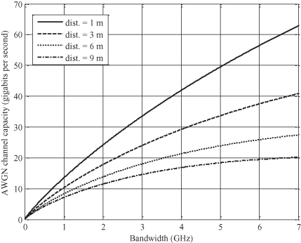
UWB technology is defined primarily according to the bandwidth that is utilized. In particular, the FCC in the United States specifies that a UWB signal must occupy at least 500 MHz or a fractional bandwidth of more than 20% [1, 2]. The typical maximum operating bandwidth of UWB systems is over 7 GHz. This amount of available spectral resource can theoretically facilitate enormous information transfer rates in power-constrained systems. Figure 15.1 provides a simple illustration of these gains by depicting the Shannon capacity2 of an AWGN channel as a function of bandwidth for a fixed total transmit power [i.e., variable power spectral density (PSD)] and various transmitter/receiver separations. Although this illustration is not, perhaps, a practical representation of the capacity of a UWB channel, it gives a clear and simple view of the benefits of utilizing a large amount of bandwidth over short distances in power-limited systems.
Figure 15.1. AWGN capacity versus bandwidth for various transmitter/receiver separations. A line-of-sight, free space transmission model has been adopted, and the total transmit power is fixed at 1 mW, which is divided equally across the band.
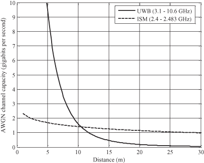
It is also interesting to compare the theoretical limits of communication over a UWB channel to that which can be achieved over other channels. In Figure 15.2, the Shannon capacity of an AWGN channel is plotted as a function of the distance between the transmitter and the receiver for two bands: the UWB band ranging from 3.1 to 10.6 GHz and the ISM band ranging from 2.4 to 2.483 GHz. The standard Friis transmission model was used to generate this graph, where a distance-related path loss exponent of 3.3 was applied. This is a pessimistic assumption for the path loss exponent at short range; nevertheless, the advantage of UWB transmission at close range is clear from this illustration.
Figure 15.2. AWGN capacity versus distance for UWB and ISM bands.
With regard to modulating data, clearly, many different approaches that meet the FCC’s criteria can be employed. Most practitioners divide the admissible approaches into two categories: impulse radio (IR) and multiband systems. Both systems have advantages, disadvantages, and target applications. A brief outline of these two categories is provided below, where the focus is mainly on multicarrier techniques. Following this outline, a short discussion on the coexistence of UWB systems and other networks is given.
15.2.1 Impulse Radio
IR for UWB communication is based on the transmission of very short, discontinuous-pulse waveforms (e.g., Gaussian or Hermitian pulses) that occupy the required bandwidth stated above. The duty cycle of pulse transmission in IR-UWB systems can be very low. One advantage of a low duty cycle is that the problem of intersymbol interference (ISI) is significantly reduced or even eliminated [7]. Many different modulation schemes can be used with IR systems, including both orthogonal and antipodal signaling. However, in order to ensure a low level of interference on other systems operating in the same band, IR schemes require some sort of randomization of the pulse train prior to transmission [7]. The primary application of IR-UWB is for robust communication and accurate positioning. In fact, the IEEE 802.15.4a standard has adopted IR-UWB for these reasons [8].
15.2.2 Multiband UWB
The main alternative to IR-UWB is multiband UWB. In such systems, the total available bandwidth is divided into smaller bands, each of which satisfies the regulatory definition of a UWB signal. Several signaling schemes have been proposed for multiband operation, including direct sequence code-division multiple access (DS-CDMA), multicarrier CDMA, and multiband orthogonal frequency-division multiplexing (MB-OFDM) [7]. The latter of these techniques is the focus of this section. In essence, MB-OFDM is akin to the classic frequency-hop version of spread spectrum, but where hopping is performed on a macroscopic level. In the next section, a brief review of OFDM is given. Following this review, a description of the MB-OFDM approach adopted by much of the UWB industry3 is given.
15.2.3 OFDM
In its simplest form, OFDM is a so-called multicarrier transmission technique whereby data symbols—that is, constellation symbols such as BPSK or QPSK—are transmitted over separate, narrowband subchannels. These subchannels, known as subcarriers, are chosen to be orthogonal, which ensures that—assuming that the receiver is appropriately synchronized and all carrier frequency/phase offsets are accounted for—data symbols transmitted on different subcarriers do not interfere with each other.
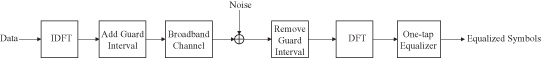
The concept of OFDM was developed in the late 1960s [9]. In modern communications, OFDM systems are realized in the following manner. First, data symbols are arranged into blocks, each of which is processed with an inverse discrete Fourier transform (IDFT) prior to the addition of a guard interval and subsequent transmission. The guard interval—which can take several forms, such as padded zeros or inserted redundant symbols—has two primary purposes: (1) It separates adjacent transmitted blocks in such a way as to prevent interblock interference, and (2) it establishes an orthogonality condition among subcarriers, which allows the signal received on a given subcarrier to be detected independently of other subcarriers. At the receiver of an OFDM system, the guard interval for each block is removed or otherwise processed, and a DFT is applied to each resulting block. These steps effectively convert the broadband channel to multiple narrowband subchannels. Therefore, each original data symbol is simply transmitted through its corresponding subchannel and is, ideally, not affected by intersymbol interference. The received message can be equalized by filtering each received symbol by the reciprocal of the appropriate channel transfer function, which, if the system is designed correctly, can be implemented by a single scalar multiplication for each subcarrier. A baseband block diagram of an OFDM system is illustrated in Figure 15.3.
Figure 15.3. Baseband block diagram of an OFDM system.
15.2.4 Multiband OFDM
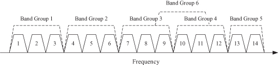
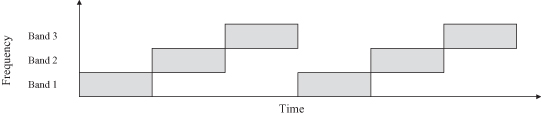
The MB-OFDM technique specified by ECMA 368 is similar to standard OFDM, but with the added feature of allowing different OFDM symbols to be transmitted on different frequency bands. ECMA 368 specifies an MB-OFDM technique whereby the total available bandwidth (3.1–10.6 GHz) is partitioned into six band groups, each of which is further divided into a number of smaller bands [6]. There are a total of 14 such bands, each with a bandwidth of 528 MHz. In particular, as described by Figure 15.4, the first four band groups contain the first 12 bands, the fifth band group contains bands 13 and 14, and the sixth band group contains bands 9–11.
Figure 15.4. Diagram of band group allocation for ECMA 368 multiband OFDM standard.
In the specified OFDM transmission, the information bits are encoded with an error-correcting code, which are then spread using a time-frequency code (TFC). This spreading operation enhances the diversity of the transmission, thus making it more robust to fading and interference, both from other UWB networks and from third-party technology (e.g., WLANs). The current ECMA standard specifies three types of TFCs: three-band time-frequency interleaving (TFI), two-band TFI, and fixed-frequency interleaving (FFI), representing cases where the coded data are interleaved over three bands and two bands and simply transmitted over a single band, respectively. The application of a particular TFC in a given band groups determines the bands that are used for transmission. For example, TFC 1 for band group 1 indicates that OFDM symbols hop over the first three bands, with each hop to a new band occurring with each new OFDM symbol, following a hopping pattern illustrated in Figure 15.5.
Figure 15.5. Illustration of band hopping in an MB-OFDM system based on the ECMA 368 specification using TFC 1 and band group 1.
All other aspects of the MB-OFDM system specified by ECMA 368 are similar to those found in typical OFDM-based WLAN systems, including modulation/coding schemes, packet construction, and pilot subcarrier utilization. The reader is referred to references 6 and 10 for more information on the subject of OFDM and MB-OFDM UWB.
15.2.5 Interference Detection and Avoidance in UWB
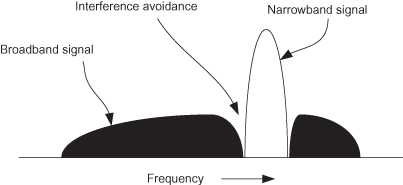
As previously mentioned, many UWB systems occupy a large portion of the 3.1- to 10.6-GHz band. Clearly, this bandwidth can also be used by other licensed narrowband systems. Consequently, problems with the coexistence of UWB systems and licensed third-party systems may arise in practice. In the worst case, a UWB transmission may significantly interfere with a third-party transmission. In order to minimize the impact of this interference, in addition to regulating the UWB transmission power spectrum density (PSD) to an extremely low level of −41.3 dBm/MHz, it has also been proposed that all UWB devices should come equipped with an interference detection and avoidance (DAA) subsystem. By first detecting the signal transmitted by a licensed user and then transmitting at a very low power (or not at all) in that particular frequency band, UWB devices implementing DAA would effectively transmit in an “opportunistic” manner—that is, only when the licensed bandwidth is free for use. Figure 15.6 illustrates the concept of narrowband interference avoidance. In most UWB systems, detection of a third-party transmission can be performed by measuring power levels in certain parts of the band. However, IR and MB-OFDM UWB systems typically implement avoidance techniques in a manner that best suits their respective transmission schemes.
Figure 15.6. Illustration of narrowband interference avoidance.
In IR-UWB systems, interference avoidance can be achieved by modifying the underlying pulse shape according to a desired spectral profile. In reference 11, the application of a notch filter was considered for suppressing narrowband interference arising from third-party transmissions. This approach can also be used for interference avoidance by applying the same notch filter at the transmitter of the UWB device. A related technique for spectral shaping was proposed in [12], whereby a sequence of Gaussian monocycle pulses are weighted, delayed, and summed to create a composite pulse, which can be modulated using any number of IR-UWB techniques. The weights and delays are designed to fulfil requirements on the spectral shape.
In OFDM-based UWB systems, one method of performing interference avoidance is to null one or more OFDM subcarriers to reduce the transmission power within the interference band. In general, however, this method is not capable of providing a sufficiently deep notch due to residual signal power that remains in the so-called interference band, which originates from data transmitted on subcarriers that are adjacent to the band. Advanced signal processing methods have been developed to reduce this residual signal power beyond that which simplistic subcarrier nulling can achieve. In one such method, known as active interference cancellation (AIC), one or more subcarriers located on either side of the interference band are loaded according to an optimization procedure that ensures the residual signal power that remains in the interference band after subcarrier nulling is minimized [13]. Although AIC has been shown to generate notches of 30 dB or more in depth, this approach can also lead to a power amplification at the edges of the interference band [13], which in turn violates the UWB EIRP limit unless a power back-off is applied. A number of approaches have been proposed to mitigate this problem. These include a regularized AIC algorithm that takes the unwanted power amplification into account when designing the signals to be transmitted on the subcarriers adjacent to the interference band [13] and, for multi-antenna systems, a joint optimization procedure that minimizes the signal power in the interference band subject to a constraint on the power transmitted on subcarriers adjacent to this band for all transmit antennas [14].
15.3 MULTIPLE ANTENNAS AND PRECODING FOR UWB SYSTEMS
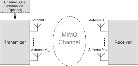
The focus so far has been on OFDM-based UWB communications with single transmit and receive antennas. This section seeks extensions to the use of multiple transmit and/or receive antennas. The corresponding channels between the transmitter and receiver are popularly known as MIMO (multiple-input multiple-output) channels. Please see Figure 15.7 for an illustration.
Figure 15.7. MIMO communications. Transmissions can be with or without knowledge of the intermediate channels. Channel knowledge enables better conditioning of the transmit signals.
15.3.1 Use of Multiple Transmit-Receive Antennas
During the 1990s, theoretical works of Foschini and Gans [15] and Telatar [16] established that the use of multiple transmit and receive antennas can greatly enhance the channel capacities in frequency flat fading channels. One of their key results is that the high SNR capacities of such MIMO channels are a factor min(Mtx, Mrx) times that of single antenna channels, where Mtx is the number of transmit antennas and Mrx is the number of receive antennas. In practice, the increased dimensions due to the multiple antennas are used to either increase the throughput (i.e., data rate) or reduce error rates at reception. Such attempts at utilizing the spatial dimension, in addition to the time domain, are also known as space-time coding. An interesting aspect is that even without the transmitter knowing the forward channels to the receiver; space–time coding enables significant performance improvements compared to single antenna systems. Also note that the MIMO channel induces a mixing of the signals transmitted from different antennas, complicating the symbol detection at the receiver, in general. However, space-time coding with proper design can lead to simple receiver architectures that are optimal for the detection of the transmitted signals. Alamouti’s space–time block code [17] is such an example of a space–time code with an associated simple detection process.
These results naturally extend to frequency-selective channels where OFDM systems dominate. Since the OFDM communication system breaks the frequency selective channel into a set of non interfering flat fading channels, it is possible to consider such systems with N subcarriers and multiple transmit–receive antennas as a set of N MIMO channels that do not interfere with each other [18].
15.3.2 Precoding at the Transmitter
When the transmitters also have access to channel state information (i.e., some knowledge about the channels to the receiver); as might be expected, it is possible to transmit signals that are more suited to these channels and achieve performance better than that given by simple space–time coding. Such precoded transmissions have been widely investigated in the literature. Conventionally, transmit precoding is investigated along with a total transmit power constraint. This is rightly so, because in many systems such as WLANs and cellular systems, total transmit power is the practical constraint. Optimal precoding strategies for total power restricted systems have been derived, for example, in reference 16. Optimality obviously depends on the criterion that needs to be improved. When achieving capacity is the criterion, it is shown that optimal precoding for flat fading MIMO channels reduces to transmitting on the right singular vectors of the matrix composed of fading coefficients of channels between each transmit and receive antennas. Such transmissions, when coupled with receiver processing that utilizes the left singular vectors of the above-mentioned matrix, essentially transforms the MIMO channel into a set of parallel noninterfering channels. These channels are also called eigenmodes, since the received powers of these parallel channels are related to the eigenvalues of the MIMO channel matrix. The total transmit power needs to be properly allocated among these eigenmodes to realize the capacity of the MIMO channels. Thus for total transmit power restricted systems, capacity achieving transmit–receive processing are known in simple and closed form. As will be discussed in the next section, the transmit constraints are different when UWB transmissions are concerned and capacity-achieving transmission schemes are known only for some special cases. Finally, note that as the MIMO channel is decomposed into a set of noninterfering channels by signal transmission on the eigenmodes, the associated symbol detection at the receiver also takes a simple form.
15.3.3 Capacity Optimal Transmitter Precoding for UWB
UWB devices in conception are defined by their ability to coexist with other licensed communication systems, although certain regulatory domains further impose the requirement of completely avoiding the spectral bands where a licensed device is active, as mentioned previously. As a consequence, UWB devices are subject to stringent peak restrictions on their emitted spatial radiation (e.g., FCC part 15.503 [1]). In other words, these systems are equivalent isotropic radiated power constrained. This is to ensure that an unfortunate relative spatial location of a licensed device would not result in a noticeable interference from some UWB device. In fact, the transmit EIRP of UWB devices are restricted on each megahertz of their transmission, which is also necessary due to the wide bandwidths considered.
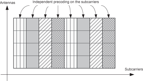
Due to such EIRP restrictions applicable throughout the bandwidth, OFDM-based UWB systems conforming to the ECMA368 specification [6] that specifies subcarrier bandwidths of 4.125 MHz are subject to EIRP restrictions over each of the subcarriers. Thus for a transmitter equipped with CSI, precoding is ideally applied on each of the subcarriers of the OFDM system, independently, as illustrated pictorially in Figure 15.8. From here onwards, most of our focus is on the signal processing applied on some generic subcarrier.
Figure 15.8. Pictorial Illustration of a MIMO OFDM system with eight subcarriers and four transmit antennas. EIRP restrictions on each subcarrier promotes transmit precoding on a per-subcarrier basis.
The problem considered is transmit precoding such that the regulatory EIRP restrictions are not violated. Let us see how the EIRP can be accounted for in the design of transmit precoding methods. For single transmit antenna systems, EIRP restrictions can be accounted for by scaling the transmit power by the peak gain of the antenna radiation pattern. When a transmit antenna array is employed, it produces a further beamforming effect, which needs to be accounted for. When the component transmit antennas are identical, this beamforming effect separates from the individual element patterns and is quantified by the so-called “array gain” of the antenna array [19]. For such transmitters, a two-step approach can be taken to design transmission schemes that satisfy the required EIRP restrictions. First, as in the case of single-transmit antennas, the spatial directivity of the elemental radiation is taken into account. Second, the spatial directivity induced by the use of an array of antennas is considered. A graphical illustration of examples of such spatially directive transmissions are given later on in Figure 15.15. In this chapter we will restrict attention to the control of this second component, the array gain, in utilizing CSI at the transmitter. Essentially, the overall radiation pattern is considered, assuming that the individual component antennas produce isotropic radiation.
An immediate question that arises is whether it is optimal to have the array gain itself be isotropic when one is interested in maximizing some objective function, such as the mutual information between the transmitted and received signals (i.e., achieve capacity) or the received SNR. It was shown in reference 20 that isotropic radiation is indeed optimal in terms of maximizing the mutual information when the transmitter consists of two antennas spaced apart by at least half a wavelength. However, this result is not true for general transmitter configurations.
In general, constraining a transmission to radiate isotropically subject to some EIRP constraint is obviously much more restrictive than simply constraining its EIRP. In other words, the set of transmission schemes that radiate isotropically is a subset of the EIRP-constrained transmissions, as illustrated pictorially in Figure 15.9a. Nevertheless, it is convenient to ensure that the array gain is isotropic for practical reasons. Isotropism results when the signals transmitted from the multiple antennas are uncorrelated, which is easily achieved by simple transmission schemes such as spatial multiplexing (i.e., the transmission of independent data streams on the transmit antennas) with arbitrary power allocations on the antennas or other well–known space–time coding schemes such as Alamouti’s space–time block code [17]. For the case of mutual information optimization subject to an isotropic array gain, the spatial multiplexing scheme with power loading applied across the antennas, not the eigenmodes, is optimal [20]. This is an interesting contrast to the case of more conventional precoding approaches designed for total transmit power restricted systems. The power loading represents the freedom for exploiting the available CSIT. For some particular system configurations, power loading across the antennas leads to simpler transmission schemes as summarised by the following points.
- For systems with a single receive antenna, transmit antenna selection is optimal for all SNR.
- For arbitrary transmit and receive antenna numbers, transmit antenna selection based on the column norms of the channel matrix is optimal at low SNR.
- When the number of receive antennas is greater than or equal to the number of transmit antennas, standard power balanced spatial multiplexing is optimal at high SNR.
Figure 15.9. (a) Pictorial representation of the sets of solutions that have isotropic radiation constraints and EIRP constraints. (b) diagram summarizing optimal isotropic transmission schemes for various SNR regimes and numbers of antennas.
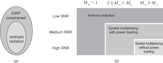
These results are summarized in Figure 15.9. Again, the points outlined above refer to precoding schemes applied on a per-subcarrier basis, and it should be highlighted that an isotropic array gain is not optimal for all EIRP-constrained systems as discussed above and in references 5, 20, and 21. This point will be elaborated on later; however, the next section focuses on the practical case where isotropic radiation is desired and per-subcarrier antenna selection is employed.
Apart from its optimality described above, per-subcarrier antenna selection is also attractive from a practical implementation perspective. At transmission, this only requires a simple switching (ON or OFF) of subcarriers at each antenna. The information required for this purpose is only the ordering of the magnitudes of channel fading coefficients from each transmit antenna to the receiver. Thus in a case where the receiver is estimating the CSI and feeding this back to the transmitter, the feedback overhead is lower compared to most other precoding methods. Furthermore, as long as the channel magnitude orders are preserved, an optimal antenna-to-subcarrier selection can be made. Perfect knowledge of the fading coefficients is not necessary. Thus, this scheme is also tolerant to errors in CSIT. In practice, CSIT is never perfectly obtained due to effects such as channel estimation errors and the inherent fluctuations of the channels with time, which causes their estimates to be outdated. Another attraction of per-subcarrier antenna selection is that the symbol detection at the receiver is (or can be made to be—c.f. Section 15.4) the same as that of a single transmit antenna system. Receiver complexity increases with most other multiple antenna transmission schemes. However, there are some practical issues to consider in applying per-subcarrier transmit antenna selection. These are discussed next.
15.4 TRANSMIT ANTENNA SELECTION
It is apparent from the above that antenna selection, although a simple transmission scheme, is a powerful method of exploiting CSIT for UWB systems. In this section, several practical aspects related to transmit antenna selection are investigated. A comparison is made between per-subcarrier and bulk selection and we explore the issue of transmit antenna selection in a manner that is compatible with legacy receivers. We also consider the issue of power amplifier efficiency optimization as well as combining peak-to-average power ratio (PAPR) reduction with antenna selection.
15.4.1 Per-Subcarrier Versus Bulk Selection
Antenna selection in OFDM systems can broadly be divided into two types: per-subcarrier and bulk selection. With per-subcarrier selection, also called per-tone selection, we choose to transmit from the best antenna on each subcarrier individually, whereas in bulk selection we choose the best antenna to transmit all subcarriers on. The advantage of per-subcarrier selection is that greater selection gains can be obtained since the frequency selectivity of the channel can be exploited. The channel on two subcarriers spaced sufficiently apart (greater than the coherence bandwidth) will be essentially independent and hence it is likely that the best antenna on those subcarriers are different. On the other hand, bulk selection means that only one antenna can be used for the whole band and for some subcarriers this means that transmission must be made on a suboptimal choice of antenna. This exploitation of frequency selectivity obviously depends on the channel characteristics. For the extreme case of a flat fading channel (no time dispersion), the two methods would have the same antenna selection. However, for larger time dispersion of the channel (more frequency selectivity), per-subcarrier antenna selection can be expected to outperform bulk selection. A performance comparison between per-subcarrier and bulk selection was done in reference 22, where it was shown that although they have the same diversity order, per-subcarrier selection has a superior coding gain.
A practical aspect of antenna selection in OFDM systems is the number of radio-frequency (RF) chains required. If per-subcarrier antenna selection is used, transmission is done on all antennas and hence the same number of RF chains is required. On the other hand, with bulk selection, only one RF chain is required since only one antenna is used for transmission. This can make it an attractive solution from a practical aspect, although there are also disadvantages. Some switching losses are associated with antenna selection of this type and there is also the issue of channel estimation. Since only one antenna is accessible at a time, some protocol must be set up to regularly switch antennas to estimate changes; this may incur delays, and outdated channel estimates could be used which degrade performance. An investigation of the implementation aspects of antenna selection in OFDM systems is done in reference 23. In the next section we will address one problem with per-subcarrier antenna selection, which is the power imbalance between the antennas that might occur if most subcarriers are chosen to be on one particular antenna.
15.4.2 Antenna Selection with Power Amplifier Efficiency Optimization
If antenna selection is done independently on each subcarrier, one antenna may have many more active subcarriers than other antennas. This is illustrated in Figure 15.10a, where the top antenna has six subcarriers allocated to it while the bottom one only has two. If the system has EIRP constraints, a maximum transmit power limit is applied to each subcarrier, which excludes power loading; hence the transmit power per antenna is proportional to the number of allocated subcarriers to transmit on. This may cause problems with the PAs because their working range must be extended to cope with cases of very large per-antenna transmit powers. An obvious solution is to reduce the power on some antennas to balance the distribution of power across all antennas. However, this would result in performance degradation, which is obviously not desirable.
Figure 15.10. Examples of per-subcarrier antenna selection, where a black box indicates that transmission will take place: (a) Unbalanced selection, where the antennas do not have the same number of subcarriers allocated to them. (b) Balanced selection, where the antennas have the same number of subcarriers allocated to them.
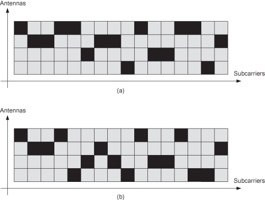
Another solution is to require the per-subcarrier antenna selection to have the same number of active subcarriers per antenna, which would result in a power balance across antennas. This is shown in Figure 15.10b. In this case, performance can be optimized with respect to some cost function subject to equal power on all antennas. If xn,m denotes the selection variable—that is, xn,m = 1 if antenna m is selected on subcarrier n, otherwise it is 0—then the constrained antenna selection problem can be formulated as an integer programming problem [24] in an OFDM system with N subcarriers and Mtx transmit antennas (it is assumed that Mtx divides N, although the same idea can be applied in the general case):
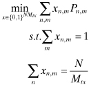
The cost Pn,m can be the BER resulting from transmitting on antenna m on subcarrier n, although other costs such as received SNR or mutual information can also be considered (which would then be maximized instead of minimized). The first constraint requires that only one antenna is transmitting on each subcarrier, while the second constraint ensures that all antennas have the same number of active subcarriers and hence the same transmit power.
This type of integer programming problem can be solved by techniques such as branch and bound or cutting planes; however, in practice the number of subcarriers is quite large, which means that the computational complexity would be high. To overcome this problem, it can be shown that the constrained antenna selection problem can be linearly relaxed without any loss of performance [25]; that is, the integer constraints on xn,m can be dropped and we may consider it as a continuous variable between zero and one. This means that the problem can be solved by much simpler linear programming algorithms, such as the simplex and interior point methods [26].
It is worth noting a few properties of the constrained antenna selection. Firstly, the BER is a better objective function than the SNR, which is proved in reference 25. The constraints force a trade-off between a small total cost and power balance, but the cost penalties are different when measured in BER or SNR. A fixed SNR difference does not mean a fixed BER difference; the relative differences are dependent upon the operating SNR region. This is an interesting observation because the choice of cost function is irrelevant in the case of unconstrained antenna selection; the selection is done independently on each subcarrier and the antenna that optimizes SNR also optimizes BER and mutual information.
15.4.3 Antenna Selection with Phase Precoding for Legacy Compatibility
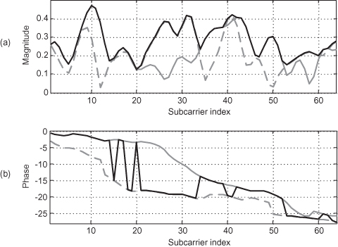
As discussed above, antenna selection applied on a per-subcarrier basis exploits the frequency selectivity of the channel to obtain diversity gains. This is illustrated in Figure 15.11a, where the magnitude of the frequency-domain channels are shown before and after antenna selection. Note that the channel after antenna selection will assume the value of one of the individual channels, hence the lines are overlapping. In TDD systems, channel knowledge at the transmitter can be obtained by the reverse channels due to the reciprocity of the wireless medium. Thus it is possible to envisage proprietary multiple antenna devices employing transmit antenna selection, which can seamlessly interact with legacy single antenna devices that do not provide the CSIT to the other end. Note that channel reciprocity is not applicable per se, since communication devices employ different radio paths for certain stages in transmission and reception. This can be addressed by calibrating transmit–receive sections of the multiple antenna device, again without any support from the legacy device at the other end.
Figure 15.11. Per-subcarrier antenna selection illustrating the channels before and after antenna selection: (a) Frequency-domain magnitude. (b) Frequency-domain phase. The two individual channel responses are shown in gray, while the channel response after antenna selection is shown in black.
In OFDM, an initial channel estimate is often obtained from a training sequence, typically in the form of a preamble (a whole OFDM symbol containing only known symbols). In this case, the receiver can be oblivious to the precoding done by the transmitter because it only estimates the compound channel (precoding plus actual propagation channel); this facilitates proprietary precoding which is compliant with the standard or is for system upgrades that must still support legacy devices. However, some care must be taken not to cause performance degradation when the receiver is unaware of the precoding.
One side effect of the per-subcarrier antenna selection is that while the magnitude of the frequency response remains reasonably smooth, the phase experiences sudden changes (see Figure 15.11b). This is natural because the antennas are selected according to their magnitude; the phase is not considered at all. This lack of smoothness might cause a problem at the receiver if some advanced channel estimation is used which exploits the frequency correlation of the channel (see, e.g., reference 27). Conventionally, the received signal on each subcarrier is divided by the known symbol in the preamble to obtain the least-squares (LS) estimate. This initial estimate can then be enhanced by exploiting the nature of the channel as explained in the following.
The OFDM system is designed to have a guard interval larger than the time dispersion of the channel. This can be exploited by transforming the LS estimate of the channel to the time domain with an inverse discrete Fourier transform. In the noiseless case, this impulse response should now be inside the length of the guard interval. Hence we can apply, for example, a windowing filter that removes everything outside this window and only keeps the signal inside. Then the time-domain estimate can be transformed back to the frequency domain with a discrete Fourier transform where the final estimate is obtained. Details about this type of time-domain (or more generally, subspace) channel estimation can be found in reference 27. Alternatively, the filtering can be done directly in the frequency domain. Since the impulse response of the channel is shorter than the length of the guard interval, which in turn is much shorter than the length of the OFDM symbol, the subcarriers will be significantly correlated. This large frequency correlation can be used to remove some of the noise by applying, for example, a Wiener filter that optimally reduces the noise. Examples of this type of filtering are given in reference 28.
However, with per-subcarrier antenna selection there will be a problem with applying these advanced channel estimation techniques. Because the phase of the channel after antenna selection will experience sudden changes, frequency-domain filtering may actually degrade the performance. This can also be viewed in the time domain: In Figure 15.12a, the magnitude of the impulse response of the channel after antenna selection is shown. It is clear that the time dispersion has been significantly increased due to the antenna selection and the impulse response is no longer contained within a small window. Hence, if windowing is applied, a large part of the channel will be removed and although the noise will be reduced, the mean-squared error (MSE) of the channel estimate will be large.
Figure 15.12. Examples of per-subcarrier antenna selection with and without phase precoding: (a) Impulse responses of the individual channels (gray) and after antenna selection (black) without phase precoding. (b) Impulse responses after antenna selection with (gray) and without (black) phase precoding. (c) Cumulative power of the impulse response with (gray) and without (black) phase precoding.
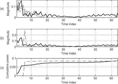
This problem can be combated with phase precoding [29]. The antenna to transmit on is chosen based on the magnitudes; the phase is not considered and can be viewed as a parameter that can be used to “smoothen” the channel response. Since the channel will be estimated at the receiver using a preamble, we can modify the phase as much as we want; it will not degrade the performance of antenna selection. Hence we select the phase on the transmitting subcarriers such that the compound channel is as smooth as possible. This means combining the phase of the actual channel with the phase of the precoding; together they should form a desirable value. One possible approach is to consider the magnitude of the compound channel as given (by the antenna selection) and then choose the phase to produce a minimum-phase signal [30]. This guarantees that the energy of the channel is maximally concentrated near the origin and hence as much energy as possible is within the guard interval window. Another approach is to use phase linearization, which aims at making the phase of the compound channel linear; the slope can be chosen by using ideas from channel shortening in equalization [31] to optimize performance. In Figure 15.12b, this technique has been used for phase precoding, where it produces a channel impulse response with reduced delay spread. This can be seen even more clearly in Figure 15.12c, where the cumulative power of the impulse response after antenna selection is shown. It is clear that phase precoding can significantly concentrate the power to a short interval, which results in better channel estimation. More crucially, phase precoding allows the benefits of per-subcarrier antenna selection to be obtained when interacting with legacy receivers.
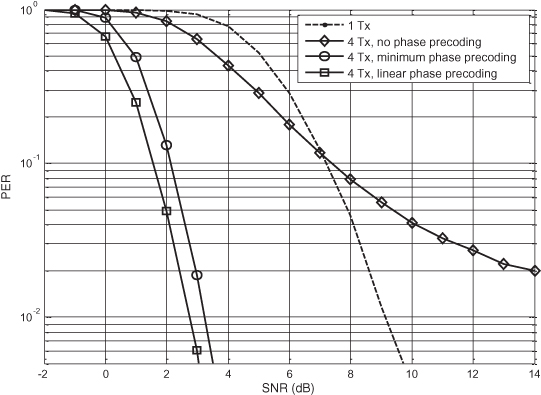
The benefits of antenna selection with phase precoding can be illustrated with an example. In Figure 15.13 the packet error rate (PER) is shown as a function of SNR for an antenna selection-based UWB system with four transmit and one receive antenna and advanced channel estimation at the receiver (for full simulation details, see reference 29). As a reference, the performance of a system with only one transmit antenna is also shown. If no phase precoding is applied, the advanced channel estimation will actually perform worse at medium-to-high SNR since the channel estimation is very poor due to the discontinuities of the frequency response of the compound channel. However, if phase precoding is applied, the performance is significantly improved and a gain of about 6 dB is observed. Linear phase is slightly better than the minimum phase precoding, indicating that the performance may be further improved by optimizing the method of phase precoding. Furthermore, it is shown in reference 29 that this proposed scheme is also robust to calibration errors in transmit–receive chains of the multiple antenna device. Thus, use of per-subcarrier antenna selection with phase precoding is suitable for link enhancement in interacting with existing TDD systems [6], which currently do not provide an explicit mechanism to provide the CSIT to the other end.
Figure 15.13. Performance with and without phase precoding in antenna selection.
As a final point, it should be noted that the constrained antenna selection described earlier may be combined with the phase precoding if advanced channel estimation is desirable at the receiver.
15.4.4 PAPR Reduction in Antenna Selection Systems
All OFDM transmissions suffer from a high PAPR, a problem that can lead to power amplifier (PA) inefficiencies and distortion of the transmitted signal. This problem results from the linear combination of modulated data signals prior to transmission, which is performed by the IDFT. A significant amount of research has been devoted to reducing the PAPR of OFDM signals in the past decade. The most straightforward method consists of applying a back-off to the PA output, which is clearly undesirable from an efficiency point of view. Other techniques for mitigating the PAPR problem in OFDM transmissions include active constellation extension (ACE), tone injection (TI), and tone reservation (TR), to name a few [32]. In particular, TR is a promising technique that is based on reserving a subset of subcarriers from data transmission, instead opting to excite these subcarriers, which are termed peak reduction carriers, in such a way as to reduce the PAPR of the transmitted signal. The peak reduction signals can be designed in a number of ways, such as by executing an exhaustive search over a finite set of possible signals to find the signal that minimizes the PAPR or by implementing a gradient descent algorithm to find the (nearly) optimal signal.
Peak reduction signals do not carry information, and thus the implementation of conventional TR algorithms leads to a reduction in throughput. However, for multi-antenna systems employing per-subcarrier antenna selection, an opportunistic TR strategy has been developed that makes use of “bad” subcarriers (as seen by a particular antenna) to transmit peak reduction signals [33]. In this scheme, antenna selection is first performed according to some optimization strategy, such as the balanced technique described above. At the end of the selection process, a single antenna will have been allocated for data transmission on each subcarrier. In the opportunistic TR scheme, peak reduction signals are designed and transmitted from a subset of the remaining “inactive” antennas. Note that since data are still transmitted on each subcarrier, this TR strategy is rate lossless. Figure 15.14 illustrates the allocation of peak reduction carriers to inactive antennas across an OFDM symbol with eight subcarriers.
Figure 15.14. Illustration of opportunistic PAPR reduction in OFDM systems employing per-subcarrier antenna selection.
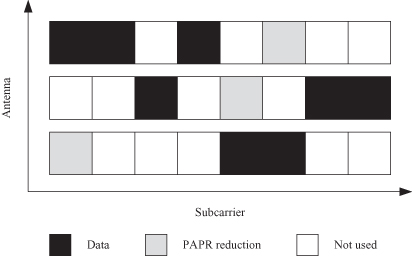
It is evident from the description above, as well as from Figure 15.14, that the peak reduction signals will interfere with the data signals at the receiver, which will lead to degradation in performance. Crucially, the peak reduction signals are transmitted on “bad” channels—that is, channels with a large attenuation, a condition that results from the initial antenna selection process. When these channels exhibit severe fading characteristics, the peak reduction signals are heavily attenuated and thus cause minimal interference to the received data signal. Of course, the severity of the interference depends on a number of factors, including the fading statistics of the channel, the number of peak reduction signals, and the power that is allocated to each of these signals. Interestingly, it has been shown that the performance degradation due to interference can be made arbitrarily small by limiting the peak reduction signal power, even if a large number of subcarriers are used for peak reduction [33]. Moreover, the reduction in PAPR that can be achieved with this approach is on the order of several decibels.
15.5 TRANSMIT BEAMFORMING IN UWB SYSTEMS
In this section, we consider the conditioning of transmit signals to improve the received SNR in UWB communication systems.
15.5.1 Conventional Beamforming Approaches
Conventionally, the term “beamforming” is associated with the adjustment of transmit signals in order to effect the transmitted spatial radiation such that some measure related to the received SNR is optimized. Such spatial beamforming of transmit signals is a widely investigated topic and has found application, for example, in signal transmission from cellular base stations to mobile devices [34]. The idea is to first identify the spatial directions of individual mobile users and then properly direct the transmissions from the base stations such that the received signals of the users are optimized.
Alternatively, it is also possible to beamform purely in the domain of baseband signal processing. Here, the channels are viewed based on the fading coefficients as seen in the baseband, and the transmit signals are suitably optimized. Identification of the corresponding optimal beamforming vectors simplifies for systems with a total transmit power constraint. Essentially, it is optimal to transmit on the channel eigenmode corresponding to the largest eigenvalue of the MIMO channel matrix. Such transmission schemes are known as eigenbeamforming. While such eigenbeamformed transmissions do not explicitly take into account the spatial direction of the receiver, they do result in spatially directed transmissions that are matched to the baseband channel.
15.5.2 Transmit Beamforming with EIRP Constraints
Let us now focus on the case where transmit beamforming is used to improve the received SNR in UWB systems. Again, the difference to conventional beamforming is the existence of EIRP restrictions rather than total transmit power constraints. Similar to the case of capacity optimal transmissions, it turns out that received SNR optimal transmission schemes for UWB systems do not lead to isotropic radiation in general. Had it been so, transmit antenna selection would have been the EIRP optimal beamforming method. Interestingly, even eigenbeamforming is not optimal for these EIRP-constrained systems. Due to the high directivity of transmissions from eigenbeamforming, the transmit power must be backed off (i.e., scaled) to satisfy the EIRP restrictions, resulting in a substantial performance degradation.
It can be shown that the optimal beamforming scheme for systems with EIRP restrictions can be formulated as the solution to a convex optimization problem [21]. However, numerical solutions necessary for this optimal method suffer from high computational complexity since an optimization over a complicated region in a multidimensional space is required. Conventional suboptimal methods, such as transmit antenna selection and use of eigenbeamforming scaled to satisfy the EIRP restrictions, require lower computational complexity at the expense of a degradation in performance [5, 21].
Figure 15.15 illustrates the radiation patterns due to various transmit beamforming methods for a particular channel realization. Transmit antenna selection leads to an isotropic array effect. Generally, the following properties of the radiation due to the optimal scheme can be observed:
Figure 15.15. Radiation patterns due to some transmit beamforming methods.
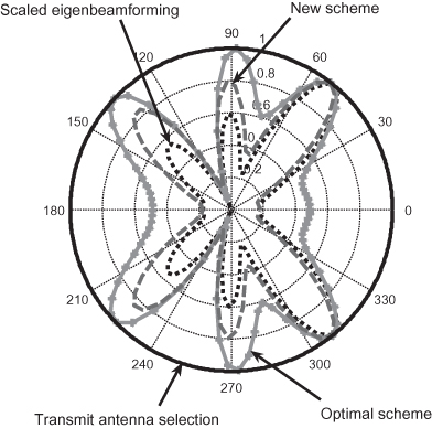
- It resembles the radiation due to scaled eigenbeamforming.
- Compared to scaled eigenbeamforming, it has a lower spatial PAPR, while the directions of peak radiation are approximately preserved.
- For particular channel realizations, it reduces to transmit antenna selection.
Essentially, it appears that the scaled eigenbeamforming solution does not fully exploit the fact that it is the EIRP that is restricted rather than the total transmit power. The optimal scheme attempts to rectify this. These observations form the basis of a transmit beamforming methodology for EIRP-constrained systems, as explained with more detail in reference 35. Following the observations given above, it is possible to develop a beamforming scheme with the objective of designing beamforming vectors by perturbing the scaled eigenbeamforming vector such that (a) the PAPR of its spatial radiation is reduced and (b) its direction of peak radiation is approximately preserved.
When the transmitter consists of a linear array of antennas, samples of the spatial radiation are given by the IDFT of the beamforming vector. The problem of reducing the spatial PAPR of the radiation therefore becomes similar to PAPR reduction of the time-domain OFDM signals (which was discussed earlier), where many algorithms have been proposed [32]. However, these algorithms do not necessarily preserve the direction of the peak radiation in their attempts at PAPR reduction, and therefore they will yield inferior performance when directly applied to beamforming vector design. In reference 35, this issue was addressed by introducing phase adjustments, which ensure that the IDFT operations sample the direction of peak radiation, thereby facilitating its preservation. For the task of spatial PAPR reduction itself, many of the algorithms found in the OFDM literature, such as the iterative soft-clipping and filtering method, can be adopted.
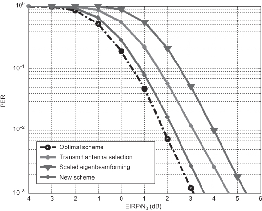
The PER performance of this new scheme, when implemented with the iterative soft-clipping and filtering method for PAPR reduction, is illustrated in Figure 15.16, where a system with four transmit antennas and one receive antenna is considered. The simulated channels correspond to the IEEE 802.15.3a channel model CM3. For further details of the simulation setup, please refer to reference 35. It can be observed that at a PER of 10−3, antenna selection is more than 1.5 dB suboptimal, while the performance of the proposed beamforming method is only 0.5 dB inferior compared to the optimal scheme. The performance using the scaled eigenbeamforming vector, however, is about 2.5 dB suboptimal, due to the power back-off required to satisfy the EIRP restrictions.
Figure 15.16. PER performance of some EIRP-constrained beamforming schemes.
15.6 SUMMARY
Exploitation of CSIT in multiple transmit antenna equipped UWB systems was considered in this chapter. An investigation of capacity-optimal precoding reveals that with only two transmit antennas, it is optimal to employ a spatial multiplexing scheme with a power allocation across the antennas, on each of the subcarriers. The power allocations represent the freedom to exploit the CSIT. For the cases of low SNR or when there is only a single receive antenna, this power allocation reduces to antenna selection, performed on each of the subcarriers.
Per-subcarrier antenna selection is also attractive as a general precoding method for EIRP-constrained systems due to its practicality. It was shown that antenna selection coupled with phase precoding can be used to design legacy ECMA368 compatible transmission schemes that can give significant performance improvements over conventional systems. Also, antenna selection can be performed to improve link performance while ensuring that the transmit power is evenly distributed across all transmit antennas. This optimizes the efficiency of power amplifiers used on the individual transmit antennas. The absence of signals in some of the subcarriers also allows these transmissions to send additional signals purely for the purpose of alleviating PAPR issues associated with OFDM transmit signals.
Finally, noting that per-subcarrier antenna selection is not the received SNR optimal beamforming scheme in general, existences of better transmit beamforming schemes were illustrated. In summary, one can conclude that precoding is a promising practical method of achieving robust, high-rate communication in UWB networks, despite the strict regulatory limitations on the transmissions.
ACKNOWLEDGMENT
The authors would like to acknowledge the fruitful discussions with their colleagues at Toshiba Research Europe and the support of its directors.
Notes
* This chapter is based on “Precoding in OFDM-based multi-antenna ultra-wideband systems,” by C. Vithanage, M. Sandell, J. Coon, and Y. Wang, which appeared in the IEEE Communications Magazine, January 2009. © 2009 IEEE.
1 Traditionally, the term beamforming has been related to the manipulation of radiation patterns in the spatial sense, while precoding has been related to a baseband processing of data taking into account the channel state information. In the modern era of digital communication, precoding can be used to achieve beamforming; thus, these two terms are used interchangeably throughout this chapter.
2 This chapter makes frequent references to the capacity of a channel. Following the pioneering work of Shannon [37], this refers to the maximum error-free data transmission rate supported by the channel. In a nutshell, the mutual information between some transmit signal and the corresponding signal received through the channel indicates the largest error-free data rate supported for that particular transmit signal. Optimization over all possible transmit signals then leads to the maximization of such mutual information, which is the channel capacity. p. 566
3 MB-OFDM was, perhaps, most famously adopted by a consortium of companies known as the WiMedia Alliance, which focused on building upon the ECMA 368 standard. However, following the financial troubles that plagued the international community at the end of 2008, the WiMedia Alliance disbanded, and the work of that group was absorbed into the Bluetooth SIG [36].
REFERENCES
1. Federal Communications Commission, Title 47, Section 15, Code of Federal Regulations.
2. Federal Communications Commission, First report and order, revision of part 15 of the commission’s rules regarding ultra-wideband transmission systems, ET Docket 98-153, February 2002.
3. C. Razzell, J. Yang, and D. Birru, Approaches and considerations for evolution of OFDM-based UWB PHY solutions beyond 1 Gbps, in IEEE International Conference on Ultra-Wideband (ICUWB), Singapore, 2007.
4. T. K. Paul and T. Ogunfunmi, Wireless LAN comes of age: Understanding the IEEE 802.11n amendment, IEEE Circuits Systems Mag., Vol. 8, No. 1, pp. 28–54, 2008.
5. A. M. Kuzminsky, Downlink beamforming subject to the equivalent isotropic radiated power constraint in WLAN OFDM systems, Signal Processing, Vol. 87, No. 5, pp. 991–1002, May 2007.
6. ECMA, ECMA368: High Rate Ultra Wideband PHY and MAC Standard, December 3, 2008.
7. I. Oppermann, M. Hämäläinen, and J. Iinatti (editors), UWB: Theory and Applications, John Wiley & Sons, Chichester, 2004.
8. J. Zhang et al., UWB systems for wireless sensor networks, Proc. IEEE, Vol. 97, No. 2, pp. 313–331, February 2009.
9. R. W. Chang, Synthesis of band-limited orthogonal signals for multi-channel data transmission, Bell System Technical J., No. 46, pp. 1775–1796, 1966.
10. R. van Nee and R. Prasad, OFDM for Wireless Multimedia Communications, Artech House, Norwood, MA, 2000.
11. J. Wang and W. T. Tung, Narrowband interference suppression in time-hopping impulse radio ultra-wideband communications, IEEE Trans. Commun., Vol. 54, No. 6, pp. 1057–1067, June 2006.
12. Y. Wang, X. Dong, and I. J. Fair, Spectrum shaping and NBI suppression in UWB communications, IEEE Trans. Wireless Commun., Vol. 6, No. 5, pp. 1944–1952, May 2007.
13. J. Balakrishna and H. Yamaguchi, Ultra wideband interference cancellation for orthogonal frequency division multiplex transmitters by protection-edge tones, 2006. US Patent US 2006/0008016 A1.
14. Y. Wang and J. Coon, Active interference cancellation for systems with antenna selection, in IEEE International Conference on Communications, Beijing, 2008, pp. 3785–3789.
15. G. J. Foschini and M. Gans, On limits of wireless communications in a fading environment when using multiple antennas, Wireless Personal Commun., Vol. 6, No. 3, pp. 311–355, March 1998.
16. E. Telatar, Capacity of multi-antenna Gaussian channels, Eur. Trans. Telecommun., Vol. 10, No. 6, pp. 585–596, 1999.
17. S. M. Alamouti, A simple transmit diversity technique for wireless communications, IEEE J. Select Areas Commun., Vol. 16, No. 8, pp. 1451–1458, October 1998.
18. G. L. Stuber et al., Broadband MIMO-OFDM wireless communications, Proc. IEEE, Vol. 92, No. 2, pp. 271–294, February 2004.
19. C. A. Balanis, Antenna Theory, John Wiley & Sons, Toronto, 1997.
20. C. M. Vithanage, J. P. Coon, and S. C. J. Parker, On capacity-optimal precoding for multiple antenna systems subject to EIRP restrictions, IEEE Trans. Wireless Commun., Vol. 7, No. 12, part 2, pp. 5182–5187, December 2008.
21. P. Zetterberg et al., Performance of multiple-receive multiple-transmit beamforming in WLAN-type systems under power or EIRP constraints with delayed channel estimates, in IEEE Vehicular Technology Conference (VTC Spring), Vol. 4, Birmingham, 2002, pp. 1906–1910.
22. H. Zhang and R. Nabar, Transmit antenna selection in MIMO-OFDM systems: Bulk versus per-tone selection, in International Conference on Communications (ICC), IEEE, Beijing, 2008, pp. 4371–4375.
23. A. Molisch et al., Implementation aspects of antenna selection for MIMO systems, in International Conference on Communications and Networking in China (ChinaCom), ICST, Beijing, 2006, pp. 1–7.
24. L. Wolsey, Integer Programming, John Wiley & Sons, New York, 1998.
25. M. Sandell and J. Coon, Per-subcarrier antenna selection with power constraints in OFDM systems, IEEE Trans. Wireless Commun., Vol. 8, No. 2, pp. 673–677, February 2009.
26. S. Boyd and L. Vandenbergh, Convex Optimization, Cambridge University Press, Cambridge, 2004.
27. O. Edfors et al., OFDM channel estimation by singular value decomposition, IEEE Trans. Commun., Vol. 46, No. 7, pp. 931–939, July 1998.
28. T. Onizawa et al., A simple adaptive channel estimation scheme for OFDM systems, in Vehicular Technology Conference (VTC Fall), Vol. 1, IEEE, Amsterdam, 1999, pp. 279–283.
29. C. M. Vithanage, S. C. J. Parker, and M. Sandell, Antenna selection with phase precoding for high performance UWB communication with legacy WiMedia multiband OFDM devices, International Conference on Communications (ICC), IEEE, Beijing, 2008, pp. 3938–3942.
30. A. W. Oppenheim and R. W. Schafer, Discrete-Time Signal Processing, Prentice-Hall, Englewood Cliffs, NJ, 1989.
31. N. Al-Dhahir, FIR channel shortening equalizers for MIMO ISI channels, IEEE Trans. Commun., Vol. 49, No. 2, pp. 213–218, February 2001.
32. S. H. Han and J. H. Lee, An overview of peak-to-average power ratio reduction techniques for multicarrier transmission, IEEE Wireless Commun., Vol. 12, No. 2, pp. 56–65, April 2005.
33. J. P. Coon, PAPR reduction in OFDM systems with per-subcarrier antenna selection, in IEEE Wireless Communication Networking Conference, 2009.
34. L. C. Godara, Application of antenna arrays to mobile communications, Part II: Beam forming and direction-of-arrival considerations, Proc. IEEE, Vol. 85, No. 8, pp. 1195–1245, August 1997.
35. C. M. Vithanage, Y. Wang, and J. P. Coon, Spatial PAPR reduction based beamforming scheme for EIRP constrained systems, in Global Telecommunications Conference (Globecom), IEEE, New Orleans, 2008, pp. 1–5.
36. WiMedia Alliance, Multiband OFDM Physical Layer Specification, WiMedia Alliance, 2005.
37. C. E. Shannon, A mathematical theory of communication, Bell System Tech. J., Vol. 27, pp. 379–423, 623–656, July, October 1948.