
Part IV: METROPOLITAN, CORE, AND STORAGE AREA NETWORKS
16
NEXT-GENERATION INTEGRATED METROPOLITAN-ACCESS NETWORK: TECHNOLOGY INTEGRATION AND WIRELESS CONVERGENCE
Since the past decade, broadband access networks have undergone significant changes. Fiber optics is reaching to homes, and wireless data access networks are becoming ubiquitous. As emerging multimedia applications continue to demand for larger bandwidth, the evolution of broadband access networks is expected to remain. As a result, next-generation metropolitan area networks must be able to support the architectural changes and growing traffic demands of emerging broadband access infrastructures. The integration between metropolitan and access networks is becoming a promising solution for future networks to accommodate these challenges. This chapter exploits future integrated metropolitan-access network architectures that can seamlessly support high-bandwidth, pervasive applications to come.
In this chapter, we first review important recent developments in metropolitan and access networks. With this foundation, the integration of metropolitan and optical access networks is discussed in some detail, with focus on the trade-offs between integrated and nonintegrated metro-access solutions. We then examine the convergence of optical and wireless access networks as a solution to overcome the bandwidth and coverage limitations of current broadband access networks. A number of examples are included in the chapter to demonstrate how next-generation networks can meet the emerging traffic challenges and gracefully evolve from existing networks. A future direction of integrated metro-access networks concludes the chapter.
16.1 RECENT DEVELOPMENTS IN METROPOLITAN AND ACCESS NETWORKS
16.1.1 Metropolitan Area Networks
16.1.1.1 SONET/SDH: Metropolitan Ring Network and Flexible Adaptation of Data Traffic.
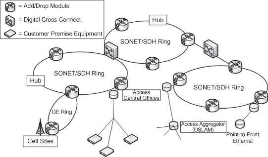
Initially, metropolitan area networks (MANs) have predominantly relied on interconnected rings (as shown in Figure 16.1) based on the Synchronous Optical Network (SONET) hierarchy, which was standardized in the United States in the late 1980s. SONET is closely related to Synchronous Digital Hierarchy (SDH), the standard proposed almost simultaneously in Europe. SONET/SDH networks are typically deployed in rings, because this topology allows survivability of connections upon the occurrence of a single failure, such as a fiber cut, at the expense of some efficiency loss. SONET/SDH ring nodes are composed of add/drop multiplexers (ADMs), whose primary function is to electronically aggregate traffic into the fiber and drop tributary lower-speed traffic destined for the node. SONET/SDH networks still represent a significant share of the current service providers’ infrastructure [1].
Figure 16.1. Metropolitan and access network (MAN) architecture.
The SONET/SDH standards emerged mainly as a transport mechanism for carrying a large number of plesiochronous digital hierarchy (PDH) payloads, which are comprised of several lower-speed digitized-voice signals. Because the voice traffic represented the major service SONET/SDH networks initially were designed to support, the SONET/SDH standards were built on a time-division multiplexing (TDM) circuit-switched hierarchy with a synchronous frame structure for the transport of digital-voice traffic. The key attribute of circuit-switched networks is the existence of a fixed, guaranteed bandwidth circuit in all links between the source and destination nodes before they may communicate.
Recently, SONET/SDH networks incorporated mechanisms for mapping generic data transport protocols into the synchronous frames. This was motivated by the fact that whereas the growth of the voice traffic was smooth since the introduction of the first SONET/SDH metro optical networks, the Internet traffic was increasing very rapidly, close to doubling every year since 1997 [2]. Although SONET/SDH networks can be combined with the wavelength division multiplexing (WDM) technology to scale up their transmission capacity due to the aggregation of access traffic, the variety of services and types of traffic presented in today’s metro networks require a more efficient usage of the bandwidth than that provided by TDM circuits. This is because the capacity of the payload was rigidly defined to accommodate PDH streams. The limited number of protocols that could be mapped into SONET/SDH frames did not reflect the emergence of new technologies for transporting data in the metro segment, especially 100 Mbits Ethernet and Gigabit Ethernet. In order to define an efficient and interoperable mapping of generic protocols in SONET/SDH networks, the International Telecommunication Union (ITU) defined the Generic Framing Procedure (GFP) [3] in 2001. To provide SONET/SDH systems with high efficiency in the accommodation of a variety of protocols, GFP must be combined with two other technologies [4]:
(a) Virtual Concatenation (VCAT). VCAT defines a mechanism for carrying payloads with flexible bandwidth, which is a desirable feature for transporting data service; the payload is comprised of a virtual concatenation of several smaller payloads that are separately carried from the source to destination terminals and eventually combined to reconstruct the original payload at the destination.
(b) Link Capacity Adjustment Scheme (LCAS). LCAS dynamically uses VCAT to enable efficient transport of generic formats by allowing the number of concatenated payloads to be changed dynamically. The SONET/SDH networks that incorporate data traffic adaptation features have been referred to as next-generation SONET/SDH systems.
16.1.1.2 Resilient Packet Ring.
Resilient Packet Ring (RPR) is a ring-topology network architecture designed to provide packet-aware service provisioning in optical fiber ring networks such as SONET/SDH [5]. RPR aims at combining SONET/SDH’s resilience and reliability functionalities with Ethernet’s simplicity, low-cost, and efficient bandwidth utilization. The choice of a ring topology allows for fast protection switching (within 50 ms) upon the occurrence of a single link or node failure, whereas the definition of a medium access control (MAC) protocol with a client interface similar to Ethernet’s improves the bandwidth utilization of the optical fiber ring. RPR works on a dual-ring configuration in which each ring is called a ringlet. The ringlets are set up by the creation of RPR stations at the network nodes. RPR enables spatial reuse within the ring, since the receiving RPR station completely removes its received packet from the ring rather than replicating its content and sending it back to the sender [5]. This feature, often referred to as destination stripping, allows the released bandwidth to be used for carrying additional traffic if needed. Moreover, in contrast to traditional SONET/SDH rings in which the backup ring is only utilized when the primary ring fails, RPR makes full use of the bandwidth of both counterdirectional fiber rings under no-fail operation.
The RPR architecture provides class of service support and can bridge to Ethernet with fairness. RPR gives priority to transit traffic over the traffic a station is ready to add, and guarantees that no in-transit traffic is lost. To maintain this lossless property, RPR relies on a fairness control that reduces the amount of admissible transmit traffic during high transit flows. The objective of the fairness control is to distribute a fair traffic insertion rate among congested RPR stations. However, it is known that the RPR fairness control may not always reach a steady state under many realistic traffic scenarios. This problem significantly underutilizes the useable part of RPR bandwidth during fairness rate oscillation [6]. Current RPR standard assumes single-channel networks and does not provide yet a clear guideline for a WDM upgrade. Emerging integrated metro-access architectures should preserve the beneficial properties of RPR, including protection, spatial reuse, QoS support, fairness, and introduce more stable bandwidth utilization and scalability features through a multi channel WDM layer.
16.1.1.3 G.709 Optical Transport Network.
The Optical Transport Network (OTN) is a recently proposed standard to meet metro-optical network convergence of wide-ranging services in a common platform [7]. OTN consists of a multiservice transport architecture that transparently supports packet-based data transport as well as SONET/SDH circuits over a dense wavelength division multiplexing (DWDM) layer. The main functionality of OTN is its “digital wrapper” technology, which provides a mechanism for encapsulating a number of existing frames into an entity that can be successfully transported with a small amount of overhead and forward error correction (FEC) bytes. Essentially, client traffic of any protocol can be wrapped into a frame that carries information about both the client and the optical wavelength it uses as transport medium. Moreover, this protocol-agnostic, digital wrapper technology provides an upper layer that allows end-to-end monitoring of connections, even if they traverse several networks from different service providers with different SLAs. In summary, the digital wrapping mechanism provides intelligence and OAM capabilities to optical wavelengths, leading to a scalable platform capable of carrying a number of protocols with almost all benefits of the SONET/SDH performance management. Initial clients of OTN were predominantly SONET/SDH signals, but data clients like Ethernet and IP are increasingly being transported over this converging platform.
The key elements of the DWDM layer are the fixed optical add/drop multiplexers (OADMs), whose function is to statically add and drop traffic in the wavelength granularity and bypass wavelengths in the optical domain [7, 8]. Most of the OADMs are built with fixed optical filters, which are inserted within the optical path along the ring to add and/or drop pre-determined wavelengths. OADM nodes based on fixed optical filters may be considered a very cost-effective mechanism to access the optical spectrum within a WDM signal, as these nodes are easily designed and deployed. However, the main disadvantage of a solution based on fixed optical filters is the requirement of significant information about the expected traffic growth in the network. Eventual traffic reallocations require the insertion of additional optical filters within the signal path, a procedure that cannot be performed without traffic interruption and the presence of trained personnel in the node site. Moreover, in situations where an unforeseen traffic demand surpasses the traffic expectations in some network location, the lack of flexibility of fixed OADMs prevents the reallocation of unused optical spectrum to support this demand. The novel integrated metropolitan-access architectures presented in this chapter address these problems by making use of a reconfigurable optical layer, which is discussed in the next subsection.
16.1.1.4 ROADM and Reconfigurability.
The reconfigurable OADM (ROADM), whose advent resulted from recent developments of optical technologies [9], is an alternative solution to overcome the absence of flexibility of fixed OADMs. In essence, ROADMs are network elements that enable an automated optical layer by allowing dynamic wavelength add/drop functionality within a WDM signal. ROADMs are capable of offering fast wavelength service provisioning and are the key elements for the emerging dynamic WDM networks in metropolitan environments [8, 10]. Such dynamic WDM MANs must be characterized by fast optical circuit provisioning (namely, fast optical circuit switching, OCS), in contrast to sporadic connection requests that can be successfully accomplished by SONET/SDH, OTN, or point-to-point optical Ethernet transmission systems. As a result, the rapid establishment of wavelength services will be severely dependent on the ROADM switching times, which are on the order of milliseconds with current optical component technology. Moreover, driven by the emergence of new optical switching techniques for future metropolitan environments such as optical burst switching (OBS), ROADM switching times will have to be as low as a few microseconds or even nanoseconds to successfully accomplish the switching of an optical burst or packet [11].
In this chapter, new integrated metro-access architectures based on alternative solutions to ROADMs are presented. Such alternative solutions employ fast tunable transceivers to enable reconfigurability. Tunable transceivers place reconfigurability at the source and/or destination terminals, allowing transmission from the source to destination without intermediate switching. Moreover, this type of architecture allows smooth WDM upgrade without requiring changes at intermediate nodes. Current tunable transceivers can typically switch under a microsecond, and some recent demonstrations have reported switching times within the nanosecond range [12, 13]. As a result, networks that employ such fast tunable transceivers can usually achieve high flexibility.
16.1.2 Broadband Access Networks
16.1.2.1 Passive Optical Network.
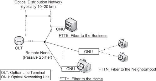
A passive optical network (PON) is a low cost fiber-optic network designed to provide broadband fiber access to end users. In general, PON systems employ a point-to-multi point architecture that consists of an optical line terminal (OLT), a remote node (RN), and several optical network units (ONUs). A PON employs a passive RN in its optical distribution network (ODN) to lower capital and operational expenditure (CAPEX/OPEX) requirements. Figure 16.2 illustrates the generic PON architecture. The terminology FTTx refers to where the optical fiber termination is located. Some common examples are FTTH (fiber-to-the-home), FTTN (fiber-to-the-neighborhood), and FTTB (fiber-to-the-business).
Figure 16.2. Passive optical network (PON) architecture.
Currently deployed PONs are based on three dominating standards, all of them TDM-based: Broadband PON (BPON), Gigabit-capable PON (GPON), and Ethernet PON (EPON). A TDM-PON typically supports between 16 and 64 users, and its physical-layer (PHY) rates can support up to 2.488-Gbps downstream and 1.244-Gbits upstream traffic. The key characteristics and differences between these three current-generation optical access networks are summarized in Table 16.1. Overall, each standard differs primarily in their protocol adaptations and offered bitrates. In essence, they share similar operating principles. Without loss of generality, this chapter focuses on EPON technology.
TABLE 16.1. TDM-PON Comparison
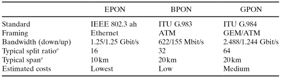
aSplit-ratio and span combination depends on the supported optical budget.
Anticipating the growth of demand for bandwidth, both the ITU-T and IEEE standardization bodies are studying options to expand the capacity of current TDM-PONs. Table 16.2 summarizes three standardized upgrading approaches: line rate enhancement, WDM enhancement, and physical reach extension. These standard activities are also summarized in Section 16.4. The key challenge in upgrading a TDM-PON is the ability to make incremental upgrades over an existing ODN—that is by using a pay-as-you-grow strategy. Such an evolution strategy reduces the occurrence of service disruption and delays capital expenses to only when they become necessary. Section 16.2 presents a detailed discussion about integrated metro-access networks as an evolutionary framework to enable smooth and flexible expansion towards next-generation access networks.
TABLE 16.2. Next-Generation PON (NG-PON) Comparison
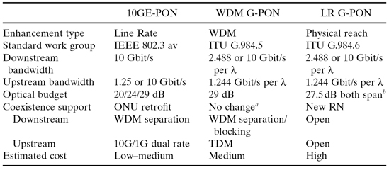
aITU G.984.5 recommends addition of wavelength blocking filter at ONU during initial deployment.
bAn active mid-span extender would allow the optical line to be extended to a total of 60 km.
16.1.2.2 Wireless Broadband Access Network.
This chapter focuses on wireless broadband Internet access technologies. In particular, wireless broadband networks such as Worldwide Interoperability for Microwave Access (WiMAX) and Wireless Fidelity (WiFi) access systems are considered.
In general, WiMAX is a wireless broadband access technology based on a subset of profiles recommended by the IEEE 802.16 standards. WiMAX systems can operate in several modes, and this chapter considers the 802.16 time division duplex (TDD) mode without multiple hop extension. WiFi is a system based on IEEE 802.11-standards and is mostly used in wireless local area networks (WLANs). For the purpose of this chapter, we restrict our analysis to the IEEE 802.11s-based wireless mesh networks (WMNs) due to their suitability for large-scale deployment.
16.1.2.3 Convergence of Optical and Wireless Access Network.
As wireless technology has become more popular with ever-increasing quality attributes, telecom operators are interested in supporting services with QoS requirements in their core mobile segment. Smooth cooperation between the wireline and wireless networks is necessary to facilitate the support of wireline-like services over wireless networks. For this reason, the Fixed-Mobile Convergence (FMC) Alliance [14] was formed in 2004 to address the convergence between wireline and wireless service network. FMC was initially established to study the convergence between PSTN (Public Switched Telephone Network) and PLMN (Public Land Mobile Network) networks. Recently, FMC has been also expanding and considering the integration with broadband wireline networks such as FTTx. However, it focuses on the application layer and incorporates a session initiation protocol (SIP) to provide high-capacity and seamless connection across fixed and mobile networks. Section 16.4 summarizes the FMC’s efforts to integrate fiber and wireless network using an application layer convergence.
In Section 16.3, a new trend called optical-wireless integration (OWI) is presented. OWI is expected to provide FMC service by exploring complementary characteristics between optical and wireless networks. Whereas optical networks are robust and offer high bandwidth, wireless networks support mobility and ubiquitous coverage. In particular, new designs of metropolitan area networks are presented to provide a backbone for large-scale broadband wireless access networks. Moreover, readers are introduced to a new integrated control framework to enhance existing wireless network performance.
16.2 METROPOLITAN AREA AND BROADBAND ACCESS NETWORK INTEGRATION
Future broadband access networks are expected to support ever-increasing demands from end users, and metropolitan area networks must employ architectures that can gracefully scale up with the growing volume of access traffic. In this context, efficient traffic aggregation and transparent optical transmission are desirable features for future MANs, since they alleviate the scalability problem in backbone networks. For this purpose, two promising architectures for future optical MANs are presented in this section. The first architecture is optical burst transport (OBT), which provides an effective mechanism to groom bursty traffic at transmit nodes and employs optical bypassing to efficiently manage aggregated traffic without opto-electro-optical (OEO) conversion at intermediate nodes. OBT is a ring-based adaptation of optical burst switching (OBS), but it has its own characteristics, as presented in Section 16.2.1. The second architecture is metropolitan-access ring integrated network (MARIN). MARIN is an integrated architecture that can seamlessly combine the metropolitan network with the access network. Unlike in OBT, in MARIN only the source and destination nodes are involved in the transmission, and there is no switching in intermediate nodes. This is an important feature for access integration because intermediate nodes in optical access networks are desired to remain passive.
16.2.1 Optical Burst Transport Technology
The basis of OBT is to accommodate bursty data traffic using burst mode transmission and fast optical switches. Like in OBS, the transmission in OBT is initiated after a control header is sent to the destination node to set up a lightpath that remains active until the transmission ceases. Control signals in the OBT network use a dedicated control channel, and they are processed at every node. Once the transmission is initiated, there is no switching at intermediate nodes, and data bursts see a single optical hop between the source and destination nodes within a given data channel. Each data channel is specified by a wavelength. Figure 16.3a illustrates the architecture of the OBT network proposed by [15].
Figure 16.3. (a) Optical burst transport (OBT) network architecture. (b) Example of OBT wavelength token and burst control protocol.
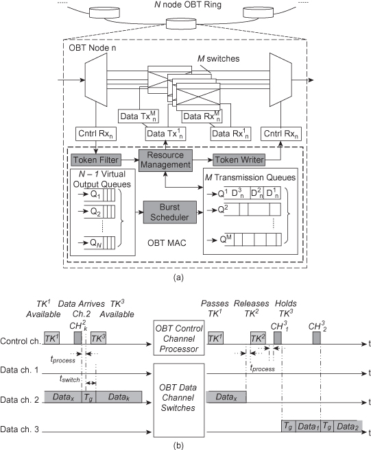
16.2.1.1 OBT Protocol.
OBT requires an appropriate medium access control (MAC) in order to avoid collision among the various data paths that can be established from source to destination nodes. To this end, OBT uses tokens to allocate transmission bandwidth among the nodes. Another approach for evenly sharing the medium could be a timeslotted WDM ring that uses an optical supervisory channel (OSC) to control the use of time slots. Such a timeslotted WDM ring has been shown to outperform the token WDM ring when the network data rate increases [16]. However, OBT does not employ an OSC because its use requires strict synchronization between the control and data channels. Since synchronization is a challenge in a WDM network due to group velocity dispersion (GVD), each data channel would have a time offset with respect to the OSC. Using a token control, OBT sacrifices some bandwidth utilization because it does not allow immediate channel access, but it avoids the GVD problem. Token access further enables flexibility to adapt variable size Ethernet packet and provides fairness using limitation on holding times.
Figure 16.3b illustrates the OBT protocol through an example. In this example, the node passes the first data token—that is, TK1 (for channel 1)—because it has not accumulated enough data at the time it sees the token. At the arrival of the second data token, TK3, it accumulates enough data and holds onto the third wavelength channel. Traffic is groomed in virtual output queues (VOQ) according to its destination node. The transmit node can send a burst with several sub-bursts, each one addressed to a different destination. A constant offset time is inserted between control header and the first sub-burst. The length of the offset time is determined by the time to configure the lightpath and process the control packets. Under the OBT architecture, the amount of time required to configure a lightpath is around 260 ns, which is made possible by an ultra fast switch such as the (Pb,La)(Zr,Ti)O3-based switch. The 1 × 2 PLZT switch has reported less than 2.5-ns switching times [17].
16.2.1.2 Spatial Reuse.
OBT employs spatial reuse to enhance its bandwidth utilization. This is possible because OBT drops receiving bursts at the destination, leaving the data path from the destination to the source unused. This path could be reused for secondary transmission when the primary transmission takes place between source and destination. Collision is not a concern since wavelength token is held by the source. Thus, it is possible for a node to initiate secondary transmission upon receiving a control channel indicating it as the destination. The length of this secondary transmission is determined by the duration of the sub-burst and the node can utilize the data path up to this duration, minus the guard time and processing time. The performance of spatial reuse in OBT is shown in [18] and the results showed nearly 100% throughput enhancement over OBT without spatial reuse.
16.2.1.3 Traffic Grooming.
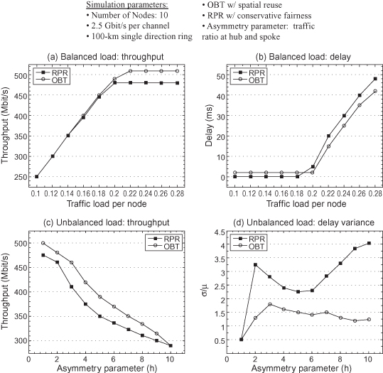
OBT provides robust sub-lambda granularity by aggregating and grooming individual data into singular wavelength bursts. Because the burst size can be adjusted dynamically, OBT can adapt to either circuit-oriented or data-oriented services. Figure 16.4 shows the comparative performance between OBT and RPR under single channel operation using simulation. Figure 16.4a shows that under balanced traffic load, OBT and RPR have similar throughput performance. OBT outperforms RPR during high network load because RPR transmit traffic has strictly lower priority than its transit traffic [5, 19], [5]. Figure 16.4b shows that RPR outperforms in terms of delay during low load because OBT nodes cannot obtain immediate channel access. Under unbalanced traffic load (Figures 16.4c and 16.4d), OBT is shown to outperform RPR because token control enables more graceful adaptation to asymmetrical traffic. RPR fairness control invokes undesired oscillating response to highly asymmetrical traffic because it aggressively shuts down transmit traffic rate when congestion is observed in one part of the ring.
Figure 16.4. Performance comparison of OBT against RPR network.
16.2.2 Metropolitan-Access Ring Integrated Network
The MARIN metropolitan transport architecture differs from OBT in two main features: (a) The transmission does not involve intermediate switching, and (b) its WDM scalability does not require additional switch for each newly added wavelength. MARIN backhauls aggregated access traffic using passive a wavelength router and fast tunable optics. Moreover, MARIN combines metropolitan and access networks by sharing light sources.
Figure 16.5 illustrates the MARIN architecture proposed by [20]. In the MARIN network, metropolitan and access traffic are transmitted/received via the same physical sources. Receiving metro and access nodes employ fixed wavelength receiver(s), and traffic is routed by the passive a wavelength router at the source. The integrated transmission scheduler manages wavelength and laser resources and performs their allocation to either metropolitan or access traffic, depending on traffic conditions.
Figure 16.5. Metropolitan access ring integrated network (MARIN) architecture.
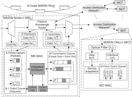
16.2.2.1 Access Traffic Aggregation.
The uplink portion of MARIN access traffic is groomed and added to the metro network without requiring intermediate queuing. In the access traffic aggregation process, the MARIN node (MN) grooms access traffic from MARIN ONUs (MOs) and aggregates it into data bursts. Each MO patches its traffic into a VOQ according to its destination in the metropolitan ring, and classes of traffic within each VOQ are preserved. The access traffic aggregation process in the MARIN architecture is agnostic to the technology of the access network. This is possible as long as the MOs can report their traffic information to the MN and allow the MN to groom their uplink traffic. In the following, EPON based optical access network is used to illustrate the operation of the access traffic aggregation process.
Due to their point-to-multi-point topology, EPON networks employ
multipoint control protocol (MPCP) to perform bandwidth assignment and polling [21].
EPON MPCP protocol relies on GATE and REPORT messages for bandwidth grant and
request. MARIN utilizes the same MPCP control in the access segment to perform
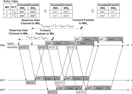
upstream traffic allocations. Figure 16.6 illustrates an example of the MARIN
MPCP protocol window for access traffic aggregation. The integrated transmission
scheduler at source MN0 sends downlink ![]() message to MO1 when there is enough data aggregated
for the destination MN1 on the ring. MO1 selects data from
VOQ1 and send its uplink data following
message to MO1 when there is enough data aggregated
for the destination MN1 on the ring. MO1 selects data from
VOQ1 and send its uplink data following ![]() message. Following the data
transmission, MO1 sends a REPORT message containing the updated
VOQ1 lengths to the MN1. In the transmission from
MN0 to MN2, the bursts suffer from additional scheduling
delay. In the example shown in Figure 16.6, this additional delay is illustrated
by the fact that the new sub-burst should wait for the completion of the previous
sub-burst. In the MARIN architecture, MOs employ colorless transmitter, which allows
them to flexibly transmit the allocated wavelength.
message. Following the data
transmission, MO1 sends a REPORT message containing the updated
VOQ1 lengths to the MN1. In the transmission from
MN0 to MN2, the bursts suffer from additional scheduling
delay. In the example shown in Figure 16.6, this additional delay is illustrated
by the fact that the new sub-burst should wait for the completion of the previous
sub-burst. In the MARIN architecture, MOs employ colorless transmitter, which allows
them to flexibly transmit the allocated wavelength.
Figure 16.6. Example of MARIN multi-threaded traffic aggregation protocol.
After upstream traffic is groomed into a burst using MPCP control, the aggregated burst is received and reassigned to a wavelength in the metro wavelength set {λm}. Because the metropolitan area resource is acquired prior to access traffic grooming is scheduled, source MNo can immediately add the burst directly to destination MNi without undergoing further queuing. As a result, the transmission queue in MN does not have to queue uplink access packets. Whereas the integrated scheduler is more complex than individual metro or access scheduler, MARIN reduces hardware complexity in the MN and delay associated with intermediate queuing.
16.2.2.2 Metropolitan Data Transport Protocol.
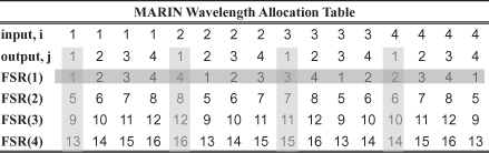
MN receiver relies on a coarse WDM (CWDM) filter to strip off consecutive bands of dense WDM wavelengths from the ring and a cyclic AWG-based passive router to forward added traffic. The allocation of the wavelength resource is determined by the dynamic switching and wavelength allocation protocol (DSAWP). Figure 16.7 illustrates the wavelength routing table used by the DSWAP [22] method. When a laser connected to input port i wants to transmit to output port k, it can transmit on a set of wavelength λJ, where J ∈ {j = (k − i + 1) + n · B|0 < j < max}. The parameter B represents the free spectral range (FSR) and wavelengths separated by B channels apart could be reused at the same fiber output. A typical AWG has FSR between 4 and 32 DWDM channels and can support up to 128 DWDM wavelengths. The index n is selected such that the wavelength index j is between 1 and 128. The set J represents all admissible wavelengths that can be sent from input laser i to output access network k. The objective of the DSWAP is to allocate a laser-wavelength (i, j) pairing when access or metro traffic demands bandwidth resource. All wavelengths are further partitioned into the sets {λa} and {λm}, which represent the wavelengths for access and metro transport. The passive router utilizes a WDM filter to separate wavelengths {λm} and inserts them into the metropolitan ring. The remaining wavelengths {λa} are unaffected and continue onto the access network.
Figure 16.7. Example of MARIN wavelength routing table (4 × 4 AWG, FSR = 4, λ = 16). In the example, the target user employs filter FSR(1) and is connected to input port 1.
In the MARIN access segment, each MO is connected to the MN through the access distribution network via one of its cyclic AWG output ports. Similar to the MN receiver, each MO receiver also employs a CWDM filter to strip off consecutive bands of DWDM wavelengths. When a downlink access packet is received from the ring, DSAWP first identifies a laser source i for the packet based on backlog in laser transmission queue. Once the laser source i with the shortest backlog is identified, the scheduler finds an appropriate AWG output port k to connect to the destination MO. After input laser i and output access network k are defined, a row is selected from the allocation table. Each column in the {λa} set of the allocation table corresponds to the stripping waveband of a MO. The final (i, j) pairing of the allocation is the intersection of the identified row and column in the table. To summarize, the allocation of (i, j) pairing for access traffic depends on the input port of the earliest available laser and the output port that connects to the MO.
In the MARIN metro network segment, the metropolitan ring is connected to all outputs of the cyclic AWG. This allows every laser to connect the ring with all the available wavelengths in the metro wavelength set {λm}. Each MN receiver is assigned to a fixed wavelength and employs a DWDM filter to strip a single wavelength for every receiver. Every MN could have more than one receiver. The MN schedules a burst to node N when it accumulates enough traffic requests for node N from the MOs. Once the burst threshold is reached, the MN schedules a downlink GATE message to the MOs and grooms uplink data into a single burst from the MOs. When the uplink burst arrives, the MN forwards the received burst to laser i and directly sends them over the allocated wavelength j.
The MARIN metro transport adapts token control to support lossless burst transport. Unlike in OBT, each wavelength token represents a free receiver in MARIN. To transmit a burst from the source MN to the destination MN without intermediate switching, the source node acquires a wavelength token λj from the ring and transmits the aggregated burst using the laser i with shortest transmission backlog. Metro traffic is given priority over the access traffic and all active or scheduled access packets for laser i are suspended during the transmission of the metropolitan traffic.
16.2.2.2 Metropolitan and Access Resource Sharing.
MARIN reuses the same light source for downlink access and metropolitan traffic. The integrated transmission scheduler arbitrates the usage of the light sources, allowing better resource utilization through the use of statistical sharing of them. To evaluate its performance against the nonintegrated architecture, simulations have been performed. In the simulation, the MARIN architecture adapts a variant of the token control protocol. The token control is adapted because it was shown to have robust performance compared with an RPR network. In MARIN, each waveband token represents a free receiver whereas in OBT a wavelength token only refers to free wavelength. This is because MARIN does not utilize receiver switching and each receiver can receive a unique set of wavelengths.
Figure 16.8 shows the performance evaluation of MARIN network. First, MARIN is compared against a metropolitan area network with fixed transceivers, such as OBT and RPR. The simulation scenario simulates a metropolitan area ring with seven nodes. Both fixed- and tunable-transmitter-based architectures employ four 2.5-Gbit/s transceivers. Each metro node further supports four access networks at 1.25-Gbit/s downlink rate (about 1 Gbit/s useful data after discounting the overhead). RPR is selected as the fixed transmitter based architecture in the simulation. The simulation results in Figure 16.8a are used to show that the tunable transmitter-based architecture is far more scalable than fixed transmitter architecture. This is because while there are only four common data channels available for the entire Fixed-Tx network, there is no limit to the number of data channels that can be used in the Tunable-Tx network. In this example, the Tunable-Tx architecture can use a total of 28 (4 × 7) wavelength channels and is able to reach any receiver using any four dedicated wavelengths without contending with another receiver node.
Figure 16.8. MARIN metro-access resource sharing performance.
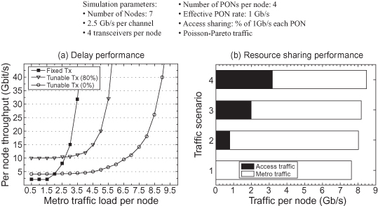
In Figure 16.8a, the transmitters in MARIN node also have to support downlink access traffic. For example, the differences in metropolitan traffic throughput between two MARIN scenarios are caused by increasing access traffic loads. To demonstrate the performance of this transmitter resource sharing property, Figure 16.8b compares the total transmitter utilization under four different downlink access traffic loads. They are 0%, 20%, 50%, and 80% loads and correspond to series 1, 2, 3, and 4, respectively. The results show the maximum metropolitan traffic that the MARIN node can support when simultaneously supporting the required access demands. Results show slight total transmitter utilization improvement. This is because MARIN enables statistical multiplexing in the access network by making all four of its transmitters available to the receivers at any given time.
16.2.2.3 WDM Scalability and RPR Upgrade.
In MARIN, if there can be a maximum of 64 wavelengths for metropolitan traffic, there can be a maximum of n nodes in the network, where n = 64/m and m represents the number of receivers per node. For the access network, since each access distribution network connects only to one output port of the AWG, each access network can support n = 64/4 = 16 terminals with unique waveband passing characteristics.
Standard RPR currently does not provide a clear guideline to upgrade from its single-channel platform into a multiple-channel one. The MARIN architecture provides a clear method to scale to multichannel platform using WDM technology. Figure 16.9a illustrates the method to upgrade MARIN from single-channel to a multiple-channel platform. The figure shows a modified MN to integrate a legacy RPR node. VOQs are added in the MN to convert excess RPR traffic into MARIN traffic. Figure 16.9b shows the performance of the network when it upgrades from a single-channel RPR into an integrated RPR-MARIN platform. The results show that the integrated RPR-MARIN network can gracefully transit excess RPR traffic without scarifying bandwidth utilization. During the transition phase, where the metropolitan traffic load first exceeds the maximum bandwidth that RPR can support, integrated MARIN-RPR traffic suffers from additional delay because MARIN cannot provide immediate channel access. However, the delay performance does not further degrade up to the full capacity of the second light source. Figure 16.9b also shows that the utilization of a second RPR would result in a lower throughput compared to the case where a MARIN architecture is used.
Figure 16.9. (a) MARIN-RPR integration. (b) MARIN-RPR integration performance.
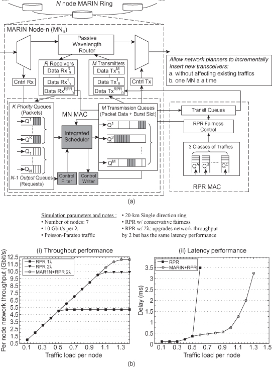
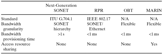
Table 16.3 presents a comparison among MARIN, OBT, RPR, and Next-Generation SONET/SDH in terms of bandwidth granularity, bandwidth provisioning time, and access resource sharing [15]. Regarding bandwidth granularity, next-generation SONET utilizes SONET hierarchy; that is, the granularity of bandwidth is a multiple of SONET virtual tributary groups, whereas RPR supports SONET and Ethernet frames. In turn, both OBT and MARIN can support flexible traffic due to their fast tunable or transmitting capability. Regarding bandwidth provisioning times, next-generation SONET is based on conventional management systems, whose setup times of connections take from seconds to some minutes, whereas RPR, OBT, and MARIN are all in the submillisecond range of connection provisioning times. The major benefit of MARIN over the other three technologies is its ability to share access resources due to its integrated architecture.
TABLE 16.3. Comparison of Next-Generation Metropolitan Area Network (MAN)
16.3 CONVERGENCE OF OPTICAL AND WIRELESS ACCESS NETWORK
The increasing convergence between optical and wireless access networks is also bringing significant changes to the design of metropolitan-access networks. This section examines the design of new metropolitan-access architectures based on optical-wireless access convergence. Specifically, a metro-access optical infrastructure for municipal WiFi mesh network is presented. The architecture employs a metropolitan backbone that relies on the aforementioned MARIN architecture. The example demonstrates an evolutionary architecture that is capable of physically scaling to support future demands and technologies. Moreover, the concept of integrated control framework is introduced to demonstrate potential performance enhancements in the municipal WiFi mesh network and as well as in other standard-based converged access networks.
16.3.1 Municipal WiFi
WiFi network is one of the most popularly used wireless technologies. Moreover, comparing to infrastructure-based technologies like WiMAX or Long-Term Evolution (LTE), WiFi requires a smaller upfront investment on installation and equipment. Because of these reasons, new municipal access networks are considering to leverage WiFi networks. In past years, a number of companies pursued aggressive plans to deploy municipal WiFi (Muni-WiFi) networks in American cities. However, until now, Muni-WMN networks have limited performance due to their inability to deliver broadband-like experience to end users across a large area.
Figure 16.10 illustrates the architecture of a common Muni-WiFi employing a wireless mesh network (WMN). In this architecture, access gateways (AGs) connect to the fiber backbone and provide the point of ingress and egress for aggregated downstream and upstream traffic, respectively. The access routers (ARs) serve as the intermediate node and relay transit traffic before they arrive to the destination. Traffic is routed from the AG to the AR or vice versa typically via a k-nearest-neighbor routing strategy. This section will first present a standard compatible metropolitan optical backbone for Muni-WiFi based on EPON technology.
Figure 16.10. Municipal WiFi mesh architecture.
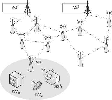
16.3.1.1 Challenges in Large-Scale WiFi Mesh Network.
WiFi-based WMN is viewed as a cost-effective solution to provide network coverage over a large area. The ARs could be deployed throughout the city without requiring significant operational or capital expenses. The operator can conveniently extend the coverage of the network by incrementally placing ARs at desirable locations. Traffic can be routed to the backbone network through the access gateways, and the network can be managed in a distributed fashion without requiring centralized planning. Whereas this approach enables rapid network deployment, the resulting network usually suffers from significant relay traffic and low spectral efficiency, leading to a reduction of its effective bandwidth. Since broadband experience would require significantly higher end-user throughput rate than currently provided rates, the throughput bottleneck in current WMN based Muni-WiFi must be addressed.
The first approach is to enhance individual wireless link capacity through the use of high-throughput wireless PHY technologies. High-throughput (HT) technology such as P802.11n multiple-input multiple-output (MIMO) draft standard can increase the maximum PHY bit rate from 54 Mbit/s in current 802.11 a/g standard to more than 300 Mbps. Currently, the IEEE P802.11ac very high throughout (VHT) task group studies advanced technologies such as multiple channels and/or spatial division multiple access (SDMA) to further increase link capacity. The VHT specification aggressively predicts more than 1-Gbit/s MAC throughput rate when a combination of multiple channels and SDMA technologies is used.
As promising as these physical layer enhancements are, they cannot sufficiently alleviate the throughput bottleneck in mesh networks for one glaring reason. An alternative approach to enhance the effective network throughput is to reduce the amount of intermediate transit traffic in the WMN. The effective throughput rate of a WMN increases when the physical hop count reduces in the network. This approach, also referred to as cell splitting in WMN, requires increasing number of AGs connecting to backbone. Figure 16.11a illustrates the cell splitting gain using a simulation study of WMN capacity with a high-fidelity simulator [23]. The simulation study emulates a square torus universe with 12 km in each side that wraps interference around the edge of the universe. ARs are placed 100 m apart and uniformly distributed in this universe. AGs are placed at the intersections of the streets to allow maximum neighbor visibility. The simulator considers effects of propagation characteristics, shadowing, and co-channel interferences to the calculation of the signal-to-interference-plus-noise ratio (SINR). The PHY layer employs 802.11 a/g technology and the physical communication rate depends on the instantaneous SINR.
Figure 16.11. Effective network throughput gain using cell splitting.
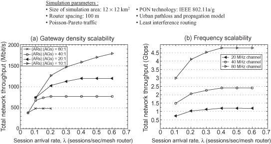
Simulation results in Figure 16.11a shows that when a single 20-MHz channel is used, an aggregate throughput of 773 Mbit/s and 1.2 Gbit/s is supported under AR : AG ratio of 40 and 20, respectively. The overall network throughput experiences a diminishing return with respect to the number of connected gateway routers. This is because the co-channel interference effect is quite high when gateways are located at nearer distances. To alleviate the bottleneck, multiple frequency bands are desired and Figure 16.11b shows the expected throughput performance using wider frequency band when limit the AR : AG ratio to 20. Thus, to optimally support the traffic demand in future metropolitan area access networks, a combination of multiple channel and spectrally efficient techniques, as well as careful placement of the ONU to increase the AR : AG density with minimum infrastructure cost, is desirable.
To support the increase of AG density, a scalable and physically extensible infrastructure must be in place. Current wireless backbone solutions primary rely on T1 or T3 circuits [24], since these lines provide bit rates of Mbit/s and are widely common. However, these fixed circuits are very costly and their infrastructure cannot be flexibly expanded due to the point-to-point characteristic of these lines. An alternative to these two problems is to employ a TDM-PON as the backbone to provide a logical point-to-point connection over a cost-effective and flexible point-to-multipoint topology. Nevertheless, a large-scale wireless network exhibits widely varying traffic demands within its subscription groups and a TDM-PON has limited reach and bandwidth flexibility beyond a fixed group of terminals. Furthermore, a TDM-PON is not expected to completely satisfy the bandwidths especially when the WMN interfaces start to evolve from current 802.11 a/g into HT or VHT standards. To address these problems, two architectures are proposed to support the backbone network of a large-scale WMN.
16.3.1.2 MARIN: Metropolitan WDM Ring Backbone.
In reference 25, an integrated metropolitan-access optical network is proposed to provide the necessary backbone network to large-scale WiFi-based WMN. This architecture, shown in Figure 16.12, employs an integrated optical backbone that relies on a WDM metropolitan ring and is considered a variant of the MARIN network. In the MARIN hybrid architecture, the EPON distribution network is mostly unchanged and remains passive. The backbone fiber ring replaces current central offices (Cos) with a passive splitter/filter to connect these distribution networks. The ring integrates existing EPON distribution networks and consolidates their OLTs into a unified CO. Wavelength resources and traffic controls are all centrally managed by the new CO. The MARIN hybrid architecture leverages existing standards and equipments to allow flexible placement of AGs at the edge of the distribution network.
Figure 16.12. (a) MARIN hybrid wireless metro-access network. (b) MARIN backhaul architecture.
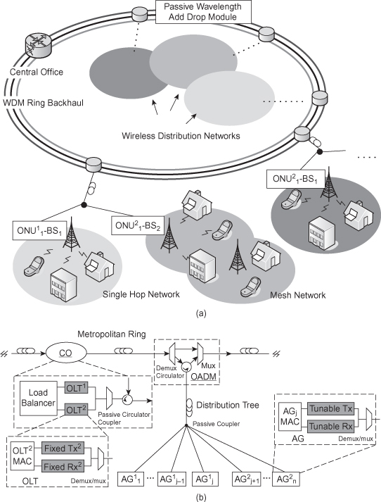
The architecture makes selected changes to existing EPON at the physical media dependent (PMD) sublayer. MARIN moves each EPON network onto a different pair of operating wavelengths instead of reusing the same pair of wavelengths. This allows MARIN to support multiple EPON networks via a single metropolitan ring backbone and a single consolidated CO. Moreover, these changes occur only in the PHY layer of the terminals and are not visible to the system. In the new CO, each OLT employs a fixed CWDM transceiver and is assigned a unique wavelength pair to connect to the subscribed AGs.
The EPON-WiFi further integrated AG employs a tunable receiver to allow flexible subscription to multiple OLTs. This allows load balancing in the backbone network when aggregated traffic overutilizes part of the wavelengths. In large local area networks, this may occur when the network load increases due to varying geographical traffic patterns. Utilizing existing EPON MPCP and auto-discovery process, the CO is able to move the AG from an overutilized wavelength to an underutilized one. An illustration of this wavelength load balance process is shown in Figure 16.13a and discussed below.
Figure 16.13. (a) Effective network throughput. (b) Backhaul wavelength load balancing performance.
The backbone wavelength load balancing process starts with
OLT1 sending a wavelength reallocation GATE message to the identified
![]() . Upon receiving the reallocation
command, the
. Upon receiving the reallocation
command, the ![]() stops its operation and
tunes its wavelength from λ1 to λ2. After a fixed waiting time
to wait for the wavelength tuning operation to complete in AG, OLT2
starts the auto-discovery process by sending a registration GATE2 message
and expects for REGISTER_REQ2 from the reallocated
stops its operation and
tunes its wavelength from λ1 to λ2. After a fixed waiting time
to wait for the wavelength tuning operation to complete in AG, OLT2
starts the auto-discovery process by sending a registration GATE2 message
and expects for REGISTER_REQ2 from the reallocated ![]() during the discovery window. Upon
successfully receiving REGISTER_REQ2 message from the
during the discovery window. Upon
successfully receiving REGISTER_REQ2 message from the ![]() , OLT2 sends a
REGISTER2 message containing the unique link layer identification
(LLID) number for the AG. The load balance operation is successfully completed when
the
, OLT2 sends a
REGISTER2 message containing the unique link layer identification
(LLID) number for the AG. The load balance operation is successfully completed when
the ![]() responds with the
REGSTER_ACK2 message to the OLT2. If the operation fails
or OLT2 cannot support the new AG, the AG moves back to the original home
wavelength for subscription and subscribes to OLT1 through its
auto-discovery process.
responds with the
REGSTER_ACK2 message to the OLT2. If the operation fails
or OLT2 cannot support the new AG, the AG moves back to the original home
wavelength for subscription and subscribes to OLT1 through its
auto-discovery process.
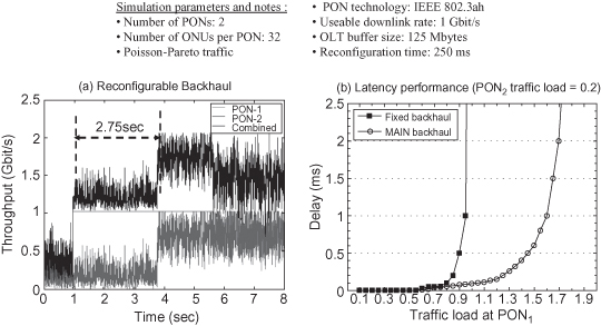
The backbone load balance operation and its protocol are demonstrated in reference 25. In the paper, the AG employs a tunable receiver based on MEMS tunable filter that reports a 33.6-µs response time. Figure 16.13a shows the simulation results based on this protocol and set the guard time to the tuning time plus the typical uplink guard time between frames. The expected reconfiguration time is found to be 250 ms on average, and the reconfiguration time is fast enough such that the OLT can hold onto the packets for the reallocated AG during its reconfiguration. In the example here, the OLT can buffer up to 125 Mbytes of data for each ONU during reconfiguration state. In the simulation, the access traffic loading for PON1 increases from 0.2 to 1.2 at t = 1.0 s. It takes 2.75 s for PON1 to notify the overloading problem (i.e., with traffic reaching buffer limit), and it takes another 250 ms to complete the reconfiguration. Figure 16.13b shows the network performance enhancement of the reconfigurable backbone architecture versus a fixed architecture, where the traffic load for one of the EPONs exceeds the maximum load for a single wavelength and the load for the other EPON remains fixed at 0.2.
16.3.1.3 Integrated WMN Control: Downlink Load Balanced Routing.
Besides dynamically allocating wavelength resources in the network, MARIN hybrid architecture introduces an integrated control plane to support dynamic wireless resource allocation. In reference 26, an integrated load balance routing algorithm is proposed with the assistance from an integrated control plane. The control plane utilizes the k-best routing scheme and routes excess traffic load via the secondary (second best) AG to reduce traffic backlog in the primary (best) AG. Current 802.11 s WMN routing employs hybrid wireless mesh protocol (HWMP), which is a hybrid of adhoc on-demand distance vector routing (AODV) and spanning-tree based routing. HWMP allows the routers to discover the most advantageous path in a distributed fashion, depending on the particular metric it employs. To achieve a high-throughput path between the source and destination, a link quality metric that reflects wireless loss rate and link bandwidth is desired. A common link quality metric is called expected transmission time (ETT), which is a bandwidth adjusted measure of the expected number of transmission (ETX) [27]. ETX estimates the expected number of transmission and re-transmission(s) and estimates the impact of interference to link quality at the MAC layer. The ETT enhances the ETX by reflecting the different transmission modes for individual links. Using an adaptation of the ETT metric, HWMP can provide good throughput and distributed routing strategy within one mesh network. However, HWMP cannot support load balancing through multiple AGs. MARIN allows such load balanced routing enhancement by dynamically assigning the packets with the same destination address (DA) to different AGs.
In the MARIN WMN, most of the traffic is infrastructure-based (i.e., routed to and from the AG), and there is little peer-to-peer traffic. When the downlink part of the WMN is overloaded, the AG will reflect the congestion through extended backlog. The MARIN integrated control can monitor the downlink congestion by examining the backlog condition reported by the AGs. MARIN modifies the REPORT message from current EPON MPCP to include the statistics for downlink queues. MARIN initially assigns the packets to the primary AG based on shortest path first (SPF) routing. Note that once the packets are routed from the OLT to AG, the AG and AR will determine the best routing path using HWMP, which is very different from SPF. However, SPF routing allows the OLT to choose a good enough approximation of the best AG for most traffic. When congestion is observed, the OLT allocates the traffic to a less loaded secondary AG according to SPF by relabeling the LLID address on the header and relieves the excess traffic load at the primary AG.
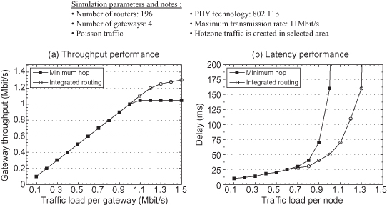
Figure 16.14 shows the simulated performance of the load-balanced WMN-EPON network versus WMN. In the simulation scenario, 196 ARs are placed over a 1400-m by 1400-m square. Four of these routers are connected to the fiber backbone. The simulation creates a traffic hotspot to one of the AG, and the performance is compared with an integrated load-balanced network against a nonintegrated network. The integrated control plane adjusts to the traffic hotspot by allocating part of the traffic to neighbor AG and can achieve 20% throughput enhancement versus the nonintegrated WMN.
Figure 16.14. Performance of MARIN integrated routing.
So far, the performance of the integrated network focuses on backbone capacity and wireless throughput enhancements. References 26 and 28 present pioneering works in this area by first integrating WiFi with an EPON network. An integrated control plane could provide many additional benefits for the OWI network. One benefit is that an integrated control plane can provide end-to-end QoS and better management. Integrated OWI control framework, in fact, is an active research area. The majority of the published works in this area studies WiMAX and EPON systems due to their similarity in terms of bandwidth and bandwidth grant/reservation mechanism. Section 16.3.2 presents the OWI integrated framework and its benefits by using WiMAX and EPON standards as the example.
16.3.2 Convergence Between EPON and WiMAX
EPON and WiMAX share a number of important properties. Most importantly, 802.16 base stations (BS) are equipped with an Ethernet interface that can be easily connected to the EPON ONU. Both networks employ similar bandwidth request/allocation and QoS supporting mechanisms. They also support similar physical bandwidth and employ the same point-to-multi-point architecture. Table 16.4 summarizes key similarities between these two networks. The convergence would further facilitate the combination of complementary characteristics of EPON and WiMAX networks.
TABLE 16.4. EPON and WiMAX Comparison
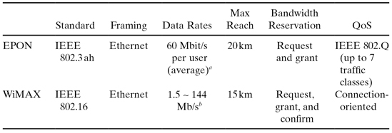
aBandwidth depends on the number of users, and the number listed here is typical values.
bAchievable data rate depends on channel conditions and is shared by multiple users.
Figure 16.15a illustrates the integrated EPON and WiMAX architecture. Under this integrated architecture, WiMAX extends the coverage area and supports mobility to subscriber stations (SS). EPON supplies a low-cost and dynamic backhaul infrastructure to the WiMAX network. This architecture saves significant CAPEX associated with the infrastructure comparing to conventional point-to-point backhauls, such as T1 leased lines.
Figure 16.15. (a) EPON-WiMAX integration architecture. (b) Control module details of EPON-WiMAX integrated network.
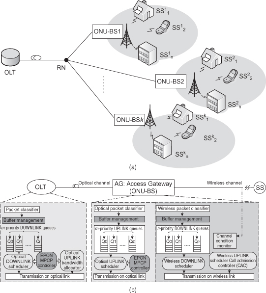
Despite the fact that they share many similarities, EPON and WiMAX use different operational protocols in their bandwidth control and QoS mechanisms. A converged interface with integrated control could further enhance the performance of the networks. The following analysis summarizes the state-of-the-art research in this area. Figure 16.15b shows the module details of the integrated system. In this illustration, the ONU and the BS are combined into a single hybrid (AG). The two devices could be independent, in which case the interworking relies on an external software bridge to exchange control and data. The highlight boxes represent key enhancement functions and they are subjects of the following discussions. The discussion will be separated into uplink and downlink enhancements.
16.3.2.1 Uplink Enhancement: End-to-end QoS, and Call Admission Control.
EPON MPCP supports dynamic bandwidth allocation (DBA) using methods such as interleaved polling with adaptive cycle time (IPACT) [29]. IPACT schedules uplink traffic in a just-in-time architecture based on reported traffic requests. IPACT and other EPON DBA are strictly queue based; that is, they make the allocation decision based on reported uplink queue lengths. Unlike EPON, the physical layer of WiMAX supports adaptive modulation and coding (AMC) to adapt to channel conditions. Thus, its bandwidth allocation process is based on the channel rate and employs variants of latency-rate (LR) schedulers [30]. In networks employing LR schedulers, end-to-end delay and buffer requirement are determined by latency and allocated rate, instead of queue length. A solution to consolidate their differences is to employ a hierarchical scheduler. Hierarchical scheduler is also better suited to in an integrated network rather than a direct scheduler because the latter cannot scale with a large aggregate number of queues.
Moreover, in order to support better end-to-end differentiated service (DiffServ), the converged interface at the AG needs to convert 802.16 differentiated traffic to appropriate EPON queues and vice versa. The IEEE 802.16 standard defines four types of scheduling services—that is, unsolicited grant service (UGS), real-time polling service (rtPS), extended real-time polling service (ertPS), non-real-time polling service (nrtPS), and best effort (BE) [31, 32]. The EPON standard supports up to eight different priority queues in the ONU and uses the IEEE 802.Q guideline to distinguish the following traffic classes: network control, voice, video, controlled load, excellent effort, best effort, and background. Yang et al. [33] demonstrate a simplified mapping using three priorities at EPON: best effort (BE), assured forwarding (AF), and expedited forwarding (EF). In the proposed scheduling algorithm, UGS traffic is mapped to EF and rtPS/ertPS traffic is mapped to AF. The scheduler employs a three-level scheduling hierarchy where local scheduling takes place inside the SS, BS, and OLT. To provide basic fairness among subscriber stations, the algorithm splits the allocated bandwidth evenly among SS that have made the corresponding class of connection requests. Under this simple scheme, the converged network is able to support coarse end-to-end DiffServ from the SS to the OLT.
Performance enhancement could also be achieved by employing call admission control (CAC) at the AG. The CAC algorithm considers end-to-end delay across WiMAX and EPON network for each connection request to guarantee QoS. Because WiMAX is connection-oriented, bandwidth requests are made for every connection. CAC helps sift through connection requests and rejects unserviceable requests, preventing them from competing network resources with serviceable packets. When a new SS connection request arrives, the CAC algorithm would accept the request based on existing queue size and expected service time, Texp. Texp depends on three parameters: queuing time, polling delay, and wireless transmission and propagation delay. The queuing time and polling delay depends on the AG queue occupancy and polling cycle time Tcycle, respectively.The second parameter could be known or estimated based on the particular MPCP control that is used. Furthermore, the wireless transmission delay is known based on the negotiated transmission mode between the SS and the AG. If the channel conditions vary and the transmission fails, the CAC will discard the transmission request and reevaluate based on new admission criterion when the re-transmission request arrives.
16.3.2.2 Downlink Scheduler: Power Control and Cell Breathing.
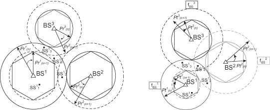
In broadband wireless access networks, the base station power is typically controlled to minimize mutual interference among adjacent cells. By lowering transmit power, a base station could further reduce coverage dynamically during heavy network load. Reducing coverage could reduce the number of subscribed users and relieve itself from excess traffic burden. Similarly, a neighboring base station could share the excess traffic load and expand its coverage. This operation is called cell breathing, and such a dynamically balanced network could provide better QoS within a single cell or statistically support more mobile users. Figure 16.16 illustrates the dynamic cell breathing concept in WiMAX network. In each of the two examples, BS1 reduces its transmission power and leaves SS2–4 outside of its coverage. SS4 is not covered by any of BB1–3 during cell breathing if frequency reuse is not allowed.
Figure 16.16. Cell breathing concept.
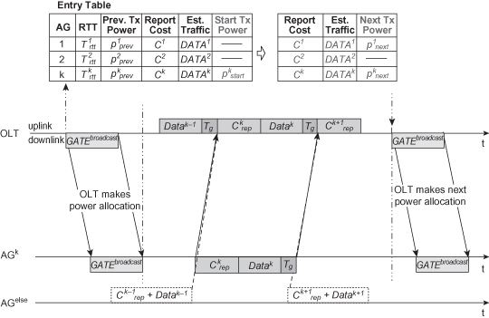
For downstream traffic, cell breathing averts extended backlog at the AG. Backlog at the AG could occur due to either overutilization or poor channel condition. To determine whether cell breathing is necessary, the OLT calculates the estimated total service time and equalizes them across all AGs. Figure 16.17 illustrates the protocol window and corresponding entry at the OLT. The computation at OLT relies on the residual backlog and control costs Ci feedback from AGiand knowing the current transmit power level Pi. In the example, Ck is determined by AGk locally based on connection queue sizes and corresponding connecting rates as well as perceived channel qualities. AGk sends Ck in an extended REPORTk message. Upon receiving the renew Ck message, the OLT determines if a further action is necessary to load-balance the network. In the example, the OLT utilizes a broadcast GATE message immediately afterward to issue power re-allocation to AG1 and AGk.
Figure 16.17. MPCP control window for cell breathing.
During cell breathing, an AG could lose connections to some subscribers and handover might occur for these subscribers. The handover problems could be effectively mitigated by using the broadcast nature of PON and queue duplicate version of the traffic at nearby handoff stations to reduce handover costs.
16.4 FUTURE OUTLOOK FOR METRO-ACCESS NETWORKS
16.4.1 100-Gbit/s Ethernet
Currently, the standardization of a next-generation 100 Gbit/s Ethernet data transport is under development in the IEEE P802.3ba 40 Gbit/s and 100 Gbit/s Ethernet Task Force [34, 35]. The transport of data traffic in metropolitan area distances through Ethernet-based equipments has been mostly motivated by the fact that the Ethernet has been very successful in LANs due to its simplicity, low cost, standardization, and compelling market penetration. The migration of the Ethernet protocol from LAN to MAN environments has been possible mainly because of the separation of the medium access control (MAC) layer from the physical (PHY) layer since the very former times of this protocol. As a result, the progress to newer Ethernet standards over different physical layer technologies and transmission media has preserved almost the same frame format of the previous standards, which have allowed the leverage of existing Ethernet installations. The choice of the 100-Gbit/s rate came naturally from the conventional evolution of the Ethernet over its previous generation—that is, a 10-fold increase in the speed over 10 Gbit/s.
Ethernet as a metro-service architecture must be able to support a large number of terminals and high-capacity links in a scalable way, as well as offer OAM capabilities and network resilience guarantees for service providers. In other words, the Ethernet as a carrier-grade platform should be able to provide almost all the benefits that the SONET/SDH networks have, but using a packet-switched platform. It is not clear yet, however, if the inclusion of all these acclaimed benefits in the Ethernet will keep its cost-effectiveness. Most of the standards activities to accomplish these goals are developed by the IEEE 802 LAN/MAN Standard Committee (LMSC) [36], who is responsible for the evolution of Ethernet in LANs and MANs. The Metro Ethernet Forum (MEF) [37], an industry consortium that aims at fostering the adoption of the Ethernet as a carrier-class platform, has been also defining Ethernet service types, management, and service level agreements (SLA) for metro and wide area environments. Parallel standardization efforts led by the ITU have mostly focused on the definition of the transport of Ethernet over TDM circuits, Ethernet protection switching, and OAM functionalities.
The 100-Gb Ethernet transmission over metropolitan networks will require very stringent component tolerances with respect to the chromatic dispersion (CD) and polarization mode dispersion (PMD) effects, since the impact of these impairments in the optical transmission increases with the square of the data rate [38, 39]. Moreover, whereas interchannel effects strongly affect mostly dispersion-compensated optical transmission systems at per-channel rate of 10 Gbaud and below, intrachannel nonlinearities (e.g. intrachannel cross-phase modulation (iXPM) and intrachannel four-wave mixing (iFWM)) severely impact such systems at per-channel rates of 10 Gbaud and above [40]. Advanced, spectrally efficient modulation formats will play a central role in the design of 100-Gbit Ethernet optical transmission systems, since an appropriate choice of the data modulation scheme can alleviate the impact of such impairments on the transmission and make a more efficient utilization of the channel spectrum at such high-speed data rates [41].
16.4.2 Future Mobile Backhaul and Fiber-Wireless Convergence
Currently, the standardization of 3G partnership project (3GPP) specifies next generation of cellular wireless networks to deliver broadband-like data rates. Besides MIMO and advanced antenna configurations, next generation cellular standards look into aggressive use of radio spectrum and advanced inter-cell interference (ICI) mitigation techniques to increase network capacity. In the former case, cellular operators have adopted the use of universal frequency reuse, that is, no frequency reuse among neighboring cells (and fractional frequency reuse at cell edge), and are considering the use of additional radio spectrum if necessary. However, with such an aggressive use of spectrum, ICI is fast becoming the limiting factor not only to the throughput performances of cell edge users but also cell throughput. ICI mitigation techniques are proposed to reduce or even avoid interferences altogether by coordinating decisions among multiple cellular sites. Therefore, they promise more efficient use of the scarce radio spectrum resource.
The performance of ICI mitigation hinges on how well the coordination is performed in the backhaul. In general, cell throughput can increase with higher degree of coordination and with greater number of coordinating cells. Recent studies have suggested the use of fiber backhaul with very high bandwidth capacity to support ICI mitigation [42, 43]. These studies employ Common Public Radio Interface (CPRI) standard, or CPRI-like digital formats, to transport radio signals over simple fiber backhaul. While these backhauls can effectively support ICI mitigation for a very small number of cells, cellular operators have very strong interests to increase both the degree and number of coordinating cells. This is because reduction of signal processing performed at the base station level can reduce the energy footprint and complexity on these remote sites. Moreover, consolidation on the number of centralized control sites can further lower the total cost of ownership (TCO) for operators.
Very recently, the Cloud Infrastructure Radio Access (C-RAN) architecture has been proposed to centralize base station processing to a super central site [44]. In particular, C-RAN proposes a very large-scale and centralized architecture to encourage centralized coordination and management. In C-RAN or other large-scale next-generation cellular architectures, advanced fiber backhaul architecture like the ones presented in this chapter are desirable over conventional ones. Reconfigurable and WDM fiber architectures such as MARIN and GROW-Net would allow the network to flexibly allocate backhaul resources to meet the dynamic needs of the wireless networks. Moreover, they enable the operators to scale their wireless network infrastructure in a graceful way. In addition, in anticipation of greater wireless broadband capacity demands, radio frequency over fiber (RoF) technologies are the focus of many active researches due in large part to their ability to substantially reduce the complexity of the remote base stations. Therefore, the combination of advanced fiber backhaul architectures and RoF technologies are expected to play a key role in the development of next generation mobile backhauls.
ACKNOWLEDGMENTS
This work has been supported in part by the U.S. National Science Foundation (NSF) under grant no. 0627085 and by the Brazilian National Council for Scientific and Technological Development (CNPq).
REFERENCES
1. R. Doverspike and P. Magill, Commercial optical networks, overlay networks and services, in Optical Fiber Telecommunications V B: Systems and Networks, I. Kaminow, T. Li, and A. E. Willner, editors, Academic Press, New York, 2008, pp. 511–560.
2. A. M. Odlyzko, Internet traffic growth: Sources and implications, in Proceeding SPIE—Optical Transmission Systems and Equipment for WDM Networking II, B. Dingel, W. Weiershausen, A. K. Dutta, and K.-I. Sato, editors, Vol. 5247, 2003, pp. 1–15.
3. ITU-T Rec. G.7041/Y.1303, Generic Framing Procedure (GFP), 2001.
4. D. Cavendish, K. Murakami, S.-H. Yun, O. Matsuda, and M. Nishihara, New transport services for next-generation SONET/SDH systems, IEEE Commun. Mag., Vol. 40, No. 5, pp. 80–87, May 2002.
5. F. Davik, M. Yilmaz, S. Gjessing, and N. Uzun, IEEE 802.17 resilient packet ring tutorial, IEEE Commun. Mag., Vol. 42, No. 3, pp. 112–118, March 2004.
6. V. Gambiroza, P. Yuan, L. Balzano, Y. Liu, S. Sheafor, and E. Knightly, Design, analysis, and implementation of DVSR: A fair high-performance protocol for packet rings, IEEE/ACM Trans. Networking, Vol. 12, No. 1, pp. 85–102, February 2004.
7. ITU-T Rec. G.709, Interfaces for the Optical Transport Network (OTN), 2001.
8. T. E. Stern, G. Ellinas, and K. Bala, Multiwavelength Optical Networks, Cambridge University Press, New York, 2008.
9. E. B. Basch, R. Egorov, S. Gringeri, and S. Elby, Architectural tradeoffs for reconfigurable dense wavelength-division multiplexing systems, J. Select. Quant. Electron., Vol. 12, No. 4, pp. 615–626, July-August 2006.
10. C. R. Giles and M. Spector, The wavelength add/drop multiplexer for lightwave communication networks, Bell Labs Tech. J., Vol. 4, No. 1, pp. 207–229, January–March 1999.
11. S. J. Ben Yoo, Optical packet and burst switching technologies for the future photonic Internet, J. Lightwave. Technol., Vol. 24, No. 12, pp. 4468–4492, December 2006.
12. K. Shrikhande, I. M. White, M. S. Rogge, F.-T. An, A. Srivatsa, E. S. Hu, S. S-H. Yam, and L. G. Kazovsky, Performance demonstration of a fast-tunable transmitter and burst-mode packet receiver for HORNET, in IEEE Optical Fiber Communication Conference (OFC 2001), Vol. 4, ThG2, San Francisco, CA, March 2001.
13. R. Chen, H. Chin, D. A. B. Miller, K. Ma, J. S. Harris, Jr, MSM-based integrated CMOS wavelength-tunable optical receiver, IEEE Photonics Technol. Let, Vol. 17, No. 6, pp. 1271–1273, June 2005.
14. M. Vrdoljak, S. I. Vrdoljak, and G. Skugor, Fixed-mobile convergence strategy: Technologies and market opportunities, IEEE Commun. Mag., Vol. 38, No. 2, pp. 116–121, February 2000.
15. J. Kim, J. Cho, S. Das, D. Gutierrez, M. Jain, C.-F. Su, R. Rabbat, T. Hamada, and L. G. Kazovsky, Optical burst transport: A technology for the WDM metro ring network, IEEE J. of Lightwave Technol., Vol. 25, No. 1, pp. 93–102, January 2007.
16. C. Elger and J. Elmirghani, A slotted MAC protocol for efficient bandwidth utilization in WDM metropolitan access ring networks, IEEE J. Selected Areas Commun., Vol. 21, No. 8, pp. 1295–1305, October 2003.
17. K. Nashimoto, PLZT waveguide devices for high speed switching and filtering, in IEEE Optical Fiber Communication Conference (OFC 2008), OThE4, San Diego, CA, March 2008.
18. S. Das , J. Kim, D. Gutierrez, L. Kazovsky, R. Rabbat, C.-F. Su, and T. Hamada, Protection and spatial reuse in Optical Burst Transport (OBT) networks, in 3rd International Conference on Broadband Communications, Networks and Systems, pp. 1–10, San Jose, CA, October 2006.
19. J. Kim, M. Maier, T. Hamada, and L. G. Kazovsky, OBT: Optical burst transport in metro area networks, IEEE Commun. Mag., Vol. 45, No. 11, pp. 44–51, November 2007.
20. S.-W. Wong, W.-T. Shaw, K. Balasubramanian, N. Cheng, and L. Kazovsky, MARIN: Demonstration of a flexible and dynamic metro-access integrated architecture, in Proceedings, IEEE GLOBECOM’07, pp. 2173–2177, Washington, DC, November 2007.
21. G. Kramer, B. Mukherjee, and G. Pesavento, IPACT: A dynamic protocol for an Ethernet PON (EPON), IEEE Commun. Mag., Vol. 40, No. 2, pp. 74–80, February 2002.
22. S.-W. Wong, W.-T. Shaw, N. Cheng, C. Qiao, L. Kazovsky, Dynamic wavelength allocation in a converged and scalable interface for metro-access ring integrated networks, in IEEE Optical Fiber Communication (OFC 2008), OTuI6, San Diego, CA, March 2008.
23. H. Lee, V. Manshadi, and D. C. Cox, High-fidelity and time-driven simulation of large wireless networks with parallel processing, IEEE Commun. Mag., Vol. 47, No. 3, pp. 158–165, March 2009.
24. P. Magill, Optical/wireless access architecture and field trials, IEEE Optical Fiber Communication Conference (OFC 2007), NThB2, Anaheim, CA, March 2007.
25. W.-T. Shaw, S.-W. Wong, N. Cheng, and L. G. Kazovsky, MARIN hybrid optical-wireless access network, in IEEE Optical Fiber Communication Conference (OFC 2007), OThM2, Anaheim, CA, March 2007.
26. W.-T. Shaw, S.-W. Wong, N. Cheng, K. Balasubramanian, X. Zhu, M. Maier, and L. G. Kazovsky, Hybrid architecture and integrated routing in a scalable optical-wireless access network, IEEE J. Lightwave Technol., Vol. 25, No. 11, pp. 3443–3451, November 2007.
27. R. Draves, J. Padhye, and B. Zill, Routing in multi-radio, multi-hop wireless mesh networks, in Proceedings, ACM MobiCom’04, pp. 114–128, Philadelphia, PA, September 2004.
28. S. Sarkar, H.-H. Yen, S. Dixit, and B. Mukherjee, Hybrid wireless-optical broadband access network (WOBAN): network planning and setup, IEEE J. Selected Areas Commun., Vol. 26, No. 6, pp. 12–21, August 2008.
29. G. Kramer, B. Mukherjee, and G. Pesavento, IPACT, a dynamic protocol for an Ethernet PON (EPON), IEEE Commun. Mag., Vol. 40, No. 2, pp. 74–80, February 2002.
30. D. Stiliadis and A. Varma, Latency-rate servers: A general model for analysis of traffic scheduling algorithms, IEEE/ACM Trans. Networking, Vol. 6, No. 5, pp. 611–624, October 1998.
31. C. Cicconetti, L. Lenzini, E. Mingozzi, and C. Eklund, Quality of service support in IEEE 802.16 network, IEEE Network, Vol. 20, No. 2, pp. 50–55, March–April 2005.
32. G. Shen, R. S. Tucker, and C.-J. Chae, Fixed mobile convergence architecture for broadband access: integration of EPON and WiMAX, IEEE Commun. Mag., Vol. 45, No. 8, pp. 44–50, August 2007.
33. K. Yang, S. Ou, K. Guild, and H.-H. Chen, Convergence of Ethernet PON and IEEE 802.16 broadband access networks and its QoS-aware dynamic bandwidth allocation scheme, IEEE J. Selected Areas Commun., Vol. 27, No. 2, pp. 101–116, February 2009.
34. IEEE P802.3ba 40 Gb/s and 100 Gb/s Ethernet Task Force: http://www.ieee802.org/3/ba/
35. J. McDonough, Moving standards to 100 GbE and beyond, IEEE Commun. Mag., Vol. 45, No. 11, pp. 6–9, November 2007.
36. IEEE 802 LAN/MAN Standards Committee: http://www.ieee802.org/index.html
37. The Metro Ethernet Forum (MEF): http://www.metroethernetforum.org/
38. C. F. Lam and W. I. Way, Optical Ethernet: Protocols, management, and 1–100 G technologies, in Optical Fiber Telecommunications V B: Systems and Networks, I. Kaminow, T. Li, and A. E. Willner, Academic Press, 2008, pp. 345–400.
39. M. Duelk and M. Zirngibl, 100 Gigabit Ethernet—Applications, features, challenges, in Proceedings, INFOCOM’06, Barcelona, Spain, pp. 1–5.
40. R.-J. Essiambre, G. Raybon, and B. Mikkelsen, Pseudo-linear transmission of high-speed TDM signals: 40 and 160 Gb/s, in Optical Fiber Telecommunications IV, I. Kaminow and T. Li, editors, Academic Press, New York, 2002, pp. 232–304.
41. P. J. Winzer and R.-J. Essiambre, Advanced optical modulation formats, Proc. IEEE, Vol. 94, No. 5, pp. 952–985, May 2006.
42. V. Jungnickel, L. Thiele, T. Wirth, T. Haustein, S. Schiffermüller, A. Forck, S. Wahls, S. Jaeckel, S. Schubert, C. Juchems, F. Luhn, R. Zavrtak, H. Droste, G. Kadel, W. Kreher, J. Mueller, W. Stoermer, and G. Wannemacher, Coordinated multipoint trials in the downlink, in GLOBECOM Workshop, pp. 1–9, Honolulu, HI, November 2009.
43. C. Hoymann, L. Falconetti, and R. Gupta, Distributed uplink signal processing of cooperating base stations based on IQ sample exchange, in Proceedings, IEEE ICC’09, pp. 1–5, Dresden, Germany, June 2009.
44. China Mobile Research Institute, C-RAN: The Road Toward Green RAN. White paper, April 2010.