14
Data Center Telecommunications Cabling
Alexander Jew
J&M Consultants, Inc., San Francisco, CA, USA
14.1 Why Use Data Center Telecommunications Cabling Standards?
When mainframe and minicomputer systems were the primary computing systems, data centers used proprietary cabling that was typically installed directly between equipment. See Figure 14.1 for an example of a computer room with unstructured nonstandard cabling designed primarily for mainframe computing.
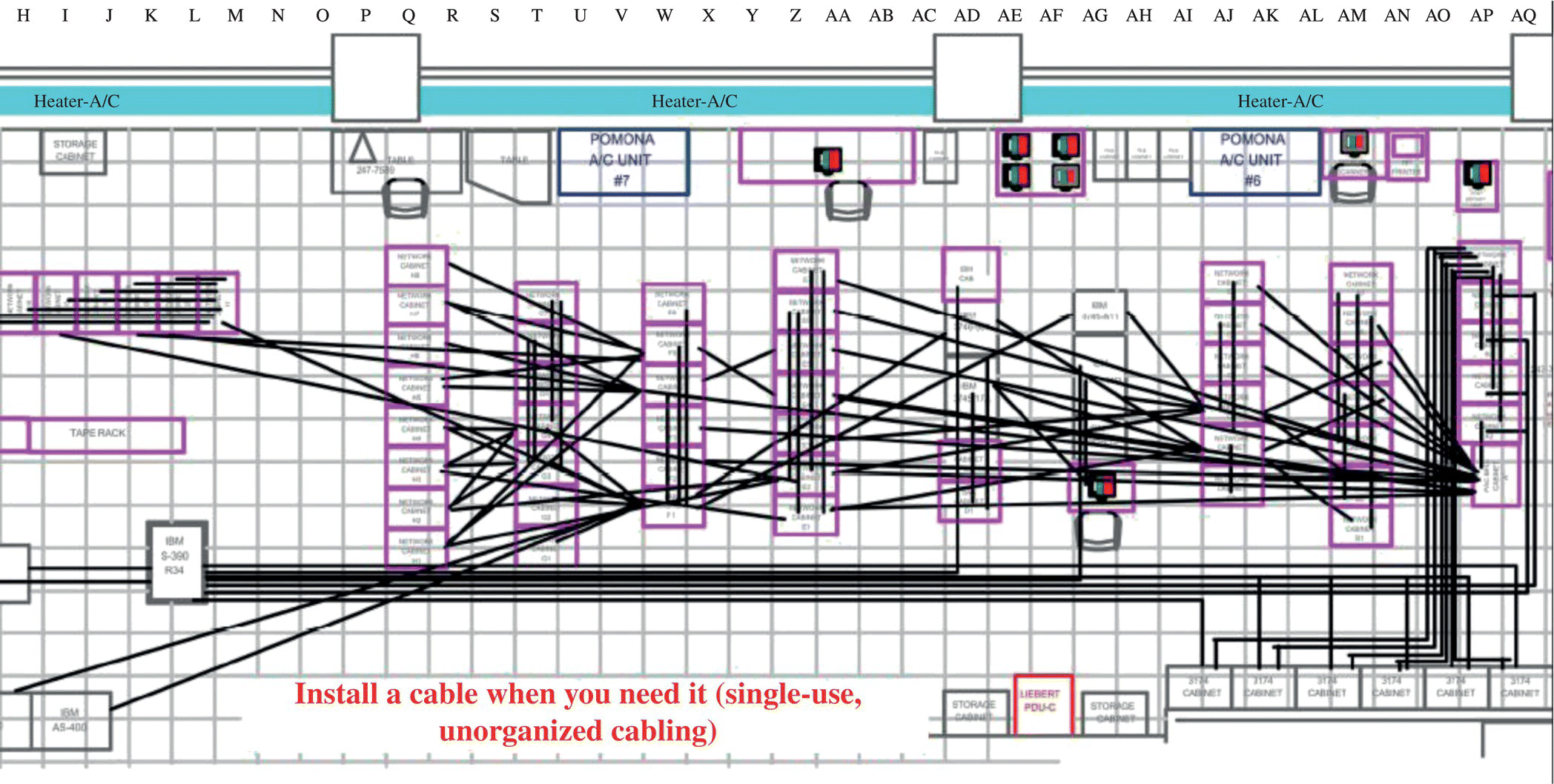
Figure 14.1 Example of computer room with unstructured nonstandard cabling.
With unstructured cabling built around nonstandard cables, cables are installed directly between the two pieces of equipment that need to be connected. Once the equipment is replaced, the cable is no longer useful and should be removed. Although removal of abandoned cables is a code requirement, it is common to find abandoned cables in computer rooms.
As can be seen in the figure, the cabling system is disorganized. Because of this lack of organization and the wide variety of nonstandard cable types, such cabling is typically difficult to troubleshoot and maintain.
Figure 14.2 is an example of the same computer room redesigned using structured standards-based cabling.
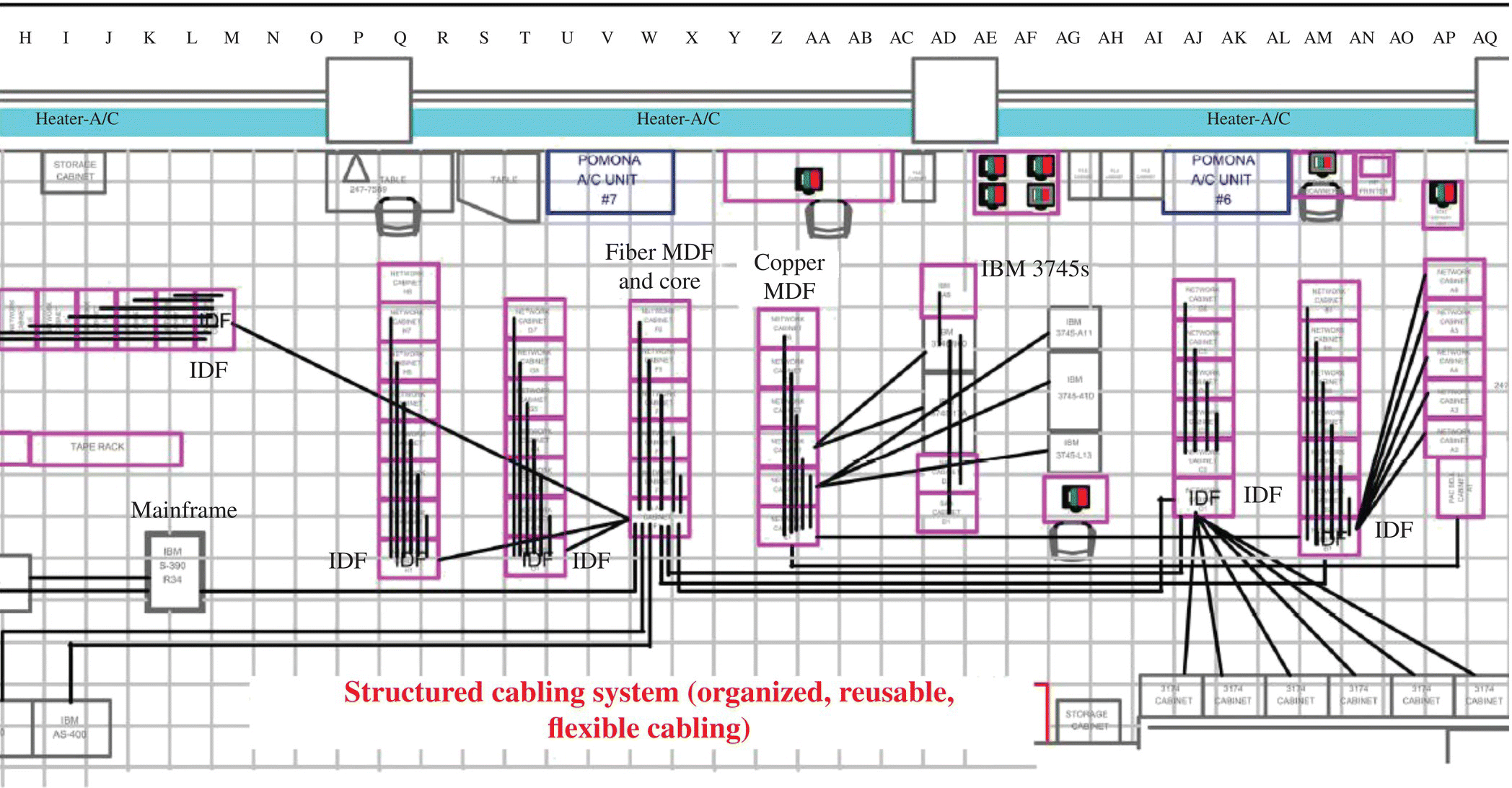
Figure 14.2 Example of computer room with structured standards-based cabling.
Structured standards-based cabling saves money:
- Standards-based cabling is available from multiple sources rather than a single vendor.
- Standards-based cabling can be used to support multiple applications (e.g., local area network (LAN), storage area network (SAN), console, wide area network (WAN) circuits), so the cabling can be left in place and reused rather than removed and replaced.
- Standards-based cabling provides an upgrade path to higher-speed protocols because they are developed in conjunction with committees that develop LAN and SAN protocols.
- Structured cabling is organized so it is easier to administer and manage.
Structured standards-based cabling improves availability:
- Standards-based cabling is organized so tracing connections is simpler.
- Standards-based cabling is easier to troubleshoot than nonstandard cabling.
Since structured cabling can be preinstalled in every cabinet and rack to support most common equipment configurations, new systems can be deployed quickly.
Structured cabling is also very easy to use and expand. Because of its modular design, it is easy to add redundancy by (copying) the design of a horizontal distribution area (HDA) or a backbone cable. Using structured cabling breaks the entire cabling system into smaller pieces, which makes it easier to manage, compared to having all cables in one big group.
Adoption of the standards is voluntary, but the use of standards greatly simplifies the design process, ensures compatibility with application standards, and may address unforeseen complications.
During the planning stages of a data center, the owner will want to consult architects and engineers in order to develop a functional facility. During this process, it is easy to become confused and perhaps overlook some crucial aspect of data center construction, leading to unexpected expenses or downtime. The data center standards try to avoid this outcome by informing the reader. If a data center owner understands their options, they can participate during the designing process more effectively and can understand the limitations of their final design. The standards explain the basic design requirements of a data center, allowing the reader to better understand how the designing process can affect security, cable density, and manageability. This will allow those involved with a design to better communicate the needs of the facility and participate in the completion of the project.
Common services that are typically carried using structured cabling include LAN, storage area network (SAN), WAN, system console connections, out-of-band management connections, voice, fax, modems, video, wireless access points, security cameras, and other building signaling systems (fire, security, power controls/monitoring, HVAC controls/monitoring, etc.). There are even systems that permit LED lighting to be provisioned using structured cabling.
14.2 Telecommunications Cabling Standards Organizations
Telecommunications cabling infrastructure standards are developed by several organizations. In the United States and Canada, the primary organization responsible for telecommunications cabling standards is the Telecommunications Industry Association, or TIA. The TIA develops information and communications technology standards and is accredited by the American National Standards Institute and the Canadian Standards Association to develop telecommunications standards.
In the European Union, telecommunications cabling standards are developed by the European Committee for Electrotechnical Standardization (CENELEC). Many countries adopt the international telecommunications cabling standards developed jointly by the International Organization for Standardization (ISO) and the International Electrotechnical Commission (IEC).
These standards are consensus based and are developed by manufacturers, designers, and users. These standards are typically reviewed every 5 years, during which they are updated, reaffirmed, or withdrawn according to submissions by contributors. Standards organizations often publish addenda to provide new content or updates prior to publication of a complete revision to a standard.
14.3 Data Center Telecommunications Cabling Infrastructure Standards
Data center telecommunications cabling infrastructure standards by the TIA, CENELEC, and ISO/IEC cover the following subjects:
- Types of cabling permitted
- Cable and connecting hardware specifications
- Cable lengths
- Cabling system topologies
- Cabinet and rack specifications and placement
- Telecommunications space design requirements
- Telecommunications pathways (e.g., conduits and cable trays)
- Testing of installed cabling
- Telecommunications cabling system administration and labeling
The TIA data center standard is ANSI/TIA-942-A, Telecommunications Infrastructure Standard for Data Centers. The ANSI/TIA-942-A standard is the first revision of the ANSI/TIA-942 standard. This standard provides guidelines for the design and installation of a data center, including the facility’s layout, cabling system, and supporting equipment. It also provides guidance regarding energy efficiency and provides a table with design guidelines for four levels of data center reliability.
ANSI/TIA-942-A references other TIA standards for content that is common with other telecommunications cabling standards. See Figure 14.3 for the organization of the TIA telecommunications cabling standards.
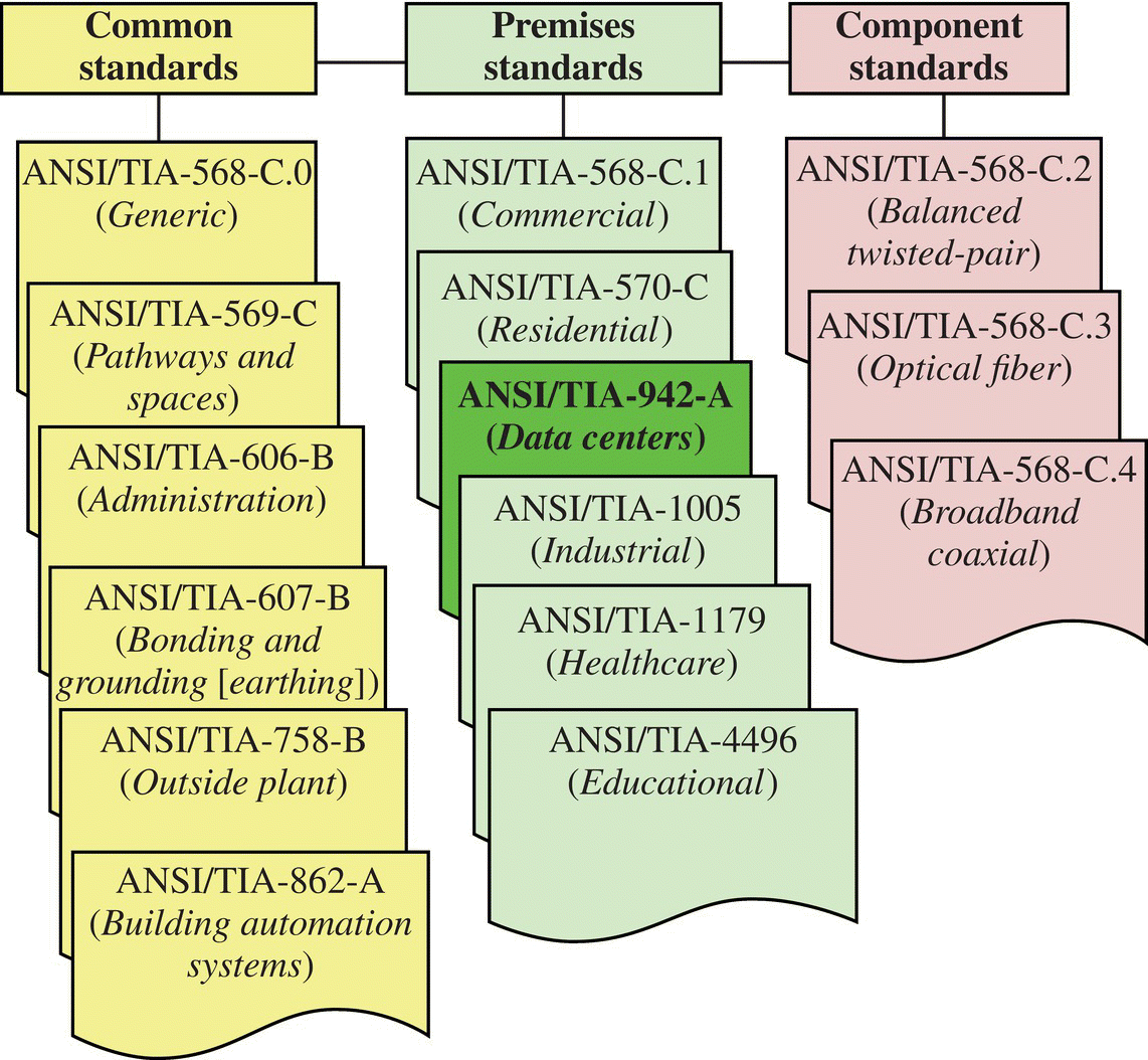
Figure 14.3 Organization of TIA telecommunications cabling standards.
Thus, ANSI/TIA-942-A references each of the common standards:
- ANSI/TIA-568-C.0 for generic cabling requirements including cable installation and testing
- ANSI/TIA-569-C regarding pathways, spaces, cabinets, and racks
- ANSI/TIA-606-B regarding administration and labeling
- ANSI/TIA-607-B regarding bonding and grounding
- ANSI/TIA-758-B regarding campus/outside cabling and pathways
- ANSI/TIA-862-A regarding cabling for building automation systems including IP cameras, security systems, and monitoring systems for the data center electrical and mechanical infrastructure
Detailed specifications for the cabling are specified in the component standards ANSI/TIA-568-C.2, ANSI/TIA-568-C.3, and ANSI/TIA-568-C.4, but these standards are meant primarily for manufacturers. So the data center telecommunications cabling infrastructure designer in the United States or Canada should obtain ANSI/TIA-942-A and the common standards ANSI/TIA-568-C.0, ANSI/TIA-569-C, ANSI/TIA-606-B, ANSI/TIA-607-B, ANSI/TIA-758-B, and ANSI/TIA-862-A.
The CENELEC telecommunications standards for the European Union also have a set of common standards that apply to all types of premises and separate premises cabling standards for different types of buildings (Fig. 14.4).
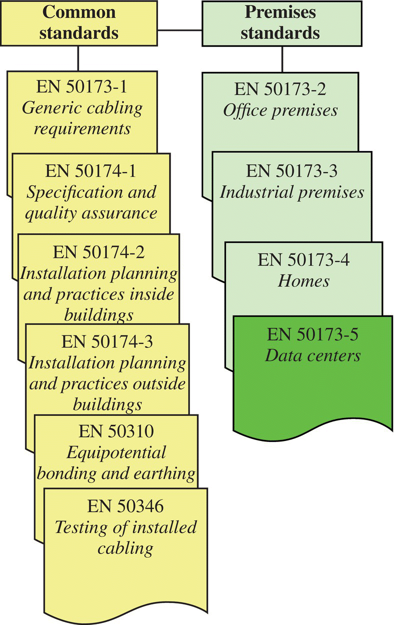
Figure 14.4 Organization of CENELEC telecommunications cabling standards.
A designer that intends to design telecommunications cabling for a data center in the European Union would need to obtain the CENELEC premises-specific standard for data centers—CENELEC EN 50173-5—and the common standards CENELEC EN 50173-1, EN 50174-1, EN 50174-2, EN 50174-3, EN 50310, and EN 50346.
See Figure 14.5 for the organization of the ISO/IEC telecommunications cabling standards.
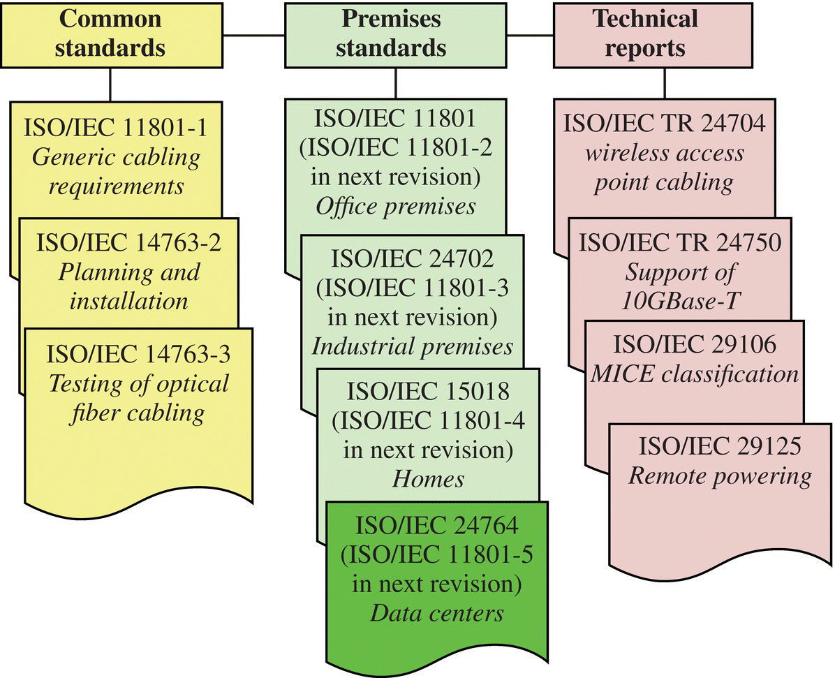
Figure 14.5 Organization of ISO/IEC telecommunications cabling standards.
A designer that intends to design telecommunications cabling for a data center using the ISO/IEC standards would need to obtain the ISO/IEC premises–specific standard for data centers—ISO/IEC 24764—and the common standards ISO/IEC 11801-1, ISO/IEC 14763-2, and ISO/IEC 14763-3. The ISO/IEC premises-specific standards will be renumbered in the next revision to correspond more closely to the scheme used in the CENELEC cabling standards. ISO/IEC 24764 will be renamed ISO/IEC 11801-5 in the next revision.
The data center telecommunications cabling standards use the same topology for telecommunications cabling infrastructure but use different terminology. This handbook uses the terminology used in ANSI/TIA-942-A. See Table 14.1 for a cross-reference between the TIA, ISO, and CENELEC terminology.
Table 14.1 Cross-reference of TIA, ISO/IEC, and CENELEC terminology
| ANSI/TIA-942-A | ISO/IEC 24764 | CENELEC EN 50173-5 |
| Telecommunications distributors | ||
| Telecommunications entrance room (TER) | Not defined | Not defined |
| Main distribution area (MDA) | Not defined | Not defined |
| Intermediate distribution area (IDA) | Not defined | Not defined |
| Horizontal distribution area (HDA) | Not defined | Not defined |
| Zone distribution area (ZDA) | Not defined | Not defined |
| Equipment distribution area (EDA) | Not defined | Not defined |
| Cross-connects and distributors | ||
| External network interface (ENI) in TER | ENI | ENI |
| Main cross-connect (MC) in the MDA | Main distributor (MD) | MD |
| Intermediate cross-connect (IC) in the IDA | Intermediate distributor (ID) | ID |
| Horizontal cross-connect (HC) in the HDA | Zone distributor (ZD) | ZD |
| Zone outlet or consolidation point in the ZDA | Local distribution point (LDP) | LDP |
| Equipment outlet (EO) in the EDA | EO | EO |
| Cabling subsystems | ||
| Backbone cabling (from TER to MDAs, IDAs, and HDAs) | Network access cabling subsystems | Network access cabling subsystems |
| Backbone cabling (from MDA to IDAs and HDAs) | Main distribution cabling subsystems | Main distribution cabling subsystems |
| Backbone cabling (from IDAs to HDAs) | Intermediate distribution cabling subsystem | Intermediate distribution cabling subsystem |
| Horizontal cabling | Zone distribution cabling subsystem | Zone distribution cabling subsystem |
ANSI/BICSI-002 Data Center Design and Implementation Best Practices Standard is another useful reference. It is an international standard meant to supplement the telecommunications cabling standard that applies in your country—ANSI/TIA-942-A, CENELEC EN 50173-5, ISO/IEC 24764, or other—and provides best practices beyond the minimum requirements specified in these other data center telecommunications cabling standards.
14.4 Telecommunications Spaces and Requirements
14.4.1 General Requirements
A computer room is an environmentally controlled room that serves the sole purpose of supporting equipment and cabling directly related to the computer and networking systems. The data center includes the computer room and all related support spaces dedicated to supporting the computer room such as the operation center, electrical rooms, mechanical rooms, staging area, and storage rooms.
The floor layout of the computer room should be consistent with the equipment requirements and the facility providers’ requirements, including floor loading, service clearance, airflow, mounting, power, and equipment connectivity length requirements. Computer rooms should be located away from building components that would restrict future room expansion, such as elevators, exterior walls, building core, or immovable walls. They should also not have windows or skylights, as they allow light and heat into the computer room, making air conditioners work more and use more energy.
The rooms should be built with security doors that allow only authorized personnel to enter. It is also just as important that keys or pass codes to access the computer rooms are only accessible to authorized personnel. Preferably, the access control system should provide an audit trail.
The ceiling should be at least 2.6 m (8.5 ft) tall to accommodate cabinets up to 2.13 m (7 ft) tall. If taller cabinets are to be used, the ceiling height should be adjusted accordingly. There should also be a minimum clearance of 460 mm (18 in.) between the top of cabinets and sprinklers to allow them to function effectively.
Floors within the computer room should be able to withstand at least 7.2 kPa (150 lb/ft2), but 12 kPa (250 lb/ft2) is recommended. Ceilings should also have a minimum hanging capacity, so that loads may be suspended from them. The minimum hanging capacity should be at least 1.2 kPa (25 lb/ft2), and a capacity of 2.4 kPa (50 lb/ft2) is recommended.
The computer room needs to be climate controlled to minimize damage and maximize the life of computer parts. The room should have some protection from environmental contaminants like dust. Some common methods are to use vapor barriers, positive room pressure, or absolute filtration. Computer rooms do not need a dedicated HVAC system if it can be covered by the building’s and has an automatic damper; however, having a dedicated HVAC system will improve reliability and is preferable if the building’s might not be on continuously. If a computer room does have a dedicated HVAC system, it should be supported by the building’s backup generator or batteries, if available.
A computer room should have its own separate power supply circuits with its own electrical panel. It should have duplex convenience outlets, for noncomputer use (e.g., cleaning equipment, power tools, and fans). The convenience outlets should be located every 3.65 m (12 ft) unless specified otherwise by local ordinances. These should be wired on separate power distribution units/panels from those used by the computers and should be reachable by a 4.5 m (15 ft) cord. If available, the outlets should be connected to a standby generator, but the generator must be rated for electronic loads or be “computer grade.”
All computer room environments including the telecommunications spaces should be compatible with M1I1C1E1 environmental classifications per ANSI/TIA-568-C.0. MICE classifications specify environmental requirements as M, mechanical; I, ingress; C, climatic; and E, electromagnetic. Mechanical specifications include conditions such as vibration, bumping, impact, and crush. Ingress specifications include conditions such as particulates and water immersion. Climatic specifications include temperature, humidity, liquid contaminants, and gaseous contaminants. Electromagnetic specifications include electrostatic discharge (ESD), radio-frequency emissions, magnetic fields, and surge. The CENELEC and ISO/IEC standards also have their own similar MICE specifications.
Temperature and humidity for computer room spaces should follow current ASHRAE TC 9.9 and manufacturer equipment guidelines.
The telecommunications spaces such as the main distribution area (MDA), intermediate distribution area (IDA), and HDA could be separate rooms within the data center but are more often a set of cabinets and racks within the computer room space.
14.4.2 Telecommunications Entrance Room
The telecommunications entrance room (TER) or entrance room refers to the location where telecommunications cabling enters the building and not the location where people enter the building. This is typically the demarcation point—the location where telecommunications access providers hand off circuits to customers. The TER is also the location where the owner’s outside plant cable (such as campus cabling) terminates inside the building.
The TER houses entrance pathways, protector blocks for twisted-pair entrance cables, termination equipment for access provider cables, access provider equipment, and termination equipment for cabling to the computer room.
The interface between the data center structured cabling system and external cabling is called the external network interface (ENI).
The telecommunications access provider’s equipment is housed in this room, so the provider’s technicians will need access. Because of this, it is not recommended to put the entrance room inside a computer room and that it is housed within a separate room, such that access to it does not compromise the security of any other room requiring clearance.
The room’s location should also be determined so that the entire circuit length from the demarcation point does not exceed the maximum specified length. If the data center is very large:
- The TER may need to be located in the computer room space.
- The data center may need multiple entrance rooms.
The location of the TER should also not interrupt air flow, piping, or cabling under floor.
The TER should be adequately bonded and grounded (for primary protectors, secondary protectors, equipment, cabinets, racks, metallic pathways, and metallic components of entrance cables).
The cable pathway system should be the same type as the one used in the computer room. Thus, if the computer room uses overhead cable tray, the TER should use overhead cable tray as well.
There may be more than one entrance room for large data centers, additional redundancy, or dedicated service feeds. If the computer rooms have redundant power and cooling, TER power and cooling should be redundant to the same degree.
There should be a means of removing water from the entrance room if there is a risk. Water pipes should also not run above equipment.
14.4.3 MDA
The MDA is the location of the main cross-connect (MC), the central point of distribution for the structured cabling system. Equipment such as core routers and switches may be located here. The MDA may also contain a horizontal cross-connect (HC) to support horizontal cabling for nearby cabinets. If there is no dedicated entrance room, the MDA may also function as the TER. In a small data center, the MDA may be the only telecommunications space in the data center.
The location of the MDA should be chosen such that the cable lengths do not exceed the maximum length restrictions.
If the computer room is used by more than one organization, the MDA should be in a separate secured space (e.g., a secured room, cage, or locked cabinets). If it has its own room, it may have its own dedicated HVAC system and power panels connected to backup power sources.
There may be more than one MDA for redundancy.
Main distribution frame (MDF) is a common industry term for the MDA.
14.4.4 IDA
The IDA is the location of an intermediate cross-connect (IC)—an optional intermediate-level distribution point within the structured cabling system. The IDA is not vital and may be absent in data centers that do not require three levels of distributors.
If the computer room is used by multiple organizations, it should be located in a separate secure space—for example, a secured room, cage, or locked cabinets.
The IDA should be located centrally to the area that it serves to avoid exceeding the maximum cable length restrictions.
This space also typically houses switches (LAN, SAN, management, console).
The IDA may contain an HC to support horizontal cabling to cabinets near the IDA.
14.4.5 HDA
The HDA is a space that contains an HC, the termination point for horizontal cabling to the equipment cabinets and racks (equipment distribution areas (EDAs)). This space typically also houses switches (LAN, SAN, management, console).
If the computer room is used by multiple organizations, it should be located in a separate secure space—for example, a secured room, cage, or locked cabinets
There should be a minimum of one HC per floor, which may be in an HDA, IDA, or MDA.
The HDA should be located to avoid exceeding the maximum backbone length from the MDA or IDA for the medium of choice. If it is located in its own room, it is possible for it to have its own dedicated HVAC or electrical panels.
To provide redundancy, equipment cabinets and racks may have horizontal cabling to two different HDAs.
Intermediate distribution frame (IDF) is a common industry term for the HDA.
14.4.6 Zone Distribution Area
The zone distribution area (ZDA) is the location of either a consolidation point or equipment outlets (EOs). A consolidation point is an intermediate administration point for horizontal cabling. Each ZDA should be limited to 288 coaxial cable or balanced twisted-pair cable connections to avoid cable congestion. The two ways that a ZDA can be deployed—as a consolidation point or as a multiple outlet assembly—are illustrated in Figure 14.6.
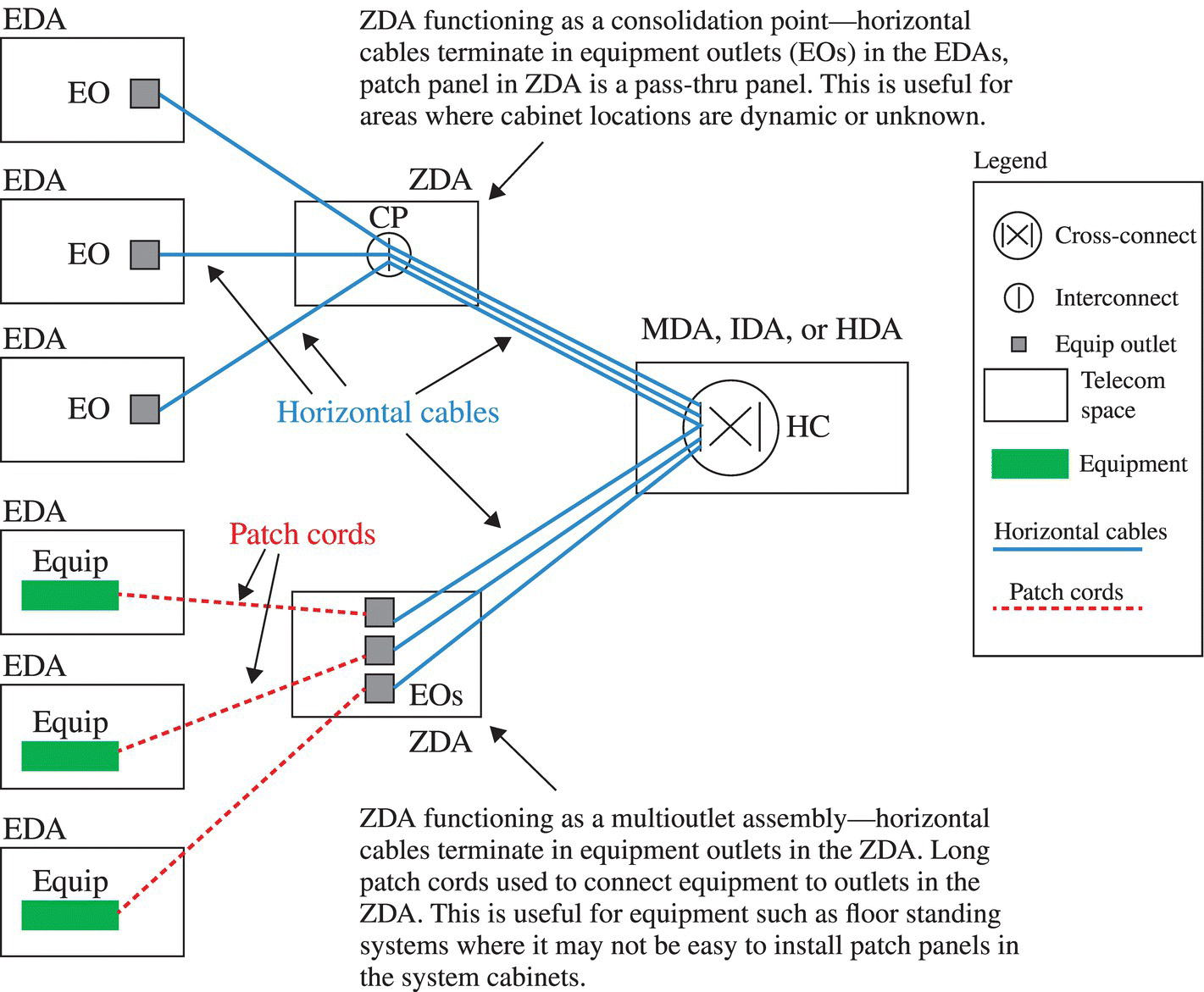
Figure 14.6 Two examples of ZDAs.
The ZDA shall contain no active equipment, nor should it be a cross-connect (i.e., have separate patch panels for cables from the HDAs and EDAs).
ZDAs may be located in underfloor enclosures, overhead enclosures, cabinets, or racks.
14.4.7 EDA
The EDA is the location of end equipment, which comprises the computer systems, communications equipment, and their racks and cabinets. Here, the horizontal cables are terminated in EOs. Typically, an EDA has multiple EOs for terminating multiple horizontal cables. These EOs are typically located in patch panels located at the rear of the cabinet or rack (where the connections for the servers are usually located).
Point-to-point cabling (i.e., direct cabling between equipment) may be used between equipment located in EDAs. Point-to-point cabling should be limited to 10 m (33 ft) in length and should be within a row of cabinets or racks. Permanent labels should be used on either end of each cable.
14.4.8 Telecommunications Room
The telecommunications room (TR) is an area that supports cabling to areas outside of the computer room, such as operations staff support offices, security office, operation center, electrical room, mechanical room, or staging area. They are usually located outside of the computer room but may be combined with an MDA, IDA, or HDA.
14.4.9 Support Area Cabling
Cabling for support areas of the data center outside the computer room is typically supported from one or more dedicated TRs to improve security. This allows technicians working on telecommunications cabling, servers, or network hardware for these spaces to remain outside the computer room.
Operation rooms and security rooms typically require more cables than other work areas. Electrical rooms, mechanical rooms, storage rooms, equipment staging rooms, and loading docks should have at least one wall-mounted phone in each room for communication within the facility. Electrical and mechanical rooms need at least one data connection for management system access and may need more connections for equipment monitoring.
14.5 Structured Cabling Topology
The structured cabling system topology described in data center telecommunications cabling standards is a hierarchical star (Fig. 14.7).
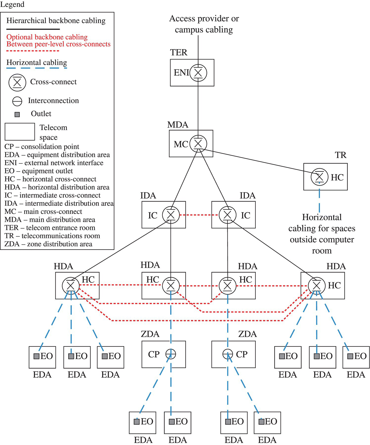
Figure 14.7 Hierarchical star topology.
The horizontal cabling is the cabling from the HCs to the EDAs and ZDAs. This is the cabling that supports end equipment such as servers.
The backbone cabling is the cabling between the distributors where cross-connects are located—TERs, TRs, MDAs, IDAs, and HDAs.
Cross-connects are patch panels that allow cables to be connected to each other using patch cords. For example, the HC allows backbone cables to be patched to horizontal cables. An interconnect, such as a consolidation point in a ZDA, connects two cables directly through the patch panel. See Figure 14.8 for examples of cross-connects and interconnects used in data centers.
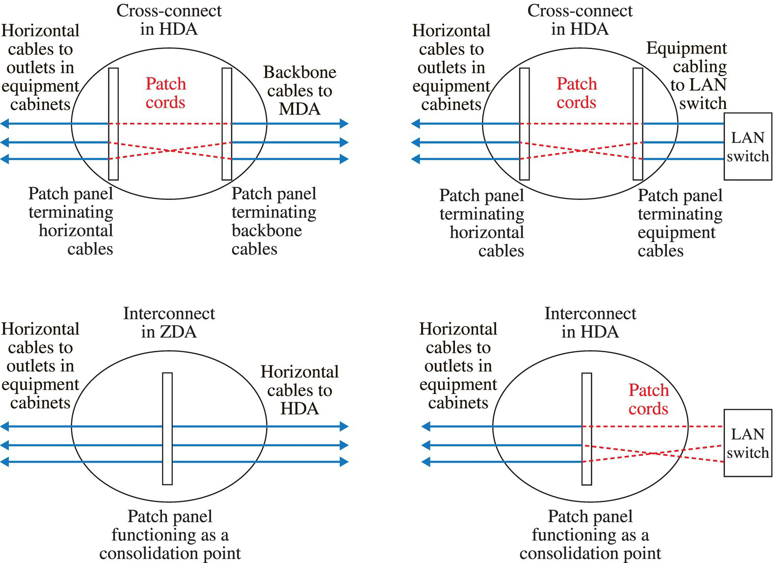
Figure 14.8 Cross-connects and interconnect examples.
Note that switches can be patched to horizontal cabling using either a cross-connect or interconnect scheme (see the two diagrams on the right side of Fig. 14.8). The interconnect scheme avoids another patch panel; however, the cross-connect scheme may allow more compact cross-connects since the switches don’t need to be located in or adjacent to the cabinets containing the HCs.
Most of the components of the hierarchical star topology are optional. However, each cross-connect must have backbone cabling to a higher-level cross-connect:
- ENIs must have backbone cabling to an MC. They may also have backbone cabling to an IC or HC as required to ensure that WAN circuit lengths are not exceeded.
- HCs in TRs located in a data center must have backbone cabling to an MC and may optionally have backbone cabling to other distributors (ICs, HCs).
- ICs must have backbone cabling to an MC and one or more HCs. They may optionally have backbone cabling to an ENI or IC either for redundancy or to ensure that maximum cable lengths are not exceeded.
- HCs in an HDA must have backbone cabling to an MC or IC. They may optionally have backbone cabling to an HC, ENI, or IC either for redundancy or to ensure that maximum cable lengths are not exceeded.
- Because ZDAs only support horizontal cabling, they may only have cabling to an HDA and EDA.
Cross-connects such as the MC, IC, and HC should not be confused with the telecommunications spaces in which they are located, that is, the MDA, IDA, and HDA. The cross-connects are components of the structured cabling system and typically comprise patch panels. The spaces are dedicated rooms or more commonly dedicated cabinets, racks, or cages within the computer room.
EDAs and ZDAs may have cabling to different HCs to provide redundancy. Similarly, HCs, ICs, and ENIs may have redundant backbone cabling. The redundant backbone cabling may be to different spaces (for maximum redundancy) or between the same to spaces on both ends but follow different routes. See Figure 14.9 for degrees of redundancy in the structured cabling topology at various levels as defined in ANSI/TIA-942-A.
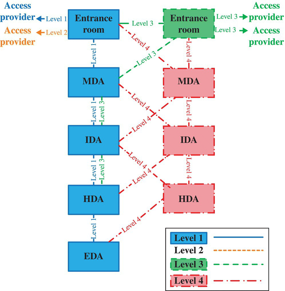
Figure 14.9 Structured cabling redundancy at various levels.
A level 1 cabling infrastructure has no redundancy.
A level 2 cabling infrastructure requires redundant access provider (telecommunications carrier) routes into the data center. The two redundant routes must go to different carrier central offices and be separated from each other along their entire route by at least 20 m (66 ft).
A level 3 cabling infrastructure has redundant TERs. The data center must be served by two different access providers (carriers). The redundant routes that the circuits take from the two different carrier central offices to the data center must be separated by at least 20 m (66 ft).
A level 3 data center also requires redundant backbone cabling. The backbone cabling between any two cross-connects must use at least two separate cables, preferably following different routes within the data center.
A level 4 data center adds redundant MDAs, IDAs, and HDAs. Equipment cabinets and racks (EDAs) must have horizontal cabling to two different HDAs. HDAs must have redundant backbone cabling to two different IDAs (if present) or MDAs. Each entrance room must have backbone cabling to two different MDAs.
14.6 Cable Types and Maximum Cable Lengths
There are several types of cables one can use for telecommunications cabling in data centers. Each has different characteristics, and they are chosen to suit the various conditions to which they are subject. Some cables are more flexible than others. The size of the cable can affect its flexibility as well as its shield. A specific type of cable may be chosen because of space constraints or required load or because of bandwidth or channel capacity. Equipment vendors may also recommend cable for use with their equipment.
14.6.1 Coaxial Cabling
Coaxial cables are composed of a center conductor, surrounded by an insulator, surrounded by a metallic shield, and covered in a jacket. The most common types of coaxial cable used in data centers are the 75 ohm 734- and 735-type cables used to carry E-1, T-3, and E-3 wide area circuits; see Telcordia Technologies GR-139-CORE regarding specifications for 734-and 735-type cables and ANSI/ATIS-0600404.2002 for specifications regarding 75 ohm coaxial connectors.
Circuit lengths are longer for the thicker, less flexible 734 cable. These maximum cable lengths are decreased by intermediate connectors and DSX panels—see ANSI/TIA-942-A.
Broadband coaxial cable is also sometimes used in data centers to distribute television signals. The specifications of the broadband coaxial cables (Series 6 and Series 11) and connectors (F-type) are specified in ANSI/TIA-568-C.4.
14.6.2 Balanced Twisted-Pair Cabling
The 100 ohm balanced twisted-pair cable is a type of cable that uses multiple pairs of copper conductors. Each pair of conductors is twisted together to protect the cables from electromagnetic interference.
- Unshielded twisted-pair (UTP) cables have no shield.
- The cable may have an overall cable screen made of either foil or braided shield or both.
- Each twisted pair may also have a foil shield.
Balanced twisted-pair cables come in different categories or classes based on the performance specifications of the cables (Table 14.2).
Table 14.2 Balanced twisted-pair categories
| TIA categories | ISO/IEC and CENELEC classes/categories | Max frequency (MHz) | Common application |
| Category 3 | N/A | 16 | Voice, wide area network circuits, serial console, 10 Mbps Ethernet |
| Category 5e | Class D/Category 5 | 100 | Same as Category 3 + 100 Mbps and 1 Gbps Ethernet |
| Category 6 | Class E/Category 6 | 250 | Same as Category 5e |
| Augmented category 6 (cat 6A) | Class EA/Category 6A | 500 | Same as Category 5e + 10G Ethernet |
| N/A | Class F/Category 7 | 600 | Same as Category 6A |
| N/A | Class FA/Category 7A | 1000 | Same as Category 6A |
ISO/IEC and CENELEC categories refer to components such as cables and connectors. Classes refer to channels comprising installed cabling including cables and connectors.
Note that the TIA does not currently specify cabling categories above Category 6A. However, higher-performance Category 7/Class F and Category 7A/Class FA are specified in ISO/IEC and CENELEC cabling standards.
Category 3 is no longer supported in ISO/IEC and CENELEC cabling standards.
Category 3, 5e, 6, and 6A cables are typically UTP cables but may have an overall screen or shield.
Category 7 and 7A cables have an overall shield and a shield around each of the four twisted pairs.
Balanced twisted-pair cables used for horizontal cabling have four pairs. Balanced twisted-pair cables used for backbone cabling may have four or more pairs. The pair count above 4 pairs is typically a multiple of 25 pairs.
Types of balanced twisted-pair cables required and recommended in standards are as specified in Table 14.3.
Table 14.3 Balanced twisted-pair requirements in standards
| Standard | Type of cabling | Balanced twisted-pair cable categories/classes permitted |
| TIA-942-A | Horizontal cabling | Category 6 or 6A, Category 6A recommended |
| TIA-942-A | Backbone cabling | Category 3, 5e, 6 or 6A, Category 6A recommended |
| ISO/IEC 24764 | All cabling except network access cabling | Category 6A/EA, 7/F, 7A/FA |
| ISO/IEC 24764 | Network access cabling (to/from telecom entrance room/ENI) | Category 5/Class D, 6/E, 6A/EA, 7/F, 7A/FA |
| CENELEC EN 51073-5 | All cabling except network access cabling | Category 6/Class F, 6A/EA, 7/F, 7A/FA |
| CENELEC EN 51073-5 | Network access cabling (to/from telecom entrance room/ENI) | Category 5/Class D, 6/E, 6A/EA, 7/F, 7A/FA |
Note that TIA-942-A recommends and ISO/IEC 24764 requires a minimum of Category 6A balanced twisted-pair cabling to support 10G Ethernet. Category 6 cabling may support 10G Ethernet for shorter distances (<55 m), but it may require limiting the number of cables that support 10G Ethernet and other mitigation measures to function properly; see TIA TSB-155-A, Guidelines for the Assessment and Mitigation of Installed Category 6 to Support 10GBase-T.
The TIA is developing specifications for Category 8 and ISO/IEC is developing specifications for Categories 8.1 and 8.2 to support a future 40 Gbps Ethernet specification that will use balanced twisted-pair cabling up to a distance of 30 m.
14.6.3 Optical Fiber Cabling
Optical fiber comprises a thin transparent filament, typically glass, surrounded by a cladding, which is used as a waveguide. Both single-mode and multimode fibers can be used over long distances and have high bandwidth. Single-mode fiber uses a thinner core, which allows only one mode (or path) of light to propagate. Multimode fiber uses a wider core, which allows multiple modes (or paths) of light to propagate. Multimode fiber uses less expensive transmitters and receivers but has less bandwidth than single-mode fiber. The bandwidth of multimode fiber reduces over distance, because light following different modes will arrive at the far end at different times.
There are four classifications of multimode fiber: OM1, OM2, OM3, and OM4. OM1 is a 62.5/125 μm multimode optical fiber. OM2 can be either a 50/125 μm or 62.5/125 μm multimode optical fiber. OM3 and OM4 are both 50/125 μm 850 nm laser-optimized multimode fibers, but OM4 optical fiber has higher bandwidth.
A minimum of OM3 is specified in data center standards. TIA-942-A recommends the use of OM4 multimode optical fiber cable to support longer distances for 100G Ethernet.
There are two classifications of single-mode fiber: OS1 and OS2. OS1 is a standard single-mode fiber. OS2 is a low water peak single-mode fiber that has processed to reduce attenuation at 1400 nm frequencies allowing those frequencies to be used. Either type of single-mode optical fiber may be used in data centers.
14.6.4 Maximum Cable Lengths
The following are the maximum circuit lengths over 734- and 735-type coaxial cables with only two connectors (one at each end) and no DSX panel (Table 14.4).
Table 14.4 E-1, T-3, and E-3 circuits’ lengths over coaxial cable
| Circuit type | 734 cable | 735 cable |
| E-1 | 332 m (1088 ft) | 148 m (487 ft) |
| T-3 | 146 m (480 ft) | 75 m (246 ft) |
| E-3 | 160 m (524 ft) | 82 m (268 ft) |
Generally, the maximum length for LAN applications that are supported by balanced twisted-pair cables is 100 m (328 ft), with 90 m being the maximum length permanent link between patch panels and 10 m allocated for patch cords.
Channel lengths (lengths including permanently installed cabling and patch cords) for common data center LAN applications over multimode optical fiber are shown in Table 14.5. Channel lengths for single-mode optical fiber are several kilometers since single-mode fiber is used for long-haul communications.
Table 14.5 Ethernet channel lengths over multimode optical fiber
| Fiber Type | 1G Ethernet | 10G Ethernet | 40G Ethernet | 100G Ethernet |
| # of fibers | 2 | 2 | 8 | 20 |
| OM1 | 275 m | 26 m | Not supported | Not supported |
| OM2 | 550 m | 82 m | Not supported | Not supported |
| OM3 | a800 m | 300 m | 100 m | 100 m |
| OM4 | a1040 m | a550 m | 150 m | 150 m |
aDistances specified by manufacturers but not in IEEE standards.
IEEE is developing a lower-cost four-lane (eight-fiber) implementation of 100G Ethernet. The channel lengths for four-lane 100G Ethernet are expected to be 70 m over OM3 and 100 m over OM4.
Refer to ANSI/TIA-568-C.0 and ISO 11801 for tables that provide more details regarding maximum cable lengths for other applications.
14.7 Cabinet and Rack Placement (Hot Aisles and Cold Aisles)
It is important to keep computers cool; computers create heat during operation, and heat decreases their functional life and processing speed, which in turn uses more energy and increases cost. The placement of computer cabinets or racks affects the effectiveness of a cooling system. Airflow blockages can prevent cool air from reaching computer parts and can allow heat to build up in poorly cooled areas.
One efficient method of placing cabinets is using hot and cold aisles, which creates convection currents that helps circulate air (Fig. 14.10). This is achieved by placing cabinets in rows with aisles between each row. Cabinets in each row are oriented such that they face one another. The hot aisles are the walkways with the rears of the cabinets on either side, and cold aisles are the walkways with the front of the cabinets on either side.
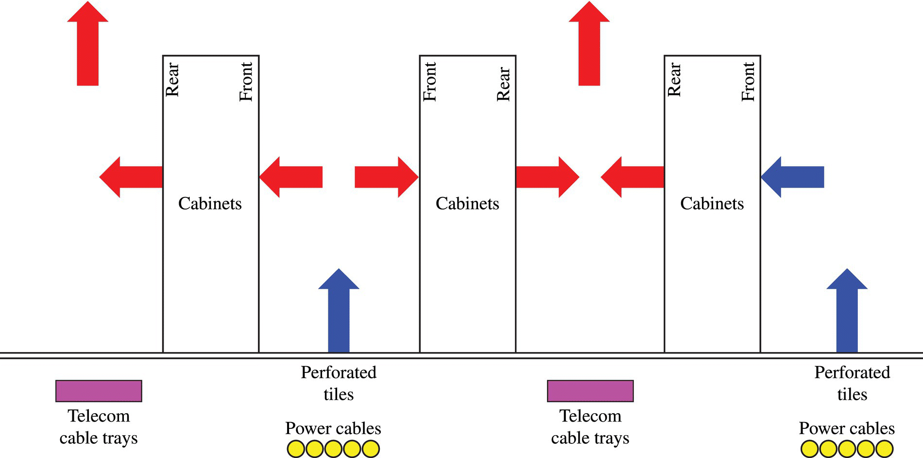
Figure 14.10 Hot and cold aisle examples.
If telecommunications cables are placed under access floors, telecommunications cables should be placed under the hot aisles so as to not restrict airflow if underfloor cooling ventilation is to be used. If power cabling is distributed under the access floors, the power cables should be placed on the floor in the cold aisles to ensure proper separation of power and telecommunications cabling (Fig. 14.10).
Lighting and telecommunications cabling shall be separated by at least 5 in.
Power and telecommunications cabling shall be separated by the distances specified in ANSI/TIA-569-C or ISO/IEC 14763-2. Generally, it is best to separate large numbers of power cables and telecommunications cabling by at least 600 mm (2 ft). This distance can be halved if the power cables are completely surrounded by a grounded metallic shield or sheath.
The minimum clearance at the front of the cabinets and racks is 1.2 m (4 ft), the equivalent of two full tiles. This ensures that there is proper clearance at the front of the cabinets to install equipment into the cabinets—equipment is typically installed in cabinets from the front. The minimum clearance at the rear of cabinets and equipment at the rear of racks is 900 mm (3 ft). This provides working clearance at the rear of the equipment for technicians to work on equipment. If cool air is provided from ventilated tiles at the front of the cabinets, more than 1.2 m (4 ft) of clearance may be specified by the mechanical engineer to provide adequate cool air.
The cabinets should be placed such that either the front or rear edges of the cabinets align with the floor tiles. This ensures that the floor tiles at both rears of the cabinets can be lifted to access systems below the access floor (Fig. 14.11).
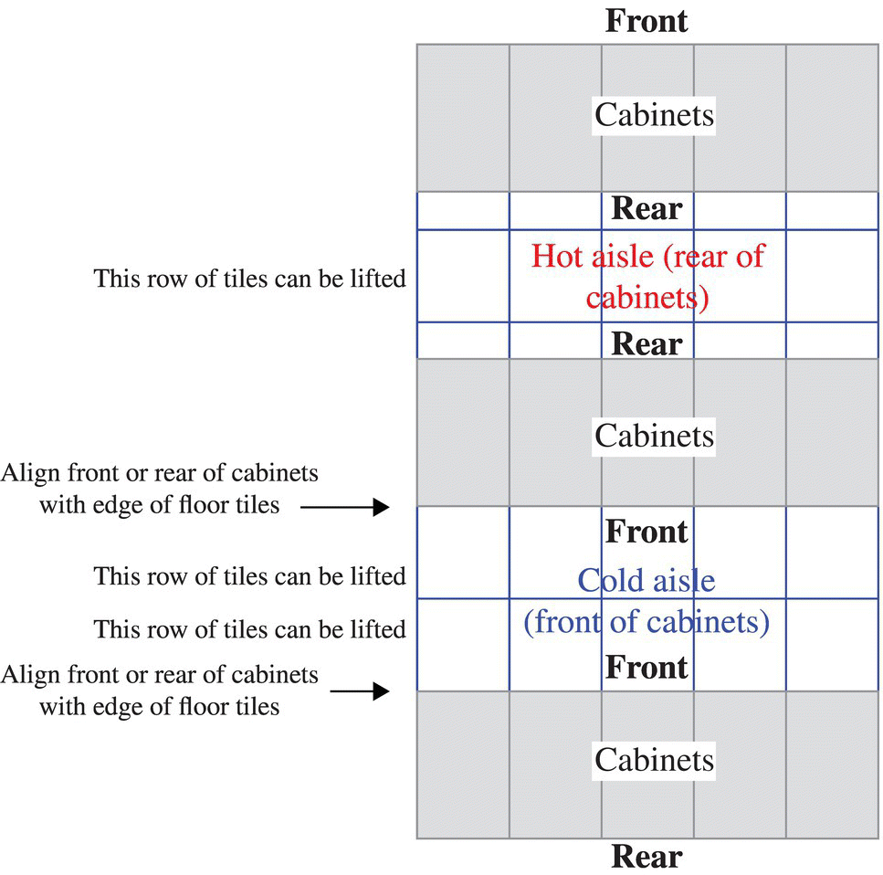
Figure 14.11 Cabinet placement example.
If power and telecommunications cabling are under the access floor, the direction of airflow from air-conditioning equipment should be parallel to the rows of cabinets and racks to minimum interference caused by the cabling and cable trays.
Openings in the floor tiles should only be made for cooling vents or for routing cables through the tile. Openings for floor tile for cables should minimize air pressure loss by not cutting excessively large holes and by using a device that restricts airflow around cables, like brushes or flaps. The holes for cable management should not create tripping hazards; ideally, they should be located either under the cabinets or under vertical cable managers between racks.
If there are no access floors or if they are not to be used for cable distribution, cable trays shall be routed above cabinets and racks and not above the aisles.
Sprinklers and lighting should be located above aisles rather than above cabinets, racks, and cable trays, where their efficiency will be significantly reduced.
14.8 Cabling and Energy Efficiency
There should be no windows in the computer room; it allows light and heat into the environmentally controlled area, which creates an additional heat load.
TIA-942-A specifies that the 2011 ASHRAE TC 9.9 guidelines be used for the temperature and humidity in the computer room and telecommunications spaces.
ESD could be a problem at low humidity (dew point below 15°C [59°F], which corresponds approximately to 44% relative humidity at 18°C [64°F] and 25% relative humidity at 27°C [81°F]). Follow the guidelines in TIA TSB-153, Static Discharge between LAN Cabling and Data Terminal Equipment, for mitigation of ESD if the data center will operate in low humidity for extended periods. The guidelines include use of grounding patch cords to dissipate ESD built up on cables and use wrist straps per manufacturers’ guidelines when working with equipment.
The attenuation of balanced twisted-pair telecommunications cabling will increase as temperatures increase. Since the ASHRAE guidelines permit temperatures measured at inlets to be as high as 35°C (95°F), temperatures in the hot aisles where cabling may be located can be as high as 55°C (131°F). See ISO/IEC 11801, CENELEC EN 50173-1, or ANSI/TIA-568-C.2 for reduction in maximum cable lengths based on the average temperature along the length of the cable. Cable lengths may be further decreased if the cables are used to power equipment, since the cables themselves will also generate heat.
TIA-942-A recommends that energy-efficient lighting such as LED be used in the data center and that the data center follow a three-level lighting protocol depending on human occupancy of each space:
- Level 1—with no occupants, the lighting level should only be bright enough to meet the needs of the security cameras.
- Level 2—detection of motion triggers higher lighting levels to provide safe passage through the space and to permit security cameras to identify persons.
- Level 3—this level is used for areas occupied for work; these areas shall be lit to 500 lux.
Cooling can be affected both positively and negatively by the telecommunications and IT infrastructure. For example, the use of the hot aisle/cold aisle cabinet arrangement described earlier will enhance cooling efficiency. Cable pathways should be designed and located so as to minimize interference with cooling.
Generally, overhead cabling is more energy efficient than underfloor cabling if the space under the access floor is used for cooling since overhead cables will not restrict airflow or clause turbulence.
If overhead cabling is used, the ceilings should be high enough so that air can circulate freely around the hanging devices. Ladders or trays should be stacked in layers in high-capacity areas so that cables are more manageable and do not block the air. If present, optical fiber patch cords should be protected from copper cables.
If underfloor cabling is used, they will be hidden from view, which will give a cleaner appearance. Installation is generally easier. Care should be taken to separate telecommunications cables from the underfloor electrical wiring. Smaller cable diameters should be used. Shallower, wider cable trays are preferred as they don’t obstruct underfloor airflow as much. Additionally, if underfloor air-conditioning is used, cables from cabinets should run in the same direction of airflow to minimize air pressure attenuation.
Either overhead or underfloor cable trays should be no deeper than 6 in. (150 mm). Cable trays used for optical fiber patch cords should have solid bottoms to prevent microbends in the optical fibers.
Enclosure or enclosure systems can also assist with air-conditioning efficiency. Consider using systems such as the following:
- Cabinets with isolated air returns (e.g., chimney to plenum ceiling space) or isolated air supply.
- Cabinets with in-cabinet cooling systems (e.g., door cooling systems).
- Hot aisle containment or cold aisle containment systems—note that cold aisle containment systems will generally mean that most of the space including the space occupied by overhead cable trays will be warm.
- Cabinets that minimize air bypass between the equipment rails and the side of the cabinet.
The cable pathways, cabinets, and racks should minimize the mixing of hot and cold air where not intended. Openings in cabinets, access floors, and containment systems should have brushes, grommets, and flaps at cable openings to decrease air loss around cable holes.
The equipment should match the cooling scheme—that is, equipment should generally have air intakes at the front and exhaust hot air out the rear. If the equipment does not match this scheme, the equipment may need to be installed backward (for equipment that circulates air back to front) or the cabinet may need baffles (for equipment that has air intakes and exhausts at the sides).
Data center equipment should be inventoried. Unused equipment should be removed (to avoid powering and cooling unnecessary equipment).
Cabinets and racks should have blanking panels at unused spaces to avoid mixing of hot and cold air.
Unused areas of the computer room should not be cooled. Compartmentalization and modular design should be taken into consideration when designing the floor plans; adjustable room dividers and multiple rooms with dedicated HVACs allow only the used portions of the building to be cooled and unoccupied rooms to be inactive.
Also, consider building the data center in phases. Sections of the data center that are not fully built require less capital and operating expenses. Additionally, since future needs may be difficult to predict, deferring construction of unneeded data center space reduces risk.
14.9 Cable Pathways
Adequate space must be allocated for cable pathways. In some cases, either the length of the cabling (and cabling pathways) or the available space for cable pathways could limit the layout of the computer room.
Cable pathway lengths must be designed to avoid exceeding maximum cable lengths for WAN circuits, LAN connections, and SAN connections:
- Length restrictions for WAN circuits can be avoided by careful placement of the entrance rooms, demarcation equipment, and wide area networking equipment to which circuits terminate. In some cases, large data centers may require multiple entrance rooms.
- Length restrictions for LAN and SAN connections can be avoided by carefully planning the number and location of MDAs, IDAs, and HDAs where the switches are commonly located.
There must be adequate space between stacked cable trays to provide access for installation and removal of cables. TIA and BICSI standards specify a separation of 12 in. (300 mm) between the top of one tray and the bottom of the tray above it. This separation requirement does not apply to cable trays run at right angles to each other.
Where there are multiple tiers of cable trays, the depth of the access floor or ceiling height could limit the number of cable trays that can be placed.
Standards and the NFPA National Electrical Code limit the maximum depth of cable and cable fill of cable trays:
- Cabling inside cable trays must not exceed a depth of 150 mm (6 in.) regardless of the depth of the tray.
- With cable trays that do not have solid bottom, the maximum fill of the cable trays is 50% by cross-sectional area of the cables.
- With cable trays that have solid bottoms, the maximum fill of the cable trays is 40%.
Cables in underfloor pathways should have a clearance of at least 50 mm (2 in.) from the bottom of the floor tiles to the top of the cable trays to provide adequate space between the cable trays and the floor tiles to route cables and avoid damage to cables when floor tiles are placed.
Optical fiber patch cords should be placed in cable trays with solid bottoms to avoid attenuation of signals caused by microbends.
Optical fiber patch cords should be separated from other cables to prevent the weight of other cables from damaging the fiber patch cords.
When they are located below the access floors, cable trays should be located in the cold aisles. When they are located overhead, they should be located above the cabinets and racks. Lights and sprinklers should be located above the aisles rather than the cable trays and cabinets/racks.
Cabling shall be at least 5 in. (130 mm) from lighting and adequately separated from power cabling as previously specified.
14.10 Cabinets and Racks
Racks are frames with side mounting rails on which equipment may be fastened. Cabinets have adjustable mounting rails, panels, and doors and may have locks. Because cabinets are enclosed, they may require additional cooling if natural airflow is inadequate; this may include using fans for forced airflow, minimizing return air flow obstructions, or liquid cooling.
Empty cabinet and rack positions should be avoided. Cabinets that have been removed should be replaced and gaps should be filled with new cabinets/racks with panels to avoid recirculation of hot air.
If doors are installed in cabinets, there should be at least 63% open space on the front and rear doors to allow for adequate airflow. Exceptions may be made for cabinets with fans or other cooling mechanisms (such as dedicated air returns or liquid cooling) that ensure that the equipment is adequately cooled.
In order to avoid difficulties with installation and future growth, consideration should be taken when designing and installing the preliminary equipment. 480 mm (19 in.) racks should be used for patch panels in the MDAs, IDAs, and HDAs, but 585 mm (23 in.) racks may be required by the service provider in the entrance room. Both racks and cabinets should not exceed 2.4 m (8 ft) in height.
Except for cable trays/ladders for patching between racks within the MDA, IDA, or HDA, it is not desirable to secure cable ladders to the top of cabinets and racks as it may limit the ability to replace the cabinets and racks in the future.
To ensure that infrastructure is adequate for unexpected growth, vertical cable management size should be calculated by the maximum projected fill plus a minimum of 50% growth.
The cabinets should be at least 150 mm (6 in.) deeper than the deepest equipment to be installed.
14.11 Patch Panels and Cable Management
Organization becomes increasingly difficult as more interconnecting cables are added to equipment. Labeling both cables and patch panels can save time, as accidentally switching or removing the wrong cable can cause outages that can take an indefinite amount of time to locate and correct. The simplest and most reliable method of avoiding patching errors is by clearly labeling each patch panel and each end of every cable as specified in ANSI/TIA-606-B.
However, this may be difficult if high-density patch panels are used. It is not generally considered a good practice to use patch panels that have such high density that they cannot be properly labeled.
Horizontal cable management panels should be installed above and below each patch panel; preferably, there should be a one-to-one ratio of horizontal cable management to patch panel unless angled patch panels are used. If angled patch panels are used instead of horizontal cable managers, vertical cable managers should be sized appropriately to store cable slack.
Separate vertical cable managers are typically required with racks unless they are integrated into the rack. These vertical cable managers should provide both front and rear cable managements.
Patch panels should not be installed on the front and back of a rack or cabinet to save space, unless both sides can be easily accessed from the front.
14.12 Reliability Levels and Cabling
Data center infrastructure levels have four categories: telecommunications (T), electrical (E), architectural (A), and mechanical (M). Each category is rated from one to four with one providing the lowest availability and four providing the highest availability. The ratings can be written as TNENANMN, with TEAM standing for the four categories and N being the rating of the corresponding category. Higher ratings are more resilient and reliable but more costly. Higher ratings are inclusive of the requirements for lower ratings. So, a data center with level 3 telecommunications, level 2 electrical, level 4 architectural, and level 3 mechanical infrastructure would be classified as TIA-942 level Rating T3E2A4M3. The overall level rating for the data center would be level 2, the rating of the lowest level portion of the infrastructure (electrical level 2).
The TIA-942 level classifications are specified in more detail in ANSI/TIA-942-A. There are also other schemes for assessing the reliability of data centers. In general, systems that require more detailed analysis of the design and operation of a data center provide a better indicator of the expected availability of a data center.
14.13 Conclusion and Trends
The requirements of telecommunications cabling, including maximum cable lengths, size, and location of telecommunications distributors, and requirements for cable pathways influence the configuration and layout of the data center.
The telecommunications cabling infrastructure of the data center should be planned to handle the expected near-term requirements and preferably at least one generation of system and network upgrades to avoid the disruption of removing and replacing the cabling.
For current data centers, this means the following:
- Balanced twisted-pair cabling should be Category 6A or higher.
- Multimode optical fiber should be OM4.
- Either install or plan capacity for single-mode optical fiber backbone cabling within the data center.
It is likely that LAN and SAN connections for servers will be consolidated. The advantages of consolidating LAN and SAN networks include the following:
- Fewer connections permit the use of smaller form factor servers that cannot support a large number of network adapters.
- Reduces the cost and administration of the network because it has fewer network connections and switches.
- It simplifies support because it avoids the need for a separate Fiber Channel network to support SANs.
Converging LAN and SAN connections requires high-speed and low-latency networks. The common server connection for converged networks will likely be 10 Gbps Ethernet. Backbone connections will likely be 100 Gbps Ethernet or higher.
The networks required for converged networks will require low latency. Additionally, cloud computing architectures typically require high-speed, device-to-device communication within the data center (e.g., server-to-storage array and server-to-server). New data center switch fabric architectures are being developed to support these new data center networks.
There are a wide variety of implementations of data center switch fabrics. See Figure 14.12 for an example of the fat tree or leaf-and-spine configuration, which is one common implementation.
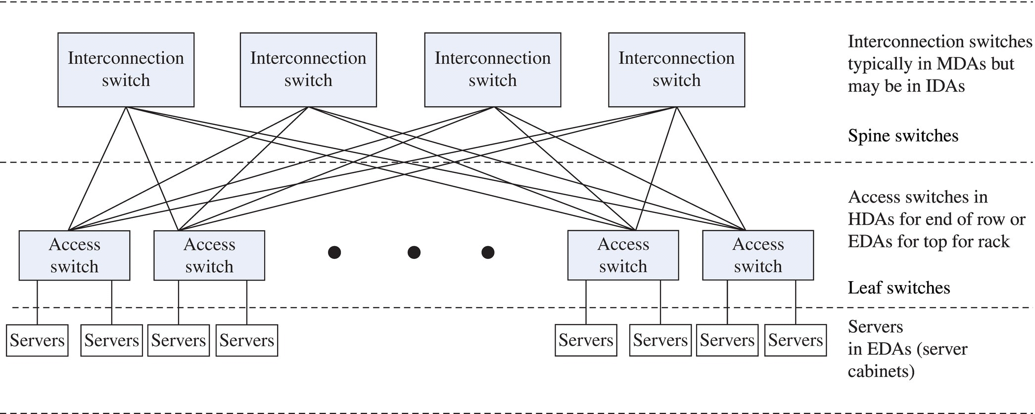
Figure 14.12 Data center switch fabric example.
The various implementations and the cabling to support them are described in ANSI/TIA-942-A-1. Common attributes of data center switch fabrics are the need for much more bandwidth than the traditional switch architecture and many more connections between switches than the traditional switch architecture.
When planning data center cabling, consider the likely future need for data center switch fabrics.
Further Reading
For further reading, see the following telecommunications cabling standards:
- ANSI/BICSI-002. Data Center Design and Implementation Best Practices Standard
- ANSI/NECA/BICSI-607. Standard for Telecommunications Bonding and Grounding Planning and Installation Methods for Commercial Buildings
- ANSI/TIA-942-A. Telecommunications Infrastructure Standard for Data Centers
- ANSI/TIA-942-A-1. Cabling Guidelines for Data Center Fabrics
- ANSI/TIA-568-C.0. Generic Telecommunications Cabling for Customer Premises
- ANSI/TIA-569-C. Telecommunications Pathways and Spaces
- ANSI/TIA-606-B. Administration Standard for Telecommunications Infrastructure
- ANSI/TIA-607-B. Telecommunications Bonding and Grounding (Earthing) for Customer Premises
- ANSI/TIA-758-B. Customer-Owned Outside Plant Telecommunications Infrastructure Standard
In Europe, the TIA standards may be replaced by the equivalent CENELEC standard:
- CENELEC EN 50173-5. Information Technology: Generic Cabling—Data Centers
- CENELEC EN 50173-1. Information Technology: Generic Cabling—General Requirements
- CENELEC EN 50174-1. Information Technology: Cabling Installation—Specification and Quality Assurance
- CENELEC EN 50174-2. Information Technology: Cabling Installation—Installation Planning and Practices Inside Buildings
- CENELEC EN 50310. Application of Equipotential Bonding and Earthing in Buildings With Information Technology Equipment
In locations outside the United States and Europe, the TIA standards may be replaced by the equivalent ISO/IEC standard:
- ISO/IEC 24764. Information Technology: Generic Cabling Systems for Data Centers
- ISO/IEC 11801. Information Technology: Generic Cabling for Customer Premises
- ISO/IEC 14763-2. Information Technology: Implementation and Operation of Customer Premises Cabling—Planning and Installation
Note that there is no CENELEC or ISO/IEC equivalent to ANSI/TIA-942-A-1, Cabling Guidelines for Data Center Fabrics. The ISO/IEC standard for telecommunications bonding and earthing is being developed.
Also note that standards are being continually updated; please refer to the most recent edition and all addenda to the listed standards.
