Since the CD, developed in the early 1980s, has almost reached its upper limitations of sound quality, Sony and Philips joined once again to develop a new system with an extremely high sound quality, surpassing the limit of CD. To review proposals, the three major trade associations of the recording industry formed the International Steering Committee (ISC). These three associations are the Recording Industry Association of America (RIAA), the Recording Industry Association of Japan (RIAJ) and Europe’s International Federation of Phonographic Industry (IFPI).
In May 1996, the ISC made a list of recommendations about the new format. Key points to these recommendations are:
• |
Active Copy Management System (ACMS) |
• |
Copyright protection |
• |
Anti-piracy measures |
• |
Compatibility |
• |
Audio, video and data storage |
• |
Conditional access |
• |
High-quality sound and multi-channel possibilities |
• |
Archive and master transfer without loss of sound quality |
• |
Extended disc functions, including text |
• |
Packaging (may not include caddy or cartridge) |
• |
Durability (more resistant or protected to scratches than CD) |
• |
|
• |
12 cm diameter is preferred |
At the same time as SACD was developed, based upon the same recommendations from the same group, the DVD-Audio format was developed. These formats are very similar and are competing to gain acceptance within the same public. The underlying design and technology are also similar, and as both technologies will be explained within this book, a number of cross references cannot be avoided.
At the end of 1999, Sony launched its new Super Audio CD (SACD) player, meeting all the requirements of the ISC. The new SACD format allows mainly a much higher dynamic and frequency range compared to the conventional CD. The introduction of Direct Stream Digital (DSD) essential to SACD (see overview of the A/D conversion systems) implies a higher quality of A/D–D/A conversion.
Besides SACD, the Super Audio CD players are capable of playing conventional CDs.
Starting with the SCD1 and SCD777ES, Sony introduced the first generation of SACD players that were capable of reproducing signals of over 100 kHz with a dynamic range of above 120 dB in the audible range. To avoid high-frequency problems when connecting the SACD player to a conventional sound system, a switch to select standard and custom mode is mounted on the set. The standard mode has to be selected when the set is connected to a conventional amplifier. In this position, the high-frequency components above 50 kHz will be attenuated, avoiding possible damage to audio systems not designed to handle such high frequencies.
The custom mode can be selected when the set is connected to the Sony pre-amplifier TA-E1 and power amplifier TA-N1 in combination with the speaker system SS-M9ED. The maximum frequency range will be output.
With the SCD-XB940 (April 2000), Sony introduced the second generation of SACD players.
Technical specifications and dimensions
In Table 18.1, a comparison of the main CD and SACD parameters is given.
Table 18.1 CD and SACD parameters
| Item | SACD | CD |
| Disc diameter (cm) | 12 | 12 |
| Disc thickness (mm) | 1.2 | 1.2 |
| Playback side | One | One |
| Disc type | 3 (single, dual, hybrid) | 1 |
| Coding system | 1-bit DSD | 16-bit PCM |
| Sampling frequency | 2.8224 MHz | 44.1 kHz |
| Data capacity (MB) | 4700 (single layer) 8540 (dual layer) | 780 |
| Min. pit length (μm) | 0.40 | 0.83 |
| Track width (μm) | 0.74 | 1.6 |
| Laser wavelength (nm) | 650 | 780 |
| Lens aperture rate | 0.60 | 0.45 |
| Playback frequency range | DC – over 100 kHz | 20 Hz–20 kHz |
| Dynamic range | More than 120 dB | 96 dB |
| Max. recording time (min) | Approx. 110 (two channels/single layer) |
74 |
| Max. track number | 255 | 99 |
| Max. index number | 255 | 99 |
| Linear velocity (m s–1) | 3.49 | 1.2 or 1.4 |
| Modulation method | EFM+ | EFM |
| Additional functions | Text, graphics, video | CD text |
Optical block structure
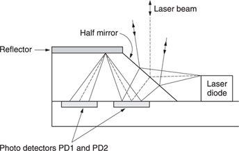
Compared to the optical bock of the CD player, the two-axis device is much finer. The numerical aperture (NA), on the other hand, is higher. The effect of a higher NA is, besides a narrower focal depth and a smaller focal point, a lower tilt tolerance and a disc thickness that becomes stricter.
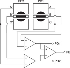
Another difference is that instead of one main photo detector with four fields (for RF detection in CD) and two side spots for tracking, two identical photo detectors (PD1 and PD2) with four fields are used for SACD.
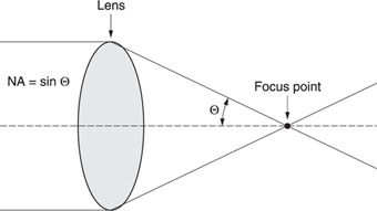
Figure 18.1 Numerical aperture.
Figure 18.2 Photo coupler.
For focus and tracking, different additions and subtractions are made to define the error voltage.
The tracking is done with the TOP PUSH PULL principle. The tracking error signal is calculated as follows:
TE = (C + A′+ B2 + B1′) – (A + C′ + B1 + B2′)
In Figure 18.3, the ‘on track’ situation is presented. In case the laser beam shifts to the ‘off track’ position, the position of the reflection on the photo detector will also shift with a corresponding error signal as a result.
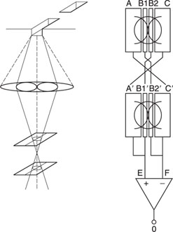
Figure 18.3 Tracking.
Figure 18.4 On focus.
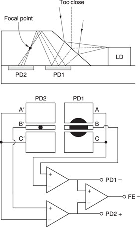
Figure 18.5 Off focus.
Focus is performed with the differential three-divided focus (D-3DF) principle. The same two photo detectors are used but B1 and B2 (B1′and B2′) are connected as one detector field.
Focus error voltage will be:
FE = [B – (A + C)] – [B′ – (A′ + C′)]
Figure 18.4 represents the situation where a good focus is obtained. In this situation, both reflections are equal and the output voltage will be zero.
In case the laser beam is out of focus, the reflection on PD1 will be different from PD2 and an error voltage is generated (see Figure 18.5).
The same disc diameter is used for SACD as for CD. The maximum dimensions of the pits are different from CD. These are much smaller (0.4 μm) for SACD than for CD (0.83 μm). Also, the track width is about half of the track width of CD. The layer with these specifications is called the HD layer.
It becomes clear that the data storage capacity on this HD layer is much higher. For a single-layer disc, the storage capacity is about seven times higher than the conventional CD. The physical structure of SACD is very similar to DVD.
Three different types of disc are used.
(a) |
Single-layer disc (SL disc) (Figure 18.6) Consists of one HD layer and has a storage capacity of 4.7 GB |
(b) |
Dual-layer disc (DL disc) (Figure 18.7) Consists of two HD layers for extended playback time. The storage capacity of this disc is about 8.5 GB. The disc thickness will be the same as the SL disc (1.2 mm). The two different layers are 0.6 mm apart. |
(c) |
Hybrid disc (Figure 18.8) To be compatible with the conventional CD, this is a unique feature of SACD, as the disc consists of two totally different layers. One layer is the HD layer and can be played back only by the SACD player. The second layer, a CD layer, can be read by both the SACD and the conventional CD player is present on this disc. This possibility of backward compatibility is a major feature which sets SACD apart from other formats. Also for the hybrid disc, where the total thickness is 1.2 mm, the high-density layer is situated in the middle of the disc or at 0.6 mm from the surface. |
The HD layer of the hybrid disc is semi-transparent and will be invisible for the CD laser beam with a numerical aperture of 0.45 and a wavelength of 780 nm. The layer will become reflective for the SACD laser beam only.
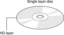
Figure 18.6 Single-layer disc.
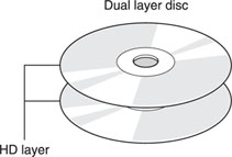
Figure 18.7 Dual-layer disc.
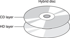
Figure 18.8 Hybrid disc.
Disc type detection
In order to discriminate the type of disc that is inserted into the set, the difference in reflectivity and distance between the two layers is detected. While reading out the RF signal, the objective lens will be moved from the lower position to the upper. During this movement, the focus point will scan the thickness of the disc. At the place where the focus point reaches the surface of the disc, a small reflection will be returned to the detector, with a pulse on the RF output resulting. This pulse is the trigger of the timer into the microprocessor. Depending on the time between the first and second pulses (where the focus point reaches the second reflective layer), the set can discriminate the presence of a high-density layer in the middle of the disc. Remember that the disc thickness is 1.2 mm with an HD layer of 0.6 mm in the case of a DL or Hybrid disc.
Table 18.2
| CD red book – compatible layer | Super Audio HD layer | |
| Reflectivity | Reflective | Semi-reflective |
| Minimum pit length (μm) | 0.83 | 0.4 |
| Track pitch (μm) | 1.6 | 0.74 |
| Laser wavelength (nm) | 780 | 650 |
| Lens numerical aperture | 0.45 | 0.6 |
Next, a discrimination of the upper layer has to be made. In the case of a dual-layer high-density disc, the reflection will be much lower compared to a CD layer on a Hybrid disc, that has to meet the specifications of the ‘red book’. The difference in reflection is detected by reading out the tracking error voltage while moving the optical block from the centre to the outer circumference (focus servo is on). Depending on the level of the signal that is output from the TE servo, the judgement of CD/HD layer can be performed.
To avoid illegal reproduction, another request from the ISC was to include an anti-piracy system. SACD also meets this requirement. Both a visible and an invisible watermark are included in this system. Detailed information is not open to the public. For this reason, we will limit this explanation to a short description of both systems.
Visible watermarking
As the name itself implies, a visible watermark is a faint image printed on the signal side of the disc. This printing is hard to copy and hard to apply to the disc, since it must not disturb the reflection of the reading laser beam. A visible watermarking cannot be detected by the set. It gives the user the possibility of checking the disc by just looking at it. Visible watermarking is recommended by the ISC but is not obligatory.
Table 18.3
| Disc type | Reflection (%) |
| Single layer | 60–85 |
| Dual layer | 18–30 |
| Hybrid disc | 15–30 (HD layer) |
| > 70 (CD layer) |
Invisible watermarking
Invisible watermarking is a copyright protection system that has to be included in the disc. This type of protection is written on the disc substrate itself and makes it impossible for the set to read the disc in the case of an illegal copy. The idea behind invisible watermarking is to include the copyright protection information into the main signal but to remain ‘invisible’ to the original audio data.
To encode the copyright protection information into the signal, a new technology called Pit Signal Processing (PSP) has been developed. The basic feature in PSP is that the laser power of the beam on the recording side is modulated. A higher laser power results in a larger laser beam, changing the length and width of the pits.
The analog input signal is converted to a DSD digital signal and divided into blocks of 2016 bytes of audio information per block.
Besides the audio information, also a great deal of supplementary data and synchronization has to be recorded on the SACD. Starting with a sampling frequency of 2.8224 MHz in a 1-bit system, the total amount of music data for 1 second of stereo music is 2 × 2 822 400/8 or 705.6 kbyte. Compared to the conventional CD (44.1 kHz, 16-bit) with 176.4 kbyte per second of music, this is four times the amount of data.
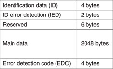
The main data are divided into blocks of 2048 bytes, which consists of 2016 bytes of audio information, header and supplementary information. Together with 4 bytes of Identification Data (ID), 2 bytes of ID Error Detection (IED) and 4 bytes of Error Detection code (EDC), a data sector is formed. Also, 6 bytes are reserved for expansion, resulting in 2064 bytes per data sector (Figure 18.9).
Thanks to the evolution to the more powerful Reed–Solomon Product Code (RSPC), error correction can be done over a much larger amount of data compared to the CIRC error correction for CD.
Figure 18.9 Data sectors.
The error correction information is applied to 16 data sectors, creating an ECC block.
The 2064 × 16 data bytes are scrambled into a matrix of 192 rows by 172 columns. Ten PI parity bytes are added to each row and 16 PO parity bytes are added to each column. With RSPC, at least 5 byte errors per row and 8 byte errors per column can be corrected. Several calculations after each other can even correct larger errors.
After this, the 192 data rows of the ECC block are divided into 16 blocks of 12 rows and the 16 PO rows are interleaved between the 16 blocks. In this way, a recording sector is created.
In fact, a recording sector consists of the information of one data sector (12 rows) or 2064 bytes + 12 × 10 PI bytes + 1 row of 182 PO bytes, or 2366 bytes.
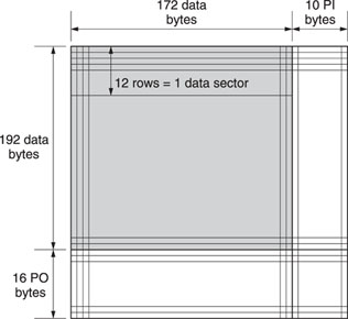
Figure 18.10 ECC block.
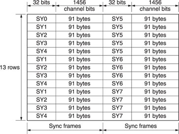
Now, each row of the recording sector is divided into two parts of 91 bytes. EFM+ is applied to each byte and a sync word of 32 bits is added to each part. The sync words are alternatively added to the pattern in a logical way, allowing the decoders to synchronize their timing.
Each sync word has a specific ‘identification’ pattern and a specific place in the physical sector:
SYNC0: |
Start of the physical sector |
SYNC1…4: |
Start of an odd sync frame |
SYNC5…7: |
Start of an even sync frame |
The pattern of the sync words are chosen from the additional list of words that meet the EFM recommendations (refer to EFM+), so no supplementary EFM conversion has to be applied to these sync words.
Using eight different sync words to the 13 rows of the recording sector results in a physical sector that consists of 13 × 2 (sync words per row) × (32 (sync bits) + 91 bytes × 2 (EFM+) × 8 (bits)) = 38 688 bits.
If we now return to the calculation of the data bit rate. One data sector has 2048 bytes of main data. Now, two different structures have been defined for the SACD format. A three-frame/ 14-sector and a three-frame/16-sector system.
In the case of a three-frame/14-sector system, the total amount of audio data in 14 sectors is 28 224 bytes. The rest is 84 bytes header information and 364 bytes supplementary data, giving a total of 14 × 2048 or 28 672 bytes.
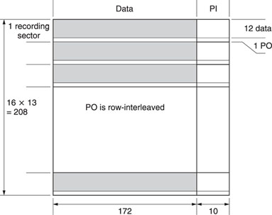
Figure 18.11 Recording sector.
One second of reading has 75 frames, meaning that the total audio data stream is 75/3 (three-frame system) × 28 224 (audio data per sector) or 705 600 bps.
A similar calculation can be performed for the three-frame/ 16-sector system, where the amount of supplementary data is different.
It becomes clear that the same conversion cannot be adopted for multi-channel purposes. The final bit rate would be too high, exceeding the maximum reading speed of the optical system. Therefore, the Direct Stream Transfer (DST) compression technique is used to reduce the amount of data and as a consequence the transfer speed. DST will be explained later.
The final definition for the Maximum Byte rate in the SACD version 1.1 format book for the audio and supplementary data is:
2CH (three frames/14 sectors): 716 800 B s–1 or 5.7344 Mbps
2CH (three frames/16 sectors): 819 200 B s–1 or 6.5536 Mbps
Multi-channel (DST): 1 873 920 B s–1 or 14.99136 Mbps
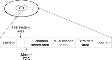
Three main areas are defined in the structure of the SACD disc. The innermost area or lead-in zone, where the information of the disc types (factory information, number of disc layers, etc.) is recorded, the program zone or data zone, and the lead-out zone. This last zone is used as a buffer zone in case the optical block is moved to the outer zone due to a shock. In the case of the Hybrid disc, where the upper layer has the same structure as a conventional CD, the lead-in zone of this CD layer also contains the table of contents. The middle zone for the dual-layer disc is different from the single-layer and Hybrid discs. Basically, the middle zone has the same function as the lead-out zone.
The Data zone of the SACD contains the TOC information together with the file system area, the Audio area and the Extra data area.
Figure 18.16 shows the complete structure recorded on the disc.
The file system area is an optional space where the information defined in the ISO-9660 or Unique Disc File (UDF) can be recorded.
Figure 18.12 Physical sector.

Figure 18.13 Hybrid disc.

Figure 18.14 Single-layer disc.

Figure 18.15 Dual-layerdisc.
Different from CD, where the TOC holds the information about the number of tracks and the time recorded on the disc, the master TOC area used for SACD has information about the album and disc.
The main items in this master TOC are:
• |
Position and size of the area TOC. |
• |
Disc and Album information (all information about disc type, disc catalogue number, genre, date and time, etc.). |
• |
Text information (amount of text channels on the disc, language, etc.). |
• |
Text (disc name, name of the artist, etc.). |
Figure 18.16 Data structure.
Taking a closer view of the Audio area, consisting of a Two-channel Stereo area and a Multi-channel area, shows that these areas are divided into three main blocks:
Both TOC1 and TOC2 contain the same information about the numbers of tracks recorded on the disc, total playing time, position of the different tracks, etc. The purpose of recording the same TOC information twice is for safety reasons in case the TOC1 area is damaged.
The actual audio data are recorded in the track area.
The extra data area is an optional part on the disc to record the data of the UDF or ISO9660 file system.
As explained before, it is recommended by the ICS to store 74 minutes of two-channel high-quality sound or six-channel high-quality surround sound on the 4.7 GB HD layer of the optical disc. If we make a rough calculation of the memory needed for a stereo sound of 74 minutes, we can see that it would be impossible to record six-channel sound with the same specifications.
74 × 60 × 2 × 2.8224 MHz/8 or about 3.2 GB (for two channels)
In order to make it possible to record the six-channel information, data reduction has to be adopted. Two different options were possible. A lossy compression method based on psychoacoustics, like Dolby Digital (AC3), or a lossless coding method.
The SACD format has chosen to use the new lossless coding: Direct Stream Transfer (DTS). Lossless coding methods were originally developed to reduce the amount of data for PC applications. After decoding, the original signal can be reconstructed bit for bit.
DTS is a very complex coding method, using framing, adaptive prediction and entropy encoding stages.
Entropy is based on the appearance probability of the symbols. A symbol that appears frequently has the shortest code, a symbol that does not appear frequently has the longest code. In this way, a substitution table of the most frequently appearing symbols can be formed.
A second basic method of reducing the amount of data is to shorten the code words. Instead of sending eight consecutive zero bits, a simple 8 × 0 will be encoded.
However, for DSD signals, the basic entropy method is not very efficient, since amplitude is converted into a bit stream and not into an absolute value as for PCM.
Therefore, a new adaptive prediction method has been developed. With this new method, DTS is capable of reducing the total amount of data by about 50% without losing any information.
The structure of a lossless coding system is shown in Figure 18.18. The input signal is framed to select an appropriate part. On this selection, prediction is done to remove redundancy. The entropy encoder will make the most efficient coding of the input signal.

Figure 18.17 Track/channel structure.
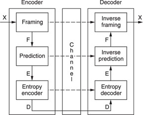
Figure 18.18 Structure of a lossless coding system.
Due to the adoption of the techniques of framing, prediction and entropy encoding, the final bit rate of a DTS encoder is not constant. A constant bit rate is desired in systems working with an optical disc system, since this corresponds with a constant linear disc speed. By adding a buffer control, the variable bit rate can be converted to a constant bit rate.
In conclusion, adaptive prediction used for DTS reduces the high bit rate of multi-channel DSD to store the entire 74 minutes of information on a single-layer disc.
With the SACD, Sony and Philips created a new standard that fulfils all the high-quality needs for the next generation of sound carriers. The SACD can serve not only for sound reproduction for home use, but also as a high-quality archiving system to replace the analog tape in recording studios.
Thanks to the sophisticated watermarking technology, the new format will also defeat piracy.
An additional advantage is that, with the hybrid disc, the SACD guarantees 100% compatibility with existing CD players.

