Introduction to Part 2
We consider here the problem of the transmission of a series of binary and M-ary symbols on a transmission channel characterized by its limited bandpass of the “low-pass” type and of band-pass type as well as the associated random disturbances, the channel noise.
If the source delivers an analog message such as the speech signal (output of a microphone) or the video signal (output of an analog camera), then it should be digitized. This operation is done by sampling the analog message while respecting Shannon’s theorem (fe ≥ 2fmax), then by quantifying the samples obtained with Q = 2m levels and finally by coding each sample with m binary elements.
The transmission media of the “low-pass” type are the two-wire and coaxial electrical cables and the optical cables. The bandwidth of twisted pair cables is low. They are generally used for transmissions around 2 Mbit/s or 8 Mbit/s on the telephone network. The bandwidth of coaxial cables is greater than that of two-wire cables. They are used, with optical fibers, to connect telephone exchanges with a bitrate which can reach Gbit/s. Optical fibers are distinguished by a very high bandwidth (several tens of Gbit/s) and a very low attenuation compared to that of metallic cables. They are used for terrestrial networks, for submarine cables (they replace coaxial cables), as well as for distribution networks (connections between telephone exchanges and subscribers).
Channel noise has various origins, such as high-voltage lines, high-speed trains, motors, various radiations, possible interferences between different users of the transmission medium, internal noise from the electronic devices used, etc.
Transmission media of the “bandpass” type are the analog telephone channel, the radio channel, the mobile radio channel and the earth-satellite channel. Carrier frequency digital transmissions differ from digital baseband transmissions by the types and properties of the digital modulations used, as well as by the types and characteristics of radio degradations.
Finally, note that digital baseband transmissions form a general problem, the solution of which applies to all forms of digital transmission. Indeed, we will see in Chapter 7 that digital transmissions with carriers, through a bandpass filter, can be reduced to the simpler and more universal case of transmission through an equivalent low-pass filter.
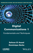
Figures I2.1 and I2.2 respectively demonstrate the block diagram of a digital baseband transmission and the general diagram of a digital radio transmission system.
In this second part, we will address the following three issues:
- – the binary to M-ary coding and M-ary to signal coding: online codes (Chapter 5);
- – the transmission over a low-pass channel of an M-ary digital signal (Chapter 6);
- – the digital transmissions with carrier modulation (Chapter 7).
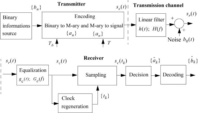
Figure I2.1. General diagram of a digital radio transmission system
Figure I2.2. General diagram of a digital radio transmission system