
8
Harmonic Speech Coding
8.1 Introduction
A general sinusoidal analysis and synthesis concept was introduced by McAulay [1] when he developed the Sinusoidal Transform Coder (STC) [2] to demonstrate the applicability of the technique in low bit-rate speech coding. Sinusoidal coding does not restrict the component sinusoids of the synthesized speech to be harmonics of the fundamental frequency. The frequency tracks of the sinusoids may vary independently of each other. However in harmonic coding the higher frequency sinusoids are restricted to be integer multiples of the fundamental frequency [3]. Therefore harmonic coding can be seen as a subset of a generalized sinusoidal transform coding. At low bit-rates, STC also restricts the frequency tracks to be harmonics of the fundamental frequency, and deduces the harmonic phases at the decoder, simply because the available bits are not sufficient to encode the large number of parameters of the general sinusoidal representation.
The STC was introduced as an alternative to the source filter model, and its analysis and synthesis was directly applied to the original speech signal. The binary voicing decision of the source filter model is one of its major limitations. The STC employs a more general mixed-voicing scheme by separating the speech spectrum into voiced and unvoiced components, using a voicing transition frequency above which the spectrum is declared unvoiced. However, one of the most recent harmonic coders operates in the LPC residual domain, i.e. Split Band LPC (SB-LPC) [4]. SB-LPC replaces the binary excitation of the source-filter model with a more general mixed excitation, and filters the excitation signal using an LPC filter. The LPC residual has a simpler phase spectrum than the original speech. The residual harmonic phases can be approximated by using the integrals of the component frequencies. Moreover, LPC models the large variation in the speech magnitude spectrum and simplifies the harmonic amplitude quantization.
8.2 Sinusoidal Analysis and Synthesis
Figure 8.1 depicts block diagrams of the sinusoidal analysis and synthesis processes introduced by McAulay. The speech spectrum is estimated by windowing the input speech signal using a Hamming window and then computing the Discrete Fourier Transform (DFT). The frequencies, amplitudes, and phases corresponding to the peaks of the magnitude spectrum become the model parameters of the sinusoidal representation. Employing a pitch-adaptive analysis window length of two and a half times the average pitch improves the accuracy of peak estimation. The synthesizer generates the sine waves corresponding to the estimated frequencies and phases, and modulates them using the amplitudes. Then all the sinusoids are summed to produce the synthesized speech. The block edge effects are smoothed out by applying overlap and add, using a triangular window. Overlap and add is effectively a simple interpolation technique and, in sinusoidal synthesis, it requires parameter update rates of at least every 10–15 ms for good quality speech synthesis. At lower frame rates the spectral peaks need to be properly aligned between the analysis frames to form frequency tracks. The amplitudes of the frequency tracks are linearly interpolated, and the instantaneous phases are generated using a cubic polynomial [1] as shown in Figure 8.2.
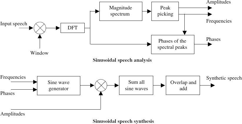
Figure 8.1 General sinusoidal analysis and synthesis
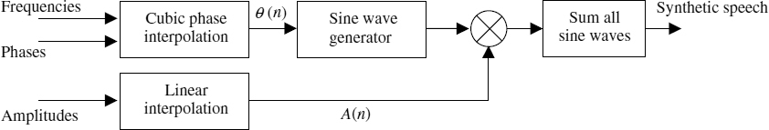
Figure 8.2 Sinusoidal synthesis with matched frequency tracks
8.3 Parameter Estimation
Low bit-rate sinusoidal coders estimate the amplitudes at the harmonics of the fundamental frequency. At low bit-rates, the harmonic phases are not transmitted. Instead the phases are deduced from the spectral envelope on the assumption that it is the gain response of a minimum phase transfer function and added to the integrals of the component frequencies. STC implements the harmonic phases explicitly and LPC-based coders implement the phases implicitly through the time-domain LPC synthesis filter. Improved multiband excitation (IMBE) coders do not use any kind of phase information and the phases are evolved as the integrals of the component harmonic frequencies. Restricting the component frequencies to the harmonics and modelling the phases at the decoder is well suited for stationary voiced segments of speech. However, in general, the speech signal is not stationary voiced and consists of a mixture of voiced and unvoiced segments. When those segments are synthesized with the phase models described above, the synthesized speech sounds buzzy. In order to remove this ‘buzzyness’ the concept of frequency-domain voicing was introduced into low bit-rate harmonic coders [5]. Frequency-domain voicing allows the synthesis of mixed voiced signals, by separating the speech spectrum into frequency bands marked as either voiced or unvoiced.
Frequency-domain voicing decisions are usually made for each harmonic of the speech spectrum. Therefore, an accurate pitch estimate is a prerequisite of harmonic amplitude and voicing determination. The frequency-domain voicing determination techniques based on spectral matching need a high precision pitch estimate for good performance. A small error in the pitch will cause large deviations at the high frequency harmonics, and subsequent declaration of them as unvoiced. Furthermore, female voices with short pitch periods are more sensitive to small pitch error. In order to reduce the complexity of a high-precision pitch estimation, an initial pitch estimate is usually further refined by performing a limited search around the initial estimate. Having determined an accurate pitch the harmonic coding usually proceeds with voicing and spectral amplitude estimation processes.
8.3.1 Voicing Determination
There are many ways of performing the voicing classification of speech, which was discussed in Chapter 6, but here we briefly summarize two common techniques.
Multi-Band Approach
Harmonic voicing is estimated by computing the normalized mean squared error of a synthetic voiced spectrum, ![]() , with respect to the speech spectrum, Sw(ω), and comparing it against a threshold function for each harmonic band [6]. The normalized mean squared error, Dk, of the kth harmonic band is given by,
, with respect to the speech spectrum, Sw(ω), and comparing it against a threshold function for each harmonic band [6]. The normalized mean squared error, Dk, of the kth harmonic band is given by,
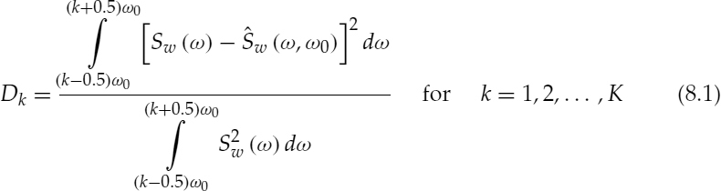
where ![]() and ω0 is the normalized fundamental frequency. Figure 8.3 illustrates Dk values of two speech spectra with the corresponding synthetic spectra. If Dk is below the threshold function, i.e. a small error and a good spectral match, the kth band is declared voiced. The initial multi-band excitation (MBE) coders used a constant threshold for all the bands. However the most recent versions use several heuristic rules to obtain a better performance [7], e.g. as the frequency increases the threshold function is decreased, if the same band of the previous frame was unvoiced, if the high-frequency energy exceeds the low-frequency energy, and if the speech energy approaches the energy of the background noise.
and ω0 is the normalized fundamental frequency. Figure 8.3 illustrates Dk values of two speech spectra with the corresponding synthetic spectra. If Dk is below the threshold function, i.e. a small error and a good spectral match, the kth band is declared voiced. The initial multi-band excitation (MBE) coders used a constant threshold for all the bands. However the most recent versions use several heuristic rules to obtain a better performance [7], e.g. as the frequency increases the threshold function is decreased, if the same band of the previous frame was unvoiced, if the high-frequency energy exceeds the low-frequency energy, and if the speech energy approaches the energy of the background noise.
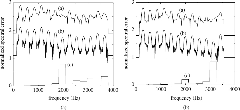
Figure 8.3 Two speech spectra: (a) original spectrum Sw(ω), (b) synthetic spectrum ![]() , and (c) normalized Dk
, and (c) normalized Dk
Sinusoidal Model Approach
McAulay et al. proposed a different voicing determination technique for his sinusoidal transform coder (STC) [2]. The speech spectrum is divided into two bands, determined by a voicing transition frequency above which the spectrum is declared unvoiced. This method estimates the similarity between the harmonically-synthesized signal, ![]() , and the original speech signal s(n). The signal to noise ratio (SNR), δ, between
, and the original speech signal s(n). The signal to noise ratio (SNR), δ, between ![]() is given by,
is given by,

where N is the analysis frame length and ![]() is given by
is given by
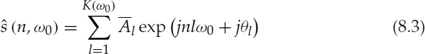
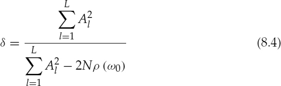
where the harmonic amplitudes, ![]() , are obtained from the spectral envelope and θl are the harmonic phases. McAulay simplified equation (8.2) for reduced computational complexity, and the simplified δ is given by,
, are obtained from the spectral envelope and θl are the harmonic phases. McAulay simplified equation (8.2) for reduced computational complexity, and the simplified δ is given by,
where Al are the harmonic-frequency spectral amplitudes of the original signal as shown below,
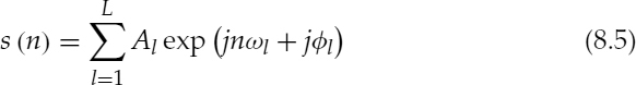
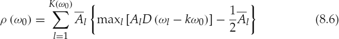
where ![]() ,
,
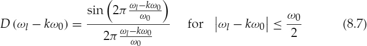
and D (ωl − kω0) = 0 otherwise.
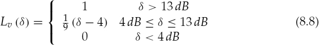
The voicing level (probability), Lv(δ) (i.e. the ratio of the voiced bandwidth to the speech bandwidth, 0 ≤ Lv (δ) ≤ 1), is defined as,
The advantage of estimating the voicing for independent bands is that it essentially removes the spectral tilt, i.e. all the components are equally weighted. When the voicing is based on a single metric, i.e. δ, the large amplitudes contribute more to the overall decision. If they have been corrupted by background noise, it may result in a large voicing error [2]. Therefore, the voicing estimates based on independent bands are more robust against background noise.
8.3.2 Harmonic Amplitude Estimation
The harmonic coding algorithms require the spectral amplitudes of the harmonics, which can be estimated in a number of ways.
Peak-picking of the Magnitude Spectrum
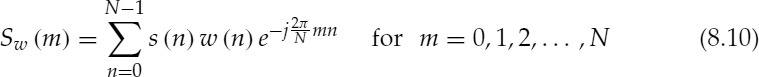
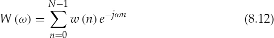
Harmonic amplitudes may be estimated by simple peak-picking of the magnitude spectrum and searching for the largest peak in each harmonic band. The peak amplitude value, Sw(mk) should be normalized by a factor depending on the window function used, as follows:

where ω0 is the normalized fundamental frequency, ![]() ,
, ![]()
 , w(n) is the window function, N is the length of the window, and Sw(m), the windowed speech spectrum, is given by,
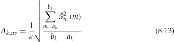
Spectral Correlation
Harmonic amplitudes may be estimated by computing the normalized cross-correlation between the harmonic lobes of the speech spectrum and the main lobe of the window spectrum. This method is based on the fact that the spectrum of the windowed speech is equivalent to the convolution between the speech spectrum and the window spectrum. It is also assumed that the speech signal is stationary during the windowed segment and the spectral leakage due to the side lobes of the window spectrum is negligible.
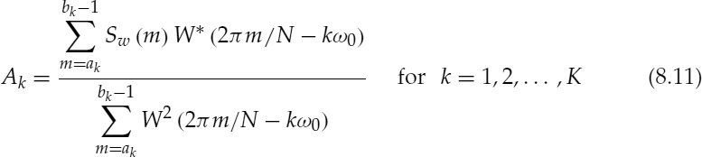
where ![]() and bk = min [ak+1, N/2], and W(ω) is the spectrum of the window function, given by,
and bk = min [ak+1, N/2], and W(ω) is the spectrum of the window function, given by,
In practice, W(ω) is computed with a high-resolution FFT, e.g. 214 samples, by zero-padding the window function, and stored in a lookup table. The high-resolution FFT is required because, in general, the spectral samples m of Sw(m) do not coincide with the harmonic locations, kω0, of the fundamental frequency. Hence W(ω) is shifted to the harmonic frequency and down-sampled to coincide with the corresponding spectral samples of Sw(m), as shown in equation (8.11). W(ω) is pre-computed and stored in order to reduce the computational complexity.
The spectral cross-correlation-based amplitude estimation gives the optimum gain of the harmonic lobes with respect to the main lobe of the window spectrum, hence it is a more accurate estimate than the simple peak-picking. However the cross-correlation-based method has a higher complexity and requires a high-precision pitch estimate.
The unvoiced amplitudes are calculated as the rms spectral energy over the unvoiced spectral bandwidth, given by,
The harmonic amplitude estimation techniques described may be applied to either the speech spectrum or the LPC residual spectrum.
8.4 Common Harmonic Coders
This section describes three examples of low bit-rate harmonic coders: sinusoidal transform coding (STC) [2], improved multi-band excitation (IMBE) [8], and split-band linear predictive coding (SB-LPC) [4]. The STC and IMBE apply sinusoidal analysis and synthesis techniques to the original speech signal and SB-LPC uses the LPC residual signal. All three examples restrict the synthesis of sinusoidal components to be harmonics of the fundamental frequency.
8.4.1 Sinusoidal Transform Coding
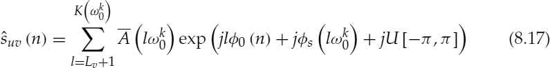
The sinusoidal transform coding (STC) operating at 4.8 kb/s divides the speech spectrum into two voicing bands using the sinusoidal model approach described in Section 8.3.1. The lower part of the spectrum, which is declared as voiced, is synthesized as follows:

where
and
where N + 1 is the frame length, ![]() is the normalized fundamental frequency of the kth frame, N′ is the duration between the analysis points,
is the normalized fundamental frequency of the kth frame, N′ is the duration between the analysis points, ![]() is the spectral envelope obtained by interpolating the selected peaks of the magnitude spectrum,
is the spectral envelope obtained by interpolating the selected peaks of the magnitude spectrum, ![]() s(ω) is the phase spectrum derived from the spectral envelope on the assumption that it is the gain response of a minimum phase transfer function, and Lv is the harmonic just below the voicing transition frequency.
s(ω) is the phase spectrum derived from the spectral envelope on the assumption that it is the gain response of a minimum phase transfer function, and Lv is the harmonic just below the voicing transition frequency.
The upper part of the spectrum, which is declared as unvoiced, is synthesized as follows:
where ![]() and U [−π, π] denotes a uniformly distributed random variable in the range −π and π. When a frame is fully unvoiced the pitch estimate is meaningless and pitch frequencies greater than 150 Hz may degrade the perceptual quality of unvoiced speech. In order to synthesize the noise-like unvoiced speech with adequate quality, the number of sinusoids with random phases should be sufficiently large. Therefore, the pitch frequency is set to 100 Hz for unvoiced speech. The synthesized speech of the kth frame is then given by,
and U [−π, π] denotes a uniformly distributed random variable in the range −π and π. When a frame is fully unvoiced the pitch estimate is meaningless and pitch frequencies greater than 150 Hz may degrade the perceptual quality of unvoiced speech. In order to synthesize the noise-like unvoiced speech with adequate quality, the number of sinusoids with random phases should be sufficiently large. Therefore, the pitch frequency is set to 100 Hz for unvoiced speech. The synthesized speech of the kth frame is then given by,
The overlap and add method is used with a triangular window to produce the final speech output. Therefore, the frame length is equal to twice the duration between the analysis points, i.e. N = 2N′. The frequency response of the spectral envelope is given by,
which is approximated by an all-pole model,
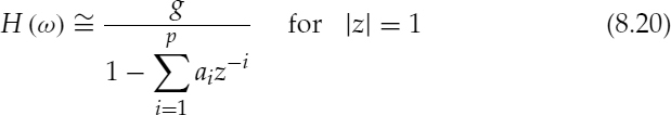
where g is the gain and ai are the predictor coefficients. The conventional time-domain all-pole LPC analysis is performed on the original speech signal and the maximum filter order is usually limited to half the smallest pitch period. The limitation is imposed so that the LPC models the formant spectral envelope, since LPC filters with a large number of taps tend to resolve the harmonic structure. However in the case of STC, all-pole modelling is applied to the estimated spectral envelope. Hence, the filter order is not restricted and can be increased depending only on the desired accuracy of the spectral envelope and the bit rate. The 4.8 kb/s STC uses a 14th–order all-pole model and quantizes the predictor coefficients in the LSF domain. In addition to the LSFs, the STC transmits gain, pitch, and voicing.
8.4.2 Improved Multi-Band Excitation INMARSAT-M Version
Improved multi-band excitation (IMBE) operating at 4.15 kb/s for INMARSAT-M divides the speech spectrum into several voiced and unvoiced frequency bands, using the multi-band approach described in Section 8.3.1. However, IMBE makes the voicing decisions for groups of three harmonics and a single bit is allocated for each group. The total number of voicing bits Bv is limited to a maximum of 12 and the harmonics beyond the coverage of voicing are declared unvoiced. The refined pitch is transmitted using eight bits. The frame length is 20 ms giving 83 bits per frame at 4.15 kb/s and the remaining bits, i.e. 83−8−Bv, are allocated for spectral amplitudes. The voiced amplitudes are estimated using equation (8.11) and the unvoiced amplitudes are estimated using equation (8.13). The voiced bands are synthesized as follows:

where N is the frame length and the fundamental phase evolution, ![]() 0(n) is defined by the following equations:
0(n) is defined by the following equations:

where ![]() 0(−1) is
0(−1) is ![]() 0(N − 1) of the previous frame and
0(N − 1) of the previous frame and ![]() is the normalized fundamental frequency estimated at the end of the lth frame. The amplitudes of the voiced harmonics are linearly interpolated between the analysis points. If the corresponding harmonic of one analysis point does not exist or is declared unvoiced then its amplitude is set to zero and the harmonic frequency stays constant (set to the frequency of the existing voiced harmonic). However if the pitch estimate is not steady, neither the pitch nor the amplitudes are interpolated for any harmonics; instead overlap and add method is used.
is the normalized fundamental frequency estimated at the end of the lth frame. The amplitudes of the voiced harmonics are linearly interpolated between the analysis points. If the corresponding harmonic of one analysis point does not exist or is declared unvoiced then its amplitude is set to zero and the harmonic frequency stays constant (set to the frequency of the existing voiced harmonic). However if the pitch estimate is not steady, neither the pitch nor the amplitudes are interpolated for any harmonics; instead overlap and add method is used.
The unvoiced component is synthesized using filtered white Gaussian noise. White noise is generated in the time domain and transformed into the frequency domain; the bands corresponding to the voiced components are set to zero; and the unvoiced bands are scaled according to the unvoiced gain factors. The inverse Fourier transform of the modified spectrum gives the unvoiced component, ![]() , which is produced using the overlap and add method with the unvoiced part of the preceding frame. The synthesized speech
, which is produced using the overlap and add method with the unvoiced part of the preceding frame. The synthesized speech ![]() is then given by,
is then given by,
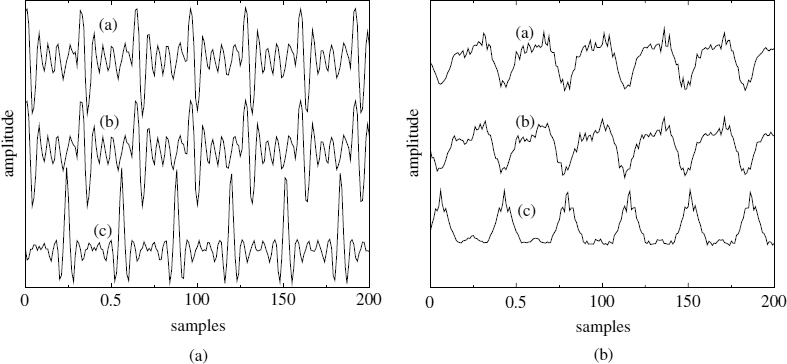
Figure 8.4 Harmonic speech synthesis: (a) original speech, (b) original harmonic phases, and (c) IMBE
An interesting feature of the IMBE coder is its simple phase model. The fundamental phase is computed as the integral of the linearly-interpolated pitch frequency, and the multiples of the fundamental phase are used as the harmonic phases. The effect of this phase model is illustrated in Figure 8.4. The coherent phase model used in IMBE concentrates the speech energy at the phase locations corresponding to the multiples of 2π of the fundamental phase. For reference, the speech waveforms synthesized using the original harmonic phases are also shown and they are very similar to the original speech waveforms.
8.4.3 Split-Band Linear Predictive Coding
The split-band linear predictive coding (SB-LPC) coder operating at 4 kb/s employs time-domain LPC filtering and uses a multi-band type of excitation signal. However the excitation signal of SB-LPC consists of only two bands, separated by a frequency marker, below which the spectrum is declared voiced and above which it is declared unvoiced. The estimation of the frequency marker of SB-LPC is different from the technique used in STC. The SB-LPC estimates a voicing decision for each harmonic band using a similar multi-band approach described in Section 8.3.1. The estimated voicing decisions are used to determine the voicing frequency marker, which has eight possible equally-spaced locations in the spectrum, the first being fully unvoiced and the last being fully voiced. One method of deciding the frequency marker is placing it at the end of the last voiced harmonic of the spectrum, i.e. all the voiced harmonics are included in the voiced band of the spectrum. A better solution for determining the frequency marker, based on a soft decision process is described in [9]. The harmonic amplitudes are estimated using equations (8.11) and (8.13) for voiced and unvoiced harmonics respectively, however the LPC residual is used instead of the speech signal. The LPC parameters are quantized and interpolated in the LSF domain. The shape of the harmonic amplitudes is vector-quantized and the gain is scalar-quantized separately.
At the receiving end, speech is synthesized with parameter interpolation based on pitch cycle waveform (PCW). First, intermediate PCWs for the current subframe are generated by interpolating the quantized model parameters of the last and current subframes. The excitation signal ei(n), 0 ≤ n < T0,i, for the ith PCW is produced as
where H is the total number of harmonics, ω0,i = 2π/T0,i and U[−π, π] denotes a random number with uniform distribution between −π and π. The start position ni for the ith PCW is given by
where n0 is the start position corresponding to the last position of the previous subframe. The interpolated pitch T0,i for the ith PCW is calculated as
where ![]() is the received pitch of the tth subframe. The interpolation factor αi is defined as
is the received pitch of the tth subframe. The interpolation factor αi is defined as
where N is the subframe size, G(·) is the received gain, and Ni is the PCW position defined by,
The starting position ![]() for the next subframe is updated as
for the next subframe is updated as
where % is the modulo operator and I is the total number of PCWs. The voicing cut-off index, Vc, is given by
The interpolated amplitude, Ae, i(l), for the lth harmonic is computed as
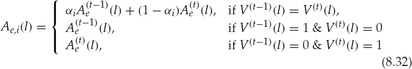
where V(·)(l) is the voicing information for the lth harmonic and 1 and 0 in the voicing comparison denote voiced and unvoiced, respectively. The LPC coefficient for the ith PCW is interpolated in the same way as, obtaining the interpolated pitch. Finally, the normalized speech signal ![]() is reconstructed by exciting the LPC synthesis filter hi(n) with the signal ei(n) in equation (8.25), as
is reconstructed by exciting the LPC synthesis filter hi(n) with the signal ei(n) in equation (8.25), as
where * is the convolution operator. In calculation of ![]() , the required memory for ei(n), n < 0, can be obtained from ei−1(n) or the excitation signal of the last subframe. The synthesized speech signal si(n) for the ith PCW is produced by compensating for the gain as
, the required memory for ei(n), n < 0, can be obtained from ei−1(n) or the excitation signal of the last subframe. The synthesized speech signal si(n) for the ith PCW is produced by compensating for the gain as
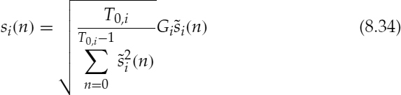
where Gi is the interpolated gain based on the relative position of the PCW in the subframe. Concatenation of each PCW in equation (8.34) forms the final speech signal.
The above description of excitation generation is based on the sinusoidal synthesis of voiced and random noise generation of unvoiced parts of the excitation. However, in practice, a DFT-based method (with the DFT size equal to the pitch period), where the unvoiced frequencies would have random phases, can be used to generate both voiced and unvoiced parts jointly [10, 11].
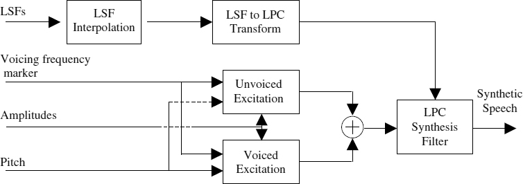
Figure 8.5 SB-LPC decoder
Table 8.1 Bit allocation of 4 kb/s SB-LPC coder for a 20 ms frame
| Parameter | Bits |
| LSFs | 23 |
| Pitch | 5 + 7 |
| Parity bit | 1 |
| Voicing | 3 + 3 |
| Gain | 5 + 5 |
| Harmonic amplitudes | 14 + 14 |
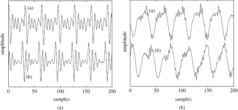
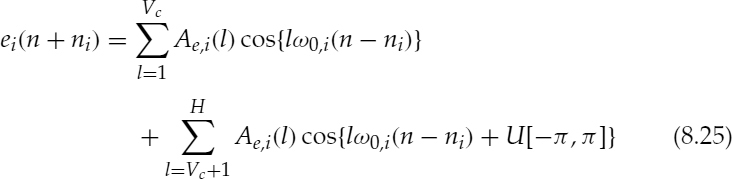
Figure 8.6 Harmonic speech synthesis: (a) original speech, and (b) SB-LPC
A block diagram of the SB-LPC decoder is shown in Figure 8.5 and the bit allocation is shown in Table 8.1. Figure 8.6 illustrates the same waveforms shown in Figure 8.4, but synthesized using the SB-LPC coder. The time-domain LPC filter adds its phase response to the coherent excitation signal of SB-LPC and disperses the energy of the excitation pulses. However the waveform shape of the synthesized speech is different from the original speech.
8.5 Summary
The fundamental sinusoidal speech analysis and synthesis techniques have been briefly discussed in this chapter. The basic sinusoidal model has been modified to reduce the number of parameters in order to adapt it for low bit-rates. At low bit-rates the frequencies of the sinusoids are restricted to be harmonics of the pitch frequency and the harmonic phases are modelled at the decoder. The concept of frequency-domain voicing is introduced to achieve a compromise between the hoarseness and buzzyness of harmonically-synthesized speech.
Three examples of low bit-rate harmonic coders have been presented: sinusoidal transform coding (STC), improved multi-band excitation (IMBE), and split-band linear predictive coding (SB-LPC). One of the main limitations of low bit-rate harmonic coders is their inability to produce adequate quality at the speech transitions.
Bibliography
[1] R. J. McAulay and T. F. Quatieri (1986) ‘Speech analysis/synthesis based on a sinusoidal representation’, in IEEE Trans. on Acoust., Speech and Signal Processing, 34(4):744–54.
[2] R. J. McAulay and T. F. Quatieri (1995) ‘Sinusoidal coding’, in Speech coding and synthesis by W. B. Kleijn and K. K. Paliwal (Eds), pp. 121–74. Amsterdam: Elsevier Science
[3] L. B. Almeida and F. M. Silva (1984) ‘Variable frequency synthesis: an improved harmonic coding scheme’, in Proc. of Int. Conf. on Acoust., Speech and Signal Processing, pp. 27.5.1–4.
[4] I. Atkinson, S. Yeldener, and A. Kondoz (1997) ‘High quality split-band LPC vocoder operating at low bit rates’, in Proc. of Int. Conf. on Acoust., Speech and Signal Processing, pp. 1559–62. May 1997. Munich
[5] J. Makhoul, R. Viswanathan, R. Schwartz, and A. W. F. Huggins (1978) ‘A mixed source excitation model for speech compression and synthesis’, in Proc. of Int. Conf. on Acoust., Speech and Signal Processing, pp. 163–6.
[6] D. Griffin and J. S. Lim (1988) ‘Multiband excitation vocoder’, in IEEE Trans. on Acoust., Speech and Signal Processing, 36(8):1223–35.
[7] A. Kondoz, (1994) Digital Speech: coding for low bit rate communication systems. New York: John Wiley & Sons Ltd
[8] DVSI (1991) INMARSAT-M Voice Codec, Version 1.7. September 1991. Digital Voice Systems Inc.
[9] I. Atkinson (1997) ‘Advanced linear predictive speech compression at 3.0 kbit/s and below’, Ph.D. thesis, CCSR, University of Surrey, UK.
[10] T. Wang, K. Koishida, V. Cuperman, A. Gersho, and J. S. Collura (2002) ‘A 1200/24000 bps coding suite based on MELP’, in Proc. of IEEE Workshop on Speech Coding, pp. 90–2.
[11] S. Villette (2001) ‘Sinusoidal speech coding for low and very low bit rate applications’, Ph.D. thesis, University of Surrey, UK.