Disk Subsystem Single Points of Failure
For years, high availability and disaster recovery have been focused on the data that resides on disk subsystems. Disk subsystems, due to the physically moving disk drives themselves, represent by far the most common failure point in computing systems. In fact, it is because of this shortcoming that RAID (redundant array of inexpensive/independent disks) came to be.
Disk Drives and RAID
Different levels of RAID exist, each with its own advantages and disadvantages. Some of the most common implementations include:
RAID 1, or mirroring. Here, a physical drive “mirrors” a second drive. Thus, for every two drives paid for and installed, only one is effectively “used” for data—for this reason, it is the most expensive of all RAID options. However, the penalty realized in terms of usable space proves to be a great benefit when it comes to the number of disk drives that may be lost while still providing access to the data. In all, half of the disk drives in a RAID 1 array may fail. Thus, RAID 1 provides the highest level of availability of all RAID options.
RAID 5, or striping data and parity. Traditionally with RAID 5, the equivalent of one drive (in a set of drives) is lost to maintain parity data, such that any single drive in the array may fail and yet the data remains intact and accessible. Thus, a set of eight 36GB drives in a RAID 5 configuration does not equal 8 times 36, or 288GB. Instead, it is 252GB, as expressed in the following formula:
(# drives * size of each drive) − (1 * size of each drive) = total usable space for data
In other words, a RAID 5 solution provides the equivalent data space of (n-1) drives. If a second drive in the array fails, though, you lose data. Exceptions exist to this in some of the newer virtual SAN array technology, though, where the equivalent of multiple drives are “lost” to maintain parity information, thereby allowing multiple drive failures within a single array.
RAID 5 is typically utilized for data volumes when the cost of additional disk drives, disk controllers, and so on is as much a consideration as raw I/O performance. As such, RAID 5 represents a good balance between cost and overall performance.
RAID 1+0, or 0+1, or 10, or striping/mirroring. Different vendors implement this differently (hence the different labels given to this RAID option), but RAID 1+0 is essentially mirroring a large group of drives and then striping data across the drives without parity. Thus, the availability features of a RAID 1 solution are realized, with the added benefit of outstanding performance as multiple disk heads are accessed concurrently. Unlike RAID 5, parity is not required because the data is protected by virtue of the one-for-one disk mirroring.
Other RAID levels exist as well, including RAID 3/5, RAID 4, and more. Refer to your hardware vendor’s RAID controller documentation for descriptions of these various implementations. Generally speaking, though, RAID 1, 5, and 1+0 tend to be used almost exclusively today.
Note
For any enterprise environment, refrain from implementing OS-based RAID for anything but your operating system drives. Sure, it works and it’s supported, but it robs the system of CPU resources at the expense of overall mySAP application or database performance. That is, operating system–based RAID adds a layer of overhead that directly impacts the performance of everything running on top of the OS. This hit on performance may be nearly negligible in some cases, but all too noticeable in others. Protecting your data and logs in these environments is therefore best left to hardware-based array controllers dedicated to the task.
Interestingly, RAID 1 evolved in a few different directions. In the case of RAID 1+0, it evolved to provide greater performance than can be realized by a RAID 1 solution. At the same time, disk subsystem vendors identified yet another permutation that would provide even greater availability and support new functionality as well—cloning, or triple-mirroring.
Cloning and Triple-Mirroring
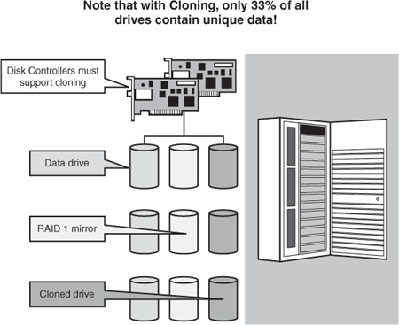
The simplest way to explain triple-mirroring is to think of a RAID 1 mirror, which consists of two drives, and to then add a third drive to maintain yet another copy of the data housed on the two other drives. Thus, a single data drive requires two additional drives to support triple-mirroring, as you see in Figure 6.9. HP refers to this as cloning; other vendors label this with their respective trademarked names as well.
Figure 6.9. Although cloning represents an excellent HA approach, it’s “expensive” in terms of the percentage of usable disk space yielded.

Cloning is a wonderful way to provide near-disaster recoverability while also presenting some other compelling capabilities. Disks may be “frozen” in time, for instance, accomplished by directing a disk controller to quit synchronizing multiple disks. In this way, a disk in a clone set can be used to keep a point-in-time backup of a database—instead of spending hours restoring from tape or performing disk copies, a physical as-is “snapshot” of the system can be created. Later, if this snapshot is needed, it may simply be presented by the disk controller back to the database server, and logs may even be applied to it (if they have been maintained somewhere where they are accessible) so that the database can roll forward to a more current point in time.
Cloning provides other benefits, too. For example, many of my customers use this third mirror to run their nightly and weekly tape backups. Doing tape backups this way can eliminate the performance hit from the actual production system (as opposed to performing online backups), as well as shrink the downtime required to perform offline backups. This last benefit is most often leveraged—instead of having to keep a database system down for hours so that all data files can be dumped to tape, cloning reduces downtime to the few minutes it takes to quiesce a database and run a script that “breaks off” the third mirror of every LUN or volume that houses a database data file.
Finally, triple-mirroring also allows for the clone set to be presented to yet another SAP server, and then accessed by end users in read-only mode. This gives end users a system upon which to execute long-running SAP queries or reports, freeing the real production system from these intense resource-consuming tasks.
All of these benefits can be realized simply by adding a third mirror to mirror sets. Of course, the storage system must support this special implementation of RAID, and the data being cloned cannot typically exist in any format other than a RAID 1 or RAID 1+0 array.
Other permutations of triple mirroring exist, too. Another one of my largest SAP/Oracle customers actually maintains three mirrors, for example. We refer to this as quadruple-cloning, for lack of a better descriptor. At midnight every evening, my customer breaks off one clone set, and uses it to support both DR and to act as a source system for refreshing other SAP systems within their SAP R/3 system landscape. Then, at noon the next day, they resynchronize this clone set with production, and break off the fourth mirror to act as a point-in-time snapshot (primarily for DR purposes). By rotating every 12 hours between breaking off and resyncing new clone sets, this customer is well positioned to address a host of HA and DR issues that might crop up and otherwise consume many hours of system restore time.
Beyond the physical disk drives that we have covered here, other common points of failure exist throughout disk subsystems. These are addressed next.
Disk Controllers
Not only are the RAID options important for disk subsystem availability—the disk controller itself is equally, if not more, critical. It is the disk controller that supports the ability to create highly available RAID arrays or clone sets in the first place. And the disk controller may often be paired, too, such that a disk controller failure can be withstood.
Many disk controllers also support data caching, where frequently or last-accessed data is retained in onboard controller-based RAM, such that subsequent accesses to the same data are performed in microseconds rather than milliseconds. The best controllers provide battery-backed cache, and configurable read/write caches, so as to assist you in both safeguarding and tuning your SAP server platforms. Be wary of using array controllers with write cache that is not battery-backed, however. Such controllers run the risk of losing or corrupting your data in the event of a power failure. That is, any writes still sitting in the write cache that have actually not been posted to the physical disk drives represent data that will be lost when the server/disk controller loses power, if not backed up by a battery on the disk controller. At one time, this was a frequent cause of corrupt and inconsistent databases. Today, more and more array controllers—even fairly inexpensive versions—support battery-backed write cache.
Unlike write caches, a controller’s read cache does not need to be protected from power outages. Why? Because if the server or controller loses the data sitting in a read cache, the controller will simply reread the data from physical disk again if it’s ever needed. Read caches only read data that already exists, so no changes are possible.
Disk Subsystem Infrastructure
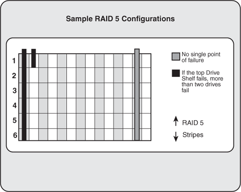
Drive shelves, individual drive cages, power bars supplying power to shelves/cages, and all of the gear used to connect the disk subsystem to the server also represent potential single points of failure. All of these are addressed by redundancy to one extent or the other. Protecting against the failure of an entire drive shelf (normally a horizontally positioned piece of gear housing 7 to 14 disk drives) is also accomplished through configuration best practices. For example, drives that are mirrored to one another (mirror pairs) should never reside in the same drive shelf—failure of the shelf would take down the entire data volume, mirror and all. Similarly, a RAID 5 array capable of surviving a single drive failure must not consist of more than one physical drive per shelf, as you see in Figure 6.10. In the real world, though, this best practice is often ignored—customers implementing RAID 5 solutions are usually doing so because they are more interested in reducing cost than completely maximizing availability.
Figure 6.10. Traditional RAID 5 configurations can only afford the loss of a single drive per array, thus limiting high-availability solutions in terms of data capacity. Fortunately, newer virtual-SAN-based products allow for multiple drive failures.

As hardware manufacturers addressed these single points of failure over the years, what started out as high-availability offerings eventually supported true disaster recoverability, as you will see next.
PMD—Physically Moving Drives
Perhaps the most basic of disaster recovery approaches I’ve ever seen involved the following process:
The customer configured all of their production database volumes for RAID 1 sets, where one drive mirrored another drive. In total, their production database data volumes resided across 16 drives (8 drives mirrored to 8 drives).
Every week, they ran through a five-minute process that I helped draft for them long ago, culminating in the physical removal of the eight drives that act as mirrors to the eight primary drives.
An operator verified that each drive was labeled as to the position that the drive held in one of the two disk subsystem drive cages (position 0 through 7, cage 0 or 1).
Meanwhile, that same day a three-week-old set of drives was brought back in from the offsite storage facility and inserted into the now-empty drive cages. The drives were re-synced to the existing drives within a matter of hours, and afterward the system was again protected by RAID 1.
The drives removed earlier were then packed and shipped offsite.
In the event that the point-in-time snapshot was ever required (for example, upon tape drive or tape media failure when attempting a restore), they obtained the drives from offsite and reinserted them into the system. The QA system could be used in this role as well if the production server failed and corrupted the database in the process of failing.
This simple approach to DR is cheap, simple, and effective. No, it’s not fully automated, and yes, it can take some time to get the disk drives back from the offsite facility. But it works for this small SAP shop, and gives them a comfort level unmatched by basic offsite tape shipping (which they still do as well).
Campus and Metropolitan Clusters
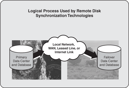
Shortcomings to approaches like PMD spawned more robust and more automated methods of maintaining offsite disk-based copies of a database. Solutions like that shown in Figure 6.11 evolved, where physical or OS-based disk sectors were copied and synchronized between sites. In this way, regardless of the database or application layers of a solution, a highly disaster-resilient solution could be employed.
Figure 6.11. Remote disk synchronization technologies like this are in wide use today, as they are typically database- and application-independent.

A good example of this kind of solution still in wide use today is HP’s Campus and Metropolitan Clusters, where a primary data center and its disk subsystem are essentially “mirrored” to a secondary data center. Such an arrangement may entail mirroring only disk subsystems, or mirroring both servers and disk subsystems. The former does little for true disaster recoverability, so the latter is a more common DR approach.
In the case of a Campus Cluster, the secondary data center is actually located at the same “site.” This might be within the same building, or perhaps a few buildings away in the case of a true campus environment. Such a cluster is built by leveraging the ability of software to write to two distinct disk subsystems, much as hardware-based RAID 1 writes to two different physical disks. The only difference here is that the physical disks are located in different disk cabinets, housed in different data centers, and a software layer like MirrorDisk/UX actually handles the data replication between the two points. To make the physical connection possible, fibre channel links are used for the data connections, and the cluster connection (or “heartbeat”) operates across a dedicated network link backed up by the IP-based public local area network used by all servers and clients. In case one of the heartbeats is lost between the sites, a cluster lock disk at each site acts as a “tie breaker,” dictating which site will own the cluster resources. All nodes must therefore be connected to both cluster lock disks. Not doing so (or losing both heartbeat connections) risks a condition referred to as split-brain syndrome, where each cluster thinks the other is down, and therefore tries to start up the services and packages related to both cluster sites. The results can be quite ugly, as you can imagine. To avoid split-brain syndrome, ensure that your heartbeat connections are routed over completely separate network infrastructures, and avoid creating cluster-disk-related single points of failure. For example, it’s important to ensure that each lock disk is maintained in its own disk subsystem; otherwise, a single point of failure results, and the cluster’s tie-breaking ability falls apart.
A Metropolitan Cluster, or MetroCluster, takes clustering to the next level by allowing for the secondary data center to reside farther away, up to 100 kilometers from the primary. The replication technology must change, however, due to the potential distances involved. This is because the standard maximum fibre channel distances are exceeded, and therefore native SCSI/RAID operations or operations managed via MirrorDisk/UX are not possible. Replication to the secondary data center requires the features of highly capable disk subsystems like EMC storage systems supporting the Symmetrix Remote Data Facility (SRDF), or HP’s SureStore XP Array with Continuous Access. To get around the distance issue, ESCON links are used, and the remote database copy is maintained in read-only mode during normal operation while each write operation is performed synchronously on disks in both locations (it is this write operation that effectively limits the distance between the data centers).
Should a failure occur at the primary data center, the secondary data center’s disk subsystem is set to read/write mode and thereby put into “production.” No cluster or quorum disks are used to manage and track the resources at each data center site. Instead, cluster arbitration servers located at a third data center site, connected to the public network, help determine which site should be running and presenting itself as the production system. In doing so, the arbitration servers play a role to avoid split-brain syndrome, much like the role played by the Campus Cluster’s dual cluster locks. Otherwise, it would be unclear to each set of nodes (site) as to which site should host the productive SAP instance. That is, without a third-party arbitrator, each site would otherwise determine that it should host production, as both sites would believe the other was down due to lack of network connectivity. Because of the multiple network links between all three sites, this arbitration server approach to avoiding split-brain syndrome is superior to the approach used by Campus Clusters.
HP Continental Cluster
Continental clusters build upon the greater distances allowed with a MetroCluster, to the point where the primary and secondary data centers can reside on different continents! Each data center maintains its own quorum, and any IP-based WAN connection suffices for data replication. Four key potential issues must be addressed prior to deploying a Continental Cluster, however:
It’s unlikely that the intercluster connection will be a dedicated line, due to the tremendous costs potentially involved. Thus, the time lag for data replication needs to be determined and addressed (or budget money earmarked for this regular expense).
Given the data replication issues, a WAN-capable Transaction Processing Monitor (TPM), a database replication tool, or some other similar utility is required to ensure that transactions are applied to the database in the correct order.
Operational issues are complicated in the event of a failover, given that failback can be difficult—Continental Clusters initially supported failover in one direction only, in fact (now, bidirectional failover is straightforward). Regardless, the SAP Technical Support Organization needs to be clear on how to eventually restore operations back to the primary data center.
Failover is not automatic; rather, the cluster itself detects a problem and then notifies the system administrator, who must verify that the cluster has indeed failed before issuing a command to recover the cluster at the other site.
In the most common implementation, asynchronous replication is used for Continental Clusters given the large distances involved in data replication. For performance reasons, I recommend that only changed data (not all data) be sent across the line, to be applied to the secondary database. Therefore, when first implemented, the secondary site must be set up manually in a data-consistent state with the primary site, such that changes are tracked and committed as they occur, one for one.
HP/Compaq Data Replication Manager (DRM)
Like MetroCluster and Continental Clusters, HP’s DRM solution is also hardware-based—it requires HP’s HSG80-based StorageWorks disk subsystems installed with version x.P firmware actually coded to support DRM. Sometimes referred to simply as a “stretch-cluster,” DRM implementations for SAP require that transactions be committed synchronously between the primary and secondary data center sites. Therefore, distance limitations of less than 100 kilometers are required (though theoretically, any distance is acceptable as long as the resulting lag in end-user response time is also acceptable). By forcing synchronous communications, the data that is written to the cache of the primary database system is written to the secondary (target) system simultaneously. To ensure SAP data integrity, the primary site waits for an “I/O completion” message from the target site before the I/O is considered successful.
Caution
Asynchronous data transfer is an option for DRM. However, given the critical role that a DR site plays in ensuring that a given mySAP system remains available even after a disaster, the risk related to never receiving the last few data packets sent by the primary system prior to failure outweighs the performance benefits inherent to asynchronous transfers—even a single missing data packet would put the DR database into an inconsistent or unknown state, making it useless for DR.
Unlike similar solutions in the marketplace today, the HP Data Replication Manager solution supports robust failover in both directions, and therefore allows each data center to effectively “back up” the other. Plus, given its huge support base of different operating systems—Tru64 UNIX, HP-UX, OpenVMS, Microsoft Windows 2000/NT, Sun Solaris, and IBM AIX—DRM is well-positioned for organizations running diverse server environments, as long as all of them leverage HSG80-based StorageWorks disk subsystems (soon to include HSV-based solutions, too).
