
The parallel port, which we’ll use as the test case for our I/O code, is really basic; in fact, I can hardly imagine a simpler interface adapter.
Although most readers probably have parallel port specifications available, I’ll summarize them here for your convenience while you’re reading the code for the module I’m going to introduce.
The parallel port, in its minimal configuration (I’m not going to deal with ECP and EPP modes) is made up of a few 8-bit ports. Data written to the output ports appears as signal levels on the output pins of the 25-pin connector, and what you read from the input ports is the current logic level at input pins.
The signal levels used in parallel communications are standard TTL levels: 0 and 5 volts, with the logic threshold at about 1.2 volts; you can count on the ports at least meeting the standard TTL LS current ratings, although most modern parallel ports do better in both current and voltage ratings.
Warning
The parallel connector is not isolated from the computer’s internal circuitry, which is useful if you want to connect logic gates directly to the port. But you have to be careful to do the wiring correctly; the parallel port is easily burned when you play with your own custom circuitry. You can choose to use plug-in parallel ports if you fear you’ll damage your motherboard.
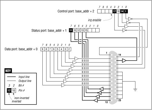
The bit specifications are outlined in Figure 8.1. You can access 12 output bits and 5 input bits, some of which are logically inverted over the course of their signal path. The only bit with no associated signal pin is bit 4 (0x10) of port 2. We’ll make use of this bit in Chapter 9.
The driver I’m going to introduce is called short (Simple Hardware Operations and Raw Tests). All it does is read and write the various 8-bit ports of the parallel interface (or other I/O device). Each device node (with a unique minor number) accesses a different port. The short driver doesn’t do anything useful; it just isolates for external use a single instruction acting on a port. If you are not used to port I/O, you can use short to get familiar with it; you can measure the time it takes to transfer data through a port or play other games.
To watch what happens on the parallel connector, I suggest that you solder a few LEDs to the output pins. Each LED should be connected in series to a 1KB resistor leading to a ground pin. If you connect an output pin to an input pin, you’ll generate your own input to be read from the input ports.
If you are going to visualize parallel data by soldering LEDs to a D-type connector, I suggest that you not use pins 9 and 10, as we’ll be connecting them together later to run the sample code shown in Chapter 9.
As far as short is concerned, /dev/short0 writes
data by means of a
tight loop that copies user data to the output port, one byte at a time:
while (count--)
    outb(*(ptr++), port);
You can run the following command to light your LEDs:
echo -n any string > /dev/short0Each LED monitors a single bit of the output port. Remember that only the last character written remains steady on the output pin long enough to be perceived by your eyes. For that reason, I suggest that you prevent automatic insertion of a trailing newline by passing the -n option to echo.
Reading is performed by a similar function, built around inb instead of outb. In order to read ``meaningful'' values from the parallel port, you need to have some hardware connected to the input pins of the connector to generate signals. If there is no signal, you’ll read an endless stream of identical bytes.
For complete I/O coverage, there are three variations of each
short device: /dev/short0 performs the loop just shown,
/dev/short0p
uses outb_p and inb_p in place of the ``fast'' functions,
and /dev/short0s uses the string instructions. There are four such
devices, from short0 to short3, and each of them accesses
one I/O port. The four ports are consecutive.
When compiled for the Alpha, which doesn’t export
insb or outsb, the device short0s behaves exactly
like short0.
Though short doesn’t perform any ``real'' hardware control, it can be an interesting test platform for timing the different instructions, and it can help you get started. Everyone interested in writing device drivers surely owns more interesting devices to play with, but the old and silly parallel port can still perform some useful tasks--I personally use it to prepare my coffee after turning on my radio in the morning.