
Electronics Elements (Detailed Discussion)
Abstract
Chapter 6 includes a detailed discussion of design elements for alarm/access control systems, system servers, workstations, advanced elements, CCTV and digital video systems, wireless digital video, security communications systems, command/control and communications (C3) consoles, console guard functions, and communications systems.
Alarm/access control systems include identification devices such as ID badges, card readers, keypads, and biometric readers. Other devices include locks, door position switches, and request to exit devices. Chapter 6 covers virtually every type of electrified door and gate lock, as well as passage portals for vehicles for both administrative (daily use) and high-security types.
The different subsystems of an integrated security system can be blended together into a single system. The system can also be interfaced with other systems to achieve advanced automated functions.
Chapter 6 covers rudimentary, advanced, and sophisticated video systems and also discusses how they can be integrated to other system elements to perform advanced alarm assessment functions.
Both analog and digital video systems are discussed in detail, including imaging devices, lenses, lighting, transmission systems (analog and digital, wired and wireless), and various analog and digital methods of video storage systems.
Video analytics include fixed algorithm analytics, artificial intelligence learning algorithms, and facial recognition algorithms.
Security communications are the root of response. Common technologies include two-way radios, cell phones, and intercoms. Intercoms can also be related to emergency phones and paging systems.
Command and communications consoles are also discussed, including situational awareness software and physical security information management systems (PSIMs).
Introduction
This chapter includes a detailed discussion of design elements for alarm/access control systems, system servers, workstations, advanced elements, CCTV and digital video systems, wireless digital video, security communications systems, command/control and communications (C3) consoles, console guard functions, and communications systems.
Alarm/Access Control Systems
The basic elements of most current alarm and access control systems are discussed in the sections that follow.
Identification Devices
Identification devices include card/key/barcode1/radio frequency identification readers, keypads, and biometric2 readers. As introduced in Chapter 5, access control systems can determine your identity by what you know, by what you have, or by who you are.
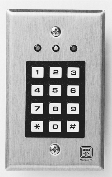
The most basic types of identification (ID) readers are keypads. Basic keypads are simple 12-digit keypads that contain the numbers 0-9 and ∗ and # signs (Fig. 6.1). The most desirable attributes of keypads are that they are simple to use and they are cheap. The most undesirable attribute of the keypad is that it is relatively easy for a bystander to read the code as it is being entered, and then you have been duplicated in the access control database (i.e., now two people know your code so now no one is sure if the person who used the code is really you). Also, the pizza delivery guy usually knows a code because there is usually someone in the organization who gives out his or her code for such things. This defeats the purpose of access control because now management has no idea who has the codes. Although shrouds for keypads are available, they are cumbersome and do not seem to be well accepted, and the pizza delivery guy still knows the code.
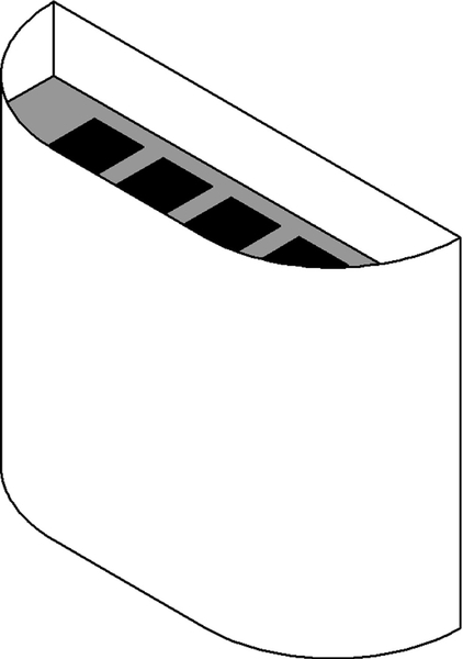
Two other variants are the so-called “ashtray” keypad, which conceals the code quite well (Fig. 6.2), and the Hirsch™ keypad, which works very well. The Hirsch keypad displays its numbers behind a flexible, transparent cover using seven-segment LED modules. Then, to confuse the guy across the room with the binoculars, it scrambles the position of the numbers so that they almost never show up in the same location on the keypad twice. This ensures that even though the guy with binoculars can see the pattern of button pressing, it will be useless because that pattern does not repeat often (Fig. 6.3). We have also found that in many organizations, there is something about the high-tech nature of the Hirsch™ keypad systems that seems to make its users more observant of the need not to give out the code to unauthorized people.

One step up the scale of sophistication from keypads are ID cards and card readers. Access control cards come in several variants, and there are a number of different card reader types to match both the card type and the environment.
Common card types include
• Wiegand wire
• Passive proximity
• Active proximity
• Implantable proximity
• Smart cards (both touch and touchless types)
Increasingly rare types include
• Barium ferrite
• Hollerith
• Rare-earth magnet
Magnetic Stripe Cards
Magnetic stripe cards (Fig. 6.4) have a magnetic band (similar to magnetic tape) laminated to the back of the card. These were invented by the banking industry to serve automatic teller machines (ATMs). Typically, there are two or three bands that are magnetized on the card. The card can contain a code (used for access control identification), the person’s name, and other useful data. Usually in access control systems, only the ID code is encoded. There are two types of magnetic stripe cards: high and low coercivity (how much magnetic energy is charged into the magnetic stripe). Bank cards are low coercivity (300 Oersted) and most early access control cards were high coercivity (2750 or 4000 Oersted). However, as clients began to complain that their bank cards failed to work after being in a wallet next to their access card, many manufacturers switched to low coercivity for access cards as well. Desirable attributes of magnetic stripe cards are that they are easy to use and inexpensive. Undesirable attributes are that they are easy to duplicate and thus not suitable for use in any secure facility.

Wiegand Cards/Keys
The Wiegand effect is named after its discoverer, John R. Wiegand. The Wiegand effect occurs when a specially made wire is moved past a magnetic field, causing it to emit a very fast magnetic pulse in response (10 μsec) to the magnetic field. Wiegand wires are placed into cards and keys in a pattern of north/south such that they create ones and zeros when read by a Wiegand card/key reader. In the early days of access control, a wiring protocol was established to accommodate Wiegand effect readers, called the Wiegand wiring scheme for card readers. Today, manufacturers refer to their proximity card readers to be wired with this Wiegand wire interface.
Barcode Cards
Barcode cards use any of several barcode schemes, the most common of which is a conventional series of lines of varying thicknesses. Barcodes are available in visible and infrared types. The visible type looks similar to the UBC barcode on food articles. Infrared barcodes are invisible to the naked eye but can be read by a barcode reader that is sensitive to infrared light. The problem is that either type can be easily read and thus duplicated; so barcodes are also not suitable for secure environments.
Barium Ferrite Cards
Barium ferrite cards are based on a magnetic material similar to that used in magnetic signs and refrigerator magnets. A pattern of ones and zeros is arranged inside the card, and because the material is essentially a permanent magnet, it is very robust. Barium ferrite card readers can be configured for insertion or swipe type. For swipe types, these are often in the form of an aluminum plate placed within a beveled surface. The user simply touches the card to the aluminum surface and the card is read. Swipe and insertion barium ferrite cards and keys are almost nonexistent today, relegated only to legacy systems. The aluminum touch panel is still common in some locales.
Hollerith
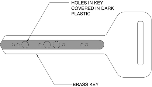
The code in Hollerith cards is based on a series of punched holes. The most common kind of Hollerith card is that which is used in hotel locks. Some Hollerith cards are configured such that their hole patterns are obscured by an infrared transparent material. One brand of Hollerith is configured into a brass key (Fig. 6.5). Hollerith cards are not commonly used in secure facilities.
Rare-Earth Magnets
An extremely rare type of access credential is the rare-earth key. The rare-earth magnets are set in a pattern of four wide by eight long and each can be positioned so that north is pointing left or right, making a pattern of ones and zeros. Such keys are very difficult to duplicate and are suitable for high-security facilities, although their cost is high because each key must be handmade.
Photo Identification Elements
Access cards grant access and identification cards provide visual evidence that the bearer is authorized to be in the area. Identification badges can have many visual attributes, including a photo of the bearer, a logo of the organization (not necessarily a wise thing), the bearer’s name, and a color scheme that may identify areas where the person is authorized. Sometimes, a color or code may designate if the bearer is a contractor or vendor.
To help verify the authenticity of the card, it is common to laminate a holographic overlay that provides a visual indication that the card has not been tampered with.
Some organizations use separate access cards and identification cards, but most have combined the two functions into a single credential.
Multi-technology Cards
As organizations grow, it is common for some employees to need to travel to multiple offices and facilities where different card technologies may be used. There are three solutions to this problem. One solution is to have the traveling employees carry a different card for each facility they visit. Another is to convert the entire organization’s access control system to a single card standard, which can be expensive. Finally, technology can come to the rescue by creating a card that contains codes that are readable by two or more access control systems. Multi-technology cards can include magnetic stripes, Wiegand, proximity, and even smart cards all in one card. Implantable chips can provide access to very high-security facilities with an assurance that the credential has not found its way into the wrong hands.
Card Readers
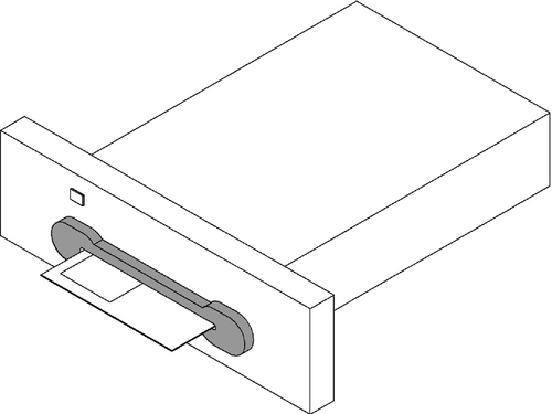
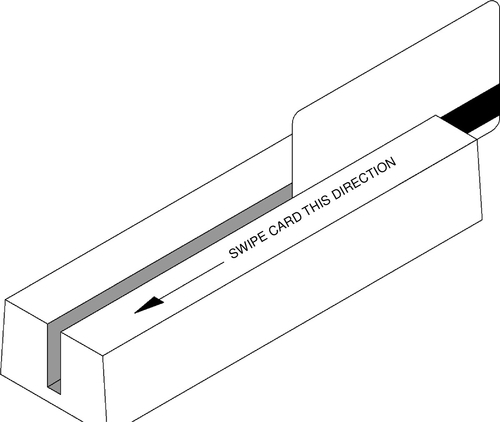
Card readers have been configured in a number of different ways. Early card readers were of the insertion type (Fig. 6.6). These were prone to getting dirty and thus reading intermittently. Swipe readers came next (Fig. 6.7). These were easier to keep clean and more reliable. These mostly eliminated the problem of chewing gum and coins being inserted and were also easy to use. However, reliability was still a problem.
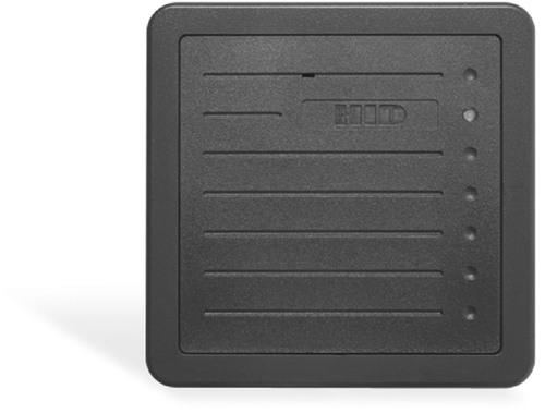
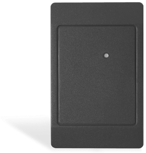
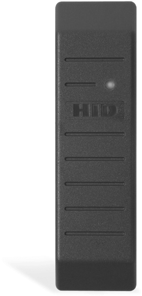
Proximity card readers date back to the early 1970s, and they continue to evolve (Fig. 6.8). Reliability issues have been virtually eliminated for all but intentional abuse. Proximity card readers have been designed for many unique environments, including normal interior walls (for mounting to single-gang electrical box) (Fig. 6.9) and door frames (mullion readers) (Fig. 6.10). There are also long-range readers for use in car parks and garages so that the user does not need to roll down the car window and be exposed to the weather (Fig. 6.11).
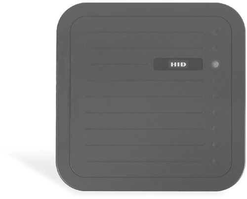
Proximity cards and readers work by passing a handshake set of radio frequency signals (traditionally in the 60- to 150-kHz range). Basically, the reader is always transmitting a low power signal through one of two antennas in the card reader. When a card comes into the radio energy field, the radio frequency energy is picked up by one of two antennas on the card and is used to charge a capacitor. When the capacitor voltage reaches a critical level, it “dumps” its energy into an integrated circuit (chip) on the card, which is programmed with a unique card number. The chip also has a radio frequency transmitter, and it transmits the unique card number through a second antenna on the card. All this occurs in milliseconds. When the card reader picks up the transmission from the card, it passes the card number to the reader input board of the access control system, where a grant/deny access decision is made based on the facility code and card number, which together make up the unique card number code, and the day and time of presentation of the card.
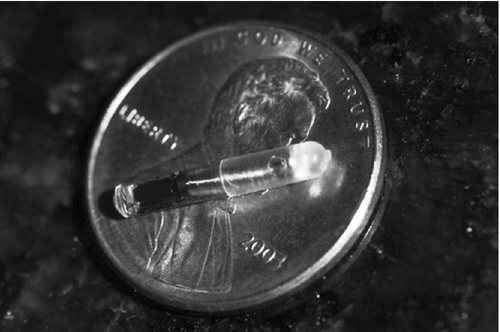
Newer proximity cards and readers use smart-card technology that can also receive, store, and process information from the card reader back to the card, allowing more complicated transactions. For example, the card can be used like a credit card to purchase food in a vending machine or gas at a gas pump. The card can store a history of transactions, such as where the user has gone and with what readers he or she has interacted. Some transactions may be unknown to the user such that it is possible to track a user’s position in a facility at any given time or for other special purposes. One exotic access control credential is the implantable chip. Only slightly larger than a grain of rice, the chip can be implanted in a user’s arm and can provide access to high-security areas. These chips have been implanted in agricultural animals and pets for many years to help track an animal’s health and locate its owner when lost. It is the closest thing to biometrics (Fig. 6.12).
TWIC Cards
The U.S. Transportation Security Agency (TSA) has implemented the Transportation Worker Identification Credential (TWIC) program. The TWIC card can be used for all personnel who require unrestricted physical or computer access to TSA-controlled facilities. TWIC credentials are used at facilities that are under the jurisdiction of the Aviation and Transportation Security Act and the Maritime Transportation Security Act. TWIC cards include a photo, biometric credential, and standard access card credentials all in a single card. TWIC positively ties the person to his or her credential and to the person’s threat assessment. The credential can then be used to allow unrestricted access to the cardholder for appropriate areas of the facility. TWIC cards will help ensure that cardholders who travel from facility to facility can be recognized with a single card.
Biometric readers come in many forms, but all share the function of identifying a person by his or her unique physical attributes. Common biometric readers include fingerprint readers, hand geometry readers, iris scanners, voice recognition systems, handwriting recognition systems, and finger blood vessel pattern recognition systems.
Other Field Devices
These include electrified locks, door position switches, request-to-exit devices, and gate operators. Electrified locks are discussed in detail in Chapter 7.
There are a nearly infinite number of types and applications of electrified locks. This is one of the areas that set the master designer apart from the journeyman. It pays to learn electrified locks exceptionally well because many codes stipulate how certain types of electrified locks can be applied. Also, each project has a unique set of security requirements that, combined with door types, directions of travel, fire exit paths, and codes, makes for an infinite combination of lock types. There are several basic types of locks.
Electrified Strikes
Electrified strikes replace the conventional door strike into which a typical door latch closes. Unlike a conventional door strike, which requires that the door latch be retracted in order for it to open, the electric strike unlocks the door by simply folding back to release the door latch as the user pulls the door open. It springs back instantly as the door latch clears the strike so that it is ready to receive the latch as the door closes again. There are many types of electric strikes, but they all operate the same way. A few electric strikes are strong enough to be considered security devices, but most should not be relied on for high-security environments. Unfortunately, most electric strikes are not rated for their strength, which makes it difficult to determine whether one should rely on it to resist a forced attack. Any strike that does not list its physical strength should be assumed to be incapable of resisting a forced attack. One of the favorable attributes of electric strikes is that they do not draw power except when they unlock. This makes them suitable for environments in which power availability is a concern.
Electrified Mortise Locks
A mortise lock is a lock that is built into a routed pocked or “mortise” in the door. These locks are very strong because the lock is sizable relative to the latch and deadbolt and the lock is effectively part of the door, so it is essentially as strong as the door. When a mortise lock is placed in either a solid-core door or a hollow metal door, it is placed into a hollow metal frame. The result is a very strong door and lock. Mortise locks are available in a variety of configurations, the most common being office and storeroom types. The office lock is equipped with only a latch bolt, and the storeroom type is equipped with both a latch bolt and a deadbolt. Electrified mortise locks are simply normal mortise locks in which the latch bolt has been attached to a solenoid within the lock body so that upon triggering the solenoid the latch bolt retracts, unlocking the door. There are a few electrified storeroom mortise locks, but most are of the office type.
Magnetic Locks
Often considered the staple of electrified locks, the magnetic lock is little more than just an electromagnet attached to a door frame, and there is an armature attached to the door. When the electromagnet is energized and the armature on the door is against the lock, the lock engages. These are typically very strong locks, usually having 800-1500 lbs of holding force. This lock is sometimes stronger than the door to which it is attached. Magnetic locks should be used with a redundant means of unlocking to ensure that a person inside the locked area can always exit. A “Push to Exit” button or crash bar that interrupts power to the magnetic lock is always advised.
Electrified Panic Hardware
Where a door is located in the path of egress, panic hardware is often used, depending on the occupancy rating. Panic hardware is required on any door where there could be a large number of people needing exit in an emergency. Panic hardware is easily identified by the push bar (formerly called a crash bar) that the users press as they push through the door. Panic hardware facilitates a single exit motion because users have only to push on the door as they are moving through it. This facilitates the rapid exit of large numbers of people because no one has to wait behind anyone else while they stop to turn a door handle. In a severe emergency such as a fire, such momentary delays can compound to cause a crush of people behind a door that is unlocked but that can become a barrier if someone has difficulty with the door handle. There are several basic types of panic hardware configurations, depending on the requirements of the door to which the panic hardware is mounted. Panic hardware is electrified by one of several methods, usually involving a solenoid that releases a latch on the door.
Specialty Locks
Most people pay little attention to doors and locks; they just use them. However, there are a remarkable number of variations of doors, frames, locks, and electrification methods. Some unusual locks have been developed for special needs (see Chapter 7).
Switches
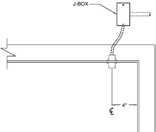
Door and gate position switches (DPS) sense if the door or gate is opened or closed. A variant of the DPS is the monitor strike, which determines if the door is not only closed but also whether a latchbolt or deadbolt is in fact engaged. The typical DPS is composed of a magnetically sensitive switch and a magnet placed close to the switch.
Typically, the switch is placed on the door frame and the magnet is placed on the door or gate. When the door or gate is opened, the switch also opens, sending a signal to the alarm system. Variants of DPSs include surface and concealed mounting versions (Figs. 6.13 and 6.14), wide- and narrow-gap sensing areas, and conventional or balanced bias types. Wide-gap DPSs were developed to prevent accidental triggering by nuisance conditions, such as when the wind blows against a sliding glass door.
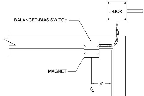
To prevent an intruder from simply placing a magnet against the DPS while opening the door, balanced-bias switches were developed that place the switch in a closely controlled magnetic field. If another magnet is brought near the switch when the door is closed, that act alone will trigger an alarm even before the door is opened.
Other types of DPSs include plunger type, Hall effect, and mercury switches. These are sometimes used in areas where it is not possible to place a magnet in the door or gate or where a device must be alarmed if it is moved. The plunger switch alerts when the object that is pushed against it is moved. These are often mechanical switches and can be unreliable for high-security applications. Hall effect switches rely on the presence of a magnetic field within a confined area to alert. They also work by moving the object. Mercury switches are sometimes placed inside an object that should not be moved in any dimension and can be made to alert to the slightest movement. These are often used with radio frequency transmitters.
Duress Switches
Duress switches are usually placed under a desk or counter to alert security if the person at the counter feels threatened. The two most common types are finger activated and footswitch activated. If the person believes he or she needs assistance, he or she can either push a shrouded button (or two buttons together to prevent false alarms) or place a toe under and lift a footswitch. Another type used in cash drawer applications is the bill trap. This type activates when the last bill in a drawer is removed, indicating a robbery.
Request-to-Exit (REX) Sensors
It is good that a security system can alert when a door is opened, but what about a DPS at a door equipped with a card reader? When a person is exiting that door legally, there must be some way to sense that the exit is not an alarm and bypass the DPS for the duration of the door opening. This is what a REX sensor does.
There are two common types of REX sensors, infrared and push switch. An infrared REX sensor is placed above the door on the secure side and constantly monitors the door handle searching for human motion. When motion is sensed in the approach area to the door, the sensor activates and thus alerts the access control electronics that the pending door opening is a legal exit, not an alarm.
The push switch type is configured either as a labeled button near the door (required in most municipalities for magnetic locks) or can be a switch that is configured into the handle of a mortise lock or the electrified panic hardware push bar. These are more intuitive.
Even when other types of REX sensors are used on magnetically locked doors, it is still important to configure a labeled “Push to Unlock” button near the door. This button should be wired both to the access control system electronics to signal a legal exit and to the lock through a timer to ensure that if the access control system electronics should fail, the user may still exit the door. It is not only embarrassing but also can be legally costly and even deadly if a user is ever trapped inside a building with no way to exit.
Door and Gate Operators
Door and gate operators are mechanical devices that automatically open and close doors and gates in response to a command. Door operators are common in public buildings and assist in the movement of large numbers of people with little effort or assist handicapped persons through the door. Gate operators are commonly used to automatically open vehicle gates in response to a command.
Door operators are often used with magnetic locks such that the access control system may both unlock and then open a door. This is common at main public and commercial building doors, and this combination is also frequently used where there is a requirement to assist the handicapped. Wherever door operators are used with magnetic locks, it is imperative to sequence the operation such that the door unlocks first and then opens. If this sequencing is not built into the design, the automatic operator may fail after a short period of time. Better door operator companies have incorporated a special circuit for this purpose, but it must be specified. I designed one of the first such interfaces for a major door operator manufacturer. Doors that are in the path of egress must be equipped with safety devices to ensure that a person can exit in an emergency with no special knowledge. This typically means that there must be a labeled push button or some other type of code-approved method of egress. Codes will always prevail on any magnetically locked door. Do not assume that a code from one city is acceptable in another. Know your codes.
Gate operators that are electrically locked must also be interfaced in order to function correctly.
Revolving Doors and Electronic Turnstiles
Revolving doors and electronic turnstiles are sometimes used to provide positive access control. That is, each person must enter and leave using an access credential, and only one person may transit the portal at a time for accountability purposes.
Revolving doors (Fig. 6.15) can be equipped with a special operator that will allow only one person at a time through a rotating (X) pane. Like door operators, revolving doors can be locked between uses, but even when unlocked, they can be controlled by the operator so that only one rotation is permitted. Early revolving door operators were sometimes problematic. However, modern operators by major manufacturers are well developed, and most work well. It is wise to coordinate directly with the manufacturer of the revolving door operator to achieve the desired functions. These may include the following:
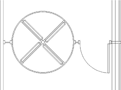
• Remote bypass from a security console
• Auto-reverse if two or more people enter on one card use
• Auto-reverse if an unauthorized person attempts to use the door at the same time as an authorized user but from the opposite side of the revolving door
• Audio alert of improper use with instructions
Such doors are also available with status alerts on alarm, on reverse, with user count, and other options.
Revolving doors for access control should be configured to the “X” rather than “+” configuration when waiting for next use.
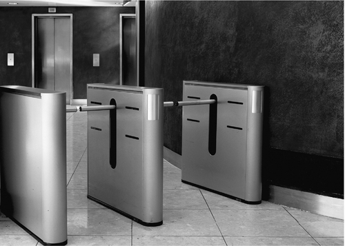
Electronic turnstiles (Fig. 6.16) are similar to the old-fashioned turnstiles used at subways and ballparks, except that the rotating member is replaced by an infrared photo beam that detects when someone passes through. There is also a type of electronic turnstile that uses paddle arms or glass wings to act as a physical barrier. These devices are designed to control access to a commercial or government building with a high degree of speed (throughput) and elegance. Electronic turnstiles must be used with an access control system that can deliver speedy card executions in order to be accepted by the users. As for revolving doors, the designer should coordinate the specifications carefully with the turnstile manufacturer.
Electronic Processing Components
Electronic processing components include reader interface boards, alarm input boards, output relay boards, and controllers. Every alarm and access control system made today uses some form of controller between the workstations/servers and the field devices (Fig. 6.17). These vary slightly from manufacturer to manufacturer, but the theme is the same. Each has three basic elements:
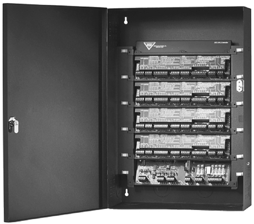
• A microprocessor with connectivity to the server and other controllers
• Memory
• Field device interface modules (reader interface boards, alarm input boards, and output relay boards)
The configuration may vary (some systems combine these elements together into one board, whereas in others they are components that can be distributed or wired together in one electrical box), but all systems use these same elements. However, that will change soon.
When I began writing this book in 2006, the concept of microcontrollers, which I had long proposed, was scoffed at by most in the industry. However, by the time this book was published in its first edition, at least one manufacturer was making small microcontrollers that control a single door, with some auxiliary inputs and outputs. At that time I said that newer generations of microcontrollers will contain their own memory and microprocessor. They will fit in a small box above the door. All that has come to pass. I also said that they will eventually incorporate a mini data switch connected by Ethernet. So far that has not happened, although I understand it to be under discussion as the second edition of this book goes to press.
I said then that this design would revolutionize the industry. The alarm and access control industry has been based for years on metal bending—that is, on the sale of hardware. This is about to become a software industry. It is part of the sea change mentioned previously.
Soon, it will be possible to connect a card reader, DPS, REX, and lock, together with an intercom outstation and a video camera, into a single small electronic smart switch that will contain its own central processing unit and memory. I have been predicting this for more than a decade, and now as the second edition goes to press, it is occurring.
Server (and Business Continuity Server)
All enterprise-class alarm and access control systems depend on servers to store and manage the master databases on which all system operations rely. Smaller systems may incorporate the server functions directly into the system’s workstation. Servers operate basically two kinds of services: system operation and archiving. On simple systems, these are both contained within a single server. On larger, more complex systems, these functions may be separated into separate boxes.
On larger systems, it is common to have a backup server that duplicates the database and functions of the primary server. This second server is usually configured to take over in the event the primary server experiences some unexpected failure or planned shutdown. Smart designers place the backup server in another building or even in another state to act as a business continuity server, not just a fail-over server. There are two basic functions on backup servers: mirrored operation and fail-over operation. Mirrored backup servers are used to maintain a constant and instantaneous backup of archived data (both alarm/access control data and video image data). Fail-over servers wait until the primary server fails, then they take control of the system instantaneously or, in simpler systems, by having the operator switch to the fail-over server. Fail-over servers should be used for system operating services and for archiving where the backup server is in the same physical area as the primary server. For true business continuity servers, the backup servers should be located off-site and all archiving should be mirrored to ensure that if a catastrophic event occurs at the primary server location, no data are lost.
Workstations
Workstations are the human interface that manage and communicate with the controllers and servers. In simple systems, one workstation may do it all—server, card programming, system programming, report printing, identification badging, and alarm monitoring. However, on enterprise-class alarm and access control systems these functions are divided among a variety of workstations.
On a system I designed for a corporate headquarters of a major petrochemical company, a single building had five workstations—one for card and system programming, one to capture pictures and program data for the photo identification system, one at the main lobby desk to monitor alarms and the electronic turnstiles access, and two for alarm monitoring in the security command center. The same system used five servers in two different buildings. All these workstations and servers resided on just one campus. This system is capable of monitoring hundreds of sites in multiple countries. There can be multiple workstations at each site, resulting in dozens to hundreds of workstations.
The point is that there is no practical limit to the number of workstations in a system. Workstations can be connected directly to the server, to the Ethernet backbone, to a controller, or to the Internet using a web browser so that a security manager can make decisions remotely while on vacation or during a weekend. Enterprise-class systems provide infinite choice.
Data Infrastructure Basics
When the user presents a card to a card reader and the card reader passes that information to a controller, a decision is made to unlock the door. That information, along with alarm detection information, is transmitted along a data infrastructure to the server, and then it is distributed to appropriate workstations. The data infrastructure is the backbone of the system. In older systems, there was a unique data infrastructure for the alarm and access control system, but most modern systems have converted to an Ethernet communications protocol. Older protocols included RS-485, Protocol A, Protocol B, 20-ma current loop, and other methods. The newer Ethernet protocol supports worldwide systems architectures that can be connected in many different ways to meet the special needs of each client, each site, and each security environment. Additionally, Ethernet protocols can also communicate CCTV and voice technologies all on a single data infrastructure. Ethernet can be easily converted to fiber optics, 802.11a/b/g/n, laser, or geostationary satellite and even on SCADA systems to facilitate unique environmental requirements where normal wired infrastructures present design challenges. It would be easy to write an entire book(s) on the subject of security system data infrastructures, and it is a difficult subject to boil down to its basics. More information on this subject is presented here and in the System Commissioning section of this book.
Interfaces to Other Building Systems
Alarm and access control systems begin to perform wonders when they are interfaced to other building systems. Typical interfaces include fire alarm systems, elevators, parking control systems, lighting control systems, signage, roll-down doors, private automatic branch exchange (PABX) systems, paging systems, water features, irrigation control systems, and even escalators. The primary purposes for interfacing alarm and access control systems to other building systems is to control access to things other than doors and gates, enhance safety or convenience to building users, automate building functions that would otherwise be handled manually or by numerous other systems, or insert a delay into the path of an intruder.
Advanced Elements
Legacy Systems Integration
One of the key challenges facing enterprise security systems designers is how to integrate the new technology into older, legacy systems. Typically, government entities and large corporations have developed their security systems in a somewhat haphazard fashion. This resulted from the fact that electronic security was initially addressed at the local level in almost all large organizations, and only later did they come to realize that there was a value to having a single standard across the entire organization. The result was that most organizations had many different types of products across various sites that were difficult to blend into a single contiguous system. To complicate this problem, the security industry has a long tradition of proprietary systems that are not based on any single standard (with the exception of CCTV systems, which had to conform to the preexisting NTSC standard). Virtually every alarm and access control system and every major security intercom system used components that could not be interchanged.
This problem was compounded by the early introduction of digital video systems that were based on proprietary compression technologies, which again ensured that the stored data could not be shared with their competitors’ products. The first piece of good news is that the entire suite of enterprise security system components connects to Ethernet data infrastructures.
The bad news is that there are three not entirely small problems:
• Older and current alarm and access control systems still use proprietary software interfaces that in most cases are not intended to link their data with other competing systems. Manufacturers still seem to hope against all logic that their clients will gleefully abandon all installations made by other manufacturers and replace them with equipment made by them.
• Different digital CCTV manufacturers have adopted varying video compression technologies, making interfacing to a single standard difficult. Some manufacturers have even modified existing compression algorithms to become proprietary to them alone.
• As security intercom manufacturers move to digital products, they are also adopting numerous different compression protocols, again making a single platform more difficult.
Now the second piece of good news: Computers are very good at operating multiple protocols together on the same platform. That means that unless the compression protocol is truly unique, it is possible to combine multiple protocols into a single operational platform.
The third piece of good news is that some of the alarm and access control system manufacturers are beginning to make uniform interfaces to create multi-system interoperability.
The fourth piece of good news is that, in almost all cases, it is not necessary to fully interface different systems together in order to get them to cooperate in truly meaningful ways. Interfacing methods are discussed in detail in Chapter 14.
Data versus Hardware Interfaces
Alarm and access control systems are often interfaced to other building systems, such as elevators and building automation systems. There are two ways to accomplish these interfaces. They can be realized either by exchanging data information or by handshaking with dry contacts between the two systems. There are advantages and disadvantages to both approaches.
Data interfaces have wonderful advantages. First, a single data interface (one little wire) can last a lifetime, no matter how many times the systems are expanded, adapted, and upgraded. Once the original data interface is connected and the software is interfaced, the systems can be adapted repeatedly to expand the quantity and functions of the interfaces.
Second, that single wire can control an empire. Once an interface is conducted on a network, it is global. It is not necessary to interface each and every site if the systems can communicate by a data interface.
Although data interfaces are wonderful, because they rely on software, they are vulnerable to software upgrades. When software is upgraded, it is not uncommon for software programmers to forget the little details of the last issue that almost nobody used. Nobody used it; it cannot be important enough to keep updated while we are under a tight schedule to meet the upgrade release date. We can pick that up in a patch later. Thus, the poor unsuspecting client eagerly awaiting his or her new software upgrade installs it and the interface does not work any more—instant software data interface vulnerability. There are indeed organizations that have had to reinstall obsolete software in order to maintain an old data interface.
Likewise, there are advantages and disadvantages to hardware interfaces. Hardware interfaces are accomplished by connecting the dry contact of a relay in one system to the input point of another system. This allows the first system to signal the second system that some condition has changed and the second system should do something about it. This simple principle is multiplied to accommodate as many individual connections as each system needs. Relays can be combined to perform logic (and, or, not, and if), and they are reliable. Once a relay interface is set up and tested, it does not matter how many times the software is updated on either system. It will always work.
The disadvantage of hardware interfaces is that they are generally site specific and they are entirely inflexible. If the system is expanded, and more interface points are needed, more relays and more inputs will be required—more expense every time there is a change or expansion. Thus, it is a trade-off. Each system requires an individual decision as to what is in the best interest of the organization.
CCTV and Digital Video Systems
Evolution of Analog Video Systems
The Bookends of Time
There was once a time when video cameras were a very rare element in security systems. Any system that had even one video camera was considered the pinnacle of high-technology security systems. Now security video cameras are available for under $100. In the old days, the ability to see outside the building was considered extraordinary. Today, cameras are used to determine if a particular person in a crowd of 50 is acting suspiciously without human intervention and then alert a security officer to that fact for further analysis. This kind of automation can be occurring across 1,000 cameras over an entire subway system, vastly increasing the value of the security organization to the city it serves.3
How Analog Video Works
Television video was invented by Philo Farnsworth, who was an employee of Thomas Edison. This inventive genius worked out that if you could control the movement of a directed electronic beam against a phosphorus surface affixed to glass within a vacuum tube, you could “paint” the phosphor with a luminous line. Vary the intensity of the beam and you can make it glow brighter and darker. Cause the beam to return to its origin and shift it down a bit over and over again and you can paint a picture on the phosphorus screen. Carefully select the phosphor so that it glows for exactly the time it takes to write one complete frame and time that to be slightly faster than the persistence of the sensitivity of the human retina and you have moving images. Television—what a concept!
The earliest security video systems hardly qualified to fit the term, having only one or two tube-type (black-and-white Vidicon™) cameras, some coaxial cable, and one or two black-and-white video monitors. Vidicon’s™ tubes and monitors required annual replacement. A huge advance in sophistication occurred when RCA invented the sequential video switcher. This handy box connected up to 16 video cameras and displayed them on two video monitors. One sequenced through all the cameras, and the second displayed one’s favorite camera view.
The Branch
Then video evolution took a branch that still continues today. On one branch was the development of a device called a “quad.” This device displayed four video cameras on a single screen and recorded them all on a single tape. On the other branch was an extension of the old sequencer, the video matrix switch. The video switch allowed the connection of many cameras (as few as 16 and as many as 64 in the early days) and could display them on up to four (or eight) video monitors. A keyboard gave the user the ability to program any camera to any monitor and could also sequence cameras to one or more monitors.
Videotape
It was at approximately this time that videotape recorders became useful for security projects. Prior to that, videotape recorders used reel-to-reel tape, with early recorders using 2-in. tape to record only 1 hour of video, and the recorders were the size of a small chest of drawers. Recorders did not become practical for any security application until RCA invented the enclosed 3/4-in. U-Matic videotape cartridge. The U-Matic tape recorder was the size of a piece of luggage but would record up to 2 hours. Soon after, Phillips invented the VHS tape recorder and the U-Matic was history. The VHS tape recorder was small and could record up to 6 hours of video. Then in the early 1990s, a company called Robot introduced a VHS recorder that was able to record up to 24 hours in combination with a totally new device, the video multiplexer.
The major problem was that at that time it was not common to break video images down, which stream at a rate of 30 frames per second, to a series of individual frames at a rate of 4 frames per second.4 Such a device would have to be able to store one image from each camera and discard the next three.
The multiplexer was specifically made to work with the new 24-hour recorder and vice versa. What was truly unique about this new pair was that it worked in a totally new way to achieve the remarkable result of 24-hour recording. A Robot researcher determined that although the VHS recorder could not record a continuous stream of video any slower than 6 hours, it could nonetheless record a huge number of individual frames of video if they were sequenced to the recorder in individual images. This approach resulted in its ability to record almost exactly two frames per second for 16 cameras. VHS recorders were designed to record a single stream of video that fed at a rate of 30 frames per second. The new multiplexer sampled a frame from each camera every half second and fed that frame as a still image to the video recorder. Thus, the new 24-hour VHS recorder stored one frame from each camera in sequence until all were recorded and then began again with the first camera. The new multiplexer passed a single frame of video from each of 16 cameras in sequence to the video recorder and then started all over again. In order to do this, the multiplexer had to do something completely new. It converted the analog scanned video into a series of digitized single frames. It was then possible to store digital frames individually on tape moving much slower than one could store an analog frame. At the time, the digitization of video was a footnote to the achievement of the multiplexer. Hardly anyone took notice. However, a few of us in the industry took note and began predicting the future. I began talking about the coming digital revolution as early as 1993.
How Digital Video Differs from Analog
Capturing and Displaying Analog Video
Analog video is created in a video camera by scanning an electron beam across a phosphor. The beam intensity is determined by the amount of light on each small area of the phosphor, which itself responds to the light being focused on it by a lens. That beam is then transmitted to a recording, switching, or display device. Analog switchers simply make a connection between devices by closing a relay dry contact. Recorders simply record the voltage changes of the electron beam onto tape, and display devices convert the voltage back into an electron beam and aim it at another phosphorus surface, which is the display monitor that is viewed.
Capturing and Displaying Digital Video
Digital video images are captured entirely differently. Light is focused by a lens onto a digital imager. This is an integrated circuit in which the “chip” is exposed rather than covered by the plastic body of the chip, as in a normal integrated circuit. It is a little known fact that virtually all integrated circuits respond to light. Early electronic programmable read-only memory chips were in fact erased of their programming by “flashing” them with light. This phenomenon was utilized to make an integrated circuit that comprised hundreds of thousands (today millions) of individual light-sensitive chips. When light was focused on this chip, it responded by creating a different voltage in each individual picture element (pixel) in direct proportion to the amount of light striking that particular element. A matrix was formed from the output voltages of each row and column of chips, and this lattice was then scanned to replicate the voltage of a conventional tube-type video imager. The result was the world’s first digital imager. Video can be displayed in much the same way as it is gathered. The most common technologies today are liquid crystal displays (LCD) and plasma displays for directly viewed displays and digital light processor (DLP) devices for projected video. All of these are variations of the same basic concept. A semitransparent color pixel (blue, green, red) is arrayed in front of an illuminator. The video image is fed to the display and the pixels do their job, displaying the video images. LCD displays have become the de facto standard for smaller displays, and plasma and LCD displays are both common for large screens. DLP projectors accommodate most displays over 60 in. diagonal, except for video walls, which are composed by grouping arrays of LCD, plasma, or projected video box displays.
Archiving Analog and Digital Video
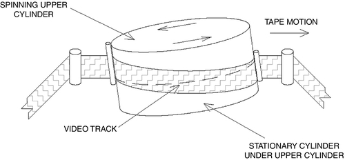
Analog video is transmitted as a fluctuating voltage with codes embedded for color, hue, and gamma. This fluctuating voltage is processed and fed to a recording head. The basic analog recording head for video works on the same principle as an analog audiotape recorder; that is, a current is fed to a specially formed electromagnet, which is formed to present a smooth surface to the tape that is being swept across the head by a pair of rotating reels. The electromagnet has a very tiny gap, across which a magnetic flux is developed in response to the fluctuating current. As the tape is rolled across the tiny gap in the recording head, the tape is magnetized in direct proportion to the current in the electromagnetic head. To play the tape back, the same tape is moved past another playback head, and the magnetic signals recorded on the tape are converted back to electrical currents, corresponding to the originally recorded signal. Videotape differs from audiotape in that the heads are slightly tilted and spun in order to record a series of diagonal stripes, each corresponding to a field of a video frame (Fig. 6.18). There are two fields for each video frame, and these are interlaced such that the first field records or displays 525 stripes of video. The beam is then shifted down to an area between the first and second stripes of the first field, and then the process is repeated for the second field of 525 stripes. When both fields are displayed together, the result is that the two fields are combined together to form a single video frame. Two fields are used because by painting the entire screen twice, and by shifting the second field slightly down from the first field so that its lines lie in between the lines on the first field, the image is of higher resolution than that of just one field and they are interlaced so that the eye does not catch the time difference from the first stripe at the top of the screen to the last stripe at the bottom.
Digital video is transmitted instead by a string of data packets. Each packet is composed of ones and zeros in a designated format. The packet has a header, footer, data, and, sometimes, encryption.5 The header has the packet address (where it comes from and where it is going, what kind of data are in the packet, how much data are in the packet, the camera identifier, date and time, and other information). The footer has information that closes the packet so that the destination device knows it has received the whole packet. Each packet of video is stored on digital disk or digital tape, and the video can be retrieved based on its time code, camera number, the alarm condition that the video is recording, or any other criteria that may have been stored in the header.
Digital Transmission Systems
Digital video packets are transmitted in either of two basic protocols: Transport Control Protocol (TCP) or User Datagram Protocol (UDP)/RDP. TCP (Transport Control Protocol) is a one-to-one communication relationship—one sending device and one receiving device. Well, that is not entirely true. TCP packets can in fact be broadcast to many destination addresses, but it requires opening an individual one-to-one session for each destination device. Where many cameras and several monitoring stations are involved, this can consume so much of the network’s resources that the entire system can freeze from data overload. For these situations, the network designer selects UDP or RDP protocols.
Digital Basics
One cannot really understand digital video without understanding digital systems. In order to understand digital systems, one must understand the TCP/Internet Protocol (IP), on which all digital video systems are based. Protocols are the basic language and culture of digital systems. In the beginning, there were numerous noncompeting digital protocols and languages. Each was developed by scientists and engineers for a specific purpose and application. There were two challenges: how to get computers to talk the same language regardless of the operating system or program language, and how to get the signals from here to there in the physical world. These were separate problems, but both had to be solved in order for networks to work at all. Basically, the early data communications solutions broke down into methods that were specific to either military or academia. In fact, the military funded most early digital communications efforts, and academia began working on the problem for the military (the beginning of a long and prosperous funding relationship for academia). Soon after the first viable computer was built, at which time there existed only several computers in several universities and military research agencies, the idea of networking these computers occurred to the users. The Applied Research Programs Agency (ARPA; a branch of the U.S. military) funded a program to develop a network that would network the various computers together. ARPA-NET was born. Now, early in the development of any new technology, there are competing ideas that are developed to solve the unique problems of the organization that it serves. Some of these turn out to be really good ideas, but most do not. They might have gotten the job done for the specific application, but networking requires a simple, robust way of getting many different computers to exchange communications through a common language. It is necessary to make sure that the communication has actually occurred and that only the intended recipients get the message. There were many challenges. Just getting signals across the nation was a major task because only telephone lines existed to get the job done. ARPA-NET did just that, along with the development of the digital modem, which converted digital pulses into audio tones and then reassembled the tones back to data at the receiving end. ARPA-NET later evolved into the World Wide Web.6 At the same time that ARPA-NET was evolving into the World Wide Web, other scientists were struggling with how to get the signals from here to there in the physical world. Basically, three ways evolved. The first worked for point-to-point communications, connecting any two computers together, and this involved the invention of modems. The second and third ways involved connecting many computers together in a true network and two approaches developed, from which a truly rich tapestry of interconnections has evolved. The first is a ring network and the second is a line, hub, and tree family of networks. Both approaches functioned by connecting individual digital devices (nodes) onto a network. In early ring networks, a token (thus the term token ring) was passed from node to node like a baton in a relay race. Whoever has the token can talk. Everybody else gets ready to listen.7 When the node with the token is done dumping data on the ring, the token is passed on to the next node on the ring. It examines the data to determine if it is the addressee and, if it is, it downloads the data; otherwise, it passes it on to the next node, after adding its own message to the data. Token rings are robust because there can be no collisions of data messages on the network. They work well as long as the data being sent is relatively small. When the data movement becomes large, token rings break down under the weight of all the data, and the ring moves slower and slower as each node processes what it does not want and adds its own to the message. Remember, however, there is never a collision because only one node can be on the ring at any given time.
The other method that was developed was collision based. The earliest of these were line communications systems in which each node attached to a common communications line, such as a coaxial wire. Any node could get on the line at any time and transmit, and every node was in listen mode if it was not transmitting. The great idea of this approach was that nodes did not have to wait for a token to be passed to them in order to listen; they were pretty much always listening. This greatly reduced total traffic on the network. The problem was that if two nodes tried to transmit at the same time, there was a collision and no other node could hear because the data turned into noise, like a room full of people arguing where no one can be understood. This approach required a protocol that could handle the collisions. Two methods were used to handle the collisions. The first was that the single long data streams of token rings were broken down into smaller individual packets of data that would be transmitted and then reassembled at the receiving end. The second was an embedded code that told the receiving node that it had in fact received all the packets of the message to which the packet belonged. So if a message consisted of 25 packets and only 23 were received, the receiving node would call out on the network for the two missing packets, and the sending node would resend only those two packets. When all the packets of the message were received, the receiving node would call back to the sending node with a message that all packets had been received and that communication was over. This approach took some working out for several years until the highly robust and reliable TCP/IP protocol suite was developed and refined. Along the way, the network protocols developed virtual local area networks (VLANs), virtual private network (VPN) subnets, and even so-called supernets. In theory, there is no practical limit to the number of nodes that can be connected to a TCP/IP network. Today, we are working on IP version 6 (IPv6), which has a potential limit in the trillions of connected nodes, all communicating together on a common backbone, the Internet. After the pure line network came hub or star networks. The hub was simply a line network in which there was a single central point to which all the nodes connected. That device was called a hub. Hubs work well for a few nodes, for example, up to 256 nodes, depending on traffic. However, as the number of nodes increases, so does the number of collisions of data packets. A collision is when two data devices try to send a data packet on the same line at the same time. It is a funny thing about physics: It always works. For anyone who wondered if the data world somehow is more mysterious than the physical world, collisions prove the fact that the same rules work everywhere. As in any other kind of collision, things get broken. So when a data collision occurs, neither packet can get through intact. Neither packet gets to its destination; both must be sent again until each one is on the data bus alone to find its destination. Until then, both data devices may send the same packet repeatedly until one of them makes it, and then the other packet will have no competition for the data bus and it can find its destination too. Thus, with increasing collisions comes increasing traffic. In fact, there is a critical mass beyond which there are more requests to resend information than there can be new information being sent. That is a system crash.
This problem can be resolved by analyzing the data traffic on a typical network, which will almost always prove that most traffic across the network does not in fact have to be sent across the entire network but only to nodes8 that are logically (and often physically) grouped together—for example, nodes within a specific building or a campus. By limiting that kind of traffic to just the nodes within that group, and making exceptions for traffic that specifically asks to go outside the group, we can vastly reduce the amount of traffic, again making more overall traffic a reality. The device that does this is a data switcher. The data switcher is capable of switching traffic only to the devices to which the data is being addressed, based on a logical group so that most traffic is unencumbered by the other traffic that does not need to go out to the overall network. Fewer connections, fewer collisions, more traffic. So a switch is a device that determines where data goes.9 As many nodes connect together using switches, they form a local area network (LAN).
There is a higher level of restriction than that of switches. Routers can do the same job for entire buildings and a campus, making sure that traffic that does not really need to go from Chicago to New York stays on the Chicago campus. Routers connect individual LANs into wide area networks (WANs). Routers can even be used to create logical subnetworks (subnets) that can ensure that the security system is inaccessible on the company’s administrative network. A subnet is essentially a VLAN (a network within a network). Routers are also capable of creating a VPN, which is essentially a tunnel within a network or Internet connection that shields the session from prying eyes on the network or Internet. This is useful when a remote user is compelled to use the Internet for private company work. Think of it as a wormhole through which you could operate your laptop at home as though you were actually connected by hardware directly to your network at work. This is different than an Internet session that can easily be hacked. A VPN shields the communication between your laptop and your network within a force field of encryption. VLANs and VPNs are used to facilitate communications between segments of an enterprise security system across a corporation’s WAN or across the Internet.
Routers also route data not just based on its intended address but also based on what kind of data it is. For example, certain types of data can be “zipped right past” other switches and ports on the network if those ports have no need to see that kind of data. This is an important principle for security systems that we will understand better as we begin to discuss unicast and multicast data types later. Digital video systems sometimes use multicast-type data in order to conserve the bandwidth of the LAN. However, many devices cannot coexist with multicast data, so a router is used to ensure that those devices never see the multicast data.
Remember the ring? Did you think it was dead with line and tree networks? Oh, not so! One critical element of enterprise security systems is that they need to be reliable, redundant, and robust. By connecting a line of switches together and closing the two ends of the line, we get a loop or ring again. By adroit switch programming, we can configure the system such that it communicates not just one way to home but both ways around the loop. Again by adroit switch and router programming, we can configure the loop so that if one switch or node is lost, for example, if the loop is cut, the others will communicate left and right from the cut in the loop so that only the node and not the entire tree is lost in the pruning. Routers and switches can be programmed so that the loop heals itself and reports the lost node so repairs can be made in a timely manner. I recommend designing all enterprise-class security systems as a dual-redundant self-healing loop wherever possible.
Wireless Digital Video
Conduit and wiring is expensive. It can represent up to 70% or more of the total cost of outdoor systems. However, conventional wisdom is that wired reliability is not possible in wireless systems. That is not so. If the goal is to replicate a dual-redundant self-healing wired loop, it is indeed possible and practical to do so at lower cost compared to that of conduit and wire. However, there are a few problems, which will be discussed here.
Wireless Approaches and Frequencies
There are usually many ways to do things, and that is certainly true for wireless video. Following is a list of the most common ways of transmitting video wirelessly:
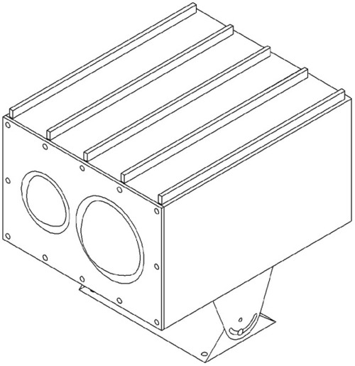
• Laser: Although becoming more difficult to find, laser transmitters and receivers have several advantages over other methods. The system typically comprises a laser transmitter and receiver pair, with optical lenses and weatherproof enclosures. The system is normally one-directional, so it is not well suited for pan/tilt/zoom cameras that need control signals. Laser video transmitters are immune to radio frequency noise but are affected by heavy fog or rain or blowing objects (Fig. 6.19).
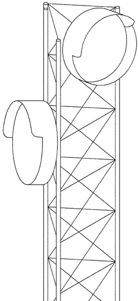
• Microwave: Microwave wireless systems can transmit either analog signals or data. Unlike laser and many radio systems, virtually all microwave systems require a license. Properly applied microwave systems can transport signals considerable distances, typically up to 20 miles. Microwave systems can be bidirectional and require careful, permanent placement. Although temporary systems exist, those are usually deployed by the military, not for civilian use. Microwave systems are subject to a variety of interference factors, including fog, rain, lightning, and other microwave signals. However, when fiber is not practical and radio frequencies are a potential problem due to other radio frequency interference, microwave is often a sure thing (Fig. 6.20).
• Radio: Most wireless video today is transmitted over radio waves. These can be either analog or digital. Radio-based wireless systems are of two types, licensed and unlicensed. It is often more reliable to use licensed systems for permanent installations because interference is less likely.
• Frequencies: The following are common frequencies for radio video transmitters/receivers:
900 MHz (FM TV–analog and digital)
1.2 GHz (FM TV–analog)
2.4 GHz (FM TV–analog and 802.11 digital)
4.9 GHz (public safety band)
5.0-5.8 GHz (802.11 digital)
10-24 GHz (digital)
Analog
There are very few analog transmitters and receivers available today. Most of them are in the UHF frequency band. Analog transmitter/receiver pairs suffer from radio frequency noise and environmental conditions more so than do digital systems, and their signal becomes weaker with distance, affecting their image quality. Analog radio systems directly transmit the analog PAL/NTSC video signal over the air. Most of these systems require a license if their power is more than 50 MW.
NTSC is a transmission standard named after the National Television Standards Committee, which approved it for use in the United States. It transmits a scan rate of 525 at 60 Hz and uses a video bandwidth of 4.2 MHz and an audio carrier of 4.5 MHz.
PAL stands for phase-alternating line. PAL is used in many countries throughout Europe, Africa, the Middle East, South and Southeast Asia, and Asia. PAL signals scan 625 lines at 50 Hz. The video bandwidth is 5.0 MHz and the audio carrier is 5.5 MHz. Some countries use a modified PAL standard called PAL N or PAL M. PAL N has a video bandwidth of 4.2 MHz and audio carrier of 4.5 MHz. PAL M has a scan rate of 525 lines at 50 Hz, video bandwidth of 4.2 MHz, and audio carrier of 4.5 MHz.
Analog frequencies were shown previously as FM TV (see the list above).
Digital
Digital radio frequency systems transmit IP (TCP/IP or UDP/IP) signals over the air. Typically, to transmit video, either the video signal is sourced directly from an IP-enabled video camera, or an analog video signal (PAL/NTSC format) is converted to UDP/IP through a video codec.
TCP/UDP
The main difference between TCP/IP and UDP/IP is that, although both are IP, TCP is a method for ensuring that every packet reaches its destination. When one does not, the destination computer makes a request to the transmitting computer to resend the missing packet. This results in more traffic. For data such as video or audio, which are dynamic and constantly changing, there is no point to going back for a packet because the image will already have been displayed or the audio will have been heard. Thus, UDP/IP is used. UDP is a connectionless protocol that, like TCP, runs on top of IP networks. Unlike TCP/IP, UDP/IP provides very few error recovery services, offering instead a direct way to send and receive data over an IP network. It is used primarily for broadcasting video and audio over a network.
Frequencies
Common digital radio frequencies are 2.4, 5.0, 5.8, and 10-24 GHz. Some of these frequencies are unlicensed and others require a license. Generally, 802.11a/b/g/i does not require a license, whereas other protocols do.
Latency Problems
Digital signals insert circuit delays, called latency. Latency is normally measured in milliseconds (msec), microseconds (μsec), or nanoseconds (nsec). Cabled wire inserts zero millisecond latency. High-quality digital switch latency is measured in the microsecond range. The very best switches measure latency in nanoseconds. Latency becomes a significant problem above 150 msec. You should strive to design systems that have latency under 50 msec. Long latency times have three potential effects: First, you are not seeing the video in real time, but instead you are seeing a delay of the actual image. Second, you are not controlling a pan/tilt/zoom camera in real time. This is a major problem. Imagine trying to pan/tilt/zoom a camera to look at a license plate in a parking lot. Now imagine that each time you adjust its position, it overshoots its target because you are looking at the image later than the camera is sending it. This requires a constant adjustment until you can finally, and with much frustration, target the license plate. Following a moving target is utterly hopeless. Last, very long latencies (> 1 sec) can on many systems cause the TCP/IP processing process to lose track of packets, resulting in the sending of many duplicate video packets or the loss of video packets. The loss of packets results in very bad or totally useless video, and the sending of additional packets can result in even slower (possibly useless) transmission that is so full of duplicate packets that no entire image can be received in a timely fashion. This is especially true of satellite transmissions. Low latency is good. The best digital wireless systems insert less than 1 msec per node. Some common system design approaches can inject up to 35 msec per node.
Satellite
Video can also be sent via satellite. There are two common methods.
Satellite Dish
Satellite dish transmission uses either a fixed or a portable satellite dish to uplink and downlink to a geosynchronous satellite. In the fall of 1945, a Royal Air Force electronics officer and member of the British Interplanetary Society, Arthur C. Clarke [the famed author of 2001: A Space Odyssey (1968)], wrote a short article positing that if a satellite’s orbit positioned directly over the equator could be configured such that it rotated at exactly the same speed as the rotation of the earth, then it would appear to “hang” motionless in orbit above a fixed position over the earth. This would allow for continuous transmissions to and from the satellite. Previous early communications satellites (Echo, Telstar, Relay, and Syncom) were positioned in low Earth orbits and could not be used for more than 20 minutes for each orbit.
Satellite video is fraught with four major problems: precise positioning, weather interference, latency delays exceeding 240 msec, and the expense of a fixed IP address on a satellite dish. The time to set up precise dish positioning can be up to one-half hour, depending on skills (some people never get it). We have seen satellite latency of up to 2500 msec. That kind of latency is almost impossible to deal with.
Satellite Phone
Satellite phones can also be used to transmit video. Unlike satellite dishes, no precise positioning is required. Simply turn on the radio, connect the video camera, establish the communication, and send. Satellite phones are very expensive, as is their satellite time, but for reporters in the field and offshore oil platforms, they make a great backup to satellite dish communications.
Latency Problems
All satellite communications insert very high latency, typically more than 240 msec. This is useless for pan/tilt/zoom use, and the insert delay makes voice communications tricky. However, if you cannot get communications there any other way, it is a real blessing. For unmanned offshore oil platforms, when connected to an alarm system, the video can confirm that a fishing vessel has moored itself out 100 miles from shore and that a break-in on the platform is occurring. Combined with voice communications, those intruders can be ordered off the platform in virtual real time with an indication that the vessel number has been recorded. During high security levels, the video system allows for a virtual “guard tour” of the platform, without the need to dispatch a helicopter at a cost of thousands of dollars for each sortie.
Wireless Architectures
There are three basic wireless architectures, and they are an analog of the wired networks.
Point-to-Point
Point-to-point wireless networks are composed of two nodes, and they communicate wirelessly between the two. It is analogous to a modem connection. Wireless point-to-point connections require a line-of-sight signal or a good reflected signal.
Point–to–Multipoint
Point-to-multipoint connections are networks in which a single wireless node makes connection to several or many other wireless nodes. The single wireless node serves all the others, and all of them communicate to each other through the same single node. This is analogous to a hub or switch or router connection. Wireless point-to-multipoint connections also require line-of-sight signals or absolutely reliable reflected signals.
Wireless Mesh
Wireless mesh systems are like the Internet. That is, each node connects onto the matrix of the mesh and finds as many connections as it can. It selects a primary connection based perhaps on best signal strength or rules set for the least number of nodes between the source and destination node. If the node cannot talk directly to the destination node, then that signal will “hop” through other nodes until it finds the destination node. A wireless mesh is like the Internet. You may not know how you got to a server in Europe, but you sure can see the web page. Wireless meshes can let signals hop several times, so even if there is no line-of-sight connection available, you can almost certainly hop around that oil tank, tree, or building by jumping across several other nodes that do have line-of-sight connections to each other. A well-designed wireless mesh network will automatically and continuously search for the best available connection or shortest available path for each and every node from its source to its destination. It will do this every time, all the time, making sure that you always have a good, solid signal.
Full-Duplex Wireless Mesh
Old radio-heads like me know that there are two ways of talking over the air: half-duplex and full-duplex. The difference is critical for digital video systems, and if the reader learns anything about wireless systems in the book, this is the thing to understand. In half-duplex systems, each node (transceiver) can either listen or talk but cannot do both at the same time. So when it is talking, it is not listening. When it is listening, it cannot talk. For a digital video system, that means that the bandwidth of the transceiver is effectively cut in half, not because it has in fact less bandwidth but because it is communicating bidirectionally only half the time. For a 54-GHz system, that means that it starts out of the box as a 27-GHz system. Subtract network overhead and encryption and you are left with approximately 22 or 23 GHz less available bandwidth. OK, you say, I can live with 22 GHz. However, if you understand that the purpose of wireless mesh networks is to use the mesh to retransmit video from node to node, it takes on new meaning. That loss of half of the bandwidth occurs with each retransmission. From the first node to the second, bandwidth is 22 GHz minus the video signal (e.g., 2 GHz), leaving 20 GHz. From the second node to the third, it is halved again from 20 to 10 GHz, and now we subtract the second video camera’s signal load, too. That is another 2 GHz, leaving only 8 GHz. There is not enough bandwidth left to safely add a third camera because we need to reserve at least 6 GHz of overhead for communication snafus. We are effectively out of bandwidth after only two camera nodes.
On the other hand, full-duplex wireless nodes communicate both directions (transmit and receive) all the time. That is because a full-duplex wireless mesh system uses two radios in each node (one transmitter and one receiver). By careful antenna selection, we can transmit and receive continuously at each wireless node. Considering our example again, we can communicate digital video effectively across up to 10 nodes, assuming a 2-GHz drop for each camera. (I use a standard of four hops). Another trick is antenna selection. There are basically two types of antennas for all radio systems: directional and omnidirectional. An omnidirectional antenna transmits or receives in a pattern like an apple. There is a slight pinch at the top and bottom of the pattern, but the rest of the radiation pattern is spherical, at least in the horizontal plane. Directional antennas narrow their “view” by restricting the view that its designer does not want. By “pinching” the part of the spherical radiation pattern that is unwanted, the part that is desired is lengthened, sometimes considerably. This creates “gain.” Useful signals can be derived from either a line-of-sight connection or a single reflected signal. However, that reflected signal can be a problem if the receiver can see both the original and the reflected signal. Reflected signals arrive later than line-of-sight signals because they are traveling a longer distance from source to destination. All antennas suffer from a phenomenon called multipath. Multipath signals are signals that originate from the transmitting source but from at least two sources, at least one of which may be a reflected signal. There is another type of antenna that is little known (at least until now), called a multi-phased omnidirectional antenna.
Video Analytics
Video analytics is a technology that processes a digital video signal using a special algorithm in order to perform a security related function. There are three common types of video analytics:
- Artificial intelligence learning algorithms
- Facial recognition systems
The first two of these both try to achieve the same result. That is, they try to determine if an unwanted or suspicious behavior is occurring in the field of view of a video camera and the algorithm notifies the console operator of the finding. However, each takes a dramatically different route to get to its result.
Fixed algorithm analytics use an algorithm that is designed to perform a specific task and look for a specific behavior. For example, common behaviors that fixed algorithm analytics look for include:
- Moving in the wrong direction down a corridor
- Leaving an article
- Picking up an article
- Loitering
- Floating face down in a swimming pool
Each fixed algorithm looks for a very specific behavior. The client must pay for each individual algorithm for each individual video camera in most cases.
Artificial intelligence learning algorithms operate entirely differently. Learning algorithm systems begin as a blank slate. They arrive completely dumb. After connecting to a given camera for several weeks, they begin to issue alerts and alarms. During that time period the system is learning what is normal for that camera’s image during the day, night, weekday, weekend, and hour by hour. After several weeks, the system begins to issue alerts and alarms on behavior in the screen that it has not seen before or that is not consistent with what it has seen during that time period for that day of week.
An example illustrates the usefulness of this approach. In one early installation at a major international airport that was intended to spot children climbing on a baggage carousel, the system alerted on a man who picked up a small bag from the carousel and placed it inside an empty larger bag. The man was intercepted and interrogated only to discover that the luggage inside his did not belong to him and that he was part of a ring that came to the airport regularly to steal baggage in this way. The airport had no idea this was even occurring, so there was no way they could have purchased a fixed behavior algorithm for this, even if such existed (which it did not). This approach to video analytics is most useful.
The third type of analytic is facial recognition. Facial recognition systems can be used for access control or to help identify friend or foe. Facial recognition systems can also be used to further an investigation.
Typical facial recognition systems match points on a face with a sample stored in a database. If the face does not match a record, it will try to create a new record from the best image available of that person. These are capable of making real-time matches of one image against many. The latest version of facial recognition systems constructs 3D maps of faces in real-time and compares those to a truly vast database. One manufacturer claims to be able to match individuals in real-time against a country-sized database of images (millions of records).
Traditional facial recognition systems require well-lit scenes and fairly static backgrounds. The latest versions are reported to work under fair to poor lighting and with dynamic backgrounds.
Lenses and Lighting
Lenses are to video what loudspeakers are to audio systems. Just as there is a dramatic difference in the quality of audio depending on the quality of the loudspeaker playing the music, so also the quality of lenses directly determines the quality of the video image. For many years, security installers used to place cheap plastic lenses on otherwise good video cameras in order to present a price advantage against their competition. The result was very poor and sometimes virtually useless video images. With the introduction of mega-pixel video cameras as expectations of better quality images increased, many users were very disappointed to see poor images from very expensive cameras when the installers fitted them with standard quality lenses.
It is very important to use only good lenses on every video camera. And it is especially important to use only mega-pixel quality lenses on mega-pixel video cameras. A good lens will be all glass, coated to reduce flare and should be an achromatic design, which brings red and blue to focus at the same point on the focal plane. Manufacturers of cheap plastic lenses often use euphemisms to conceal their poor construction, calling them something such as “optical resin.”
Lenses should be back-focused in the camera to assure that its focus is exactly fitted to the camera. The designer should pay attention to be sure that this has been done and quiz the installer on how it is done so that one can be certain the required skills are present in the installer.
Likewise good lighting is essential for a good quality image. Good lighting has three main components: lighting level, lighting contrast, and lighting color temperature.
Lighting Level
Adequate lighting is needed for good video. I suggest reading Guide to Security Lighting for People, Property, and Public Spaces, prepared by Illuminating Engineering Society of North America (IESNA) Security Lighting Committee. A 73-page report is available as a free download on the Internet.10
A minimum lighting level is at least 1 foot-candle, measured at one meter above the ground with a quality “incident-type” light meter. Incident-type light meters measure light on a white translucent surface on the meter itself. Reflected-type light meters measure light reflected from the scene. The light reading should be taken in the scene with an incident-type meter, not at the video camera with a reflected-type meter. While 1 foot-candle can provide a minimally acceptable lighting level for a walkway or parking lot, a level of 5 foot-candles or greater is required for a truly good image. Specifications should require 5 foot-candles around building entrances, walkway nexus points, and under-cover parking (including parking structures). The more light the better. By way of comparison, the range of typical outdoor daylight is about 6,000 foot-candles.
Light level terminology can be confusing. Light sources are measured in lumens. Light on a surface is measured in both foot-candles and lux. Although the math can be tedious, the practitioner can roughly convert 1 foot-candle to ten lux. One foot-candle is the amount of light on a surface exactly one foot from a candle.
Lighting Contrast
Lighting contrast is the difference in light level between lightest and darkest areas in the scene. If everything were lit at exactly the same level and the subject wore clothing similar to his or her skin color, it would be difficult to identify the subject. Illumination uniformity ratios should be about 4:1 (Average/Minimum). Ideally, there should be good contrast between the subject and the surrounding scene. Lighting should facilitate clear identity of the subject’s clothing, face, and other identifying features.
Lighting Color Temperature
Lighting color is measured in color temperature (Kelvin). The low end of the Kelvin spectrum is red, and the high end of the spectrum is blue. Right in the middle is daylight. Daylight for video is approximately 5600 Kelvin (K). Lamps with color temperatures lower than this will appear yellow to red and lamps with color temperatures higher than this will appear green to blue. Incandescent and sodium vapor lamps make the video image appear yellow, while some LED lamps can cause video to present as blue. Both cause difficulty in identification of subjects’ clothing and can result in completely wrong descriptions being given by the console operator to his guard staff. This can lead to the release of guilty subjects because their clothes do not match the description.
Other Lighting Issues
Protect lighting from vandalism with protective covers, protected power lines (buried or in conduit) and with mounts too high to reach easily. Assure emergency lighting in case of power outages. Emergency lighting should cover all paths of egress including stairwells.
Security Communications
Security communications are the root of response. Communications involves the following categories:
• Communications between security officers and the public they serve
• Communications between security officers and other security officers
• Communications between security officers and the public via telephones
• Communications between security officers and public agencies (fire/police, etc.)
Security communications serve several purposes:
• Receiving information and direction in order to do the job.
• Assisting the public with access or information
• Directing subjects to comply with established security policies
• Coordinating emergency responders
Two-Way Radios
Two-way radios are the heart of communications for any security staff. They provide the ability for security officers to communicate with each other and with other facility personnel, including management and maintenance/cleaning staff. Two-way radios are used for communications from the security console to field officers and from officer to officer in the field.
Two-way radios have varying frequencies. Common spectrum sections include the 150- and 450-MHz bands. Radios with 800 MHz are a blend of traditional two-way radio technology and computer-controlled transmitters. The system’s main advantage is that radio transmitters can be shared among various departments or users with the aid of computer programming. Virtual radio groups, called “talk groups,” are created in software to enable private departmental conversations. This gives the system the look and feel of one having many different “frequencies” when in fact everyone is sharing just a few. A quick reference of public and private radio frequencies can be found at http://www.bearcat1.com/freer.htm.
Cell Phones
Cell phones can provide an inexpensive means of communications, particularly cell phones with a two-way radio function. They provide in a single unit both a two-way radio and the ability to call the police directly when needed, as well as managers.
Cell phones have limits, however. Before deciding on using a cell phone as a primary means of communication, it is important to conduct a test with the type of cell phone planned for use in every dark recess of the building, parking structure, stairwell, restroom, storage room, and throughout the entire facility. Otherwise, you may discover a dead spot in exactly the place where the worst possible emergency is occurring, exactly when it occurs.
Cell phones are particularly valuable for patrol officers in vehicles because of their wide geographical reach, allowing the officer to be reached both on and off the property.
Intercoms
Security intercoms enable console officers to talk to anyone near a field intercom station (typically another officer or a member of the public). Calls can usually be initiated either from the console or from the intercom field station by pressing a “call” button. Most intercoms are hands-free devices, although handsets are sometimes used. ADA (Americans with Disability Act)-compliant intercoms also provide a visual indicator that the call has been sent and acknowledged, in case the user is hearing impaired.
Other types of intercoms include call-out only stations and intercom bullhorns. Call-out stations are similar to standard intercoms but are not equipped with call buttons. The console officer always originates the call for this type. Intercom bullhorns are similar to call-out stations but are equipped with a horn that acoustically amplifies the audio so that the console officer and subject can communicate at farther distances (usually up to 100 ft). Intercom bullhorns usually also require an auxiliary amplifier in order to provide adequate power to be heard at that distance. The horn gathers the voice of the subject, although it is more difficult for the officer to hear the subject than it is for the subject to hear the officer. Bullhorns are often used only for directions to the subject and not back to the officer.
Emergency Phones
Emergency phones (also called assistance phones) are intercoms that are also equipped with flashing lights or strobes to help a responding officer find the subject who is calling and to deter a crime against that subject because the strobe calls attention to the area, making a crime of violence less probable.
Paging Systems
Paging systems are strictly for communication from the console officer to the field. Paging systems can be specific to a single paging speaker or horn or to a field of speakers and horns in order to cover a large area. Paging systems are useful for making announcements to large numbers of people simultaneously, such as to order an evacuation or to issue directions in an emergency.
Analog Versus Digital
Analog
Intercom and voice systems historically used analog communications—that is, a microphone was connected to an amplifier and a speaker. For larger systems, a matrix switcher was used to manage one or a few console communications paths out to many field intercoms. This is called a circuit-switched network. Traditional telephone systems are also circuit-switched networks. Each circuit can carry only one communication and there must be a continuous wire connection from speaker to subject. This approach is fine for a single site, but it has drawbacks, including the fact that the wiring is of a fixed architecture, so one intercom master station wires to many field stations. If one wants to add more master stations, one must wire from master to master. There is a single point of failure at the main master where the field intercom stations are first wired. Also, when the organization wants to move the location of the main master station, much costly rewiring is necessary.
Digital
For enterprise systems, the drawbacks of circuit-switched networks present major problems. How do you maintain a circuit from New York to California? The cost of leased lines is too high, so digital intercoms are used. As digital video systems become more prevalent, it is also easier to “piggyback” voice communications on that digital path. Digital systems use packet-switched networks instead of circuit-switched networks for communications. Therefore, their path can be dynamic. If the organization wants to move its console, it only has to connect the new console to the nearest digital switch.
Digital intercoms have certain drawbacks too. For security, audio is more important than any other communication. Dropped audio could mean a lost life. So audio communications must be configured as the priority communication in order to ensure that no communication is lost as, for example, a new screen of video cameras is loading from one guard tour to the next. This is a programming element and cannot be configured in software if it is not written into the code. Audio compression protocols commonly include the G.7xx series, including G.711, G.721, G.722, G.726, G.728, and G.729. Another common protocol is the MPEG protocol, including MP-3. These are all UDP protocols. The software designer must ensure that the audio protocol is given priority of communications over the digital and data protocols. Where this is not done, the security officer can find it difficult to talk while video is loading. This condition is unacceptable, although at the time of this writing several video software manufacturers publish software with this flaw. Their common workaround is to require an additional client workstation just for audio. This is one of those design flaws that no one would buy if he or she knew about it ahead of time.
Digital audio has many advantages. Additional intercom stations can be added on anywhere an extra switch port exists, dramatically reducing wired infrastructure costs. Additional switches can be added at little cost in new infrastructure. For enterprise systems, the Internet or asynchronous transfer mode networks permit communications across state and national boundaries, making possible a monitoring center in one state that monitors sites throughout the world.
Wireless Digital
Any digital communication can be configured to operate wirelessly as well as on a wired network. This enables communications to remotely located emergency phones across an endless expanse of park or parking lot. All one needs is power, and that can sometimes be obtained via solar panels and batteries. Emergency phones are an ideal application for solar panels and batteries because they draw power only when in use, except for a small amount of power for the radio frequency node. This is usually very low, typically less than 25 W for a well-designed system.
Communication System Integration
It is also possible to integrate two-way radios, cell phones, land phones, and intercoms into a consolidated communications system (CCS). Typically, there are only one or two security officers at a console, but there may be many communications systems. In the worst case I have seen, at a high-rise building in Los Angeles, there were 10 separate intercoms for elevators, 4 intercom systems for security, 4 two-way radio systems, 2 paging systems, 8 telephone lines, and cell phones. All this was (barely) manageable until an earthquake struck. Then, chaos broke loose in the security console room. Remember, that was 29 separate communications systems for a console room with one or two officers. That does not work very well.
In an ideal configuration, the systems have been coordinated such that there is no more than one of each type of system (interdiscipline coordination-instilled design flaws) and those few systems are further coordinated into a “CCS”. The CCS assembles the various communications platforms into a single piece of software that manages the communications to a single (or multiple) console officer station. Calls that cannot be taken are queued.
Queued calls go to an automated attendant that provides feedback to waiting parties. In the earthquake example, people in a stopped elevator would hear an automated message from the intercom speaker when they press the help button advising them that an earthquake has just struck the building and that there is a heavy demand on the security console officer and advising them that their call is in a queue. They would be advised to push the help button a second time if there is a medical emergency, advancing their call in the queue. In the meantime, there would be a digitized ring tone and recorded message with enough variation to keep their anxiety level low. The system could also advise them of the expected wait time.
Command/Control and Communications Consoles
Monitoring Consoles
Consoles and workstations provide a means to instruct the security system on how to behave and interact with its environment and users, to provide a face for the security system to its human user (viewing cameras, using the intercom, responding to alarms, etc.), and to obtain system reports. There are a limited number of common implementations of these types of workstations. System size dictates the type.
Small Systems
Single-site systems are often designed with a common workstation that will provide all system services together in a single computer. The system may separate alarm/access control, video monitoring, and the intercom master station into three separate units and may commonly be designed as an analog video/intercom system rather than digital. However, this trend will change over time toward digital video and intercom as these systems become more prevalent in the smaller systems. In any event, the alarm/access control system will likely comprise field devices (card readers, locks, etc.), field device controllers, and a single computer to manage them.
System interface and automation will likely be limited to activating video cameras in response to alarms, and this interface may well be accomplished using dry contacts.
Thus, the small system will likely comprise a single computer workstation for the alarm/access control system, a video multiplexer and perhaps a pair of analog video monitors for the few video cameras, and an intercom master station to answer intercoms. These will likely be located at a lobby desk, security office, or manager’s office.
Medium-Sized Systems
Medium-sized systems will typically incorporate a higher level of system integration and possibly more than one workstation or console. Medium-sized systems may well separate system functions into those that will exist on a server and those that will operate on a client workstation.
These systems may be designed as analog video/intercom, or they may be digital. It is possible that the client workstations will include a separate workstation for the lobby desk or security office and another one for administration of the system by a manager.
Enterprise-Class Systems
Any enterprise-class system (multiple buildings and/or multiple sites) that is not designed initially with a digital video/digital intercom infrastructure will be a costly system to upgrade, expand, and maintain as time goes by.
These systems routinely incorporate a high level of integration to other building systems and routinely have both local and remote or centralized system monitoring and/or administration.
All enterprise-class systems are built around a client/server model and may involve many clients and many servers, including servers acting as local and/or central archivers, local and/or centralized guard workstations, and local and/or centralized administrative workstations including photo identification and identity verification workstations.
Workstation and Console Specifics
Command, Control, and Communications Consoles
The most sophisticated of all security consoles, the C3 console, is the operational heart of an enterprise-class alarm monitoring and management system. Usually, having more than one console (sometimes up to a dozen), the C3 approach is the ultimate in centralized corporate oversight for safety, security, and sometimes even operational efficiency.
Incidents such as major refinery explosions can be effectively prevented if health, safety, and efficiency (HSE) monitoring is augmented centrally. This method of centralized monitoring can advise local on-site HSE personnel of unsafe practices in conflict with established corporate safety or security policies that may be occurring without the knowledge of local managers. For every employee who might complain about the intrusion of centralized authority, lives can truly be saved by avoiding unsafe industrial practices that would otherwise go unnoticed.
A C3 console normally incorporates one or more workstations, and each workstation includes a number of LCD monitors. Typically, two to four monitors display video, one displays alarm and control maps, one may display alarm/access control system activity, and an additional monitor may be used for an application package such as a report writer, spreadsheet, or word processor. On some systems, email service and voice communications software may be used. C3 consoles may also have one or more large screen displays that anyone in the room can easily see. These are typically run from one of the workstations in the console. The C3 console generally also incorporates situational analysis software to help the console officers understand what is being displayed in the system in the context of locations of buildings, avenues, and waterways in the real world.
One consideration regarding C3 consoles (and others as well, but especially C3 consoles) is the issue of workstation processing power. Every program and process requires CPU, memory, and video card processing cycles, and there are a finite number for each individual workstation, based on its processor, clock speed, and video card. It is possible to crash a workstation that is overloaded with requests for processing cycles. That is a bad thing. So it is important to design workstations in a manner that ensures that it will not happen. The good news is that Moore’s law indicates that processing power will grow by a factor of two approximately every year and a half. The bad news is that the processing power of any workstation is determined by its weakest link, which could be the processor, the video card, memory type and capacity, the operating system, or the software. There is not a single, simple formula to calculate how much processing power is required for a given application. However, there is a simple way to make a useful calculation:
• Find a machine that is roughly similar to the type of machine you intend to specify. Generally, the manufacturer of the digital video software will have several machines to select from in its lab.
• Ask the lab technician to start up the machine with only the operating system and the digital video application running (displaying no cameras at this time). Load the Task Manager and note the CPU usage in percentage of utilization.
• Now display one camera at the resolution and frame rate to be viewed. Again, look at the Task Manager and note the difference in CPU processing percentage of utilization.
• Then display four and then 16 cameras and note the percentage of utilization of CPU.
• Next, open a browser window on top of the video that is already open and again note the CPU utilization figures.
• Last, load on top of this a standard spreadsheet or word processing application and again note the CPU utilization, with all this running.
From the previous information, you can calculate how much CPU utilization will occur when the computer is fully loaded with all intended camera signals and ancillary browsers programs. This will be a real-world number that is meaningful.
The system should be designed so as not to ever exceed 60% of CPU utilization. Exceeding 60% of continuous duty will result in overheating and shortening of the life of the CPU. It may result in the inability of the computer to adequately process video, causing observably bad images and possibly crashing the computer. This condition can also occur if the image specifications are exceeded. For example, if the computer’s capacity is based on the display of 32 2-CIF images at 15 fps, and the console user reprograms the resolution to 4-CIF and the frame rate to 30 fps, these results could occur. The user must be instructed as to the design limitations of the workstation.
Important elements of any security console workstation include the processor, memory, the video card, and the quality of monitor. It is unwise to skimp on servers and workstations. They do the heavy lifting in the system. Unlike other parts of the system in which scale equals dollars (more units = more money), a significant investment in servers and workstations does not usually equal a significant increase in the overall cost of the system. It is a wise investment for the designer to recommend and for the client to make.
Ergonomics for C3 consoles are also a major consideration. The console design may comprise any of a number of configurations, including a wraparound design in which the console is nestled into a corner or side wall or a cluster of individual workstation desks facing a large screen display or video wall at one end of the room. Special attention should be paid to the quality of lighting; keyboard, mouse, and monitor position; and the quality of chairs. All these factors have a bearing on the ability of the console officer to observe video over a period of many hours.
There has also been much discussion regarding how many cameras should be displayed on a console, and like everyone else, I have an opinion. First, let’s state the various cases made. The many-is-better argument goes like this: If many cameras are displayed, then the console officer can observe the video of any camera at his pleasure. He can quickly scan all the available views and may see something that he would never observe if the cameras were not otherwise displayed. The fewer-is-better argument goes like this: Some scientific studies have shown that an officer cannot view more than approximately six images with any precision of observation over any long time period. Having more monitors may create complacency on the part of the observing officer, and in any event it is better if most video views respond to some kind of alarm or event indicator if possible. For this reason, it is better to use many cameras and fewer monitors and have the cameras triggered by alarms where possible.
I am in the second camp. However, there is a caveat. I am also an advocate of creating a series of scene views using related video cameras—for example, all the cameras on the first level of a parking structure, second level, and so on. These related camera groups can be assembled to create a “virtual guard tour” that allows the console officer to “walk” the facility by sequentially selecting the groups of related cameras. Additionally, any alarms can also be programmed to select the related group of cameras, not just the single camera that is nearest to the alarm event. A superset of guard tour groups is video pursuit, which is discussed later in the book.
C3 Console Use in Public Agency Settings
C3 consoles are of particular use for mass transit facilities where the responding officer will almost always be a sworn police officer. For such installations, it is important to use the C3 console as a vetting console, staffed by civilians, not by a police dispatcher. This is to ensure that the dispatch officer is not swamped by nuisance alarms, of which there may be many in such installations.
After vetting the alarm through the C3 console, real events needing the dispatch of a sworn officer can be passed to the dispatch console for appropriate action.
A well-designed C3 console scheme should permit the civilian console officer to be able to “pass off” the event to a sworn officer at a different console simply by moving an icon representing the civilian monitor to an icon representing the sworn officer’s monitor. When this is done, the video should queue at the sworn officer’s monitor, sounding an alarm to direct his or her attention to the event and keeping the civilian online to hand off the audio.
Lobby Desk Consoles
Security workstations are often placed at lobby desks where the public is assisted. Here, the security designer is often requested to design the workstation into a highly aesthetic environment.
Careful coordination with the interiors architect is required in order to determine the ergonomic elements required. The architect will need to closely coordinate the design of the console with the measurements of the lobby desk security components.
Dispatch Consoles
Similar to C3 consoles, dispatch consoles also may have many workstations. In addition to the security video, alarm/access control, and intercom elements, radio dispatch will be a major element. Computer-aided dispatch (CAD) software will likely be implemented, and this must also be coordinated in order to display locations of cars, personnel, and activities. The video system can be integrated with CAD software to achieve this result, and the security intercom may also be integrated with the two-way radio system, telephone system, and even cellular/radio phone system to facilitate communications. In all other respects, dispatch consoles are similar in requirements and design to C3 consoles, except that the designer is often burdened with very limited space, sometimes requiring more functions be added into a very small existing space.
Administrative Workstations
Administrative workstations facilitate the programming of cards, system software, hardware and firmware configuration changes, and the creation and reviewing of system reports. Administrative workstations are generally limited to no more than two monitors and may be combined with other duties on the security manager’s or site manager’s desk.
Administrative workstations are the simplest and least demanding of security workstations. As always, observe processor, memory, and video card requirements. Administrative workstations include the computer, monitors, keyboard, and mouse and report printer.
Identification Badging Consoles
Virtually every medium and large system involves photo identification badges. These are usually bonded on or printed directly onto an access credential.
Photo identification credentials typically display a photo of the credential holder, a logo of the organization or some other identifying logo, the name and department of the person, and may also display a color or pattern scheme that is an identifying feature of the person’s access privileges. This function presents the human readable portion of an access credential that facilitates an organization’s staff to easily identify people wearing badges, the organization or department to which they belong, and whether they are allowed unescorted access to the area in which they are found.
Photo identification systems comprise an identification badging console (workstation), a digital camera, lights, background, posing chair, and a credential printer.
Based on badging volume and the organization’s human resources processes, the system may be centralized or distributed across several sites, and the credential printers may be attached to either the workstation or a network in which they are shared by several photo identification workstations.
Identity Verification Workstations
Although rare, identity verification workstations facilitate absolute verification of a credentialed person through an access portal. These are used in high-security environments such as nuclear and weapons storage facilities, research and design facilities, and other places where critical proprietary information or assets that could present harm to the public are housed.
The identity verification workstation is typically used with a revolving door, optical turnstile, or man-trap to provide a means to verify with certainty that the person holding an access credential is who he or she claims to be.
The workstation is part of the overall identity verification portal, which includes a credential reader; a movement-pausing mechanism (revolving door, physical or electronic turnstile, man-trap, or in the simplest form, an electrically locked door); and a visual recognition system, usually in the form of a video camera and computer software, that displays a live image of the person next to an image retrieved from the photo identification database corresponding to the one stored for the access credential that was just presented at the portal. After making the comparison, the security officer staffing the identity verification portal verifies that the credential is valid for the portal (authorized for the portal and the date and time of use) and that the credential holder is the person who is authorized to carry the credential (the live video image of the person matches the photo ID image). After verification, the security officer manually unlocks the door using a remote electronic release, allowing the credential holder into the restricted area.
Guard Console Functions
Guard consoles are used to manage the security of the facility. The guard console is the aircraft control tower of the security operation. From this location, it should be possible for the console guard to keep an eye on all the major access control and intrusion events occurring in the building. Basic guard console functions include
• Vetting alarms for appropriate response
• Granting access remotely
• Video surveillance
• Video guard tours
• Video pursuit
• Building system interfaces
Vetting Alarms
Any alarm that occurs anywhere in the security system will report to the guard console. The console software should be integrated to extend its eyes, ears, and mouth into the depths of the facility, wherever an alarm occurs. The guard should receive immediate notification of the alarm and immediately be able to verify the alarm from the console. Often, the best way to do this is by the presence of a video camera near the alarm. If the alarm is verified as an intrusion, the console guard must then take some action, either dispatching an officer to respond (radio) or confronting the subject via security intercom. For this reason, good design principles indicate that, where possible, every alarm should have a camera nearby to permit alarm verification. Ideally, there should also be a field intercom station or field talk station near the camera to direct the subject away from the area of the intrusion. Additionally, the software should be configured such that for every alarm a camera is programmed to queue for display automatically, and that camera image should be recorded. For digital video systems, a pre-event record period is also recommended. That is, even if the camera is not programmed for continuous archiving, the system should be archiving every camera continuously for 2 minutes such that in the event of an alarm for which that camera may respond, that 2 minutes being recorded before the alarm becomes part of the alarm video event archive. Otherwise, it is recorded over continuously.
Granting Access Remotely
Another common function of guard consoles is the remote granting of access to authorized visitors, contractors, and vendors. Typically, one or more remote doors may facilitate such access. If there is a constant flow of people through the door, it may be appropriate to locate a guard there to facilitate authorization and access granting. However, often the flow does not warrant the cost of a full-time guard. For such cases, it is ideal if there can be configured a vestibule for access granting to include a card reader for authorized users, a camera, and an intercom to facilitate a gracious granting of access privileges. These designs take two common forms.
Finished Visitor Lobby
A finished visitor lobby may be used for remote access granting after normal business hours—for example, in a multitenant high-rise building environment. The vestibule provides a secure means of granting access without putting anyone in the building at risk, including the lobby desk guard.
Visitor vestibules can be under the control of the console guard and/or may also be under the control of a tenant via use of a building directory and intercom system. In such cases, the visitor looks up the tenant and places a call using the code next to the tenant’s name. Upon answering, the tenant can enter a telephone code unlocking the inner door and permitting access into the building.
Where the control is exclusive to the console guard, the guard may also have control over the elevator system to ensure that the visitor actually goes to the floor he or she has requested and for which he or she is authorized by the tenant.
Delivery Lobby
Delivery lobbies can be created at a loading dock to reduce guard force count. In such cases, again a vestibule is created and the system is activated as an event whenever the vestibule is occupied, when the outer door is opened.
An assumption is made that the delivery person is unfamiliar with the building, so its use is in the hands of the guard, making the delivery person’s knowledge level unimportant.
The guard console will display the delivery lobby camera upon opening of the outer door, and the delivery lobby intercom will be queued. The console guard will initiate a call to the delivery person asking her to whom she is making a delivery. After answering, the guard will ask the delivery person to present her driver’s license and delivery company identification face up on a credential camera reader. The credential reader is a lighted box with a platen for placing the identification papers for viewing.
After recording the delivery person’s identification, the guard instructs the delivery person to place her delivery papers on the platen to record the location of the package for delivery. After this is done, the guard will then enable the elevator–hall call buttons and may also direct the elevator to the proper floor if he has been given elevator floor select control on his console.11
Video Surveillance
Video surveillance involves the act of observing a scene or scenes and looking for specific behaviors that are improper or that may indicate the emergence or existence of improper behavior.
Common uses of video surveillance include observing the public at the entry to sports events, public transportation (train platforms, airports, etc.), and around the perimeter of secure facilities, especially those that are directly bounded by community spaces.
The video surveillance process includes the identification of areas of concern and the identification of specific cameras or groups of cameras that may be able to view those areas. If it is possible to identify schedules when security trends have occurred or may be likely to occur, that is also helpful to the process. Then, by viewing the selected images at appropriate times, it is possible to determine if improper activity is occurring.
One such application is for train platforms. Following a series of reports of intimidating behavior at a particular train platform, the use of video cameras and intercoms was found to reduce the potential for such events as the perpetrators began to understand that their behavior could be recorded and used to identify them to police. Furthermore, the act of getting on a train did not deter the police who boarded at the next station and apprehended the criminals. Word got around and the behavior was reduced dramatically.
Video Guard Tours
The use of correlated groups of video cameras programmed to be viewed as a group allows the console officer to see an entire area at once. He can then step through the spaces of the facility, each time viewing the entire area as though he were walking through a guard tour.
It is much faster to perform a virtual video guard tour than a physical guard tour, thus allowing more frequent reviews of the spaces. Additionally, because the cameras are always in place, people behaving improperly are unaware that they are being viewed by authorities until a response occurs, either by dispatched officer or by intercom intervention, either of which can be effective in deterring improper behavior.
Video guard tours are especially effective at managing very large facilities, such as public transportation facilities in which the spaces can be vast and the time to travel between areas can be significant.
Video Pursuit
The guard tour cameras can also be set up to create a “video pursuit” that will allow a console officer in an environment such as an airport or casino to follow a subject as he or she walks through the space by selecting the camera in the group into which the subject has walked. With each selection, a new group will be displayed where the new display includes the selected camera and other cameras displaying views into which the subject might walk if he or she leaves the area under display. As the subject moves from camera to camera, video pursuit keeps the subject centered in a cocoon of cameras. A corresponding display of maps will show the console officer where the subject is located by highlighting the central camera and those around it where the subject might walk.12
Communications Systems
Security communications systems facilitate rapid information gathering, decision making, and action taking.
Security System Intercoms
Security intercoms provide a convenient way for visitors to gain information or access at remote doors. They may be used either to facilitate remote access granting or to direct the visitor to a visitor lobby. The visitor can query the console security officer by pressing a call button on the intercom, thus initiating a call. Likewise, the console security officer can also initiate a call directly from the console.
A second type of intercom is the officer-controlled security intercom. Similar to a conventional intercom station but without the call button, these are often placed next to a video camera for use in directing a subject after verifying an alarm.
The third type of security intercom is the intercom bullhorn. It is similar to the officer-controlled intercom, but has the ability to reach farther distances due to the bullhorn.
Elevator and Parking System Intercoms
Security intercoms are often located in elevators and elevator lobbies and at parking entrances.
Emergency Call Stations
A security intercom coupled with a blue strobe and emergency signage, this intercom is a welcome point of help in areas where an assault could occur, such as in parking structures and walkways on a college campus. Reports indicate that assault crimes can diminish from historical norms where emergency call stations are used.
Digital intercom systems utilize a codec from the field intercom station to the digital infrastructure. The digital video software often accommodates the communications path and can also automatically queue the intercom for use whenever the camera viewing the intercom is on screen. That can be accomplished automatically in response to an alarm.
Analog intercoms use either two-wire or four-wire field intercom stations. Four-wire intercom stations use two wires for the speaker, two for the microphone, and sometimes two for the call button, whereas two-wire intercoms use only two wires for all three functions. Four-wire intercoms can operate in full-duplex mode (simultaneous talk/listen), whereas two-wire intercoms can only operate in half-duplex mode, although this is often more advisable because it allows the console security officer to control the conversation and ensures that conversations in the console room will not be unintentionally overheard at the field intercom station.
Direct Ring-Down Intercoms
These are telephones that ring to a specific number when the receiver is lifted or the call button is pressed (hands-free version). These are commonly used in elevators and emergency call stations. Direct ring-down phones are available in both CO (central office line connection) and non-CO versions (non-CO versions create their own ring-down voltage and need only a pair of wires connected to an answering phone station set). These are frequently used for remote parking gates. Both types are also usually equipped with remote control over a dry contact relay at the ring-down station, permitting remote access through a parking gate or door.
Two-Way Radio
Two-way radio systems facilitate constant communications among a dispatcher, console security officer, security management, security guards, and building maintenance personnel.
Two-way radio systems can comprise an assembly of handheld radios with no master station or may be equipped with a master station at the security command center. In any event, a charging station will need to be accommodated in the space planning of the security command center.
Two-way radio systems can be integrated via communications software with other communications systems to create a CCS that can integrate radio, telephone, pagers, and intercoms into a single communications platform.
Pagers
Pagers can be used to notify roving security officers of an alarm or can discretely notify an officer of a condition requiring his or her attention. Many alarm/access control systems can connect directly to a paging system transmitter for local broadcast within a building or on a campus. The systems can also be connected to a telephone dialer in order to broadcast a page across a city or the country. At a minimum, the security console can be configured to utilize paging software to key in messages independent of any other interface.
Wireless Headsets
For security consoles and lobby security desks that require the console officer to move about considerably, it is useful to equip the intercom/telephone or two-way radio with wireless headphones. These free the console officer from the common tether of a standard headset.
Wireless headsets can be connected a variety of ways depending on the manufacturer and model, including to a headphone plug, USB, or RS-232.
Summary
The basics of alarm/access control systems include identification devices (card readers, keypads, and biometric systems). Keypads can be simple or complex, the most advanced of which scrambles the numbers for each use and limits the view of adjacent users. Card reader types include magnetic stripe, Wiegand, passive and active proximity, and smart cards. Many organizations use multi-technology cards, which allow the user to access various facilities, each of which may require a different card technology.
Access cards are commonly used with photo identification systems such that the access card and identification together form the credential. Photo identification cards help identify users by sight, showing what areas they have access to and displaying their photo, name, and department.
Other devices include locks, door position switches, and request to exit devices. Common electrified lock types include electrified strikes, electrified mortise locks, magnetic locks, electrified panic hardware, and specialty locks. DPS can be either surface mounted or concealed. Other devices include door and gate operators and revolving doors and turnstiles. Access control system field elements are controlled by electronic processing boards, which include a microprocessor, memory, and field interface modules. All these devices are managed by servers and workstations.
The different subsystems of an integrated security system can be blended together into a single system. The system can also be interfaced with other systems to achieve advanced automated functions.
Early analog video systems included only cameras, cable, and monitors. As demand increased, more cameras were displayed on a few monitors using a sequential switcher. As the technology progressed, sequential switchers grew to become digital matrix switchers, and quads and multiplexers promised to display and record multiple cameras onto a single tape. Analog video was recorded by using a helical-scan spinning record head. Early recorders used 2-in. reel-to-reel tape, which was later replaced by cartridges, notably the VHS cassette.
Digital video records and transmits the video as a series of ones and zeros rather than as a voltage on a coaxial cable, as does analog video.
Digital systems transmit their information in packets. In order to truly understand digital video systems, or networks, one must fully understand how the TCP/IP protocol works. It is also important to understand how network switching and routing work. Other issues that are important to understand include both wired and wireless networks. Wired networks utilize cable, switchers, and routers. Wireless networks utilize lasers, microwave, and radio links, including land- and space-based radio. Typical radio-based networks connect via point-to-point, point-to-multipoint, and with wireless mesh networks.
Video analytics include fixed algorithm analytics, artificial intelligence learning algorithms, and facial recognition algorithms.
Security communications are the root of response. Common technologies include two-way radios, cell phones, and intercoms. Intercoms can also be related to emergency phones and paging systems.
Command and communications consoles vary greatly depending on the needs of the facility they serve. Small systems often have simple consoles, providing only basic functions. Medium-sized systems generally include some system integration elements, whereas enterprise-class systems often use extensive integration. Console types include lobby desk consoles, dispatch consoles, administrative workstations, identification badging consoles, and identity verification consoles. Guard consoles vet alarms for appropriate response, grant access remotely, conduct video surveillance and video guard tours, utilize video pursuit, and manage building system interfaces.
Questions and Answers
1. Identification devices identify by:
b. What you have
c. Who you are
d. All of the above
2. Other access control field devices include:
a. Electrified locks, door position switches, request-to-exit devices, and gate operators
b. Mechanical locks, magnetic tape, signal lights, and pushbutton switches
c. Pushbutton switches, locks of all types, fiber optic cable, and cameras
d. None of the above
3. Biometric readers read:
b. Characteristics of a key code
c. Characteristics of a person
d. None of the above
4. Common electrified lock types include:
b. Magnetic locks
c. Electrified panic hardware
d. All of the above
5. It is common to use two servers for access control:
a. Primary and business continuity server
b. Primary and secondary
c. Primary and ordinary
d. Primary and a second server that is never turned on unless it is needed
6. Security system designers must often interface new system elements with:
b. Non-automated security systems
c. Legacy security systems
d. None of the above
7. Digital security systems may use:
b. UDP protocol
c. RDP protocol
d. All of the above
8. Wireless signals may include:
a. Radio, laser, and microwave
b. Radio, fiber optic, and laser
c. Fiber optic, unicast, and multicast
d. None of the above
9. Video analytics may include
b. Artificial intelligence learning algorithms
c. Facial recognition systems
d. All of the above
10. Security communications systems may include:
b. Intercoms and paging systems
c. Two-way radio and cell phones
d. All of the above
Answers: 1: d, 2: a, 3: c, 4: d, 5: a, 6: c, 7: d, 8: a, 9: d, 10: d