
Getting Down to the Actual Design
Abstract
Chapter 10 includes information on macro-level design and micro-level design.
Preliminary (schematic phase) design work includes the Basis for Design, research drawing and specification resources, and preliminary budgeting. The Basis for Design explains what the system should be, from an interpretation of implementation of security policies. Drawing resources include security system device placements and types, access control zones, a study of codes and regulations, safety issues, and power source locations. A list of interdiscipline coordination issues must be developed and security system technology goals must be decided.
The big picture of design includes three views:
• How the system devices relate to the building and site
• How the system devices relate to the conduit system
• How the system devices relate to other system devices
Plans, risers, and physical details provide the first two views. Single-line diagrams provide the third.
Specifications provide the description and legal requirements for carrying out the construction work. Specifications are in three sections:
• Section 1 includes system descriptions and contractual requirements.
• Section 2 describes acceptable products.
• Section 3 describes acceptable installation practices.
Introduction
This chapter includes information on macro-level design—the pieces of the big picture, specifications overview and specification sections, and micro-level design—the threads that knit together the pieces of the big picture, including all types of schedules.
Macro-Level Design: The Pieces of the Big Picture
The Big Picture and the Fabric
The security system designer has an obligation to provide drawings that, when taken together, provide the following three views of the security system for the bidder, installer, maintenance technician, and the designer who will some years later expand or modify the system:
• How the system devices relate to the building and site
• How the system devices relate to the conduit system
• How the system devices relate to other system devices
Plans
Plans and physical details provide the first two views. They show how the security devices relate to the building and site and to the conduit system.
Floor plans and site plans are sometimes called “maps” by the uninitiated. A plan view is any drawing that illustrates a view of the area looking down on it from above. For ceilings, the term is reflected ceiling plan, based on the idea of placing a mirror on the floor of the building and viewing the ceiling by looking up at it from the mirror on the floor, thus making it possible to see the underside of the ceiling by looking down on it. Site plans are plans that show the locations of buildings and structures on a property, whereas floor plans show the areas within the building, including its walls, doors, windows, and often fixtures.
Floor plans are normally created by the architect and adapted for use by other consultants. When working on projects in which an architect is involved, including both new construction and renovation projects, it is almost always possible to obtain “architectural backgrounds” in the form of CAD files for new construction. This may not be the case for retrofit projects where there is no architect on the job and CAD files may be hard to find or obsolete. In such cases, the CAD designer may have to create clean backgrounds from one of the following methods:
- Scan a paper drawing to a PDF file and clean up the PDF file of extraneous information, then use the PDF file as a background for new CAD work.
- Receive drawings in the form of PDF files from the client. Process as noted above.
- In rare cases, the CAD designer may have to generate entirely new backgrounds from Fire Evacuation Plans or Survey Sketches.
The security designer will need to obtain the CAD files in a form usable both to him or her and to others (typically AutoCAD files). It is advisable for the security designer or CAD staff to modify the architect’s backgrounds to a 50% opacity screen (gray line in lieu of black line) form. This will ensure that the security designer’s work will stand out compared to the architectural background, making the system devices and conduits easy to identify versus the building and site.
Many architects require all consultants to work in Revit™, which is a 3D Building Information Model (BIM) architectural environment. Typically Revit projects store the backgrounds centrally on the architect’s servers, and consultants access those files for their own work. Revit projects help assure that conflicts in the physical space do not occur, such as assigning terminal cabinets to a space occupied by a HVAC duct, or locating a camera in an atrium where its view will be blocked by a tree in another design. In the Revit design environment, all designers can see each other’s work in 3D so they can move devices in order to avoid such conflicts.
The designer will use a standardized set of device symbols to represent security devices, including card readers, cameras, door locks, request-to-exit devices, door position switches, alarm devices, security terminal cabinets, conduit pull-boxes, power supplies, and switches. These will be shown on the plans to identify where they should be installed. Each device will require a note and/or detail identifying its intended mounting height and special mounting provisions. For example, does the device require reinforcement to ensure that it does not fall during an earthquake? For wall-mounted devices, it is advisable to utilize a symbol that will identify their exact intended locations on the wall. This can be done by creating symbols that have “mounting tags” with a point or dot to indicate the exact mounting location in the plan. For every device type on every plan, it is important to illustrate a mounting detail of that device (see Physical Details). A detail callout is needed for each unique device on each plan, referring the reader to the appropriate physical detail. It is common to combine detail callouts and notes together on a single leader pointer, pointing to the device, which minimizes drawing clutter.
For Revit designs, the designer will also need a set of three-dimensional templates of each wall- or ceiling-mounted device, so that it is photo-realistic in the final drawing. Additional benefits of Revit are that the mounting assembly of wall-mounted devices includes the conduit and boxes to which the devices mount. This helps assure a completely integrated design.
Floor and site plans show not only security system devices but also the conduits that connect them together. Typically, conduit types are shown with varying line types to designate the type of conduit. Conduit types include:
• Nonflexible conduits, including rigid (steel), aluminum, and Schedule 40 and 80 (PVC plastic)
• Flexible conduit
• Waterproof conduit
• Armored cables (cables that are enclosed in flexible conduit)
Conduit may also be identified by line types to signify existing and new conduit runs or runs in ceilings, walls, or under floors and within concrete pours.
Conduit installation practices should be identified by reference to code or designated standard. These may include requirements for bushed chase nipple ends on conduits to eliminate the possibility of sharp edges (burrs) from ripping through cable insulation and for 200-pound test pull strings to be placed within empty conduits to facilitate the pulling of cables through the conduit. The security designer may also want to require that conduits be marked with a conduit number corresponding to a conduit number on the plan.
A drawing convention is to show conduit paths as conceptual paths only and allow the field installer to make final determination as to the appropriate actual path of the conduit. This is because there may be obstructions that are encountered in actual practice that may not be known to the designer. However, it is incumbent upon the designer to attempt to show a practical path. I once saw a conduit drawing that illustrated a conduit path across the fifth floor from one side of the building to the other side right through a 10-story open atrium. I have also seen a conduit illustrated from the upper floor of one building to the upper floor of another nearby building. I wonder if there really is a conduit somewhere in the sky between two buildings.
Each conduit shown on the plan should include a projected size (this might change in the shop and field drawing submittal based on the requirements of a specific system versus the one planned by the consultant). It is also important to note the size and type of each pull-box into which conduits connect.
Note that conduits terminate to any of several devices, including j-boxes (similar to light switch or electrical outlet boxes), pull-boxes (boxes through which wire is pulled but where no terminations should be made), terminal or junction boxes (where wire terminations may be made but not where powered equipment would be located), and equipment cabinets (where powered equipment will be located). All locations where cable terminations and connections occur should be accessible, and they should never be located above a ceiling space unless an access panel is provided.
Risers
A riser is a drawing that illustrates another view of the relationship of the devices to the conduit system, specifically the conduits that rise from floor to floor (hence the term riser diagram). The riser diagram also usually illustrates power drop points, including information about the source panel and breaker for each power drop. Although some security system designers like to illustrate all system conduit on the riser diagram, which can be useful, it is generally recommended to show only the vertical conduits and the major laterals leading to power drops and major equipment rooms, not every lateral conduit. This is recommended to keep the drawing simple and to maintain accuracy between the conduits shown on the floor plan and those shown on the riser diagram. If all conduits are shown on both plans, it is likely that somewhere there may be a mistake, especially when a minor change occurs in the design that ends up being shown on one plan but not the other.
Radio Frequency Communications Paths
Radio frequency (RF) communications paths are just as important to show as conduit paths. When showing RF communications paths, it is advisable to show them as line-of-sight paths and Fresnel signal paths. The line-of-sight path is the clear path directly between a transmitting and receiving antenna. The Fresnel signal path defines the outer boundary of the signal that is sensitive to moisture and multipath reflections. It is also a good idea to show the intended direction of communications toward the “home” RF node.
Single-Line Diagrams
Single-line diagrams are also commonly called “block diagrams.” Single-line diagrams offer the third view—that is, the relationship of the security devices to other security devices. Single-line diagrams represent the signal flow path, not the conduit or wiring path. Although these may often be the same, the conduit drawing illustrates the physical relationship, whereas the single-line diagram illustrates the electrical or signal relationship.
The single-line diagram for each system should illustrate the major devices that either signal, process a signal, or make the results of that signal available to a security professional to use in securing the facility. For a video system, this includes the cameras, pan/tilt drives, receiver/drivers, codecs, digital switches, servers, and workstations. For an alarm/access control system, it includes edge devices (e.g., card readers, electrified locks, door position switches, request-to-exit devices, gates, gate operators, loop detectors, alarm origination devices), alarm/access control system controllers (data-gathering panels), switches, servers, and workstations. For security intercom systems, it may include field intercom stations, bullhorns, digital switches, and workstations.
Each single-line diagram should include power pickup points and system interconnections to other systems.
For example, if a digital switcher is being shared between all three systems, it can be shown on one with match points to its connections on other systems, or it can be shown on all three systems using the same switcher device nomenclature (e.g., SW-2), with a note that it is indeed the same switcher. Usually, when the exact device is shown on two or more drawings, it is shown in black lines on one and gray lines on the others, with a detail callout referring the observer to the first drawing. It is also important to note switcher input numbers in order to ensure that there are no duplications.
Title Sheet
The title sheet is a drawing that precedes all of the others. It should include the following:
• The project and system title in large bold letters; for example, “Mega Corp—Integrated Security System”
• A list of the symbols used throughout the drawings (This may include default sizes, mounting heights, and a place for remarks.)
• A list of abbreviations used throughout the drawings—not device abbreviations (these are listed under the device schedule) but other abbreviations, such as “NIC: Not in Contract.” (Try to make the list exhaustive. It is extremely frustrating for readers to find an abbreviation that is intuitive to the security designer but nobody else can figure it out.)
• A set of general notes that apply throughout all the drawings (e.g., notes about conduit and power requirements and environmental requirements for typical devices)
• A device schedule listing device abbreviations (e.g., IC—field intercom)
• A cable schedule listing all the cable types used throughout the drawings
• A drawing list including drawing numbers and drawing sheet titles (It is useful on large drawing packages to further break these down by drawing type and sometimes location specifics on multisite drawing packages.)
Title Block
The title block is the standard border of each drawing in the drawing package. Its form may be dictated by the client or architect, but it should include the following:
• A border delineating the drawing boundaries
• Sector identifiers for plans (e.g., row/column markers to help people on the telephone refer to a specific device by its location in drawing sector “C-6”)
• The name of the project and system
• The name of the specific drawing (e.g., “Riser Diagram/Fifth Floor Plan”)
• The drawing number
• The initials of the designer, engineer, draftsman, reviewer, or other personnel
• The date of the original drawing issue
• The name of the original drawing issue (e.g., “Construction Document Issue” or “Issued for Pricing”)
• The revision number (delta number), date, and revision issue name (e.g., Addendum #4)
• The names of the client, architect, major engineers, and the security design firm
Specifications Overview
Together with the drawings, the specifications provide a complete picture of what is expected of the installing contractor. In court, specifications usually rule the day, taking precedence over drawings in case of a dispute.
The most common form of specifications used in the United States is the Construction Specifications Institute (CSI) format. Other forms are used in different areas of the world; for example, FIDIC is standard in much of Europe and the Middle East. This book uses the CSI specification as an example as to form, but the principles explained here will apply to any form.
Specifications explain in text form the intent of the specifier as to how the system should function, what products to use, what installation practices to use, among other information.
CSI specifications are laid out in three sections:
• Section 1: Description of the Work
• Section 2: Products
• Section 3: Installation Practices
Specification Sections
For more than 40 years, CSI specifications have been broken out into divisions under the MasterFormat™ Edition: Numbers and Titles. Each division’s section is further broken down into three sections. Each section is then broken down into articles, paragraphs, and descending subparagraphs.
In 2004, CSI conducted the first major restructuring of the specifications sections in many years (CSI 2004). For many years, all security system systems and subsystems were specified under the Electrical Section, Division 16.
In 1995, there was a failed attempt to encourage specifiers to write security system specifications (and also other low-voltage systems) under Division 17. Then, an adjustment to the MasterFormat Edition: Numbers and Titles occurred in 2001. Both of these were designed to attempt to bring order to an increasingly chaotic use of division numbers resulting from the fact that there was an insufficient number of divisions available to accommodate all of the emerging new building technologies.
The 2004 edition places security systems under Division 28. Division numbers have been assigned for some of the subsystems of integrated security systems, including alarm, access control, and video systems. CSI issues modest updates each year, but there have been no major revisions since 2004.
The idea of CSI specification divisions is to provide a separate specification division for each construction discipline so that the contractor building that work will be working under his or her own division number. However, CSI has failed to address integrated security systems, which is a single system composed of numerous subsystems. Some argue that security system specifications should be written as a compilation of numerous individual divisions, for each subsystem, so that those sections can be contracted separately to different contractors (e.g., one contract for the access control system, another for the video system). It is my most emphatic position that to implement a contract for an integrated security system in this fashion is the absolute definition of chaos. This approach virtually always ends in tears. Integrated security systems are supposed to be integrated. Breaking the specification for an integrated security system out into its subsections implies encouragement and consent for breaking the contract up into its constituent elements. This is exactly what designers do not want to happen. In every case in which I have seen an integrated system contracted among various security contractors, one for each subsystem, the owner has been dissatisfied with the result and so have the contractors and the consultant. This is the opposite of industry best practices. If there were a category for industry worst practices, this would be it.
One exception to this rule is that we have had success breaking the system into field components and control components. A common problem with enterprise-class systems is that there are not enough possible qualified bidders to fulfill all of the contracts. Each major alarm/access control system manufacturer and video management system manufacturer limits the number of integrators who can qualify to represent their product in a given geographical area. This often results in a too-small pool of qualified bidders. One solution to this problem is to break the contract into “field devices” and “control devices” contracts. The “field devices” contract will include card readers, door locks, alarm sensors, video cameras, power supplies, wiring and conduit, and the like; the “control devices” contract will include the alarm/access control system panels, servers, storage, software, switches, and the like. The interface between these two is simple, just a field cabinet with a pre-wired and pre-labeled terminal block for all of the field wiring, ready for the alarm/access control panel to connect to. This is easy to install, easy to test and easy to commission. Servicing is also easy, either field device service or head-end device service. Ideally, the “control devices” integrator will be a single integrator that represents both the alarm/access control system and the video management system. The “control devices” integrator may also bid for field device work on specific contracts. It is unwise to break the “control devices” contract up into multiple contracts due to loss of continuity. Bad things happen when two or more integrators both configure and work on the same software. No single person knows the system, bits and pieces of functions stop working properly and each integrator blames the others. Anytime there are multiple integrators working on the same system someone has to be in charge. That should be an owner’s representative who is technical enough to fully understand the entire system (well enough to commission it if necessary). All software work should be done directly under his or her watchful eyes. He or she should know every single thing that is done in the software, and he or she should understand every piece of hardware. When handled in this way, many contractors can work on the same system seamlessly.
The exception to the multiple contractor arrangement is new construction. Virtually every responsible designer, project manager, and client agrees that the success of an integrated security system requires a single point of responsibility—one contractor who is ultimately responsible for the results of the construction effort. I recommend placing integrated security systems under Division 28 under one of its unassigned divisions, such as 28 50 00. Under CSI, users are free to assign unused MasterFormat numbers and titles for subjects unaddressed by the published numbers and titles. Per the MasterFormat Application Guide, page 5,
The above conventions were followed to provide space between the assigned numbers for flexibility in the assignment of user-defined titles and numbers. However, the user does not need to follow the above conventions and is free to use any appropriate number in the assignment of new numbers for new titles, providing:
The title does not already have an assigned number
The number has not already been assigned to another title
It is not within a division that has been designated as reserved for future expansion
CSI also recommends that you follow MasterFormat title practice when creating titles for specification sections. Again, quoting from the Application Guide,
Some titles have been revised slightly to use terminology to more consistently reflect that MasterFormat is classifying work results rather than products. For example, 03200 Concrete Reinforcement is now 03 20 00 Concrete Reinforcing; 05210 Steel Joists is now 05 21 00 Steel Joist Framing; and 09910 Paints is now 09 91 00 Painting. In other cases where the work result title is the same as the product, the titles have remained the same. For example, 06160 Sheathing remains 06 16 00 Sheathing; 08380 Traffic Doors remains 08 38 00 Traffic Doors; and 12350 Specialty Casework remains 12 35 00 Specialty Casework.
Specifications Section 1: Description of the Work
Articles in Section 1
- Scope of Work
- Precedence
- Bid Information
- Related Work by Others
- System Descriptions
- Submittals
- Services
- Definitions
Introduction
The introduction should contain a description of the project (where, what, new or retrofit, etc.) and a general description of the deliverables (specifications, drawings, addenda, and bulletins).
Scope of Work
Systems
List each of the systems that is part of this scope of work. Describe each system in detail later in the specifications under the paragraph for Systems Descriptions.
Submittals
Bid Submittal
Describe the bid process (if not otherwise described in the overall architectural bid documents). Describe any bid forms and the bid analysis process (how bids will be judged).
• Base bid: What is required in the base bid?
• Alternate bids: What types of alternate bids are acceptable?
• Required alternate bids: List any required alternate bids.
• Optional alternate bids: Describe what types of optional alternate bids are acceptable and what are not acceptable. If a conforming base bid is required before any alternate bids will be considered, state it here (I usually require a conforming base bid to prevent apples and oranges bids). I encourage alternate bids that either improve system performance over that specified or reduce system costs while operating equal to that specified. As a result, there are often some great ideas put forward by bidders.
• Renewable annual maintenance agreement: I believe that it is always wise to request a renewable annual maintenance agreement to begin after completion of the warranty period. The owner will never get a better price on a maintenance contract than at the time of competitive bid. The terms should be roughly equal to the warranty terms.
• Shop and field drawings submittal: Describe required shop and field drawings in detail as listed elsewhere in this book.
• Record documents: Describe what as-built documentation will be required of the bidder.
Services
Interdiscipline Coordination
The coordination of the security system with other building construction elements (construction disciplines) is one of the most important factors in whether the system will succeed as an integrated system.
There is no discipline in construction that interfaces with as many other building disciplines as does security.
Security systems interface with electrical, architectural, elevators, doors, parking systems, HVAC systems, concrete, signage, landscaping, civil, structural, plumbing, HSE (health, safety, and environment), human resources, fuel delivery, food delivery, mail-room design, x-ray, and others specific to each job. What other building system has so many interfaces with other disciplines? None that I know of.
Interdiscipline coordination is the single most important differentiator between a novice and a master designer. Designers who are good at interdiscipline coordination have projects that work well and are installed smoothly. Contractors are pleased because the road map for coordination is clear and unambiguous, making the schedule more predictable and the job more profitable for the contractors. Such consultants are valued by clients, architects, engineers, contractors, and end users.
Following are the keys to successful interdiscipline coordination:
• As the basis for design is being crafted, outline the required coordination to other systems and between subsystems of the security system.
• Define the objectives, functions, and attributes of each coordination element for each system. Send this information to each consultant or engineer who will be affected, and copy the architect, project manager, and client. Receive consensus on the process. Advise that precise specification language usable by all will soon follow.
• Draft third-person specification language that can be used in the specifications of both the security system and the other building discipline specifications, such that both contractors will be working to the same language. The language should explain the purpose and objectives of the interface, how it should function, and what needs to be done to make it work by both contractors.
• Make that language available to each consultant or engineer for whom an interface is to be affected. Provide a copy of the language in a separate folder or envelope (or email) for each discipline, and copy the project manager, architect, and client.
• Provide an additional paragraph for insertion in all of the affected specification sections, including the security section, that states that neither of these systems will be accepted until this interface works in its entirety. This language is the key to the success of the interface. It changes the political dynamic such that the contractors are compelled to work together to achieve acceptance of their own systems. Pointing the finger at the other contractor only holds up their own final payment. It clears the way for the contractors to work it out, not shout it out.
• Follow-up after issuance of the specification language to ensure that the language is suitable for all specifiers, the architect, project manager, and the client.
This approach is very rare in the construction industry, but it is appreciated everywhere it is used and will build your reputation as a thorough, competent designer.
Project Engineering and Provisioning
This article outlines the assigned process for engineering and procuring products for the project.
The responsibility to engineer the project is clearly defined. The contractor is responsible for refining the conceptual drawings by the initial project designer to a fully engineered set of buildable drawings. The key difference between these is that bid drawings must be designed so that any qualified contractor can bid a variety of different manufacturers’ products. The bid drawings must be general enough to allow that flexibility.
Shop and field drawings are very specific, right down to which wire numbers and what wire colors land on which terminal strips on what devices (by brand and model). That level of specificity is not possible in bid drawings, but it is a must for construction. All of the shop and field engineering responsibilities are outlined here (not the specifics of the submittals, just the responsibility for it). The other information in this article provides a complete description of how to procure items for the project. Shop and field drawing approvals are required before ordering. Verbal directions should not be followed, only written changes. The purchase schedule is described. Finally, if there is a financial obligation, such as compensating the owner for loss of use of the system due to incorrect purchasing, that should also be in this article.
Project Planning and Management
Security contractors over the years have not developed a reputation for good project management. Yes, there are a few who manage projects competently, but project management has not been high on the list of priorities for many integrators and security contractors. That is a shame—for the contractors, for their clients, and for the industry. It results in poor system quality, late delivery, and failing profits for the contractors.
Project management is all about the process of delivering high-quality projects on time. It is not in the contractor’s best interest to have poor project management. It is false economy to think that money will be saved by pinching on project management. Let me be clear: Every day that a project is late, the money for the labor after that day comes right out of the bottom line for the contractor. Those are lost profits. It almost always adds up to more than would have been paid to manage the project competently.
I sometimes ask contractor project managers what the completion date is for the project or some important phase of its construction. It is astonishing, but they rarely know. I assure you that any project manager who does not know the completion date will not meet it. All project managers should have and use project schedule tools (Gantt charts or other tools) that help them know and maintain the project schedule. It seems that there is never enough time to finish everything one has to do. I am fond of saying that “Friday means there are only two more working days till Monday.” In order to finish what is really important, instead of just what is urgent, one must observe the project schedule.
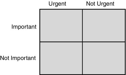
Time Management
There are time bandits out there who will steal your valuable time for their own purposes or just to occupy themselves around the water cooler. How do you determine what is the highest priority and what activities should be ranked low on the list of priorities? Write down the chart shown in Fig. 10.1 on a piece of paper or whiteboard. Now classify all of the activities for the job into one of the four fields. You will note that those that are urgent and important and those that are not urgent and not important require little decision making about what to do. The challenge lies in those tasks that are urgent but not important and those that are not urgent but are important. Focus on the not urgent but important tasks, and the project will go much smoother.1
Good project management involves the following elements, which should be spelled out in the specifications:
• Determine the goals, deliverables, and scope of the project.
• Identify the boundaries and relationships to other project participants.
• Plan the project. Create a work breakdown structure and understand project controls.
• Provide the personnel and material resources to complete the project by the completion date in conformance with the specifications. Schedule materials and manpower in order to meet the published project schedule.
• Safeguard delivered equipment until it is installed.
• Coordinate the work of this project with the work of other trades.
• Schedule each major milestone in the work of the project.
• Ensure project schedule compliance and take corrective action when the schedule is not maintained.
• Close out the project in accordance with the specifications.
Training
The objectives of training are to familiarize the operators and maintenance technicians with the attributes, programming, and software-operating environment. The owner’s administrator, supervisors, and operators need training on those three levels of system operation. The owner’s or contractor’s installers and maintenance personnel need training on how to install, commission, and maintain the system. The specifications should require evidence of training for all these.
The level of training depends on the project. For small projects, a few hours of owner’s personnel training may be adequate. For enterprise systems, my specifications require separate training for each level of the owner’s personnel. The training sessions are recorded with audio and screen image recording software. The recorded screen and audio are edited down to essential discussion and screen shots, and a DVD is produced for each level for later training sessions.
For all projects, the contractor should be required to certify manufacturer’s training for the personnel who are installing, commissioning, and maintaining the system.
Testing
Include language stating that system testing is a basic service. Testing will be discussed in detail later in the specification, under Section 3: Execution.
Warranty
In the security industry, warranties are a contentious issue. I specify minimum acceptable warranty language that must be included by the integrator in their warranty. The language in the specifications about the warranty indicates that any other language in the warranty that is in conflict with the language in the specifications is contractually void.
The warranty section should require a warranty of a given time period (typically 1 year).
The purpose of the warranty should be stated:
• Guarantee the repair of any malfunction or system installation deficiency during the warranty period.
• Commit to covering the cost of correcting any installation deficiency.
• State when the warranty will begin and end.
• Discuss the issue of transferability of the warranty to other parties (not allowed by me in my specification).
• Indicate how the warranty must be transmitted. For example, if a substitute warranty is signed for by the owner, the original warranty is void under the specifications, and the signature is unenforceable.
• Indicate that the contractor must register all equipment of this work with the manufacturers in the name of the owner.
• Discuss any rules for subcontracting warranty repair work.
• Discuss how emergency and non-emergency repairs are to be handled.
• List hours of service.
• Discuss how chronic problems with the system are to be handled.
Precedence
This article is not typically used in new construction projects because its elements are normally included in Division 0, General Provisions. This article instructs the installer as to the order or precedence of documents and what to do if any conflict occurs during the project. Change orders, language for training, submittals, and screens are all included in this article.
System Descriptions
I describe the total integrated system and each subsystem that makes it up by using four distinct methods to describe each element of the overall system.
Purpose
• What is the purpose of the system or subsystem?
• What does the owner expect to receive as a benefit for his or her investment?
Environment
What is the environment in which the system operates?
• What is the physical environment? Is the system indoors or outdoors? Is it operating in a harsh environment, such as an offshore oil platform, or in desert conditions that can reach 140 degrees, or in the Arctic, where temperatures might be well below zero?
• What is the security environment? What threats is the system helping to defend against? What assets are under protection?
• What is the operational environment? Is the system operated by trained employed staff or by contract guards who might have a high turnover?
Functions
What functions do we want each part of each subsystem to perform? List every desired function here. If it is not listed, it is not a specification requirement, and the system becomes acceptable without that function. This is where poor specifiers often get bitten for “extra services” by the contractor. If you do not ask for it, you cannot expect to get it.
Attributes
What physical attributes must the system have in order to perform the functions that are specified? Do not mistake this for a product or installation specification. This describes the general configuration of the hardware architecture of the system elements, not the specific products to be used. You might be unpleasantly surprised to discover that the contractor’s idea of how the system should be configured is dramatically different from your design concept. State the design concept clearly so that there will be no misunderstanding.
Systems may Include the Following
Integrated Security System Overview
Provide an overview of what the entire system is, what subsystems it has, and what the overall system should do.
Monitoring and Control System
Usually one of the systems will provide the Graphical User Interface to operate the other systems. List all of the components of the system, including field components, infrastructure components, and server/workstation and software components.
Alarm/Access Control System
Describe the alarm/access control system in its entirety. List all of the components of the system, including field components, infrastructure components, and server/workstation and software components.
Under functions, describe how alarms should work, identification, grouping, scheduling, and operation. Describe alarm types and how alarmed state actions should be handled when they occur.
Describe output control functions, including basic output controls, global I/O functions, data inputs and outputs, and interfaces to central station alarm receivers and panels.
Describe access control functions, including basic principles, credentials, time zones, daylight savings time, schedules and holidays, access levels and access groups, and temporary and permanent access levels. Discuss user types, user functions, and advanced access control system functions such as first card unlock, two-man rule, global anti-passback, global occupancy rule, mustering, guard tours, and card formats. Describe operator functions, including functions for administrators, supervisors, and operators. Explain ID credentialing functions and photo ID functions. List visitor management functions and monitoring and control functions, including alarm monitoring and access control monitoring. Make reference to other appropriate sections, such as the monitoring and control sub-system. Describe operator controls, including remote access granting, and any other applicable controls. List database and reporting functions. Finally, list archiving functions.
Digital or Analog Video System
List all of the components of the video system, including field components, infrastructure and server/workstation components, and software components.
Under functions, list each function of each component that is required. Remember, if it is not specified, it is not required.
• What does the system do? How does it do it?
• What display functions will the system perform, including alarm response, video guard tours, video pursuit, and surveillance?
• How will the console operate?
• How will the system relate to other subsystems and other building systems, such as lights and parking?
Security Intercom System
Describe the field, infrastructure, and server/workstation components of the system.
Describe how the system works in detail for users, lobby desks, and console operators.
Describe how the system interfaces and interoperates with other related systems, including call logging and event spawning (e.g., video call-ups)
Describe the type of intercom systems and their applications, including access assistance IC stations, emergency phones, elevator intercoms, suspicious subject interview intercoms, and intercom bullhorns.
Interfaces Between Subsystems
List every interface between every system that is part of this integrated security system, installed by the security system contractor.
• What systems are interfaced together and to perform what functions?
• How do the interfaces work and how are they connected?
Interfaces to Systems by Other Contractors
List every interface to every system by other contractors.
• What systems are interfaced together and to perform what functions?
• How do the interfaces work and how are they connected?
System Infrastructure
Describe the overall system infrastructure, including TCP/IP building, intrabuilding, and enterprise architectures.
• Video coax elements
• Intercom audio wiring elements
• Spare parts
Describe what type of spares are required, how many of what, and how they are to be handed over to the client.
Submittals
Bid Submittal
State the obligation to provide all listed submittals, including
• Alternate bids
• Renewable annual maintenance agreement
Shop and Field Submittal
Describe the submittal components:
Shop and field drawings: Identify all of the required elements, typically including a title sheet, schedules of circuits and equipment, floor plans, reflected ceiling plans, physical mounting details, single-line diagrams, schematic diagrams, and wiring diagrams.
Manufacturers’ data sheets: Data sheets of each major product.
Bill of quantities: A list of all products by location or system.
Record drawing submittal: The record drawings or “as-builts,” as they are known in the industry, are a record of how the system was actually built, not just how it was designed. In other respects, they echo the shop and field drawings.
Definitions: List all of the words that have special meaning in the specifications.
Specifications Section 2
Introduction: Section 2 lists acceptable products. Describe how the contractor can submit alternates. List each specified product for each of the subsystems in detail. There are three acceptable ways to do this:
• List each product by its description in detail, never mentioning any brand or model.
• List a number of acceptable brands and models.
• List a single brand and model that bidders can use as a benchmark against which other acceptable alternates can be submitted. If this method is used, those products should be widely available by a range of possible bidders.
List acceptable components for general components, including terminal strips, racks, and relays.
System Infrastructure
In this section, list all of the switches, router, firewall, fiber-optic media converters, RS-485/RS-232 media converters, and others.
Monitoring and Control System
In this section, list the servers and workstations, external storage media, operating systems, microphones and speakers, footswitches, and any other console devices, such as monitor mounts, desks, and ergonomic chairs. Do not list application programs except as they relate to the management of the computers. Application programs should be listed under the systems they serve.
Digital Video System
The digital video system section should list any cameras, lenses, mounts, enclosures, codecs, application software, and other DVS items.
Voice Communications System
List any field intercom stations and interface devices, intercom master stations, switches, and software.
Alarm/Access Control System
List all access control devices, including
• Photo ID equipment (e.g., digital camera, lamp, background, badge holders, badge printers, clips, lanyards)
• Electrified door locks
• Door position switches
• Request-to-exit devices
• Infrared
• Electrified panic hardware
• Push buttons, etc.
• Motion alarms
• Other alarms
• Output control devices
• Access control software
• Perimeter detection system: software, hardware, cable, attaching devices, interface devices
• Miscellaneous products
• Spare parts
Specifications Section 3
Section 3 describes how the system is to be constructed, tested, and accepted, including the following:
• Work to be performed immediately upon award of contract
Project familiarization and mobilization
Preliminary interdiscipline coordination
Permits and inspections
Shop and field drawings submittal
• Work to be performed at the contractor’s shop console and rack fabrication
Other preparatory information
• Work to be performed at the project site
Pulling wire
Power coordination
Product delivery, storage, and handling
Safeguards and protections
Safety barriers
Protection
Device installation, terminations, and adjustments
Final interdiscipline coordination
Grounding and powering procedures
I recommend the use of hospital-grade grounding and powering practices. This involves the use of a single ground bar at the main electrical panel to the building, with all grounds of this system going back to that ground bar without splices.
The designer should create text to describe exactly what kind of grounding practices are acceptable. Shielding should be described. Requirements to document power and ground, panels, and breakers should be explained.
Wire and Cable Installation Practices
This section should include
• Conduit and wire pulling practices
• Wire lacing and dressing standards
• Prohibitions against class mixing
• Wire tagging
• Other standards and practices as appropriate
Commissioning: System Setup and Configurations
• Final hardware configurations and testing.
• Camera focusing, etc.
• Perimeter alarm balancing, etc.
• Wireless node configurations, balancing, and any other appropriate configurations.
• Setting up operating systems and domains
• User authorizations
• System configurations
• Application program loading and configurations
• Enterprise system configurations
System Testing: Testing Overview
• Preliminary checks and testing requirements
Acceptance Testing
After the system is tested by the contractor to his or her satisfaction, acceptance testing begins.
• Statement of the scope of the required tests
• Test scheduling readiness and documentations
• Wireless testing
• Infrastructure testing
• System testing
• Remedial correction of testing observations
Project Completion
Microlevel Design: The Threads That Knit Together the Pieces of the Big Picture
Schedules
For contract drawings (issued for bid), schedules (spreadsheets) should be illustrated in the drawing set to assist the bidding contractors in understanding the system sufficiently to bid. For shop and field drawings (drawings by the installing contractor), schedules should be provided in the drawing set to assist the installers in understanding the system sufficiently to install it correctly and with the minimum amount of field decision time. The shop and field schedules should also provide all the information necessary for the purchasing department to acquire all needed materials.
Construction Drawings: Device Schedules by System
System Infrastructure
The system infrastructure schedule outlines in spreadsheet form all of the system infrastructure elements, including switches, routers, fiber optic communications nodes, uninterruptible power supplies, and the like. Any device that connects system elements together or supports their stable and safe operation should be listed. At a minimum, spreadsheet fields should include the site, building, location, floor, area, device by category number of ports, and remarks.
Control and Monitoring System
The control and monitoring system is designated as a separate system on larger security systems and may be included as part of a subsystem or smaller system. This system may include servers and workstations, video monitors, radios, headphones, keypads, mice, and the like, plus a remarks field. At a minimum, spreadsheet fields should include the site, building, location, floor, area, device by category, device specifications (if relevant for bid), and the like.
Alarm/Access Control System
The alarm/access control system schedule should include credential readers, locks, request-to-exit devices, door position switches, alarm points, output controls, alarm/access control system panels, parking gate controllers, and remarks. At a minimum, the spreadsheet should include site, building, floor, area, devices by category, and remarks.
Digital or Analog Video System
The video system schedules should include cameras, lenses, pan/tilt drives, enclosures, codecs (multiplexers, quad units, and matrix switches, if analog), video keyboards, and the like. At a minimum, the spreadsheet should include site, building, floor, area, devices by category, and remarks.
Security Intercom System
The security intercom system schedule may be on its own table or might be included as part of the video system, if so equipped. The schedule should include field intercom stations, security intercom stations, intercom bullhorns, amplifiers, microphones, headphones, intercom master stations, and matrix switches (if analog). At a minimum, the spreadsheet should be formatted as discussed previously.
System Interfaces
System interfaces may be on their own schedule or could be implemented into the others. System interfaces should include the connection points between systems and the functions to be performed.
Power
Power schedules should include the high-voltage power drops locations and the devices served at each location. Some designers prefer to include low-voltage power supplies in this schedule. The spreadsheet should be formatted as discussed previously.
Cable
A system cable spreadsheet should include the cable types, brand, model of cable, and the outside diameter and rating of the cable (e.g., voltage class of insulation, indoor, plenum [above ceiling] rated, direct burial rated)
Conduit and Fill
Some designers place conduit and fill schedules on each floor, site, or ceiling plan in the construction drawing package. This made good sense in the old days when virtually every system utilized very similar system wiring architecture. However, as system architectures become more diverse, it can in fact be confusing to the bidders to dictate a specific wiring scheme when the products they prefer to submit use another. For many systems, I now leave conduit and fill schedules to the shop and field drawing set, to be submitted by the contractor who is awarded the project. Conduit and fill schedules, if shown on the construction drawing set, should include the conduit number for each conduit shown on that specific plan, its size, and the types and numbers of wires to be in each conduit (the fill).
General Network Device Configuration Schedules
Network device configurations should be illustrated conceptually on a configuration schedule. The configuration schedule should have two parts or be shown as three schedules (hardware configuration, firmware/software configuration, and user access configurations). The schedule should include all the basic requirements the security system designer intends for the system to operate under as a prerequisite to its stable and safe operation. These may include disabling unused switcher ports, access classes and permissions, for example.
Shop and Field Drawings
In addition to the schedules identified previously for construction drawing packages, shop and field drawings should also include conduit and fill schedules as described previously, if not included in the construction drawing package.
Device Wiring Schedules
A device wiring schedule (also called “run sheet”) will list the exact input and output connections from and to every device in the security system. These are typically done by cabinet, rack, or console assembly. Each schedule will show all of the devices for that assembly, its connection point, and the connection by connector type and wiring type. This will be correlated to its source or destination assembly, device, and wiring point. A good practice is to show this assembly in the center of the spreadsheet and the source points to the left and destination points to the right of the schedule.
Configuration Schedules
System configuration schedules should include the exact desired configuration for each programmable device. Configurations may be shown for hardware devices, firmware or software devices, and users by class.
Physical Details
Physical details are drawings that identify all of the mounting and installation requirements for each device. These may include mounting height, positioning, structural mounting requirements, conduit and box connections, and the like.
System Interfacing Details
System interfacing details illustrate connections between systems that are necessary to create integration functions. These should usually also include a brief sequence of operation of theory of operation, not in conflict with the description provided in the specifications. Interfacing details should be provided from and to other systems being interfaced, possibly including elevators, parking, building automation, PABX, VoIP, radio, lighting, signage, concrete, and landscape.
Revised Construction Budget
Following completion of the construction drawing package, it is common to make a final revision to the construction budget.
Complete Specification
The complete specification provided as part of the construction drawing package must include all of the system requirements, fleshing out the outline provided in the design development issue.
Review Drawings, Specifications, and Prioritized Budgets
Following submission of the final construction documents package, the client may perform a final review. This may also include an interdiscipline coordination review. The client will return the package with final comments.
Revise after Review
Following receipt of the final comments, the designer will perform final corrections and issue the package for bid through proper project management channels.
Summary
Preliminary (schematic phase) design work includes the basis for design, research drawing and specification resources, and preliminary budgeting. The basis for design explains what the system should be from an interpretation of implementation of security policies. Drawing resources include security system device placements and types, access control zones, a study of codes and regulations, safety issues, and power source locations. A list of interdiscipline coordination issues should be developed. System technology goals should be decided.
The big picture of design includes three views:
• How the system devices relate to the building and site
• How the system devices relate to the conduit system
• How the system devices relate to other system devices
Plans, risers, and physical details provide the first two views. Single-line diagrams provide the third.
Specifications provide the description and legal requirements for carrying out the construction work. Specifications are in three sections:
• Section 1 includes system descriptions and contractual requirements.
• Section 2 describes acceptable products.
• Section 3 describes acceptable installation practices.
Questions and Answers
1. Which information does not belong in the security drawings?
a. How the system devices relate to the building and site
b. How the system devices relate to the conduit system
c. How the system devices relate to other system devices
d. How the system devices relate to the buyer
2. Which drawings do not show how security devices relate to the conduit system?
b. Specifications
c. Schematics
d. Schedules
3. Power drop points can be shown on:
b. Risers
c. Physical details
d. All of the above.
4. Single-line diagrams are also commonly called:
b. Detailed schematics
c. Block diagrams
d. None of the above
5. CSI specifications are laid out in ___ sections.
b. 3
c. 4
d. 5
6. Bid drawings must be designed so that any qualified contractor can bid:
b. Efficiently
c. A variety of different manufacturers’ products
d. None of the above
7. Project management is all about:
a. Delivering high-quality projects
b. Delivering high-quality projects on time
c. Delivering projects on time
d. None of the above
8. Specifications should state the _________ of the system:
b. Functions
c. Attributes
d. All of the above
9. Section 2 lists acceptable:
b. Execution and installation methods
c. Definition of the system
d. All of the above
10. Common system schedules include:
b. Alarm/Access control and/or video system
c. Cables
d. All of the above
Answers: 1: d, 2: d, 3: d, 4: c, 5: b, 6: c, 7: b, 8: d, 9: a, 10: d