Chapter 3. Network Protocols and Communications
Objectives
Upon completion of this chapter, you will be able to answer the following questions:
![]() Why are protocols necessary in communication?
Why are protocols necessary in communication?
![]() What is the purpose of adhering to a protocol suite?
What is the purpose of adhering to a protocol suite?
![]() What is the role of standards organizations in establishing protocols for network interoperability?
What is the role of standards organizations in establishing protocols for network interoperability?
![]() How are the TCP/IP model and the OSI model used to facilitate standardization in the communication process?
How are the TCP/IP model and the OSI model used to facilitate standardization in the communication process?
![]() Why have RFCs become the process for establishing standards?
Why have RFCs become the process for establishing standards?
![]() What is the RFC process?
What is the RFC process?
![]() How does data encapsulation allow data to be transported across the network?
How does data encapsulation allow data to be transported across the network?
![]() How do local hosts access local resources on a network?
How do local hosts access local resources on a network?
![]() How do local hosts access remote resources on a network?
How do local hosts access remote resources on a network?
Key Terms
This chapter uses the following key terms. You can find the definitions in the Glossary.
Network Access Protocols page 106
Transmission Control Protocol/IP (TCP/IP) page 106
standards organizations page 110
Internet Society (ISOC) page 110
Internet Architecture Board (IAB) page 110
Internet Engineering Task Force (IETF) page 110
Internet Research Task Force (IRTF) page 110
Institute of Electrical and Electronics Engineers (IEEE) page 111
International Organization for Standardization (ISO) page 112
Open Systems Interconnection (OSI) reference model page 112
Internet Corporation for Assigned Names and Numbers (ICANN) page 113
Internet Assigned Numbers Authority (IANA) page 113
TCP/IP protocol model page 116
Request for Comments (RFC) page 118
protocol data unit (PDU) page 125
destination IP address page 127
Address Resolution Protocol (ARP) page 130
Introduction (3.0.1.1)
More and more, it is networks that connect us. People communicate online from everywhere. Conversations in boardrooms spill into instant message chat sessions, and online debates continue at school. New services are being developed daily to take advantage of the network.
Rather than developing unique and separate systems for the delivery of each new service, the network industry as a whole has adopted a developmental framework that allows designers to understand current network platforms, and maintain them. At the same time, this framework is used to facilitate the development of new technologies to support future communications needs and technology enhancements.
Central to this developmental framework is the use of generally accepted models that describe network rules and functions.
Within this chapter you will learn about these models, as well as the standards that make networks work, and how communication occurs over a network.
Class Activity 3.0.1.2: Designing a Communications System
In this activity you will design a communications model in a customer service scenario.
Network Protocols and Standards (3.1)
In this section you will learn about some of the protocols that work together in computer networks.
Protocols (3.1.1)
Protocols for computer communications over networks were agreed upon by groups of computer professionals. The best way to understand how these protocols work is to compare them to communications protocols you use every day.
Protocols: Rules that Govern Communications (3.1.1.1)
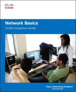
All communication, whether it is face-to-face or over a network, is governed by rules called protocols. These protocols vary depending on the type of conversation. In our day-to-day personal communication, the rules we use to communicate over one medium, such as a telephone call, are not necessarily the same as the rules for using another medium, such as sending a letter.
Think of how many different rules or protocols govern all the different methods of communication that exist in the world today. For example, consider two people communicating face-to-face. First, they must agree on how they will communicate. If they agree to communicate using voice, they must agree on the language. Then, they must actually have a message to share, and format that message in a way that is understandable. Each of these tasks describes a protocol put in place to accomplish communication. Similarly, successful communication between hosts on a network requires the interaction of many different protocols. A group of interrelated protocols necessary to perform a communication function is called a protocol suite. Protocol suites are implemented by hosts and networking devices in software, hardware, or both.
One of the best ways to visualize how the protocols within a suite interact is to view the interaction as a stack. A protocol stack shows how the individual protocols within a suite are implemented. The protocols are viewed in terms of layers, with each higher-layer service depending on the functionality defined by the protocols shown in the lower layers. The lower layers of the stack are concerned with moving data over the network and providing services to the upper layers, which are focused on the content of the message being sent. As Figure 3-1 shows, we can use layers to describe the activity occurring in our face-to-face communication example. At the bottom layer, the physical layer, there are two people, each with a voice that can say words out loud. At the second layer, the rules layer, there is an agreement to speak in a common language. At the top layer, the content layer, there are words that are actually spoken. This is the content of the communication.
Were we to witness this conversation, we would not actually see layers floating in space, of course. The use of layers is a model that provides a way to conveniently break a complex task into parts and describe how they work.
Network Protocols (3.1.1.2)
At the human level, some communication rules are formal and others are simply understood based on custom and practice. For devices to successfully communicate, a network protocol suite must describe precise requirements and interactions. Networking protocols define a common format and set of rules for exchanging messages between devices. Some common networking protocols are Internet Protocol (IP), Hypertext Transfer Protocol (HTTP), and Dynamic Host Configuration Protocol (DHCP).
Networking protocols describe the following processes:
![]() How the message is formatted or structured
How the message is formatted or structured
![]() The process by which networking devices share information about pathways with other networks
The process by which networking devices share information about pathways with other networks
![]() How and when error and system messages are passed between devices
How and when error and system messages are passed between devices
![]() The setup and termination of data transfer sessions
The setup and termination of data transfer sessions
For example, IP defines how a packet of data is delivered within a network or to a remote network. The information in the IPv4 protocol is transmitted in a specific format so that the receiver can interpret it correctly. This protocol is not much different from the protocol used to address an envelope when mailing a letter. The information must adhere to a certain format or else the letter cannot be delivered to the destination by the post office.
Interaction of Protocols (3.1.1.3)
An example of using the protocol suite in network communications is the interaction between a web server and a web client. This interaction uses a number of protocols and standards in the process of exchanging information between the web server and web client. The different protocols work together to ensure that the messages are received and understood by both parties. These protocols can usually be defined by the layer function they perform. Some examples of these protocols are
![]() Application layer protocol: Hypertext Transfer Protocol (HTTP) is a protocol that governs the way a web server and a web client interact. HTTP defines the content and formatting of the requests and responses that are exchanged between the client and server. Both the client and the web server software implement HTTP as part of the application. HTTP relies on other protocols to govern how the messages are transported between the client and server.
Application layer protocol: Hypertext Transfer Protocol (HTTP) is a protocol that governs the way a web server and a web client interact. HTTP defines the content and formatting of the requests and responses that are exchanged between the client and server. Both the client and the web server software implement HTTP as part of the application. HTTP relies on other protocols to govern how the messages are transported between the client and server.
![]() Transport layer protocol: Transmission Control Protocol (TCP) is the transport protocol that manages the individual conversations between web servers and web clients. TCP divides the HTTP messages into smaller pieces, called segments. These segments are sent between the web server and client processes running at the destination host. TCP is also responsible for controlling the size and rate at which messages are exchanged between the server and the client.
Transport layer protocol: Transmission Control Protocol (TCP) is the transport protocol that manages the individual conversations between web servers and web clients. TCP divides the HTTP messages into smaller pieces, called segments. These segments are sent between the web server and client processes running at the destination host. TCP is also responsible for controlling the size and rate at which messages are exchanged between the server and the client.
![]() Internet Protocol (IP): IP is responsible for taking the formatted segments from TCP, encapsulating them into packets, assigning them the appropriate addresses, and delivering them across the best path to the destination host.
Internet Protocol (IP): IP is responsible for taking the formatted segments from TCP, encapsulating them into packets, assigning them the appropriate addresses, and delivering them across the best path to the destination host.
![]() Network access protocols: Network access protocols describe two primary functions: communication over a data link, and the physical transmission of data on the network media. Data-link management protocols take the packets from IP and format them to be transmitted over the media. The standards and protocols for the physical media govern how the signals are sent and how they are interpreted by the receiving clients. An example of a network access protocol is Ethernet.
Network access protocols: Network access protocols describe two primary functions: communication over a data link, and the physical transmission of data on the network media. Data-link management protocols take the packets from IP and format them to be transmitted over the media. The standards and protocols for the physical media govern how the signals are sent and how they are interpreted by the receiving clients. An example of a network access protocol is Ethernet.
Protocol Suites (3.1.2)
In the previous section you learned that protocols are designed to perform very specific tasks efficiently, and that groups of protocols that work together to successfully complete the communication process are referred to as protocol suites. This section explores how protocol suites were developed and how they operate.
Protocol Suites and Industry Standards (3.1.2.1)
As stated previously, a protocol suite is a set of protocols that work together to provide comprehensive network communication services. A protocol suite may be specified by a standards organization or developed by a vendor.
The protocols IP, HTTP, and DHCP are all part of the Internet protocol suite known as Transmission Control Protocol/Internet Protocol (TCP/IP). The TCP/IP protocol suite is an open standard, meaning these protocols are freely available to the public, and any vendor is able to implement these protocols on their hardware or in their software.
A standards-based protocol is a process or protocol that has been endorsed by the networking industry and ratified, or approved, by a standards organization. The use of standards in developing and implementing protocols ensures that products from different manufacturers can interoperate successfully. If a protocol is not rigidly observed by a particular manufacturer, their equipment or software may not be able to successfully communicate with products made by other manufacturers.
In data communications, for example, if one end of a conversation is using a protocol to govern one-way communication and the other end is assuming a protocol describing two-way communication, in all probability, no data will be exchanged.
Some protocols are proprietary. Proprietary, in this context, means that one company or vendor controls the definition of the protocol and how it functions. Some proprietary protocols can be used by different organizations with permission from the owner. Others can only be implemented on equipment manufactured by the proprietary vendor. Examples of proprietary protocols are AppleTalk and Novell NetWare.
Several companies may even work together to create a proprietary protocol. It is not uncommon for a vendor (or group of vendors) to develop a proprietary protocol to meet the needs of its customers and later assist in making that proprietary protocol an open standard. For example, Ethernet was a protocol originally developed by Bob Metcalfe at the Xerox Palo Alto Research Center (PARC) in the 1970s. In 1979, Metcalfe formed his own company, 3COM, and worked with Digital Equipment Corporation (DEC), Intel, and Xerox to promote the “DIX” (Digital, Intel, Xerox) standard for Ethernet. In 1985, the Institute of Electrical and Electronics Engineers (IEEE) published the IEEE 802.3 standard that was almost identical to Ethernet. Today, 802.3 is the common standard used on local-area networks (LANs). As another, more recent example, Cisco opened its Enhanced Interior Gateway Routing Protocol (EIGRP) as an informational Request for Comments (RFC) to meet the needs of customers who desire to use the protocol in a multivendor network.
Creation of the Internet and Development of TCP/IP (3.1.2.2)
The IP suite is a suite of protocols required for transmitting and receiving information using the Internet. It is commonly known as TCP/IP because the first two networking protocols defined for this standard were TCP and IP. The open standards–based TCP/IP has replaced other vendor proprietary protocol suites, such as Apple’s AppleTalk and Novell’s Internetwork Packet Exchange/Sequenced Packet Exchange (IPX/SPX).
The first packet-switched network and the predecessor to today’s Internet was the Advanced Research Projects Agency Network (ARPANET), which came to life in 1969 by connecting mainframe computers at four locations. ARPANET was funded by the U.S. Department of Defense for use by universities and research laboratories. Bolt, Beranek and Newman (BBN) was the contractor that did much of the initial development of the ARPANET, including creating the first router, known as an Interface Message Processor (IMP).
In 1973, Robert Kahn and Vinton Cerf began work on TCP to develop the next generation of the ARPANET. TCP was designed to replace ARPANET’s current Network Control Program (NCP). In 1978, TCP was divided into two protocols: TCP and IP. Later, other protocols were added to the TCP/IP suite of protocols, including Telnet, FTP, DNS, and many others.
Activity 3.1.2.2: Internet Timeline
Go to the online course and click the blue points on the timeline to see details about the development of other network protocols and applications.
TCP/IP Protocol Suite and Communication Process (3.1.2.3)
Today, the TCP/IP suite includes dozens of protocols.

Activity 3.1.2.3: Protocol Suites.
Go to the online course page 3.1.2.3 and view the first graphic. Click each protocol to view its description. The protocols are organized in layers using the TCP/IP protocol model.
TCP/IP protocols are included in the internet, transport, and application layers to the application layer when referencing the TCP/IP model. The lower-layer protocols in the data link or network access layer are responsible for delivering the IP packet over the physical medium. These lower-layer protocols are developed by standards organizations, such as IEEE.
The TCP/IP protocol suite is implemented as a TCP/IP stack on both the sending and receiving hosts to provide end-to-end delivery of applications over a network. The 802.3 or Ethernet protocols are used to transmit the IP packet over the physical medium used by the LAN.

Video 3.1.2.3:
Click the second and third graphics to access the animations depicting the steps in the communication process.
The following are the steps in the communication process, using an example of a web server transmitting data to a client:
1. The web server’s Hypertext Markup Language (HTML) page is the data to be sent.
2. The application protocol HTTP header is added to the front of the HTML data. The header contains various information, including the HTTP version the server is using and a status code indicating it has information for the web client.
3. The HTTP application layer protocol delivers the HTML-formatted web page data to the transport layer. The TCP transport layer protocol is used to manage the individual conversation between the web server and web client.
4. The IP information is added to the front of the TCP information. IP assigns the appropriate source and destination IP addresses. This information is known as an IP packet.
5. The Ethernet protocol adds information to both ends of the IP packet, known as a data link frame. This frame is delivered to the nearest router along the path toward the web client. This router removes the Ethernet information, analyzes the IP packet, determines the best path for the packet, inserts the packet into a new frame, and sends it to the next neighboring router toward the destination. Each router removes and adds new data link information before forwarding the packet.
6. This data is transported through the internetwork, which consists of media and intermediary devices.
7. The client receives the data link frames that contain the data, and each protocol header is processed and then removed in the opposite order in which it was added. The Ethernet information is processed and removed, followed by the IP protocol information, then the TCP information, and finally the HTTP information.
8. The web page information is passed on to the client’s web browser software.
Activity 3.1.2.4: Mapping the Protocols of the TCP/IP Suite
Go to the online course to perform this practice activity.
Standards Organizations (3.1.3)
In this section you will learn about the organizations that define protocol standards.
Open Standards (3.1.3.1)
Open standards encourage competition and innovation. They also guarantee that no single company’s product can monopolize the market, or have an unfair advantage over its competition. A good example of this is when purchasing a wireless router for the home. There are many different choices available from a variety of vendors, all of which incorporate standard protocols such as IPv4, DHCP, IEEE 802.3 (Ethernet), and IEEE 802.11 (Wireless LAN). These open standards also allow a client running Apple’s OS X operating system to download a web page from a web server running the Linux operating system. This is because both operating systems implement the open standard protocols, such as those in the TCP/IP suite.
Standards organizations are important in maintaining an open Internet with freely accessible specifications and protocols that can be implemented by any vendor. A standards organization may draft a set of rules entirely on its own or, in other cases, select a proprietary protocol as the basis for the standard. If a proprietary protocol is used, the drafting process usually involves the vendor who created the protocol.
Standards organizations are usually vendor-neutral, nonprofit organizations established to develop and promote the concept of open standards.
Standards organizations include
![]() Internet Society (ISOC)
Internet Society (ISOC)
![]() Internet Architecture Board (IAB)
Internet Architecture Board (IAB)
![]() Internet Engineering Task Force (IETF)
Internet Engineering Task Force (IETF)
![]() Institute of Electrical and Electronics Engineers (IEEE)
Institute of Electrical and Electronics Engineers (IEEE)
![]() International Organization for Standardization (ISO)
International Organization for Standardization (ISO)
Each of these organizations is discussed in more detail in the following sections.
ISOC, IAB, and IETF (3.1.3.2)
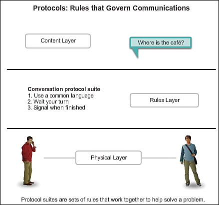
The Internet Society (ISOC) is responsible for promoting open development, evolution, and Internet use throughout the world. ISOC facilitates the open development of standards and protocols for the technical infrastructure of the Internet, including the oversight of the Internet Architecture Board (IAB).
The Internet Architecture Board (IAB) is responsible for the overall management and development of Internet standards. The IAB provides oversight of the architecture for protocols and procedures used by the Internet. The IAB consists of 13 members, including the chair of the Internet Engineering Task Force (IETF). IAB members serve as individuals, not as representatives of any company, agency, or other organization.
The mission of the Internet Engineering Task Force (IETF) is to develop, update, and maintain Internet and TCP/IP technologies. One of the key responsibilities of the IETF is to produce Request for Comments (RFC) documents, which are a memorandum describing protocols, processes, and technologies for the Internet. The IETF consists of working groups (WGs), the primary mechanism for developing IETF specifications and guidelines. WGs are short term, and after the objectives of the group are met, the WG is terminated. The Internet Engineering Steering Group (IESG) is responsible for the technical management of the IETF and the Internet standards process.
The Internet Research Task Force (IRTF) is focused on long-term research related to Internet and TCP/IP protocols, applications, architecture, and technologies. Whereas the IETF focuses on shorter-term issues of creating standards, the IRTF consists of research groups for long-term development efforts. The Internet Research Steering Group (IRSG) oversees some of the current research groups, which include the Anti-Spam Research Group (ASRG), Crypto Forum Research Group (CFRG), Peer-to-Peer Research Group (P2PRG), and Router Research Group (RRG). Figure 3-2 depicts the organization and responsibilities of Internet engineering and research groups.
IEEE (3.1.3.3)
The Institute of Electrical and Electronics Engineers (IEEE, pronounced “I-triple-E”) is a professional organization for those in the electrical engineering and electronics fields who are dedicated to advancing technological innovation and creating standards. As of 2012, IEEE consists of 38 societies, publishes 130 journals, and sponsors more than 1,300 conferences each year worldwide. The IEEE has over 1,300 standards and projects currently under development.
IEEE has more than 400,000 members in more than 160 countries. More than 107,000 of those members are student members. IEEE provides educational and career enhancement opportunities to promote the skills and knowledge within the electronics industry.
IEEE is one of the leading standard-producing organizations in the world. It creates and maintains standards affecting a range of industries, including power and energy, healthcare, telecommunications, and networking. The IEEE 802 family of standards deals with local-area networks and metropolitan-area networks, including both wired and wireless.
The IEEE 802.3 and IEEE 802.11 standards are significant IEEE standards in computer networking. The IEEE 802.3 standard defines Media Access Control (MAC) for wired Ethernet. This technology is usually for LANs, but also has wide-area network (WAN) applications. The 802.11 standard defines a set of standards for implementing wireless local-area networks (WLANs). This standard defines the Open Systems Interconnection (OSI) physical and data link MAC for wireless communications.
ISO (3.1.3.4)
ISO, the International Organization for Standardization, is the world’s largest developer of international standards for a variety of products and services. ISO is not an acronym for the organization’s name; rather, the ISO term is based on the Greek word “isos,” meaning equal. The International Organization for Standardization chose the ISO term to affirm its position as being equal to all countries.
In networking, ISO is best known for its Open Systems Interconnection (OSI) reference model. ISO published the OSI reference model in 1984 to develop a layered framework for networking protocols. The original objective of this project was not only to create a reference model but also to serve as a foundation for a suite of protocols to be used for the Internet. This was known as the OSI protocol suite. However, due to the rising popularity of the TCP/IP suite, developed by Robert Kahn, Vinton Cerf, and others, the OSI protocol suite was not chosen as the protocol suite for the Internet. Instead, the TCP/IP protocol suite was selected. The OSI protocol suite was implemented on telecommunications equipment and can still be found in legacy telecommunications networks.
You may be familiar with some of the products that use ISO standards. The ISO file extension is used on many CD images to signify that they use the ISO 9660 standard for their file system. ISO is also responsible for creating standards for routing protocols.
Other Standards Organizations (3.1.3.5)
Networking standards involve several other standards organizations. Some of the more common ones are
![]() Electronic Industries Alliance (EIA): Previously known as the Electronics Industries Association, the EIA is an international standards and trade organization for electronics organizations. The EIA is best known for its standards related to electrical wiring, connectors, and the 19-inch racks used to mount networking equipment.
Electronic Industries Alliance (EIA): Previously known as the Electronics Industries Association, the EIA is an international standards and trade organization for electronics organizations. The EIA is best known for its standards related to electrical wiring, connectors, and the 19-inch racks used to mount networking equipment.
![]() Telecommunications Industry Association (TIA): The TIA is responsible for developing communications standards in a variety of areas, including radio equipment, cellular towers, Voice over IP (VoIP) devices, satellite communications, and more. Many of its standards are produced in collaboration with the EIA.
Telecommunications Industry Association (TIA): The TIA is responsible for developing communications standards in a variety of areas, including radio equipment, cellular towers, Voice over IP (VoIP) devices, satellite communications, and more. Many of its standards are produced in collaboration with the EIA.
![]() International Telecommunications Union-Telecommunication Standardization Sector (ITU-T): The ITU-T is one of the largest and oldest communications standards organizations. The ITU-T defines standards for video compression, Internet Protocol Television (IPTV), and broadband communications, such as a digital subscriber line (DSL). For example, when dialing another country, ITU country codes are used to make the connection.
International Telecommunications Union-Telecommunication Standardization Sector (ITU-T): The ITU-T is one of the largest and oldest communications standards organizations. The ITU-T defines standards for video compression, Internet Protocol Television (IPTV), and broadband communications, such as a digital subscriber line (DSL). For example, when dialing another country, ITU country codes are used to make the connection.
![]() Internet Corporation for Assigned Names and Numbers (ICANN): ICANN is a nonprofit organization based in the United States that coordinates IP address allocation, the management of domain names used by DNS, and the protocol identifiers or port numbers used by TCP and UDP protocols. ICANN creates policies and has overall responsibility for these assignments.
Internet Corporation for Assigned Names and Numbers (ICANN): ICANN is a nonprofit organization based in the United States that coordinates IP address allocation, the management of domain names used by DNS, and the protocol identifiers or port numbers used by TCP and UDP protocols. ICANN creates policies and has overall responsibility for these assignments.
![]() Internet Assigned Numbers Authority (IANA): IANA is a department of ICANN that is responsible for overseeing and managing IP address allocation, domain name management, and protocol identifiers for ICANN.
Internet Assigned Numbers Authority (IANA): IANA is a department of ICANN that is responsible for overseeing and managing IP address allocation, domain name management, and protocol identifiers for ICANN.
Familiarization with the organizations that develop standards used in networking will help you have a better understanding of how these standards create an open, vendor-neutral Internet, and allow you to learn about new standards as they develop.
Lab 3.1.3.6: Researching Networking Standards
In this lab you will research networking standards organizations and note how those organizations formed the Internet we use today.
Activity 3.1.3.7: Standards Body Scavenger Hunt
Go to the online course to perform this practice activity.
Reference Models (3.1.4)
Reference models are a way to clarify the networking process and enable networking professionals to communicate clearly on issues and developments that arise in the field. It is essential that networking professionals understand reference models and be able to use them in professional interactions.
The Benefits of Using a Layered Model (3.1.4.1)
A layered model, such as the TCP/IP model, is often used to help visualize the interaction between various protocols. A layered model depicts the operation of the protocols occurring within each layer, as well as the interaction of protocols with the layers above and below each layer.
There are benefits to using a layered model to describe network protocols and operations. Using a layered model
![]() Assists in protocol design, because protocols that operate at a specific layer have defined information that they act upon and a defined interface to the layers above and below.
Assists in protocol design, because protocols that operate at a specific layer have defined information that they act upon and a defined interface to the layers above and below.
![]() Fosters competition because products from different vendors can work together.
Fosters competition because products from different vendors can work together.
![]() Prevents technology or capability changes in one layer from affecting other layers above and below.
Prevents technology or capability changes in one layer from affecting other layers above and below.
![]() Provides a common language to describe networking functions and capabilities.
Provides a common language to describe networking functions and capabilities.
There are two basic types of networking models:
![]() Protocol model: This model closely matches the structure of a particular protocol suite. The hierarchical set of related protocols in a suite typically represents all the functionality required to interface the human network with the data network. The TCP/IP model is a protocol model, because it describes the functions that occur at each layer of protocols within the TCP/IP suite.
Protocol model: This model closely matches the structure of a particular protocol suite. The hierarchical set of related protocols in a suite typically represents all the functionality required to interface the human network with the data network. The TCP/IP model is a protocol model, because it describes the functions that occur at each layer of protocols within the TCP/IP suite.
![]() Reference model: This model provides consistency within all types of network protocols and services by describing what has to be done at a particular layer, but not prescribing how it should be accomplished. A reference model is not intended to be an implementation specification or to provide a sufficient level of detail to define precisely the services of the network architecture. The primary purpose of a reference model is to aid in clearer understanding of the functions and processes involved.
Reference model: This model provides consistency within all types of network protocols and services by describing what has to be done at a particular layer, but not prescribing how it should be accomplished. A reference model is not intended to be an implementation specification or to provide a sufficient level of detail to define precisely the services of the network architecture. The primary purpose of a reference model is to aid in clearer understanding of the functions and processes involved.
The OSI model is the most widely known internetwork reference model. It is used for data network design, operation specifications, and troubleshooting.
As shown in Figure 3-3, the TCP/IP and OSI models are the primary models used when discussing network functionality. Designers of network protocols, services, or devices can create their own models to represent their products. Ultimately, designers are required to communicate to the industry by relating their product or service to either the OSI model or the TCP/IP model, or to both.

The OSI Reference Model (3.1.4.2)
Initially the OSI model was designed by the ISO to provide a framework on which to build a suite of open systems protocols. The vision was that this set of protocols would be used to develop an international network that would not be dependent on proprietary systems.
Ultimately, the speed at which the TCP/IP-based Internet was adopted, and the rate at which it expanded, caused the development and acceptance of the OSI protocol suite to lag behind. Although a few of the developed protocols using the OSI specifications are widely used today, the seven-layer OSI model has made major contributions to the development of other protocols and products for all types of new networks.
The OSI model provides an extensive list of functions and services that can occur at each layer. It also describes the interaction of each layer with the layers directly above and below it. Although the content of this course is structured around the OSI reference model, the focus of discussion is the protocols identified in the TCP/IP protocol model.
Activity 3.1.4.2: The OSI Reference Model
Go to the online course to perform this practice activity.
Whereas the TCP/IP model layers are referred to only by name, the seven OSI model layers are more often referred to by number rather than by name. For instance, the physical layer is referred to as Layer 1 of the OSI model.
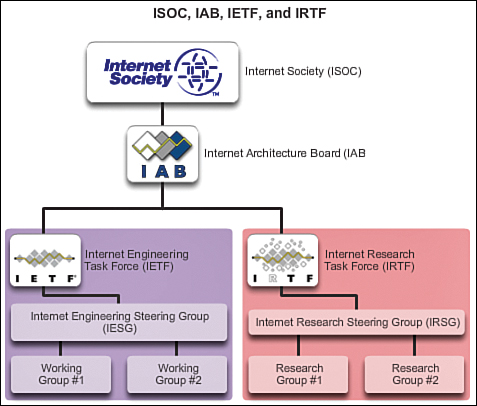
The TCP/IP Protocol Model (3.1.4.3)
The TCP/IP protocol model for internetwork communications was created in the early 1970s and is sometimes referred to as the Internet model. As shown in Figure 3-4, it defines four categories of functions that must occur for communications to be successful. The architecture of the TCP/IP protocol suite follows the structure of this model. Because of this, the Internet model is commonly referred to as the TCP/IP model.
Most protocol models describe a vendor-specific protocol stack. However, because the TCP/IP model is an open standard, one company does not control the definition of the model. The definitions of the standard and the TCP/IP protocols are discussed in a public forum and defined in a publicly available set of RFCs. The RFCs contain both the formal specification of data communications protocols and resources that describe the use of the protocols.
The RFCs also contain technical and organizational documents about the Internet, including the technical specifications and policy documents produced by the IETF.
Comparing the OSI Model with the TCP/IP Model (3.1.4.4)
The protocols that make up the TCP/IP protocol suite can be described in terms of the OSI reference model. In the OSI model, the network access layer and the application layer of the TCP/IP model are further divided to describe discrete functions that must occur at these layers.
At the network access layer, the TCP/IP protocol suite does not specify which protocols to use when transmitting over a physical medium; it only describes the handoff from the Internet layer to the physical network protocols. OSI Layers 1 and 2 discuss the necessary procedures to access the media and the physical means to send data over a network.
As shown in Figure 3-5, the critical parallels between the two network models occur at OSI Layers 3 and 4. OSI Layer 3, the network layer, is almost universally used to describe the range of processes that occur in all data networks to address and route messages through an internetwork. IP is the TCP/IP suite protocol that includes the functionality described at OSI Layer 3.
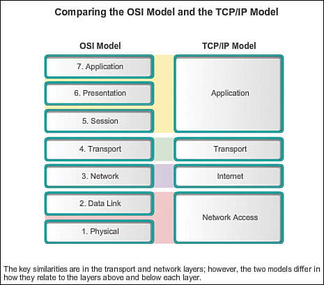
Layer 4, the transport layer of the OSI model, describes general services and functions that provide ordered and reliable delivery of data between source and destination hosts. These functions include acknowledgement, error recovery, and sequencing. At this layer, the TCP/IP protocols TCP and User Datagram Protocol (UDP) provide the necessary functionality.
The TCP/IP application layer includes a number of protocols that provide specific functionality to a variety of end-user applications. The OSI model Layers 5, 6, and 7 are used as references for application software developers and vendors to produce products that operate on networks.
Activity 3.1.4.5: Identify Layers and Functions
Go to the online course to perform this practice activity.
Packet Tracer Activity 3.1.4.6: Investigating the TCP/IP and OSI Models in Action
This simulation activity is intended to provide a foundation for understanding the TCP/IP protocol suite and the relationship to the OSI model. Go to the online course for more information and to perform this practice activity.
Using Requests for Comments (3.2)
In this section you will learn about RFC documents and their processes.
Why RFCs (3.2.1)
Designing standards to be used in network communications is and always has been very much a collaborative effort. Early developers of these standards recognized that in order to keep track of the many ideas and comments being shared, a system for tracking and publishing them needed to be put in place. The RFC process is the answer to that need.
Request for Comments (RFC) (3.2.1.1)
Request for Comments (RFC) is an official document that specifies standards and protocols related to the Internet and TCP/IP. RFCs are usually published by the IETF, but can also come from the IAB, IRTF, or independent submitters.
Note
Not all RFCs define standards, but the standards are referenced most often in networking. Each protocol in the TCP/IP suite is documented and updated using the RFC process.
Some protocols have multiple RFCs to describe different aspects of the protocol. The following is a list of some of the current RFCs for common TCP/IP protocols:
![]() HTTP: RFC 2616, Hypertext Transfer Protocol - HTTP/1.1
HTTP: RFC 2616, Hypertext Transfer Protocol - HTTP/1.1
![]() DHCP: RFC 2131, Dynamic Host Configuration Protocol
DHCP: RFC 2131, Dynamic Host Configuration Protocol
![]() IPv4: RFC 791, Internet Protocol
IPv4: RFC 791, Internet Protocol
![]() IPv6: RFC 2460, Internet Protocol, Version 6 (IPv6) Specification
IPv6: RFC 2460, Internet Protocol, Version 6 (IPv6) Specification
Some RFCs were created with a sense of humor and were never intended to be used as a standard. RFC 1149 describes an experimental method for delivering IPv4 packets using carrier pigeons. This standard was extended in RFC 6214 to include delivery of IPv6 packets using the same carrier pigeons. Of course this is all meant in fun, but nonetheless these are official IETF informational RFCs. The humorous RFCs are usually published on April 1 (April Fools’ Day in the United States) and are meant as pranks.
Individual RFCs are publicly and freely accessible at http://www.rfc-editor.org/index.html.
History of RFCs (3.2.1.2)
On October 29, 1969, the ARPANET came to life with the first message being sent from a mainframe computer at UCLA to a mainframe computer at Stanford Research Institute.
BBN won the contract to build and operate the Interface Message Processors (IMPs), the forerunners to today’s modern routers. IMPs were computers with specialized interfaces and software the size of a refrigerator and cost about $100,000 in 1969 U.S. dollars.
Steve Crocker at UCLA had been working on the IMP software and wanted to solicit opinions from others working on the project. In a memorandum entitled “Host Software,” he asked others in the development of the ARPANET for their opinions and ideas concerning the IMP software. Needing to track documents of this type, he chose the modest phrase “Request for Comments,” along with the number “1” indicating the first number in the sequence. This type of memorandum, more commonly known by its acronym RFC, became the method the early developers of the ARPANET chose to discuss and document standards. At the time there were a very limited number of people working on the development of the ARPANET, so the process was much more informal than it is today.
Today, the Internet is a much different place and a formal structure is used to propose, develop, and implement Internet and TCP/IP standards. RFCs are still the official document used, following a process managed by the IETF.
Sample RFC (3.2.1.3)
A well-known RFC used to reserve a portion of IPv4 address space for private networks is RFC 1918, Address Allocation for Private Internets. Private IPv4 addresses are addresses that are not routed by Internet routers.
The developers of the ARPANET and TCP/IP never envisioned a world where an average person would have multiple computing devices (desktop computer, laptop, smartphone, tablet computer, etc.) all interconnected to a global Internet. Even in the late 1970s personal computers were only of interest to a small minority of computer hobbyists and the idea of networking them was still years away. In 1981, when the current IPv4 RFC was published (RFC 791, Internet Protocol), a 32-bit IPv4 address with a theoretical possibility of just over four billion addresses seemed more than adequate.
However, by the early 1990s, with innovations in personal computing, email, and the World Wide Web, the number of devices accessing the Internet was growing rapidly. By the mid-1990s it was obvious that networks would soon be running out of IPv4 addresses. Additional address space was needed that any organization could use to address devices, with the caveat that these addresses could not be used for accessing the Internet. These addresses became known as “private IPv4 addresses” and were standardized in 1996 with RFC 1918. If you have a home router, you are more than likely using one or more of these private IPv4 addresses. Combined with another technology known as network address translation (NAT), devices using private IP addresses are able to access the Internet through a process where the private IPv4 address is converted to a public IPv4 address.
Private addresses are also known as RFC 1918 addresses. RFC 1918 discusses the motivation behind private addressing and specifies the three ranges of addresses reserved as private IPv4 addresses. As indicated in RFC 1918, the IANA has reserved the following three blocks of IPv4 address space for private networks:
![]() 10.0.0.0 to 10.255.255.255
10.0.0.0 to 10.255.255.255
![]() 172.16.0.0 to 172.31.255.255
172.16.0.0 to 172.31.255.255
![]() 192.168.0.0 to 192.168.255.255
192.168.0.0 to 192.168.255.255
RFC Processes (3.2.2)
This section will describe the process for creating and validating an RFC.
RFC Process (3.2.2.1)
The RFC process is used by ISOC, the IAB, and the IETF for the standardization of protocols and procedures. It is defined in RFC 2026, The Internet Standards Process - Revision 3. This process is used to create a standards track document. Not all RFCs are standards track documents, and not all standards track documents become Internet standards. There are three steps for a proposal to become an Internet standard:
Step 1. Internet-Draft (I-D): The first step for the proposal is to be published as an Internet-Draft (I-D). I-Ds have no formal status and are subject to change or removal at any time. Any paper, report, RFC, or vendor claiming any sort of compliance should never reference I-Ds. I-Ds are subject to review by any member of the public.
Step 2. Proposed Standard: After the I-D has received significant community review and is considered useful, stable, and well understood with community support, the I-D becomes a proposed standard. Proposed standards should be technically complete, but are considered immature specifications until properly tested and validated. Proposed standards receive an RFC number, but are not yet considered an Internet standard. At least two independent implementations are required to demonstrate and verify its functionality. At this point the IETF community considers the proposed standard as mature and useful. (There is another step known as the draft standard. In October 2011, the IETF merged the requirements of the draft standard with the proposed standard.)
Step 3. Internet Standard: The draft standard only becomes an Internet standard after significant implementation and successful operational experience has been obtained. At this point, the Internet standard, or simply “standard,” receives a standard (STD) series number.
The RFC development and approval process can take months, or even years, depending upon the complexity of the technology. After an RFC is published as an Internet standard and assigned a number, it cannot be changed. Any change to a published RFC can only be performed through issuing a new RFC that updates or obsoletes the existing RFC. This process allows observation of how individual protocols and services evolve over time. This is in contrast to how documents are issued by different standardization bodies such as the IEEE or ITU-T, which publish newer versions of their standards reusing their original names and numbers.
RFC Types (3.2.2.2)
There are several categories of RFCs, identified by their status. The category is listed in the RFC heading, along with the RFC number, RFC authors, the date, and whether this RFC obsoletes or updates another RFC, as shown in Figure 3-6. The categories of RFCs are as follows:
![]() Internet Standard: Internet standard RFCs are documents defining a mature, useful, and validated protocol or technology. These are also known as normative documents. Internet standards have undergone a thorough process from an I-D, to a proposed standard, and, if approved, to an Internet standard. An example of an Internet standard RFC is RFC 2460, Internet Protocol, Version 6 (IPv6) Specification.
Internet Standard: Internet standard RFCs are documents defining a mature, useful, and validated protocol or technology. These are also known as normative documents. Internet standards have undergone a thorough process from an I-D, to a proposed standard, and, if approved, to an Internet standard. An example of an Internet standard RFC is RFC 2460, Internet Protocol, Version 6 (IPv6) Specification.
![]() Best Current Practice (BCP): Best current practice RFCs describe official rules or methodologies. The difference between an Internet standard and a BCP is sometimes unclear. Like an Internet standard RFC, a BCP usually goes through the same process as Internet standards. RFC 1918, which defines the use of private IPv4 addresses, is an example of a BCP RFC.
Best Current Practice (BCP): Best current practice RFCs describe official rules or methodologies. The difference between an Internet standard and a BCP is sometimes unclear. Like an Internet standard RFC, a BCP usually goes through the same process as Internet standards. RFC 1918, which defines the use of private IPv4 addresses, is an example of a BCP RFC.
![]() Informational: Information RFCs can be almost anything from describing a DNS Structure and Delegation, RFC 1591, to jokes, such as Hypertext Coffee Pot Control Protocol (HTCPCP/1.0), described in RFC 2324. Another example of an informational RFC is RFC 1983, Internet Users Glossary, which provides definitions for basic Internet terms and acronyms.
Informational: Information RFCs can be almost anything from describing a DNS Structure and Delegation, RFC 1591, to jokes, such as Hypertext Coffee Pot Control Protocol (HTCPCP/1.0), described in RFC 2324. Another example of an informational RFC is RFC 1983, Internet Users Glossary, which provides definitions for basic Internet terms and acronyms.
![]() Experimental: Experimental RFCs are documents that are not on the Internet standards approval track. This includes documents that have been submitted by an individual and have not yet been approved as an I-D. It may be that it is not certain that the proposal works as stated, or it is unclear if the proposal can gain wide acceptance. An experimental RFC may be promoted to the Internet standards track if it eventually meets those requirements.
Experimental: Experimental RFCs are documents that are not on the Internet standards approval track. This includes documents that have been submitted by an individual and have not yet been approved as an I-D. It may be that it is not certain that the proposal works as stated, or it is unclear if the proposal can gain wide acceptance. An experimental RFC may be promoted to the Internet standards track if it eventually meets those requirements.
![]() Historic: Historic status is given to an RFC when it has been made obsolete by a newer RFC. RFC numbers are never reused. Any RFC that updates an existing RFC receives a unique number, and the RFC it updates is moved to Historic status. For example, RFC 1883, IPv6, became a standard in 1995. Several changes were made to IPv6, and in 1998, RFC 2460, with the same name, made RFC 1883 obsolete. The header of RFC 2460 includes “Obsoletes: 1883.”
Historic: Historic status is given to an RFC when it has been made obsolete by a newer RFC. RFC numbers are never reused. Any RFC that updates an existing RFC receives a unique number, and the RFC it updates is moved to Historic status. For example, RFC 1883, IPv6, became a standard in 1995. Several changes were made to IPv6, and in 1998, RFC 2460, with the same name, made RFC 1883 obsolete. The header of RFC 2460 includes “Obsoletes: 1883.”
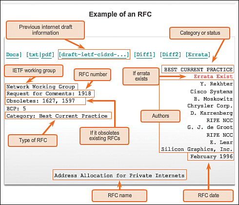
Some RFCs are not entirely new technologies or protocols, but instead are an update or extension of an existing RFC. In these cases, the RFC indicates in the header that it is an update and which RFC it is updating.
After an RFC has become an Internet standard, occasionally mistakes or errors are found. In these cases, an errata is created and the RFC includes “Errata Exist” in its header. Errata can be found in the RFC Editor site, http://www.rfc-editor.org/errata.php.
Lab 3.2.2.3: Researching RFCs
In this lab you will research RFCs and how they are published. You will also identify known RFCs used in your network.
Moving Data in the Network (3.3)
Communication across a network may require several steps and many different protocols to be successful. This section covers different elements of the communication process.
Data Encapsulation (3.3.1)
Information is added to data to enable network communication. The following sections explain how the added information assists in the communication process.
Elements of Communication (3.3.1.1)
Communication begins with a message, or information, that must be sent from one individual or device to another. People exchange ideas using many different communication methods. All of these methods have three elements in common:
![]() Message source (or sender): Message sources are people, or electronic devices, that need to send a message to other individuals or devices.
Message source (or sender): Message sources are people, or electronic devices, that need to send a message to other individuals or devices.
![]() Channel: A channel consists of the media that provides the pathway over which the message can travel from source to destination.
Channel: A channel consists of the media that provides the pathway over which the message can travel from source to destination.
![]() Message destination (or receiver): The message destination receives the message and interprets it.
Message destination (or receiver): The message destination receives the message and interprets it.
Consider, for example, the desire to communicate using words, pictures, and sounds. Each of these messages can be sent across a data or information network by first converting them into binary digits, or bits. These bits are then encoded into a signal that can be transmitted over the appropriate medium. In computer networks, the medium is usually a type of cable, or the atmosphere for a wireless transmission.
Video 3.3.1.1:
View the video in the online course for a demonstration of a communication process between two people. Click the second graphic to see the process between two devices over a network.
The term network in this course refers to data or information networks capable of carrying many different types of communications, including traditional computer data, interactive voice, video, and entertainment products.
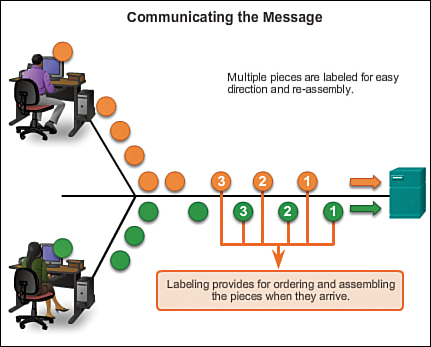
Communicating the Messages (3.3.1.2)
In theory, a single communication, such as a music video or an email message, could be sent across a network from a source to a destination as one massive, uninterrupted stream of bits. If messages were actually transmitted in this manner, it would mean that no other device would be able to send or receive messages on the same network while this data transfer was in progress. These large streams of data would result in significant delays. Further, if a link in the interconnected network infrastructure failed during the transmission, the complete message would be lost and would have to be retransmitted in full.
A better approach is to divide the data into smaller, more manageable pieces to send over the network. This division of the data stream into smaller pieces is called segmentation. Segmenting messages has two primary benefits:
![]() By sending smaller individual pieces from source to destination, many different conversations can be interleaved on the network. The process used to interleave the pieces of separate conversations together on the network is called multiplexing.
By sending smaller individual pieces from source to destination, many different conversations can be interleaved on the network. The process used to interleave the pieces of separate conversations together on the network is called multiplexing.
![]() Segmentation can increase the reliability of network communications. The separate pieces of each message need not travel the same pathway across the network from source to destination. If a particular path becomes congested with data traffic or fails, individual pieces of the message can still be directed to the destination using alternate pathways. If part of the message fails to make it to the destination, only the missing parts need to be retransmitted. Figure 3-7 depicts segments being multiplexed on a network.
Segmentation can increase the reliability of network communications. The separate pieces of each message need not travel the same pathway across the network from source to destination. If a particular path becomes congested with data traffic or fails, individual pieces of the message can still be directed to the destination using alternate pathways. If part of the message fails to make it to the destination, only the missing parts need to be retransmitted. Figure 3-7 depicts segments being multiplexed on a network.
Video 3.3.1.2:
View the video in the online course for a demonstration of segmentation and multiplexing.
The downside to using segmentation and multiplexing to transmit messages across a network is the level of complexity that is added to the process. Imagine if you had to send a 100-page letter, but each envelope would only hold one page. The process of addressing, labeling, sending, receiving, and opening the entire 100 envelopes would be time-consuming for both the sender and the recipient.
In network communications, each segment of the message must go through a similar process to ensure that it gets to the correct destination and can be reassembled into the content of the original message.
Various types of devices throughout the network participate in ensuring that the pieces of the message arrive reliably at their destination.
Protocol Data Units (PDUs) (3.3.1.3)
As application data is passed down the protocol stack on its way to be transmitted across the network media, various protocols add information to it at each level. This is commonly known as the encapsulation process.
The form that a piece of data takes at any layer is called a protocol data unit (PDU). During encapsulation, each succeeding layer encapsulates the PDU that it receives from the layer above in accordance with the protocol being used. At each stage of the process, a PDU has a different name to reflect its new functions. Although there is no universal naming convention for PDUs, in this course, the PDUs are named according to the protocols of the TCP/IP suite, as shown in Figure 3-8 (in the next section):
![]() Data: The general term for the PDU used at the application layer
Data: The general term for the PDU used at the application layer
![]() Segment: Transport layer PDU
Segment: Transport layer PDU
![]() Packet: Internet layer PDU
Packet: Internet layer PDU
![]() Frame: Network access layer PDU
Frame: Network access layer PDU
![]() Bits: A PDU used when physically transmitting data over the medium
Bits: A PDU used when physically transmitting data over the medium
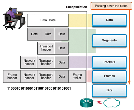
Encapsulation (3.3.1.4)
Data encapsulation is the process that adds additional protocol header information to the data before transmission. In most forms of data communications, the original data is encapsulated, or wrapped, in several protocols before being transmitted.
When sending messages on a network, the protocol stack on a host operates from top to bottom. In the web server example, we can use the TCP/IP model to illustrate the process of sending an HTML web page to a client.
The application layer protocol, HTTP, begins the process by delivering the HTML formatted web page data to the transport layer. There the application data is broken into TCP segments. Each TCP segment is given a label, called a header, containing information about which process running on the destination computer should receive the message. It also contains the information that enables the destination process to reassemble the data back to its original format.
The transport layer encapsulates the web page HTML data within the segment and sends it to the Internet layer, where the IP protocol is implemented. Here the entire TCP segment is encapsulated within an IP packet, which adds another label, called the IP header. The IP header contains source and destination host IP addresses, as well as information necessary to deliver the packet to its corresponding destination process.
Next, the IP packet is sent to the network access layer, where it is encapsulated within a frame header and trailer. Each frame header contains a source and destination physical address. The physical address uniquely identifies the devices on the local network. The trailer contains error checking information. Finally, the bits are encoded onto the media by the server network interface card (NIC). Figure 3-8 depicts the encapsulation process and how information is added to PDUs.
De-encapsulation (3.3.1.5)
The encapsulation process is reversed at the receiving host, and is known as de-encapsulation. De-encapsulation is the process used by a receiving device to remove one or more of the protocol headers. The data is de-encapsulated as it moves up the stack toward the end-user application.
Videos 3.3.1.4 and 3.3.1.5:
View the videos in the online course for a demonstration of encapsulation and de-encapsulation.
Activity 3.3.1.6: Identify the PDU Layer
Go to the online course and perform the PDU exercise.
Accessing Local Resources (3.3.2)
In this section you will learn about addressing data for delivery on the same network.
Network Addresses and Data Link Addresses (3.3.2.1)
The OSI model describes the processes of encoding, formatting, segmenting, and encapsulating data for transmission over the network. The network layer and data link layer are responsible for delivering the data from the source device or sender to the destination device or receiver. Protocols at both layers contain source and destination addresses, but their addresses have different purposes.
Network Address
The network layer, or Layer 3, logical address contains information required to deliver the IP packet from the source device to the destination device. A Layer 3 IP address has two parts, the network prefix and the host part. The network prefix is used by routers to forward the packet to the proper network. The host part is used by the last router in the path to deliver the packet to the destination device.
An IP packet contains two IP addresses:
![]() Source IP address: The IP address of the sending device.
Source IP address: The IP address of the sending device.
![]() Destination IP address: The IP address of the receiving device. The destination IP address is used by routers to forward a packet to its destination.
Destination IP address: The IP address of the receiving device. The destination IP address is used by routers to forward a packet to its destination.
Data Link Address
The data link, or Layer 2, physical address has a different role. The purpose of the data link address is to deliver the data link frame from one network interface to another network interface on the same network. Before an IP packet can be sent over a wired or wireless network, it must be encapsulated in a data link frame so it can be transmitted over the physical medium, the actual network. Ethernet LANs and wireless LANs are two examples of networks that have different physical media each with its own type of data link protocol.
The IP packet is encapsulated into a data link frame to be delivered to the destination network. The source and destination data link addresses are added (as shown a bit later in Figure 3-9.
![]() Source data link address: The physical address of the device that is sending the packet. Initially this is the NIC that is the source of the IP packet.
Source data link address: The physical address of the device that is sending the packet. Initially this is the NIC that is the source of the IP packet.
![]() Destination data link address: The physical address of the network interface of either the next hop router or the network interface of the destination device.
Destination data link address: The physical address of the network interface of either the next hop router or the network interface of the destination device.
Communicating with a Device on the Same Network (3.3.2.2)
To understand how communication is successful in the network, it is important to understand the roles of both the network layer addresses and the data link addresses when a device is communicating with another device on the same network.
Network Addresses
The network layer addresses, or IP addresses, indicate the network and host address of the source and destination. The network portion of the address will be the same; only the host or device portion of the address will be different.
![]() Source IP address: The IP address of the sending device, the client computer PC1: 192.168.1.110.
Source IP address: The IP address of the sending device, the client computer PC1: 192.168.1.110.
![]() Destination IP address: The IP address of the receiving device, FTP server: 192.168.1.9.
Destination IP address: The IP address of the receiving device, FTP server: 192.168.1.9.
Data Link Addresses
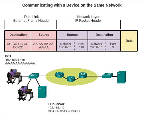
When the sender and receiver of the IP packet are on the same network, the data link frame is sent directly to the receiving device. On an Ethernet network, the data link addresses are known as Ethernet MAC addresses. MAC addresses are 48-bit addresses that are physically embedded on the Ethernet NIC. A MAC address is also known as the physical address or burned-in address (BIA). Refer to Figure 3-9 for the following example.
![]() Source MAC address: This is the data link address, or the Ethernet MAC address, of the device that sends the IP packet, PC1. MAC addresses are expressed in hexadecimal notation. The MAC address of the Ethernet NIC of PC1 is AA-AA-AA-AA-AA-AA.
Source MAC address: This is the data link address, or the Ethernet MAC address, of the device that sends the IP packet, PC1. MAC addresses are expressed in hexadecimal notation. The MAC address of the Ethernet NIC of PC1 is AA-AA-AA-AA-AA-AA.
![]() Destination MAC address: When the receiving device is on the same network as the sending device, this is the data link address of the receiving device. In this example, the destination MAC address is the MAC address of the FTP server: CC-CC-CC-CC-CC-CC.
Destination MAC address: When the receiving device is on the same network as the sending device, this is the data link address of the receiving device. In this example, the destination MAC address is the MAC address of the FTP server: CC-CC-CC-CC-CC-CC.
The source and destination addresses are added to the Ethernet frame. The frame with the encapsulated IP packet can now be transmitted from PC1 directly to the FTP server.
MAC and IP Addresses (3.3.2.3)
It should now be clear that to send data to another host on the same LAN, the source host must know both the physical and logical addresses of the destination host. When those are known, the source host can create a frame and send it out on the network media. The source host can learn the destination IP address in a number of ways. For example, it may learn the IP address through the use of the Domain Name System (DNS), or it may know the destination IP address because the address is entered in the application manually, such as when a user specifies the IP address of a destination FTP server. But how does a host determine the Ethernet MAC address of another device?
Most network applications rely on the logical IP address of the destination to identify the location of the communicating hosts. The data link MAC address is required to deliver the encapsulated IP packet inside the Ethernet frame across the network to the destination.
The sending host uses a protocol called Address Resolution Protocol (ARP) to discover the MAC address of any host on the same local network. The sending host sends an ARP Request message to the entire LAN. The ARP Request is a broadcast message. The ARP Request contains the IP address of the destination device. Every device on the LAN examines the ARP Request to see if it contains its own IP address. Only the device with the IP address contained in the ARP Request responds with an ARP Reply. The ARP Reply includes the MAC address associated with the IP address in the ARP Request.
Video 3.3.2.3:
View the video in the online course for a demonstration of the Address Resolution Protocol (ARP).
Accessing Remote Resources (3.3.3)
In this section you will learn about addressing data for delivery to remote networks.
Default Gateway (3.3.3.1)
The method that a host uses to send messages to a destination on a remote network differs from the way a host sends messages to a destination on the same local network. When a host needs to send a message to another host located on the same network, it will forward the message directly. A host will use ARP to discover the MAC address of the destination host. It includes the destination IP address within the packet header and encapsulates the packet into a frame containing the MAC address of the destination and forwards it.
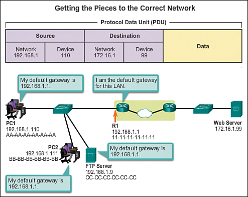
When a host needs to send a message to a remote network, it must use the router, also known as the default gateway. The default gateway is the IP address of an interface on a router on the same network as the sending host.
It is important that the address of the default gateway be configured on each host on the local network. If no default gateway address is configured in the host TCP/IP settings, or if the wrong default gateway is specified, messages addressed to hosts on remote networks cannot be delivered.
In Figure 3-10, the hosts on the LAN are using R1 as the default gateway with its 192.168.1.1 address configured in their TCP/IP settings. If the destination of a PDU is on a different IP network, the hosts send the PDUs to the default gateway on the router for further transmission.
Communicating with a Device on a Remote Network (3.3.3.2)
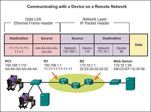
But what are the roles of the network layer addresses and the data link layer addresses when a device is communicating with a device on a remote network? Figure 3-11 is an example in which we have a client computer, PC1, communicating with a server, named Web Server, on a different IP network.
Network Addresses
IP addresses indicate the network and device addresses of the source and destination. When the sender of the packet is on a different network from the receiver, the source and destination IP addresses will represent hosts on different networks. This will be indicated by the network portion of the IP address of the destination host.
![]() Source IP address: The IP address of the sending device, the client computer PC1: 192.168.1.110.
Source IP address: The IP address of the sending device, the client computer PC1: 192.168.1.110.
![]() Destination IP address: The IP address of the receiving device, the server, Web Server: 172.16.1.99.
Destination IP address: The IP address of the receiving device, the server, Web Server: 172.16.1.99.
Data Link Addresses
When the sender and receiver of the IP packet are on different networks, the Ethernet data link frame cannot be sent directly to the destination host because the host is not directly reachable in the network of the sender. The Ethernet frame must be sent to another device, known as the router or default gateway. In our example in Figure 3-11, the default gateway is R1. R1 has an interface and an IP address that is on the same network as PC1. This allows PC1 to reach the router directly.
![]() Source MAC address: The Ethernet MAC address of the sending device, PC1. The MAC address of the Ethernet interface of PC1 is AA-AA-AA-AA-AA-AA.
Source MAC address: The Ethernet MAC address of the sending device, PC1. The MAC address of the Ethernet interface of PC1 is AA-AA-AA-AA-AA-AA.
![]() Destination MAC address: When the receiving device is on a different network from the sending device, this is the Ethernet MAC address of the default gateway or router. In this example, the destination MAC address is the MAC address of the R1 Ethernet interface that is attached to the PC1 network, which is 11-11-11-11-11-11.
Destination MAC address: When the receiving device is on a different network from the sending device, this is the Ethernet MAC address of the default gateway or router. In this example, the destination MAC address is the MAC address of the R1 Ethernet interface that is attached to the PC1 network, which is 11-11-11-11-11-11.
The Ethernet frame with the encapsulated IP packet can now be transmitted to R1. R1 forwards the packet to the destination, Web Server. This may mean that R1 forwards the packet to another router or directly to Web Server if the destination is on a network connected to R1.
How does the sending device determine the MAC address of the router?
Each device knows the IP address of the router through the default gateway address configured in its TCP/IP settings. The default gateway address is the address of the router interface connected to the same local network as the source device. All devices on the local network use the default gateway address to send messages to the router. After the host knows the default gateway IP address, it can use ARP to determine the MAC address of that default gateway. The MAC address of the default gateway is then placed in the frame.

Packet Tracer Activity 3.3.3.3: Explore a Network
This simulation activity is intended to help you understand the flow of traffic and the contents of data packets as they traverse a complex network. Communications will be examined at three different locations simulating typical business and home networks.
Lab 3.3.3.4: Using Wireshark to View Network Traffic
In this lab you will download and install Wireshark, then use the application to capture and analyze local and remote data.
Summary (3.4)
Class Activity 3.4.1.1: Guaranteed to Work!
Go to the online course to perform the communication activity in which you compare results from the modeling activity at the beginning of this chapter to the networking models used for communications.
Data networks are systems of end devices, intermediary devices, and the media connecting the devices. For communication to occur, these devices must know how to communicate.
These devices must comply with communication rules and protocols. TCP/IP is an example of a protocol suite. Most protocols are created by a standards organization such as the IETF or IEEE. IEEE is a professional organization for those in the electrical engineering and electronics fields. ISO, the International Organization for Standardization, is the world’s largest developer of international standards for a variety of products and services.
The most widely used networking models are the OSI and TCP/IP models. Associating the protocols that set the rules of data communications with the different layers of these models is useful in determining which devices and services are applied at specific points as data passes across LANs and WANs.
Data that passes down the stack of the OSI model is segmented into pieces and encapsulated with addresses and other labels. The process is reversed as the pieces are de-encapsulated and passed up the destination protocol stack. The OSI model describes the processes of encoding, formatting, segmenting, and encapsulating data for transmission over the network.
The TCP/IP protocol suite is an open standard protocol that has been endorsed by the networking industry and ratified, or approved, by a standards organization. The IP suite is a suite of protocols required for transmitting and receiving information using the Internet.
PDUs are named according to the protocols of the TCP/IP suite: data, segment, packet, frame, and bits.
Applying models allows individuals, companies, and trade associations to analyze current networks and plan the networks of the future.
Practice
The following activities provide practice with the topics introduced in this chapter. The Labs and Class Activities are available in the companion Network Basics Lab Manual (978-1-58713-313-8). The Packet Tracer Activities PKA files are found in the online course.
Class Activities
Class Activity 3.0.1.2: Designing a Communications System
Class Activity 3.4.1.1: Guaranteed to Work!
Labs
Lab 3.1.3.6: Researching Networking Standards
Lab 3.2.2.3: Researching RFCs
Lab 3.3.3.4: Using Wireshark to View Network Traffic
Packet Tracer Activities
Packet Tracer Activity 3.1.4.6: Investigating the TCP/IP and OSI Models in Action
Packet Tracer Activity 3.3.3.3: Explore a Network
Check Your Understanding
Complete all the review questions listed here to test your understanding of the topics and concepts in this chapter. The appendix, “Answers to the ‘Check Your Understanding’ Questions,” lists the answers.
1. Which is not a common networking protocol?
A. DHCP
B. IP
C. IPHD
D. HTTP
2. When multiple protocols interact to perform functions, it is considered to be which of the following?
A. A protocol suite (also known as a protocol stack)
B. A proprietary protocol
C. An open standard protocol
D. A routing protocol
3. Which of the following groups develop protocol standards? (Choose three.)
A. IEEE
B. EAEIO
C. IETF
D. AITU
E. ITU-T
F. SIOIT
4. What of the following provides descriptions of tasks that need to be accomplished by protocols in layers?
A. A protocol suite
B. A protocol model
C. A reference model
D. A protocol stack
5. The TCP/IP application layer consists of which three OSI layers?
A. Application, session, transport
B. Application, presentation, network access
C. Application, presentation, session
D. Application, transport, data link
6. Choose two reasons networking standards are used.
A. Standards provide a way for consistent development of technologies at each level.
B. Standards have eliminated the use of proprietary protocols.
C. Standards allow equipment from different companies a common format for communication.
D. Standards reduce competition so that fewer vendors can control the development of protocols.
7. The application layer is ___________ of the OSI model.
A. Layer 1
B. Layer 3
C. Layer 4
D. Layer 7
8. A technician responds to a complaint that a computer will not connect to the Internet. He soon realizes the IP address is on a different network. Which layer of the OSI model describes this problem?
A. Layer 2
B. Layer 3
C. Layer 4
D. Layer 7
9. Which OSI layer is responsible for exchanging frames between network devices?
A. Layer 1
B. Layer 2
C. Layer 3
D. Layer 4
10. A technician responds to a complaint that a computer will not connect to the Internet. She soon realizes the computer’s Ethernet cable has accidently been cut during a move. Which layer of the OSI model describes this problem?
A. Layer 1
B. Layer 2
C. Layer 3
D. Layer 4
11. Which layers of the OSI model combine to make the network access layer of the TCP/IP model?
A. Data link and network
B. Layers 5 and 6
C. Layers 3 and 4
D. Data link and physical
12. The numbered documents that specify networking standards and protocols are known as
A. RFCs
B. IPXs
C. IETFs
D. IMP Statements
13. Which protocol data unit is not correctly matched to its TCP/IP layer? (Choose two.)
A. Bits: Application layer PDU
B. Segment: Transport layer PDU
C. Packet: Network access layer PDU
D. Frame: Network access layer PDU
14. When an Ethernet frame arrives at its destination, the computer must ______ the frame.
A. Encapsulate
B. Un-frame
C. Segment
D. De-encapsulate
15. Which of the following is true of packet PDUs? (Choose two.)
A. They contain destination IP addresses.
B. They contain source MAC addresses.
C. They contain timing bits.
D. They contain source IP addresses.
E. They contain destination MAC addresses.
16. Which of the following is true of Ethernet frame PDUs? (Choose two.)
A. They contain destination IP addresses.
B. They contain source MAC addresses.
C. They contain timing bits.
D. They contain source IP addresses.
E. They contain destination MAC addresses.