Chapter 7. Implementing Cisco Unified Communications Manager Call Routing and Digit Manipulation
Call routing enables users to reach destinations (numbers/URIs) within and outside of the organization. The process of call routing uses a number of elements as Cisco Unified Communications Manager (CUCM) attempts to determine the feasibility and the final destination of the call. Ultimately it comes down to one of two call types. The call will be routed to an internal number, such as a directory number (DN) of an endpoint or a feature number such as a Meet-Me conference, or the call will be routed via a route pattern through a gateway or trunk for delivery outside the cluster. Endpoint addressing is an important component of a dial plan and mandatory for the routing of internal calls and external calls. Call routing includes a number of components and works in a very hierarchical fashion.
For calls going out of an organization, there are various requirements about the way the calling party or the called party numbers are presented; and this is achieved by digit manipulation in CUCM. CUCM supports a host of digit manipulation mechanisms suited to various requirements and design specifics. Both call routing and digit manipulation work hand-in-hand for successful call placement—both internally and externally in a Cisco Collaboration solution.
This chapter explains the call routing implementation in CUCM, and covers the concept of digit manipulation in CUCM.
Chapter Objectives
Upon completing this chapter you will be able to meet the following objectives:
![]() Describe how to implement directory numbers and URIs.
Describe how to implement directory numbers and URIs.
![]() Define call routing and list sources and targets of calls.
Define call routing and list sources and targets of calls.
![]() Describe the call routing logic in Cisco Unified Communications Manager.
Describe the call routing logic in Cisco Unified Communications Manager.
![]() Describe the components that enable call routing in Cisco Unified Communications Manager.
Describe the components that enable call routing in Cisco Unified Communications Manager.
![]() Describe addressing methods, and explain how Cisco Unified Communications Manager analyzes received digits.
Describe addressing methods, and explain how Cisco Unified Communications Manager analyzes received digits.
![]() Describe the post-dial delay of variable-length patterns and overlapping patterns, and explain how to solve this problem.
Describe the post-dial delay of variable-length patterns and overlapping patterns, and explain how to solve this problem.
![]() Describe the various mechanisms in Cisco Unified Communications Manager that allow digit manipulation.
Describe the various mechanisms in Cisco Unified Communications Manager that allow digit manipulation.
![]() Describe the implementation of digit manipulation mechanisms such as transformation mask, translation patterns, significant digits, transformation patterns, and prefixing or discarding digits in digit manipulation.
Describe the implementation of digit manipulation mechanisms such as transformation mask, translation patterns, significant digits, transformation patterns, and prefixing or discarding digits in digit manipulation.
Endpoint Addressing
One of the fundamental steps in defining a dial plan for call routing is to identify the Cisco Unified IP Phones, Cisco Jabber endpoints, or Cisco Telepresence endpoints that will be associated with a cluster.
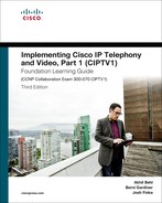
When CUCM was first designed, Session Initiation Protocol (SIP) was not supported for endpoint registration. SIP support to the phones was first introduced in CUCM release 5.0. One of the benefits that SIP brings is the ability to dial using a name instead of a number. The phones were originally configured only with directory numbers (DNs). Once SIP was introduced, the logical way to implement the name-based calling feature was to map the name, referred to as the URI, to the existing DN. This section describes how to implement directory numbers and directory URIs. Figure 7-1 shows endpoints and addressing, both in DN and URI formats.
In order to reach internal endpoints (such as IP phones or fax machines) and applications (such as voicemail systems, auto-attendants, and conferencing systems), you must assign at least one directory number to each element. In addition, you can assign directory URIs as aliases to directory numbers. By calling a configured directory number or directory URI, you can reach the corresponding device within or outside the organization, provided the dial plan is complete and the route to the destination is known by call-control.
Endpoint Addressing by Numbers
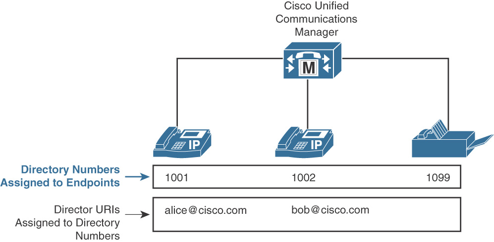
This section describes what you need to consider when implementing endpoint addressing by numbers. Figure 7-2 illustrates directory numbers and E.164 numbering format considerations.
Note
E.164 and +E.164 numbering plans were reviewed in Chapter 6, “Dial Plan Design and Implementation in Cisco Unified Communications Manager.” A detailed look at this topic is provided in Implementing Cisco IP Telephony and Video, Part 2 (CIPTV2).
Note
Dial plan and numbering plan setup needs immaculate planning and can initially be time consuming. However, the longer terms benefits of having a well-designed dial/numbering plan are invaluable.
First, plan the length of the internally used extension. Depending on the number of required extensions, you may choose longer or shorter extensions. With four-digit extensions, you can theoretically address up to 10,000 endpoints. In reality, this number will be smaller because some leading digits, such as 0 or 9, are used as operator or external line access codes, so they should not be used as the leading digits of an extension.
Typically, the phones should also be reachable from the public switched telephone network (PSTN). You can call internal endpoints from the outside in two ways:
![]() Two-stage dialing: With two-stage dialing, all endpoints share a single PSTN number. When a PSTN user wants to call an internal endpoint, they call the PSTN number of the target company. The communications system (for example, CUCM) accepts the call either by routing the call to the extension of an operator or receptionist or by answering the call with an auto-attendant IVR script that allows the caller then to enter the extension of the desired internal user or to use a dial-by-name search feature.
Two-stage dialing: With two-stage dialing, all endpoints share a single PSTN number. When a PSTN user wants to call an internal endpoint, they call the PSTN number of the target company. The communications system (for example, CUCM) accepts the call either by routing the call to the extension of an operator or receptionist or by answering the call with an auto-attendant IVR script that allows the caller then to enter the extension of the desired internal user or to use a dial-by-name search feature.
![]() Direct inward dialing (DID): With DID, each internal phone has its own PSTN number. Ideally, the least significant digits of the external DID range match the internally used extension numbers (1:1 mapping). If a corresponding DID range is not available and your PSTN provider assigns different external numbers, you must map each external number to an internal extension and translate the number accordingly. In other countries, this service may be referred to as direct dial-in (DDI).
Direct inward dialing (DID): With DID, each internal phone has its own PSTN number. Ideally, the least significant digits of the external DID range match the internally used extension numbers (1:1 mapping). If a corresponding DID range is not available and your PSTN provider assigns different external numbers, you must map each external number to an internal extension and translate the number accordingly. In other countries, this service may be referred to as direct dial-in (DDI).
The E.164 number format is used in the PSTN environment. E.164 numbers start with a country code and can have a maximum of 15 digits. Globally unique phone numbers are usually written with a plus sign (+) before the phone number to indicate that the number is in international (E.164) format. In Cisco documentation, such numbers are referred to as +E.164 numbers.
To actually dial a PSTN number from a normal fixed-line phone, it may be necessary to use the appropriate access code. Every country has both a national access code, which is used to dial a long-distance number, and an international access code, which is used to dial out of the country. To indicate that a call should be sent to the PSTN instead of being routed within the enterprise, a PSTN access code may be dialed first.
As illustrated in Figure 7-2, the four-digit internal directory numbers are mapped 1:1 to external E.164 numbers.
Dial plan design may dictate that all internal numbers be in the +E.164 number format. This is often the case for global companies or for companies that use certain features that benefit from +E.164 number formats, such as local route groups with device mobility.
In cases where a +E.164 dial plan is implemented, directory numbers may also be in the + format; for example, the DN for a phone may be configured as +19025550123. All other numbers defined in the dial plan, such as Meet-Me numbers, route patterns, etc., would also be defined using the + format. This does not necessarily mean that you have to dial the entire string of numbers when you call your colleague across the hall. You may still be able to dial the five-digit extension of 50123, and the CUCM can have a translation pattern configured to change the 50123 dialed digits to +19025550123, which will now match the configured DN of your colleague’s phone.
One significant benefit of +E.164 dial plan formats is that users can dial numbers in their locally known formats and CUCM will convert digit strings into +E.164 format prior to performing dial plan lookup. This is referred to as normalizing the number into a global format.
Once the call matches a route pattern determining which gateway or trunk is used to deliver the call, CUCM then localizes the number, changing it back to the locally known format of the gateway or trunk that will process the call.
Endpoint Addressing by URIs
This section describes how to place calls using a URI.
Directory URIs are aliases to directory numbers. Directory URIs are not assigned to a phone line but are assigned to a directory number (which is assigned to a phone line). A directory URI is also known as an SIP URI.
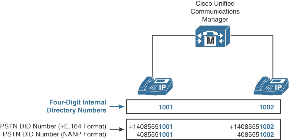
The format of a URI is (user portion)@(host portion), so a URI most often looks like an e-mail address. The host portion can be a domain name or an IP address. You can place calls to URIs from endpoints that support URI dialing by dialing a fully qualified URI or by dialing only the user portion. If you place a call to a URI that is not fully qualified, then CUCM appends the configured Organizational Top Level Domain (OTLD) enterprise parameter to complete the URI. For example, if the OTLD is set for cisco.com and a user simply makes a call to Alice, then CUCM appends the OTLD to create a URI in the form of [email protected]
Note
URI addressing is most common in the video world. It’s been there for many years, and Cisco Collaboration 10.x supports SIP URI for video and audio communications with most endpoints.
Ideally, all URIs that are applied to endpoints of a CUCM cluster use the same, globally unique host portion. If you use the same host portion in different clusters, calls between these clusters work only if you implement URI synchronization. URI synchronization among clusters is provided by Intercluster Lookup Service (ILS) and Global Dial Plan Replication (GDPR). ILS and GDPR are covered in detail in Implementing Cisco IP Telephony and Video, Part 2 (CIPTV2).
URIs are not directly applied to a phone or phone line, but they are associated with a directory number. When a call is placed to a locally configured URI, CUCM routes the call to the associated directory number.
The user portion of a directory URI is case sensitive. You can change the user portion to be case insensitive by setting the enterprise parameter URI Lookup Policy to Case Insensitive. The host portion is always case insensitive.
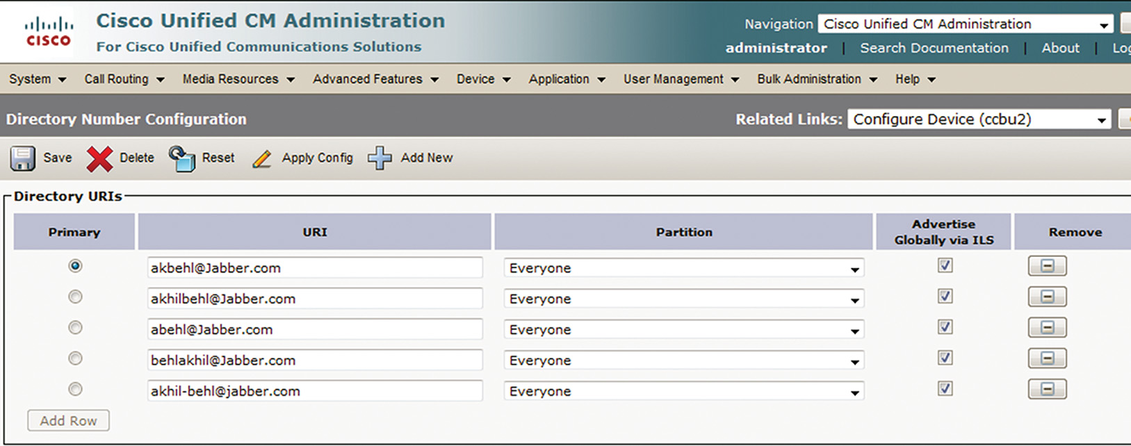
Figure 7-3 shows Jabber client with URI addressing.
CUCM allows defining up to five URIs for every DN defined as shown in Figure 7-4.
The next section covers CUCM-based call routing.
Cisco Unified Communications Manager Call Routing Overview
This section defines call routing and lists sources and targets of calls.
Calls must be routed and interconnected according to the dialed number or URI. Like IP routing, call routing is, by default, destination-based routing. There are three main types of call routing:
![]() Intrasite routing: This type of call routing occurs within a single site.
Intrasite routing: This type of call routing occurs within a single site.
![]() Intersite routing: This type of call routing type occurs between multiple sites.
Intersite routing: This type of call routing type occurs between multiple sites.
![]() On net: Calls between sites are usually sent over the WAN. Translation patterns can be used to change the format of the called number or the caller id if sites use access codes and site codes to differentiate DNs per site.
On net: Calls between sites are usually sent over the WAN. Translation patterns can be used to change the format of the called number or the caller id if sites use access codes and site codes to differentiate DNs per site.
![]() Off net: Calls between sites can be routed over the PSTN if routing over the WAN does not succeed. In this case, digit manipulation is required to change the DN to a PSTN routable number. A route pattern is then used to determine where and how the call is sent to the PSTN.
Off net: Calls between sites can be routed over the PSTN if routing over the WAN does not succeed. In this case, digit manipulation is required to change the DN to a PSTN routable number. A route pattern is then used to determine where and how the call is sent to the PSTN.
![]() External routing: Calls to numbers that are not locally defined in the CUCM cluster are routed by matching a route pattern. A route pattern points to the way out of the cluster, either directly through a gateway or trunk or by using the route list > route group > gateway/trunk construct.
External routing: Calls to numbers that are not locally defined in the CUCM cluster are routed by matching a route pattern. A route pattern points to the way out of the cluster, either directly through a gateway or trunk or by using the route list > route group > gateway/trunk construct.
Figure 7-5 gives an overview of call routing in a typical enterprise network.
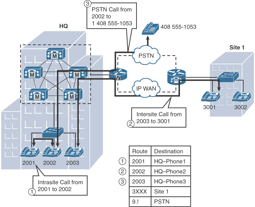
As seen in Figure 7-5, at HQ the extensions are 2XXX from 2001 to 2003, whereas at Site 1 the extensions are 3XXX, ranging from 3001 to 3002. Any call within the 2XXX dialing domain is an intrasite call, and similarly any call within the 3XXX dialing domain is also an intrasite call. On the other hand, a call between 2XXX and 3XXX or vice versa is an intersite call. Any call outside of the 2XXX and 3XXX dialing domains is an external call going via the gateway to the PSTN (traditional trunk or IP telephony service provider (ITSP) SIP trunk).
CUCM can automatically route calls to internal destinations within the same cluster because CUCM is aware of the configured directory numbers of its associated devices. This scenario can be compared to networks that are directly connected at a router IP routing.
Note
The CUCM call routing database includes the directory numbers of Cisco IP phones and various devices configured in the CUCM cluster. CUCM, however, is not aware of any numbers not explicitly configured and of the devices not registered/configured in the CUCM cluster.
For external destinations, an explicit route—called a route pattern—must be configured. External destinations are PSTN destinations (including off net intersite calls, which are effectively PSTN destinations because they are addressed by their PSTN numbers), other voice over IP (VoIP) domains such as an IP telephony service provider, or another CUCM cluster. A route pattern is equivalent to a static route in an IP router.
To route calls to numbers outside the cluster, the CUCM call routing must match route patterns that point to external destinations.
Regardless of the call routing type, the call routing process itself can be summarized as shown in the following steps:
Step 1. CUCM receives a call setup request from a local endpoint or from another call control system, such as a remote CUCM cluster, Cisco Unified Communications Manager Express, or a PSTN gateway.
Step 2. CUCM analyzes the target of the received request to find the best matching entry in its call routing table. The type of analysis depends on the addressing method that is used by the source of the call setup request (digit-by-digit or en bloc) and the address type (number versus URI). Digit-by-digit and en bloc dialing methods are covered in more detail later in this chapter.
Step 3. CUCM forwards the call setup request to the destination device that is associated with the matched call routing table entry. This destination device can be a local endpoint or another remote call control system.
Sources of Call Routing Requests (Entities Requiring Call Routing Table Lookups)
There are a number of elements that are considered sources of call routing requests. Some, such as IP phones, are an obvious example. Others are not so noticeable. The following list describes sources of call routing requests:
![]() Cisco Unified IP Phones, Jabber, or analog phones/endpoints: when a call is dialed from a phone, CUCM considers the phone as the source of the request.
Cisco Unified IP Phones, Jabber, or analog phones/endpoints: when a call is dialed from a phone, CUCM considers the phone as the source of the request.
![]() Gateways and trunks: Gateways and trunks connect the cluster to other clusters, other call processing systems, and to the PSTN or a SIP service provider. When a call comes into the cluster through a trunk or gateway, the CUCM treats the gateway or trunk as the source of the call.
Gateways and trunks: Gateways and trunks connect the cluster to other clusters, other call processing systems, and to the PSTN or a SIP service provider. When a call comes into the cluster through a trunk or gateway, the CUCM treats the gateway or trunk as the source of the call.
![]() Translation patterns: Translation patterns are almost identical to route patterns, with a couple of notable exceptions. First, a translation pattern can have a null string as the pattern which can be used to configure Private Line Auto Ringdown (PLAR). Second, a route pattern points to a way out of the cluster, while the translation pattern does not. The only role of a translation pattern is to match a dialed destination, change something about the calling or called number, and send the call back for another call routing lookup. At this point, to CUCM, it looks like the translation pattern is the source of the call.
Translation patterns: Translation patterns are almost identical to route patterns, with a couple of notable exceptions. First, a translation pattern can have a null string as the pattern which can be used to configure Private Line Auto Ringdown (PLAR). Second, a route pattern points to a way out of the cluster, while the translation pattern does not. The only role of a translation pattern is to match a dialed destination, change something about the calling or called number, and send the call back for another call routing lookup. At this point, to CUCM, it looks like the translation pattern is the source of the call.
![]() Voicemail ports: A voicemail system, such as Cisco Unity Connection, allows callers to initiate calls as well as leave voicemail. When a caller dials an extension while in Unity Connection, the call is passed from Unity Connection to CUCM via voicemail ports if the integration is based on Skinny Client Control Protocol (SCCP). To CUCM, it looks as if the voicemail port is the source of the call.
Voicemail ports: A voicemail system, such as Cisco Unity Connection, allows callers to initiate calls as well as leave voicemail. When a caller dials an extension while in Unity Connection, the call is passed from Unity Connection to CUCM via voicemail ports if the integration is based on Skinny Client Control Protocol (SCCP). To CUCM, it looks as if the voicemail port is the source of the call.
Note
The distinction between call routing sources and call routing targets is important when implementing features such as calling privileges, call classification, and others.
Call Routing Table Entries (Call Routing Targets)
This section describes call routing table entries, also called call routing targets.
The CUCM call routing table is composed of directory numbers, route patterns, translation patterns, and other entries. The list below shows some examples of call routing table entries.
![]() Directory numbers: Assigned to endpoints such as Cisco Unified IP Phones, Cisco IP Communicator, etc.
Directory numbers: Assigned to endpoints such as Cisco Unified IP Phones, Cisco IP Communicator, etc.
![]() Directory URIs: Assigned to directory numbers. URIs are associated with a DN rather than a physical or logical device.
Directory URIs: Assigned to directory numbers. URIs are associated with a DN rather than a physical or logical device.
![]() Translation patterns: Used to match a dialed number, change something about the calling or called number, and send it back for another call routing table lookup based on the changed number.
Translation patterns: Used to match a dialed number, change something about the calling or called number, and send it back for another call routing table lookup based on the changed number.
![]() Route patterns/SIP route patterns: Used to route calls to off-net destinations such as the PSTN or other CUCM clusters. Route patterns typically point to a route list, which contains one or more route groups, each of which can contain one or more gateways or trunks.
Route patterns/SIP route patterns: Used to route calls to off-net destinations such as the PSTN or other CUCM clusters. Route patterns typically point to a route list, which contains one or more route groups, each of which can contain one or more gateways or trunks.
![]() Hunt pilot: Used to route calls to line group members based on a distribution algorithm
Hunt pilot: Used to route calls to line group members based on a distribution algorithm
![]() Call Park numbers: Used to place a call on hold and retrieve the same call from another phone by dialing the call park number
Call Park numbers: Used to place a call on hold and retrieve the same call from another phone by dialing the call park number
![]() Meet-Me numbers: Used by a conference initiator to initiate a conference by pressing the Meet-Me soft key and dialing the conference number, while all other participants simply dial the same conference number
Meet-Me numbers: Used by a conference initiator to initiate a conference by pressing the Meet-Me soft key and dialing the conference number, while all other participants simply dial the same conference number
These entries are all possible call routing targets. If a dialed number matches one of these entries, the call is routed to the appropriate entity. That entity can be a phone line, a trunk, a gateway, a feature, or an application.
For SIP URI–based call routing, only directory URIs and SIP route patterns are applicable. All other examples refer to call routing for numbered targets. However, calls placed to directory URIs can only be routed to a local phone if the directory URI is associated with a directory number. Otherwise, calls to a directory URI will attempt to match a SIP route pattern to determine the location of the receiving endpoint.
Dialing Methods and Digit Analysis
This section describes addressing methods and explains how CUCM analyzes received digits.
Table 7-1 shows the addressing methods that CUCM supports for different devices. Keypad Markup Language (KPML) is a standards-based mechanism that allows SIP phones to provide a digit-by-digit dial experience for SIP phones.
Table 7-1 Addressing Methods
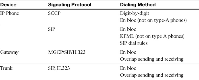
Digit-by-digit dialing is achieved when the caller first goes off-hook, hears the dial tone, and then begins to dial the digits. With digit-by-digit dialing, CUCM evaluates dial plan matches after each digit dialed. Therefore, as you dial a number, once you dial enough digits for CUCM to recognize that the number doesn’t exist or you do not have permission to dial that number, it presents a fast busy signal at that digit. If you hear a fast busy partway through dialing a number, that may give you a clue as to what to check when you are troubleshooting.
En bloc dialing is achieved when the caller does not go off-hook but first dials all the required digits and then goes off-hook or presses the dial soft key. All the digits are sent to CUCM at the same time, and CUCM compares the entire string against the dial plan to determine reachability. It is possible to get a different result for a call by dialing digit-by-digit versus en bloc.
SCCP phones support both digit-by-digit and en bloc dialing. Figure 7-6 illustrates an SCCP phone dialing 1000.
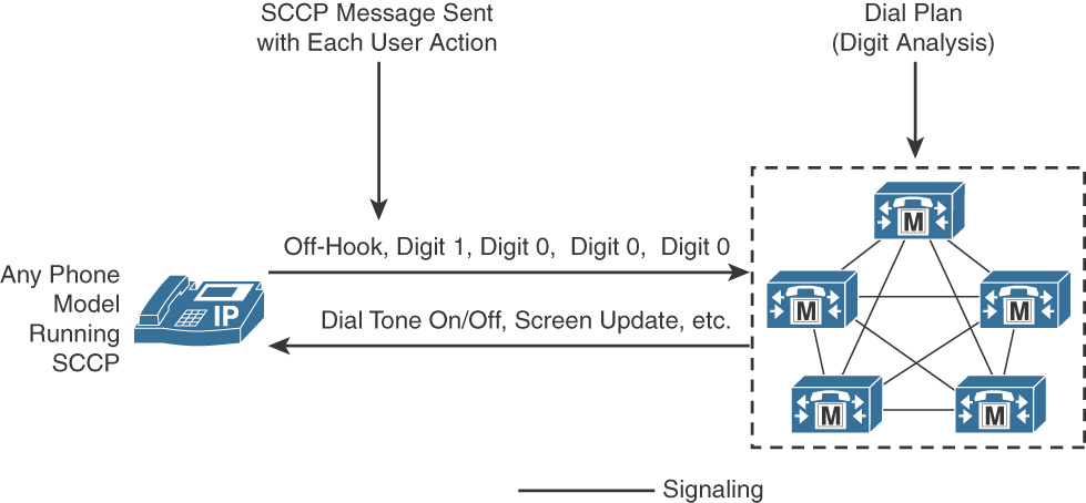
Note
Skinny Client Control Protocol (SCCP) is a stimulus/response protocol in which the endpoint sends user input (stimulus) and expects some type of response from the call-control server (CUCM) instructing the endpoint about what to do.
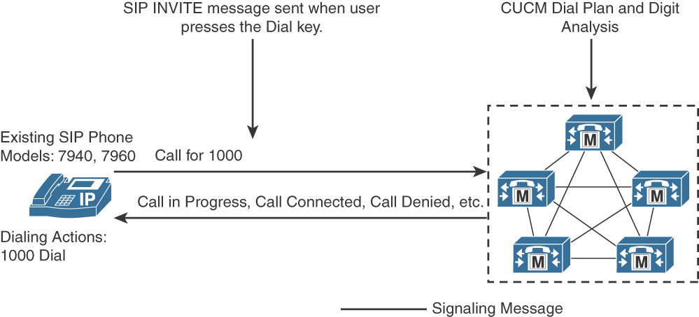
In SIP, you can use en bloc dialing or Keypad Markup Language (KPML). In en bloc dialing, the whole dialed string is sent in a single SIP INVITE message. KPML provides the digit-by-digit dial experience for SIP phones. KPML allows digits to be sent one by one. If you have configured SIP dial rules for the SIP phone, they are processed inside the SIP phone as the user dials. Therefore, a SIP phone can detect invalid numbers and play a reorder tone, without sending any signaling messages to CUCM. If dialed digits match an entry of a SIP dial rule, the dialed string is sent in a single SIP INVITE message to CUCM. If CUCM requires more digits, KPML can be used to send the remaining digits one by one, from the SIP phone to CUCM.
Older SIP phones (Type A), such as 7905, 7912, 7940, and 7960 models, support SIP dial rules but do not support KPML. Newer SIP phone models and Type B phones, for example 79×1, 79×2, 79×5, and 7970 models, support both dial rules and KPML. If a phone model supports KPML, it is on by default. Dial rules are optional elements for SIP phones. Figure 7-7 shows the signaling interaction between a Type A SIP Phone and CUCM when no dial rules have been configured.
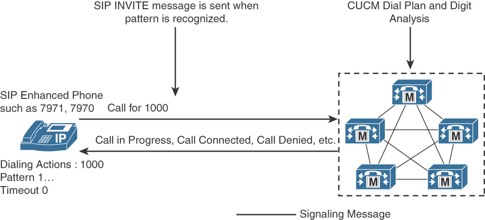
Type B phones and newer models support KPML and SIP dial rules. KPML is the default dialing behavior. However, if SIP dial rules are configured, KPML is disabled, and dial rules are used for call processing. In this case, the SIP phone provides local dial tone and processes dialed digits against the internal SIP dial rules before issuing a SIP INVITE message to CUCM.
Figure 7-8 illustrates signal processing for a Type B phone with dial rules configured. This process is the same for either Type A or Type B phones.
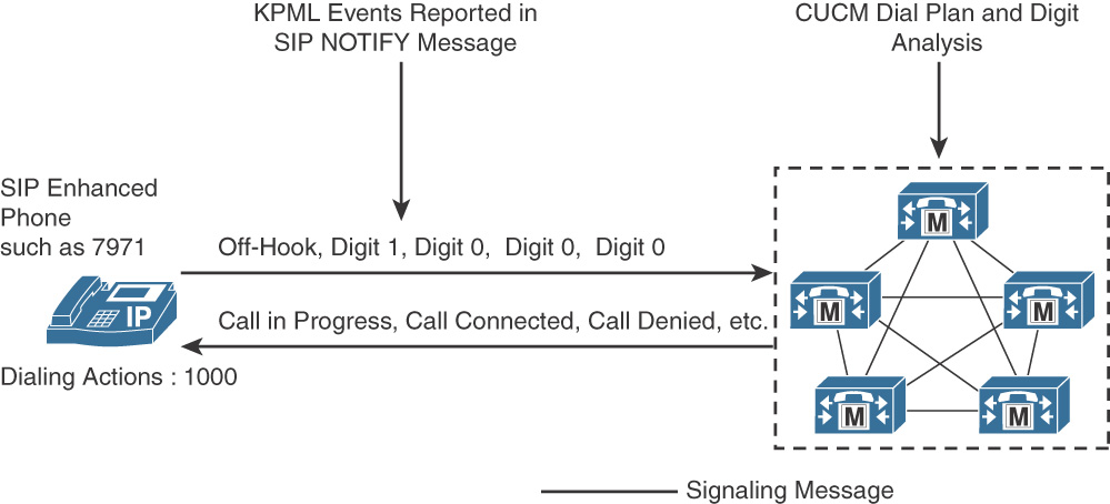
For Type B and newer phone models, KPML is the default signaling method. Figure 7-9 illustrates the use of SIP NOTIFY messages to convey each individual keypress from the phone to CUCM. For more information on this process, please refer to RFC 4730.
Trunks, such as SIP or H.323 trunks, and ISDN Primary Rate Interface (PRI) can be configured for overlap sending and receiving, allowing digits to be sent or received one by one. This may be required to be configured within countries that have variable length numbering plans.
Note
Voice gateway and Cisco Unified Border Element (CUBE) dial plan is discussed in detail in Chapter 13, “Implementing Cisco IOS Voice Gateways and Cisco Unified Border Element.”
In summary, CUCM supports both digit-by-digit dialing and en bloc dialing. The method used is dependent on the device and the protocol used.
Digit-by-Digit Analysis of Numbers Not Received In a Single Block
When CUCM does not receive all dialed digits at once (the en bloc addressing method is not used), then CUCM analyzes the digits as they are received. Figure 7-10 shows the matching logic utilized for digit analysis.
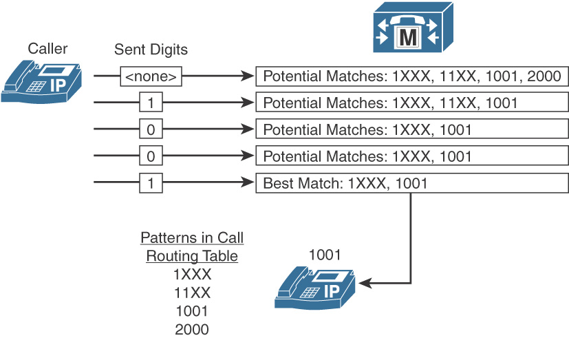
Be aware that if a phone sends dialed digits one by one, CUCM begins digit analysis immediately upon receiving the first digit. In fact, digit analysis starts one step earlier, when a phone indicates an off-hook state to CUCM. At that point, CUCM looks up a null string dialed number that matches all available call routing tables or may match a null string defined in a translation pattern in support of Private Line Automatic Ringdown (PLAR).
By analyzing each additional digit that is received, CUCM reduces the list of potential matches (that is, the call routing table entries that match the digits that have been received so far). After a single entry is matched, such as the directory number 1001 in Figure 7-10, the call is sent to the corresponding device.
Note
CUCM does not always receive dialed digits one by one. SCCP phones support digit-by-digit dialing and can be configured to support en bloc dialing. SIP phones can use en bloc dialing to send the whole dialed string at once or can use KPML to send the string digit-by-digit. If digits are received en bloc, the whole received dial string is checked at once against the call routing table.
Variable-Length Patterns, Overlapping Patterns, and Urgent Priority
This section describes the postdial delay of variable-length patterns and overlapping patterns and explains how to solve this problem. The interdigit timer (T302 timer) plays a role in determining the length of time CUCM will wait to complete the call whenever multiple matching patterns contain a different number of matching digits.
Variable-Length Patterns and Interdigit Timeout
International destinations are usually configured by using the exclamation point (!) wildcard, which represents any quantity of digits (that is, variable-length patterns). For example, in North America, the route pattern 9.011! is typically configured for international calls. In most European countries, the same result is accomplished by using the 0.00! route pattern.
When matching a variable-length pattern, CUCM does not know when dialing is complete and waits for the T302 timer to expire (15 seconds by default) before processing the call. This postdial delay can be reduced or eliminated as follows:
![]() Reduce the T302 timer (this timer is a Cisco CallManager service parameter) to allow earlier detection of the end of dialing. However, do not set this timer to less than 4 seconds, to prevent premature transmission of the call before the user finishes dialing.
Reduce the T302 timer (this timer is a Cisco CallManager service parameter) to allow earlier detection of the end of dialing. However, do not set this timer to less than 4 seconds, to prevent premature transmission of the call before the user finishes dialing.
![]() Configure a second route pattern, followed by the pound sign (#) wildcard (for example, 9.011!# for North America or 0.00!# for Europe), and let users know that they can indicate end of dialing by terminating the number with the # key. This action is analogous to pressing the Send button on a cell phone.
Configure a second route pattern, followed by the pound sign (#) wildcard (for example, 9.011!# for North America or 0.00!# for Europe), and let users know that they can indicate end of dialing by terminating the number with the # key. This action is analogous to pressing the Send button on a cell phone.
Note
The implementation of the interdigit timeout termination in CUCM is different from the implementation in Cisco IOS dial peers. In CUCM, the # is not only the instruction to stop digit collection but is also part of the dialed number. Therefore, if you use the # to avoid waiting for the expiration of the interdigit timeout, all variable-length route patterns must be configured twice (once with the # and once without). The IOS router assumes, by default, that a # at the end of a dial string is a terminating character. In IOS dial plan, it is not required to configure additional dial peers to support this character.
Overlaps and Interdigit Timeout
This section describes overlapping patterns and how they relate to the interdigit timeout.
A dial plan may include overlapping numbers. Overlaps occur when a pattern overlaps with another longer pattern or when there are two extensions with the same number in two different sites. In Figure 7-11, there are two overlaps: 141 overlaps with 1[2–4]XX and 131 overlaps with 1[2–4]XX and with 13!. By default, CUCM continues to collect digits as long as there are more potential matches in the dial plan.
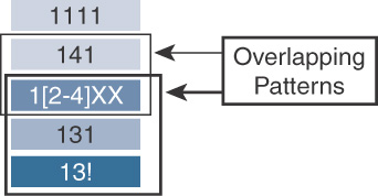
In Figure 7-11, a user dials 13115. CUCM interprets the number digit by digit as the user enters the digits on the keypad of the phone. After all received digits are analyzed, the only match is 13!. Although there is only a single matching pattern, CUCM must wait for additional digits, because the matched pattern is of variable length (the ! wildcard represents one or more digits). The call can be sent to the device that is associated with pattern 13! only after the interdigit timeout expires. In this scenario, you could lower the T302 timer or add a pattern 13!# to reduce or eliminate postdial delays.
If the user dials 131, the user also experiences a postdial delay. After these three digits are analyzed, there are two longer potential matches remaining (1[2–4]XX and 13!). CUCM detects that the end user finished dialing and that the longer matches are not applicable only after the interdigit timeout expires.
If the user dials 1415, the only matching pattern is 1[2–4]XX. This pattern does not include the ! wildcard, and CUCM does not have to wait for additional dialed digits. The call to 1415 can be routed immediately after receiving the fourth digit.
Urgent Priority
This section describes the function of the Urgent Priority parameter. Figure 7-12 shows the Urgent Priority option checked under the Route Pattern Configuration screen.
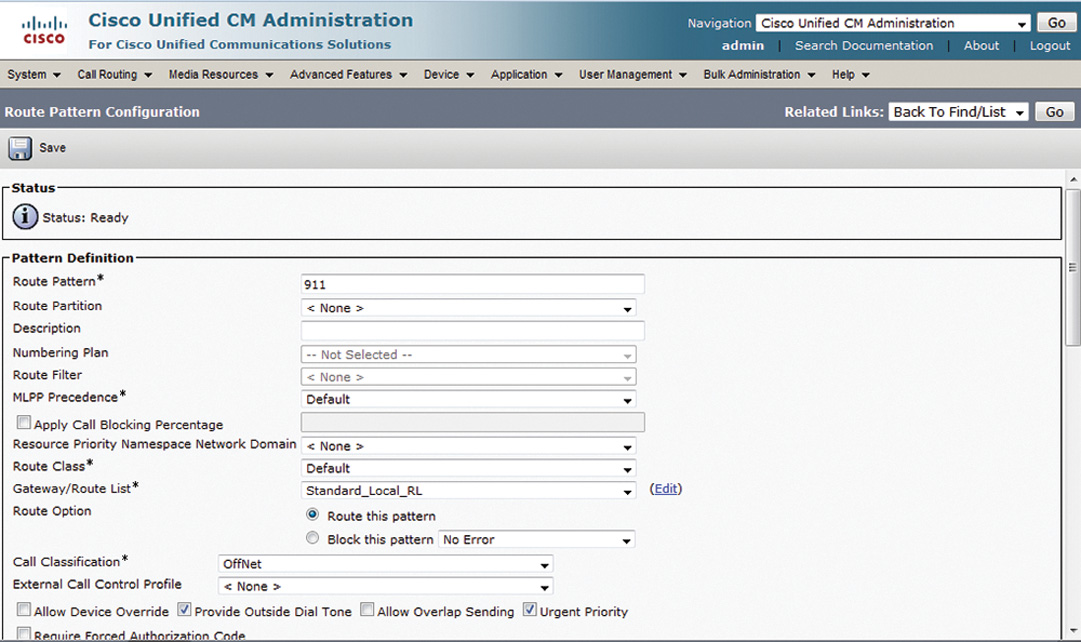
Route patterns, translation patterns, and directory numbers have the Urgent Priority check box. The Urgent Priority check box can be used to force immediate routing of certain calls as soon as a match is detected, without waiting for the interdigit timer to expire when additional potential longer matches exist.
For example, in North America, if the patterns 9.911 and 9.[2–9]XXXXXX are configured and a user dials 9911, CUCM usually must wait for the interdigit timeout before routing the call, because further digits might cause the 9.[2–9]XXXXXX pattern to match. However, when urgent priority is enabled for the 9.911 route pattern, CUCM makes its routing decision as soon as the user has finished dialing 9911, without causing any postdial delay.
When you enable urgent priority, the specified route pattern is excluded from other, longer route pattern matches. If en bloc dialing is used and the provided number is longer than the urgent pattern, the urgent pattern is not considered.
Cisco Unified Communications Call Routing Logic
This section describes the call routing logic in CUCM.
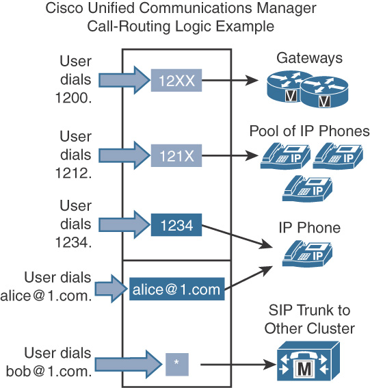
Figure 7-13 illustrates the concept of digit matching for call handling. When a number is dialed, CUCM uses closest-match logic to select which pattern to match from among all the patterns in its call routing table.
In practice, when multiple potentially matching patterns are present, the destination pattern is chosen based on the following criteria:
![]() The pattern matches the dialed string.
The pattern matches the dialed string.
![]() The pattern represents the smallest number of endpoints.
The pattern represents the smallest number of endpoints.
Note
Some entries of the call routing table can include wildcards. For example, an X in a numbered pattern represents one digit. If the exclamation point (!) is used in a numbered pattern, it stands for one or more digits.
Figure 7-13 shows an example in which the call routing table includes the numbered patterns 12XX, 121X, and 1234. The following examples explain the digit analysis and matching in CUCM based on Figure 7-13.
![]() When a user dials the string 1234, CUCM compares the string to the patterns in its call routing table. In this case, there are two potentially matching patterns: 12XX and 1234. Both of these patterns match the dialed string, but 12XX matches a total of 100 numbers (from 1200 to 1299), whereas 1234 does not include any wildcard and therefore is one exact number. Based on closest-match logic, 1234 is selected as the destination of this call.
When a user dials the string 1234, CUCM compares the string to the patterns in its call routing table. In this case, there are two potentially matching patterns: 12XX and 1234. Both of these patterns match the dialed string, but 12XX matches a total of 100 numbers (from 1200 to 1299), whereas 1234 does not include any wildcard and therefore is one exact number. Based on closest-match logic, 1234 is selected as the destination of this call.
![]() When a user dials the string 1210, then the pattern 121X is chosen, because out of the two potential matches, 121X and 12XX, 121X is the better match because it represents 10 numbers while 12XX represents 100 possible numbers.
When a user dials the string 1210, then the pattern 121X is chosen, because out of the two potential matches, 121X and 12XX, 121X is the better match because it represents 10 numbers while 12XX represents 100 possible numbers.
![]() When a user dials the URI [email protected], CUCM chooses the locally configured URI that is an exact match of the dialed URI.
When a user dials the URI [email protected], CUCM chooses the locally configured URI that is an exact match of the dialed URI.
![]() When a user dials the URI [email protected], the only match is the SIP route pattern * (which stands for any URI). If there was a SIP route pattern *.1.com, then a call to [email protected] would find a better match in the *.1.com SIP route pattern, because it is more specific than the * SIP route pattern.
When a user dials the URI [email protected], the only match is the SIP route pattern * (which stands for any URI). If there was a SIP route pattern *.1.com, then a call to [email protected] would find a better match in the *.1.com SIP route pattern, because it is more specific than the * SIP route pattern.
Call Routing Components
As briefly explained in Chapter 6, “Overview of Dial Plan Design and Implementation in Cisco Unified Communications Manager,” CUCM-based call routing has a few important elements. To recap, these elements are:
![]() Route pattern
Route pattern
![]() Route list
Route list
![]() Route group
Route group
![]() Gateways and trunks
Gateways and trunks
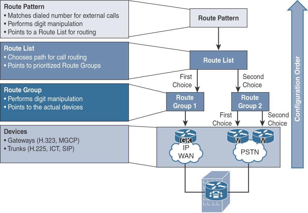
Figure 7-14 gives an insight into the relationship between these call routing elements and the way these elements are configured in the CUCM.
Note
The following sections flow top down (for example, the call flow from route pattern > route list > route group > gateway/trunk) for ease of understanding the call flowing from an endpoint to the PSTN/ITSP. However, in the real world the configuration sequence is bottom up; the gateway or trunk is defined first, then the route group(s) are defined, after which route list(s) are defined, and finally route pattern(s) are defined.
Before getting into the specific details of the call routing elements, the next section explains route plan report that is a comprehensive report of the various call routing and endpoint addressing elements in CUCM.
Route Plan Report
If you wish to get a comprehensive report containing the whole dial plan construct of CUCM, the route plan report is your single source of truth. It contains a listing of all the phone numbers, call park numbers, call pickup numbers, conference numbers (such as Meet-Me numbers), route patterns, and translation patterns in the system. The route plan report allows you to view either a partial or full list. You can accomplish this by selecting a route pattern, partition, route group, route list, call park number, call pickup number, conference number, or gateway. Figure 7-15 shows a route plan report illustrating the DNs, route patterns, translation patterns, and so on. To generate a route plan report, go to Call Routing > Route Plan Report.
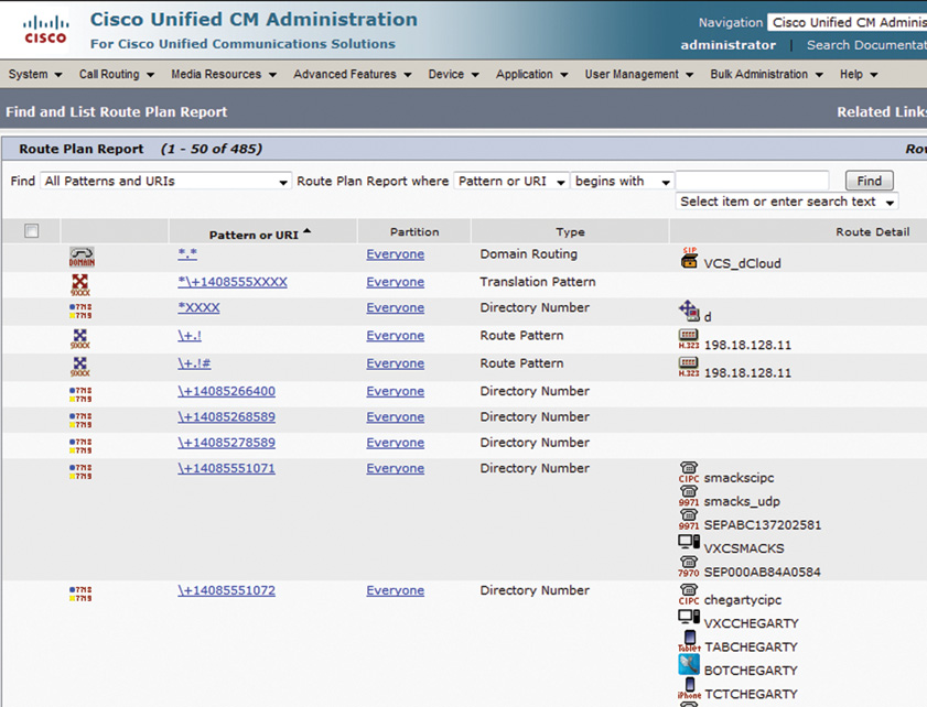
The route plan report can be saved as a comma-separated values (CSV) file that you can import into other applications (such as Microsoft Excel). To save the route plan report as CSV, click on the View in file option on top right corner.
Note
The CSV file contains more detailed information than the web pages, including DNs for phones, route patterns, and translation patterns.
The following sections describe the call routing components of CUCM.
Route Pattern
CUCM does not know about any phone numbers external to CUCM. That’s where the gateway endpoints and trunks allow CUCM to communicate with other systems using traditional TDM interfaces (FXO/FXS/T1-CAS/T1-PRI/E1-CAS/E1-PRI) or an IP-IP gateway such as CUBE; using H.323 or SIP as the communication protocols. A route pattern is a configured numeric pattern range that helps CUCM match a number not in its database and route the call outside of the Cisco Collaboration domain. After the route pattern is matched, the call is routed to the final destination.
Building on Figure 7-15, Figure 7-16 illustrates the call routing via route pattern.
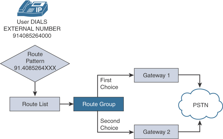
As seen in Figure 7-16, a user dials 914085264000, which is not a number configured in CUCM database and therefore is a number outside of the enterprise network.
CUCM looks in its call routing database and finds the pattern that matches the dialed digits. When the closest match is found (that is, 4085264XXX), CUCM uses the route pattern to route the call out of the network via route pattern > route list > route group > gateway 1 or gateway 2 and to the PSTN.
Table 7-2 lists the various wildcard parameters that are supported in route patterns.
Table 7-2 Route Pattern Wildcards
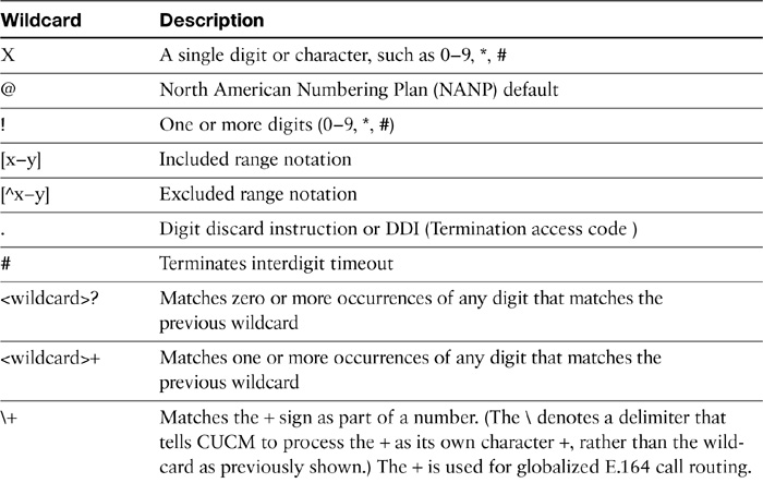
The @ wildcard is a special macro function that expands into a series of patterns representing the entire national numbering plan for a certain country. A route pattern of 9.@ will load a complex 166-route-pattern North American Numbering Plan (NANP) by default. CUCM can be configured to accept other national numbering plans.
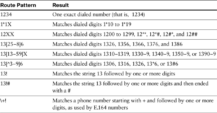
Table 7-3 illustrates the various route patterns that can be matched using the wildcards described earlier.
Table 7-3 Route Pattern Examples
A route pattern can point to a device such as a gateway endpoint or a trunk; however, that will limit the availability of that device only to that specific route pattern. To be able to use device(s) among route patterns, it is important to have them assigned to route groups, which in turn get assigned to route lists, and route lists get assigned to route patterns.
Route patterns can be configured by browsing to Call Routing > Route/Hunt > Route Group and click Add New. Figure 7-17 shows the route pattern configuration to route calls to 4085264XXX numbers.
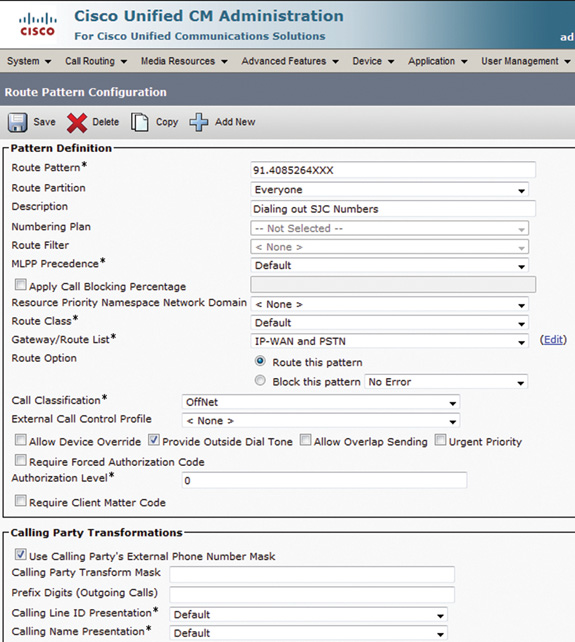
Note that the Route List value IP-WAN and PSTN has been selected, and the Route this pattern radio button is selected. Furthermore, the Call Classification is OffNet and the Provide Outside Dial Tone checkbox is checked.
Digit manipulation can be carried out at Route Pattern or at the route group details level of the route list. These are covered later in the chapter.
Note
The end user can see the manipulated digits if you perform digit manipulation at the route-pattern level. If digit manipulation is done at the route list level, however, the end user will not see that on the phone. Any digit manipulation at the route list level completely overrides the setting at route pattern level.
Route Filters
When creating route patterns, you can use the @ wildcard to represent all the routes defined in the North American Numbering Plan (NANP). This is, however, undesirable in large implementations and where administrators want to exercise fine-grain controls.
Note
NANP includes high-expense patterns such as international dialing access and 900 (premium) numbers.
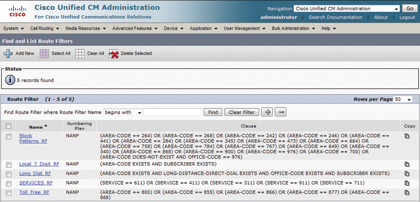
To control what can be dialed from CUCM while using the 9.@, route filters can come in handy. Route filters allow filtering unwanted calls and allow fine-grained control over outbound calls (while leveraging 9.@ route patterns). A number of preconfigured route filters are available in CUCM, as shown in Figure 7-18. These can be accessed by browsing to Call Routing > Route Filter.
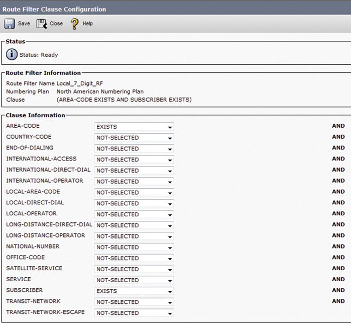
You can design and configure route filters using a number of predefined clauses. Figure 7-19 illustrates the various clauses available.
Note
The clauses shown are for Route Filter Local_7_Digit_RF. These clauses, however, are available for all existing and newly defined route filters.
Once a route filter is defined, it must be applied to an appropriate route pattern using 9.@ for routing calls. Go to Call Routing > Route/Hunt > Route Pattern and select an existing route pattern with 9.@ as the target pattern (or create a new route pattern). Figure 7-20 illustrates the application of a preconfigured or new route filter for the NANP dial plan.
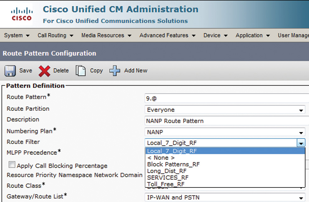
Note that the numbering plan is set to NANP, which will be a greyed-out field if 9.@ is not the target route pattern.
The next section covers route lists.
Route List
A route list is a list of prioritized route groups. Route groups are always processed in a top-down prioritization. Figure 7-21 illustrates the concept of route lists.
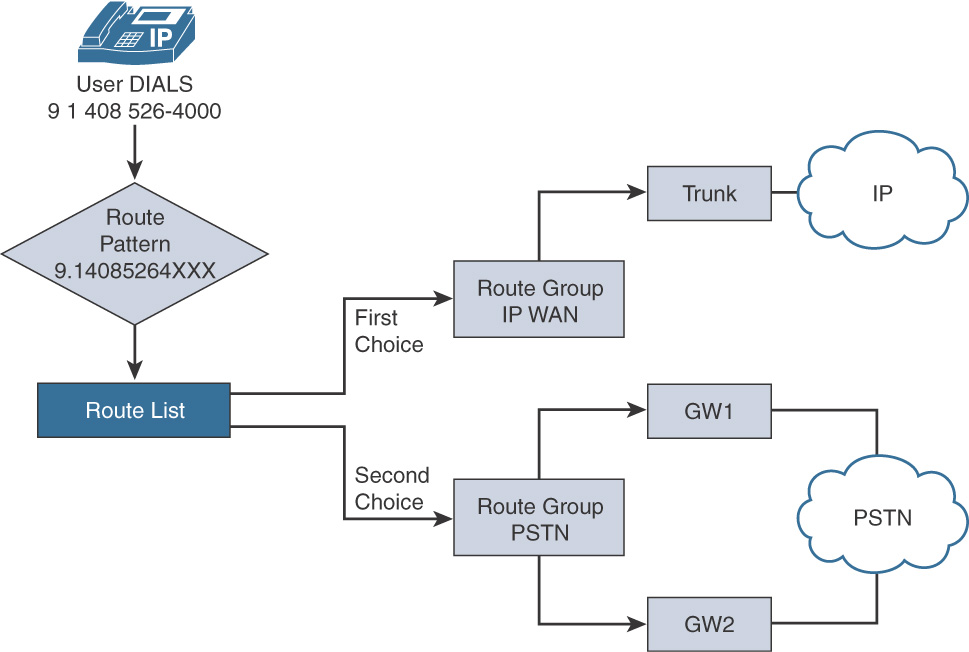
As seen in Figure 7-13, when the user dials 914085264000, the call is routed via the route pattern 914085264XXX to the route list, which in turn routes the call to the prioritized list of route groups, with the first choice being the IP WAN route group and the second choice being PSTN route group. As the name signifies, the IP WAN route group routes calls over the IP trunk to the IP cloud (using ITSP or ICT), whereas the PSTN group routes the call to the traditional PSTN network via one or more gateways.
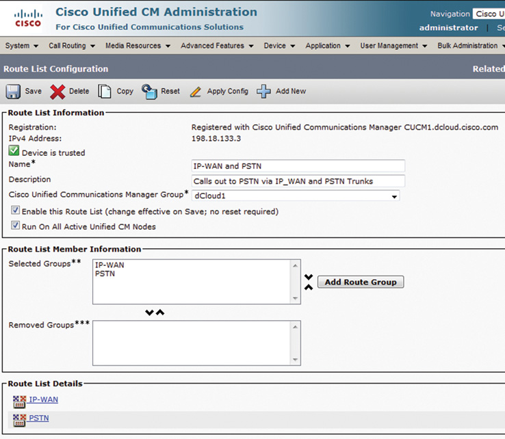
Figure 7-22 shows a route list configuration in which two route groups have been added to the route list example shown in Figure 7-21. To configure a route list, go to Call Routing > Route/Hunt > Route List and click Add New. The IP-WAN route group is listed first and has highest priority. If calls cannot be set up by using any trunk devices in the IP-WAN route group, the next route group in the list (PSTN) is used to route the call.
Route Group
A route group is a list of devices (gateways and trunks). A route group can be configured in two ways:
![]() Circular distribution: Round robin
Circular distribution: Round robin
![]() Top-down distribution: First entry in the list has the highest priority
Top-down distribution: First entry in the list has the highest priority
The circular distribution is used for load-sharing scenarios, when it is desirable to have the two gateways/trunks used equally, for example, without any preference to one or the other. The top-down distribution is used to implement backup paths if the preferred path is unavailable. In other words, the first entry is always used for sending the calls out to the preferred gateway/trunk, and in case the gateway/trunk is unavailable, the secondary option is employed.
Digit manipulation in this model happens on the Route List configuration page, under the Route List Details for the selected route group in the route list. The gateways must have identical digit-manipulation requirements. It is recommended to put devices (gateways or trunks) that have a similar purpose into the same route group.
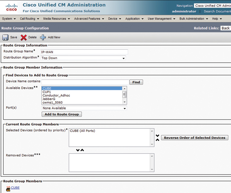
To configure a route group, go to Call Routing > Route/Hunt > Route Group and click Add New. Figure 7-23 shows the route group with IP-WAN trunks configured that is used by the route list defined in previous section.
Digit manipulation can be enabled at the route group level on the route list configuration page, under the route list details for the selected route group in the route list as shown in Figure 7-24.
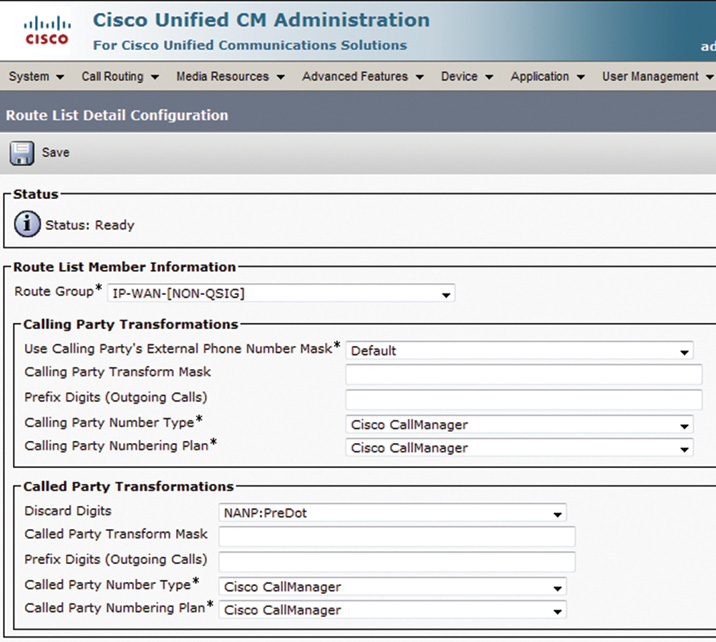
As seen in Figure 7-24, for the called party transformation NANP: PreDot has been selected, and that will discard any predot digits. For example, when 9.14085551001 is dialed, 9 will be discarded.
Local Route Group
Before the introduction of the concept of the local route group, each physical site required a number of dedicated route groups for connecting the internal network with the PSTN world using traditional trunks terminating on voice gateways or CUBE-based SIP trunks to ITSP. The result was a huge number of routing entities leading to complex and sizable dial plans in typical enterprise networks.
Local route groups, however, enable decoupling the selection of a PSTN gateway or trunk for off-net dialing from the route patterns that are used to access the gateway. This greatly reduces the complexity and size of dial plans in CUCM and helps UC administrators manage the network in a better way. The Local Route Group Device Pool parameter was a new call routing element introduced with CUCM 7.0. The standard local route group is a new call routing element that appears in the list of available route groups that can be added to a route list. A route list can include this entry only one time. The local route group is selected by the inclusion in the device’s device pool Local Route Group setting.
Note
The Local Route Group parameter is set to <None> by default.
Route patterns that use the local route group are routed to the gateways that are associated with the local route group configured at the device pool level of the calling device. As a result, each site uses one global dial plan that points to a local route group. The device pool specifies a local gateway router at the site, and the call is routed to a local gateway.
For better understanding, as shown in Figure 7-25 the route pattern 9.1408555XXXX points to a route list that contains only the standard local route group.
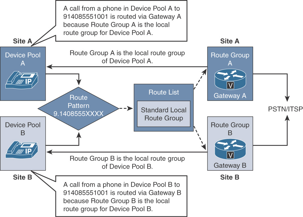
The breakdown of the example is as follows:
![]() Gateway A is associated with Route Group A, which is the local route group of Device Pool A at Site A.
Gateway A is associated with Route Group A, which is the local route group of Device Pool A at Site A.
![]() Gateway B is associated with Route Group B, which acts as the local route group to Device Pool B, at Site B.
Gateway B is associated with Route Group B, which acts as the local route group to Device Pool B, at Site B.
![]() Gateway A is New York gateway, while Gateway B is the San Jose, CA, gateway.
Gateway A is New York gateway, while Gateway B is the San Jose, CA, gateway.
Note
It’s always best to use a local gateway if one is available.
Now, when a phone that is associated with Device Pool A places a call to 914085551001, the standard local route group for this device pool is used to place the call to the PSTN from Gateway A. On the other hand, phones in Device Pool B will have their calls routed to Gateway B because of device pool B’s configured local route group.
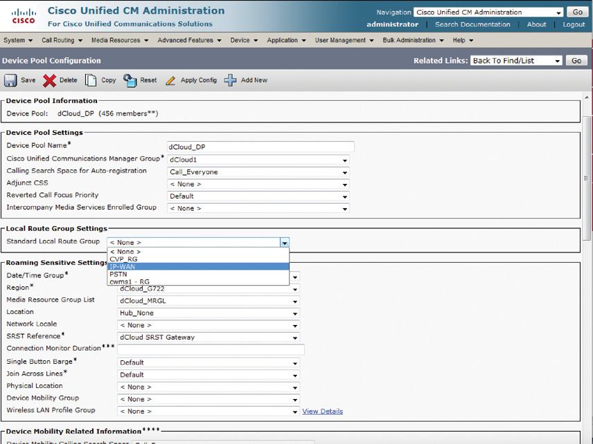
To configure a device pool to leverage Local Route Group, go to System > Device Pool and search for the device pool for which you want to setup a local route group. Figure 7-26 illustrates the selection of a route group from a list of available route groups under the Standard Local Route Group dropdown.
Cisco Unified Communications Manager Based Digit Manipulation
The calls from any phone system need to be sent outside of an enterprise network so the users can communicate with a number of destinations. These destinations in turn might be located within the same site, different sites within the same organization, or other organization (such as partner organizations). The calls may be routed to locations within the same country or to different countries.
Completing various types of calls often requires dialing access codes or prefix numbers, or even the way the calls are presented to the carrier network (PSTN or ITSP). Cisco Unified Communications Manager (CUCM) has the capability to provide digit manipulation, which allows adding or removing digits to comply with a private or public numbering plan.
This section describes digit manipulation tools that allow a CUCM administrator to implement flexibility and transparency in the dial plan of the company by way of implementing external phone number masks, digit prefixing, digit stripping, transformation masks, translation patterns, and significant digits.
At large, three levels of digit-manipulation options are available for outbound calls:
![]() Digit manipulation configured on the route pattern that is used only when a route pattern points directly to a gateway and is not used if the route pattern is routed to the route list
Digit manipulation configured on the route pattern that is used only when a route pattern points directly to a gateway and is not used if the route pattern is routed to the route list
![]() Digit manipulation configured at the route list detail level (application enforced at route group)
Digit manipulation configured at the route list detail level (application enforced at route group)
![]() Digit manipulation configured leveraging a transformation calling search space (CSS) on the gateway/trunk or device pool
Digit manipulation configured leveraging a transformation calling search space (CSS) on the gateway/trunk or device pool
Note
The details about transformation pattern and CSS are covered later in the chapter.
The next section gives an overview of digit manipulation in CUCM.
Digit Manipulation Overview
Digit manipulation in CUCM is used for multiple purposes:
![]() Digit manipulation is often used to change calling party numbers for caller ID purposes on outgoing PSTN calls
Digit manipulation is often used to change calling party numbers for caller ID purposes on outgoing PSTN calls
![]() Digit manipulation is also used to strip PSTN access codes before CUCM routes the calls to the gateway (PSTN).
Digit manipulation is also used to strip PSTN access codes before CUCM routes the calls to the gateway (PSTN).
![]() Digit manipulation is required for abbreviated dialing and to properly route inbound calls from the PSTN where an abbreviated internal dial plan exists.
Digit manipulation is required for abbreviated dialing and to properly route inbound calls from the PSTN where an abbreviated internal dial plan exists.
![]() Digit manipulation is required to strip off PSTN access codes from the called party number before routing the call to the PSTN.
Digit manipulation is required to strip off PSTN access codes from the called party number before routing the call to the PSTN.
![]() Digit manipulation is used at times to change the calling party number from the abbreviated internal extension number to a full E.164 PSTN number to allow an easier redial (redialing by the called party) and for proper representation on the PSTN network.
Digit manipulation is used at times to change the calling party number from the abbreviated internal extension number to a full E.164 PSTN number to allow an easier redial (redialing by the called party) and for proper representation on the PSTN network.
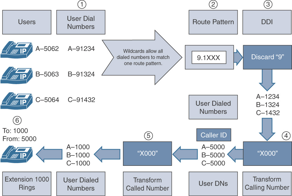
Figure 7-27 gives an insight into the digit manipulation for call flows within an organization.
Note
This is a typical example of how calls can be forced on net. For example, if the number belongs to an organization, the call may not be sent out to the PSTN but forced to be on net by manipulating digits, therefore saving toll charges. The user is never aware of the change, and for the user the whole experience remains transparent. Moreover, this example illustrates the use of various digit manipulation mechanisms at once. These are discussed in detail in the following sections.
In Figure 7-27, the following sequence of events occurs:
Step 1. Users at extension (DN) 506[2-4] dial 91[2-4]XX. CUCM intercepts the call and realizes that it has a route pattern to match the dialed number, that is, 91XXX (closest match).
Step 2. The call hits route pattern 9.1XXX (note the period (.) between 9 and 1)
Step 3. The discard digit instruction (DDI) is set to discard 9 and keep 1XXX.
Step 4. Within the route pattern, the calling number is transformed to X000, that is, taking the three most significant digits “as is” from the calling party and mapping the first digit, that is the least significant digit. Essentially any and all calling party numbers, for example 5062, 5063, and 5064, are changed to 5000.
Step 5. Using the called party transformation mask, the least significant digit is taken “as is,” while the three most significant digits are replaced by 0. Essentially, all calls to 1234, 1324, and 1432 are now changed to 1000.
Step 6. DN 1000 is a local number configured in the CUCM database, and the extension rings, with the calling party DN as 5000.
The following sections describe the various digit manipulation methods.
External Phone Number Mask
The external phone number mask is leveraged in call routing to manipulate the internal directory number to digits that can be routed over the PSTN. The external phone number mask is configured on the DN configuration page in CUCM.
Additionally, the external phone number mask is available in the following entities:
![]() Route pattern
Route pattern
![]() Route list (via route group configuration as described earlier)
Route list (via route group configuration as described earlier)
![]() Translation pattern
Translation pattern
![]() Transformation pattern (Calling Party Transformation Pattern)
Transformation pattern (Calling Party Transformation Pattern)
![]() Hunt pilot
Hunt pilot
The external phone number mask is used for the following functions:
![]() For automated alternate routing (AAR), the external phone number mask is used to change the internal dial plan into a PSTN-routable dial plan when rerouting intersite calls from the WAN to the PSTN (in case of WAN congestion).
For automated alternate routing (AAR), the external phone number mask is used to change the internal dial plan into a PSTN-routable dial plan when rerouting intersite calls from the WAN to the PSTN (in case of WAN congestion).
Note
The topic of AAR is covered in Implementing Cisco IP Telephony and Video, Part 2.
![]() To change the display of the main phone number at the top of the LCD screen. A DN of 1001 with an external phone number mask of 408555XXXX would result in a displayed phone number of 4085551001.
To change the display of the main phone number at the top of the LCD screen. A DN of 1001 with an external phone number mask of 408555XXXX would result in a displayed phone number of 4085551001.
![]() To change the display of the caller ID for all calls in which the call classification is OffNet. The calling party number (caller ID) is changed to the full ten-digit DID phone number of the calling party.
To change the display of the caller ID for all calls in which the call classification is OffNet. The calling party number (caller ID) is changed to the full ten-digit DID phone number of the calling party.
Figure 7-28 depicts the External Phone Number Mask of +1408555XXXX for DN 4085551001. To configure an endpoint DN, go to Device > Phone and search for the endpoint for which you want to define the External Phone Number Mask.
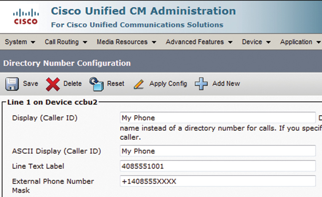
Figure 7-29 illustrates the use of External Phone Number Mask in Route Pattern.
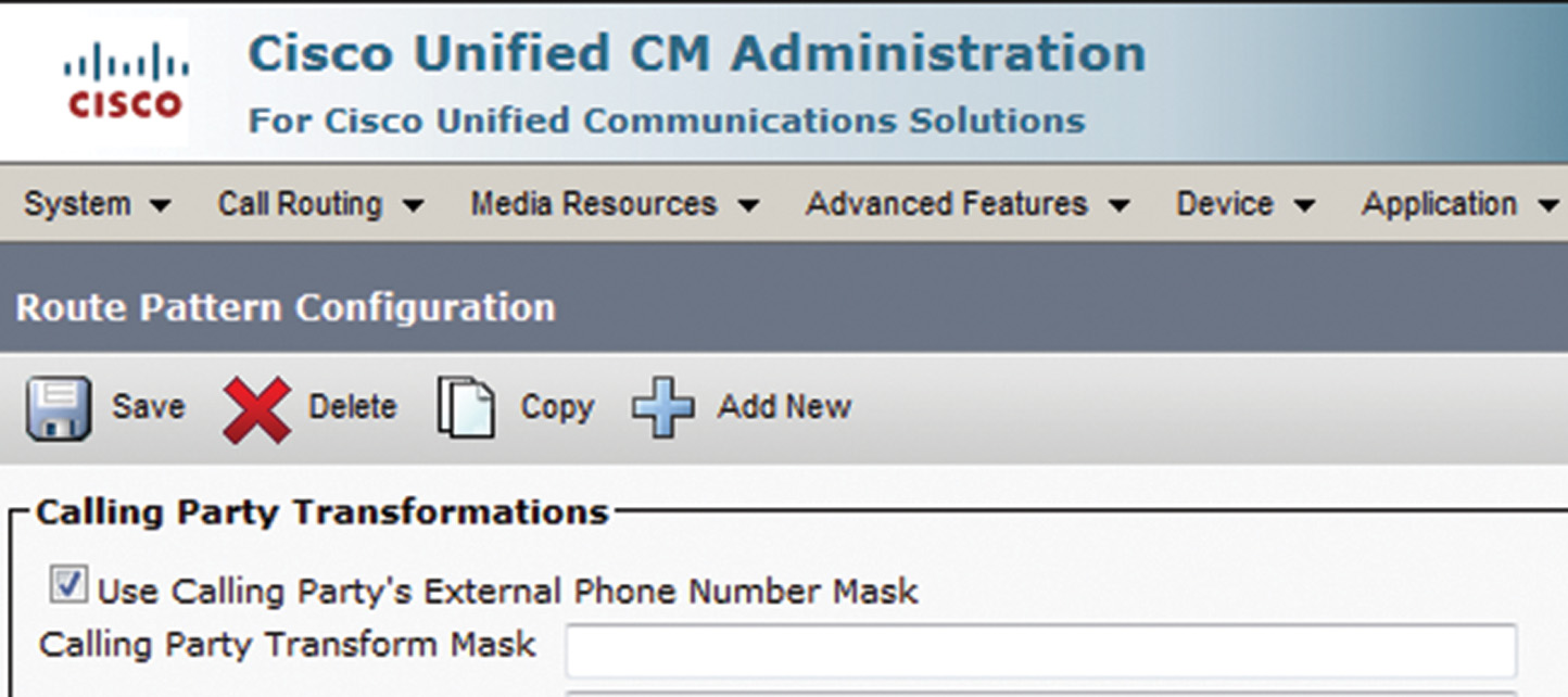
Note
A similar setup is applicable for Translation Patterns, Calling Party Transformation Pattern, and Hunt Pilot configuration where the check box must be checked for the call routing element to leverage the external phone number mask of the originating endpoint.
Significant Digits
For calls coming into a CUCM cluster from PSTN, the E.164 number may not make sense unless it is pruned to match the CUCM internal dial plan (unless the whole dial plan is based on E.164 notation). This is where the Significant Digits feature comes into play and instructs CUCM to analyze the configured number of digits (from right to left) of the called number for incoming calls received by a gateway or a trunk.
Setting the significant digits to four on a PSTN gateway instructs CUCM to ignore all but the last four digits of the called party number for routing incoming gateway or trunk calls. For example if an incoming call is destined for extension 1001 and the incoming number is an E.164 number such as 4085551001, setting the significant digits to four will strip all but last four digits (starting from right). Therefore, the resulting number will be 1001, which matches the inside extension as shown in Figure 7-30.
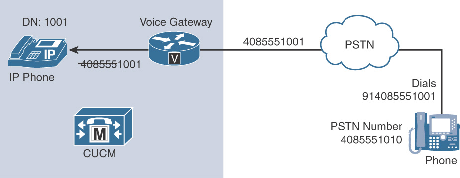
The Significant Digits feature is the easiest approach to convert incoming PSTN called numbers to an internal extension. However, the setting affects all calls received from the gateway. Moreover, the Significant Digits setting also cannot accommodate variable-length extension numbers on the internal network.
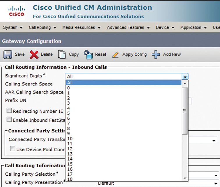
To set up the significant digits, go to Device > Gateway (or Trunk) and select the gateway (or trunk) for which this setting is to be configured. Under the Incoming Calls section, set the Significant Digits to a desired number for your internal dial plan, as shown in Figure 7-31.
CUCM Digit Prefix and Stripping
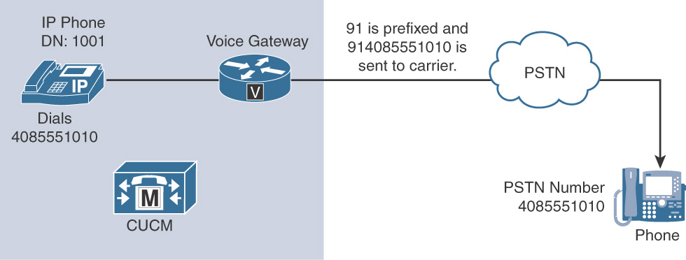
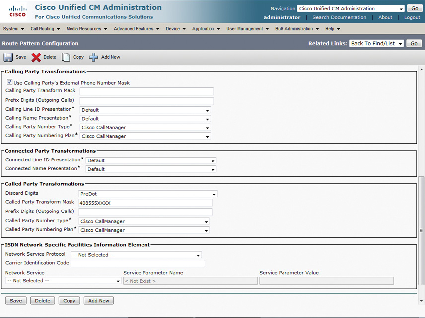
More often than not, it’s required that certain digits be prefixed to outbound calls or stripped from outbound calls for appropriate number presentation to the carrier. The Digit Prefix feature allows prefixing digits to a dialed number. Any digits that can be entered from a standard phone (0 through 9, *, and #) can be prepended to the calling or called party numbers. For example, while dialing a ten-digit number such as 4085551010, 91 may be required by the carrier to route the calls to long-distance numbers. This can be done by prefixing 91 so that the complete outbound number is in E.164 format (for example, 914085551010). Digit prefixing is available for either the calling or called party number and can be configured at the route pattern, route list, or translation pattern levels. Figure 7-32 illustrates the digit prefix instructions at the route pattern level. Similar configuration exists at the route list or translation pattern levels.
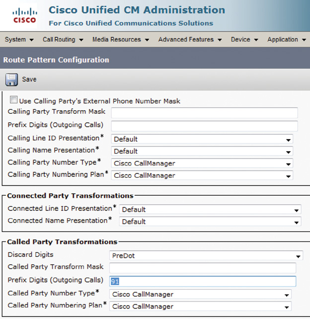
As depicted in Figure 7-33, the user at extension 1001 dials 4085551010, and because this number is not part of CUCM database, it needs to be routed to the PSTN domain. At the route pattern level, the number is matched and is prefixed by 91 before the dialed number is sent to the carrier network.
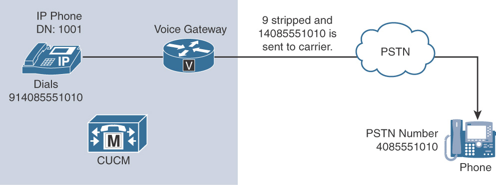
Digit prefixing is the opposite of digit stripping or discard digits instruction (DDI). DDI removes parts of the dialed digit string before passing the number on to the next routing component or out to the PSTN. DDI removes a certain portion of the dialed string, such as the called party. As illustrated in Figure 7-34, DDI is set to discard 9 before the dialed number is sent to the carrier.
Digit stripping is configured in the Called Party Transformations section by selecting a Discard Digits setting from the drop-down menu, as shown in Figure 7-35.
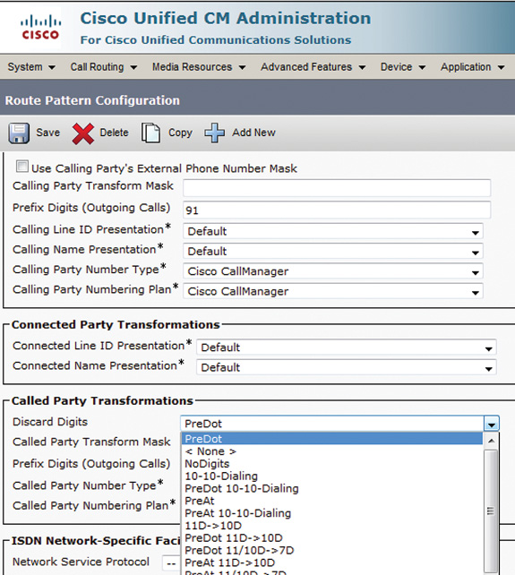
Discard digit instructions can be configured at the route pattern and at the route group details level of the route list.
Note
The PreAt, 11D/10D@7D, 11D@10D, IntlTollBypass, and 10-10-Dialing complex DDIs are not available unless the @ symbol is in the route pattern.
Before proceeding to digit manipulation methods, such as translation patterns and transformation patterns, let’s try to understand the transformation masks. These are available at various levels within the call routing hierarchy—both for internal and external calls—and are key to transform calling party identity and/or called party identity.
Transformation Masks
More often than not, dialing transformations are required to modify either the calling party (initiator of the call) or the called party (destination of the call) number/digits. This is where transformation masks come in handy and allow the UC administrator to modify the calling number or automatic number identification (ANI) as well as adjust the called number or Dialed Number Identification System (DNIS).
As described earlier, digit translation in CUCM is possible through the transformation mask feature that can be found at various levels in CUCM, such as route pattern, route list details (route group), and translation pattern. The calling and called party transformation masks for calls outbound from an enterprise network can be assigned to route groups in the route list details or at route pattern level; that is applicable only when a route pattern is pointed directly to a gateway.
So, how do transformation masks work? Essentially, CUCM overlays the calling or called party number with the transformation mask so that the last character of the mask aligns with the last digit of the calling or called party number.
Note
Transformation masks operate much like significant digits in that the processing is always from right to left.
Now, there can be two situations:
1. A number is presented (calling or called party) and the transformation mask has X (acts as binary OR), so that the part of number matching the transformation mask passes as is.
2. The transformation mask has absolute numbers, in which case the number being transformed is replaced by the pattern matching the transformation mask.
Figure 7-36 gives an overview of transformation masks and the transformation operation.
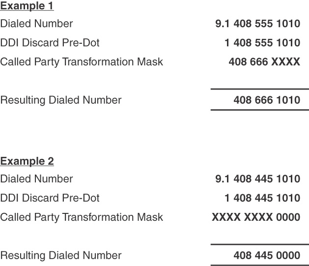
As shown in Example 1 of Figure 7-36, the right-most four digits are passed “as is,” whereas the rest of the number is changed from 408 555 to 408 666 (that is, number replacement). Subsequently in Example 2, while the first six digits (408 445) are kept “as is,” the latter part or the most significant digits of the number are changed from 1010 to 0000.
If the number is longer than the mask, the mask adds extra digits to the original calling or called party pattern.
To configure transformation mask browse to the route pattern, route list detail (route group), or translation pattern via Call Routing menu and to configure the Calling Party Transformation Mask (under Calling Party Transformation) or Called Party Transformation Mask (under Called Party Transformation), enter data as shown in Figure 7-37.
The next section describes translation patterns.
Translation Patterns
Translation patterns can be leveraged to manipulate digits before forwarding a call. A translation pattern is much like route pattern but with a difference; while a route pattern has access to external call routing elements, a translation pattern doesn’t. In simpler terms, a route pattern is used to route calls outside of a CUCM cluster, whereas a translation pattern is used for routing calls within a CUCM cluster; thus there is post-digit manipulation. Also, both translation patterns and route patterns can be used to block patterns, but the default action is to attempt call routing.
Translation patterns use route pattern style matching and transformation mask-based digit manipulation. The pattern resulting after the translation pattern is applied is then rerouted by the system, thereby causing a second round of digit analysis. Eventually, the call is either routed to a device or blocked by CUCM.
Note
CUCM allows processing digits through translation patterns for only ten iterations to prevent call routing loops.
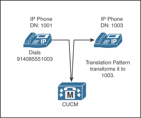
Figure 7-38 depicts a translation pattern to match 914085551XXX and transform the number into four-digit extension to keep the call on net. This is particularly useful when a range of numbers are owned by an organization and toll charges are to be avoided by keeping the calls on net (irrespective of user dialing behavior of four-digit or full E.164 number dialing).
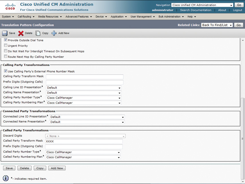
To configure a translation pattern, navigate to CUCM Administration, then go to Call Routing > Translation Pattern.
Figure 7-39 gives an insight into the call flow described earlier using the translation pattern.
In case a translation pattern contains an @ sign, similar to a route pattern, a numbering plan and route filter can be selected to match certain number patterns of the selected numbering plan. Translation patterns are processed as urgent priority by default, and this can be disabled by unchecking the box.
Translation patterns can be leveraged in a host of situations such as:
![]() Extension mapping from public to private (internal) network
Extension mapping from public to private (internal) network
![]() Abbreviated dialing to PSTN locations
Abbreviated dialing to PSTN locations
![]() Hotlines with a need for Private Line Automatic Ringdown (PLAR) functionality
Hotlines with a need for Private Line Automatic Ringdown (PLAR) functionality
The next section discusses the transformation patterns.
Transformation Patterns
The support for number normalization and number globalization support for E.164-based call routing was introduced in CUCM version 7.0. Calling and called party transformation patterns extend CUCM’s ability to manipulate digits much more, especially when the organizations deploy a globalized routing plan. Calling and called party transformation patterns are applicable only to calls from CUCM to gateways, trunks, and endpoints (phones).
During digit analysis, CUCM treats transformation patterns similar to any other pattern in the call routing database (for example, a translation pattern or route pattern). Moreover, like any other calling search space (CSS), the calling and called transformation CSS can be used to restrict the patterns that are matched for the purpose of digit transformation. Calling and called party transformation CSSs can be applied in the phone, gateway, and device pool configuration locations of CUCM administration. Figure 7-40 shows the application of transformation CSS on an IP Phone.
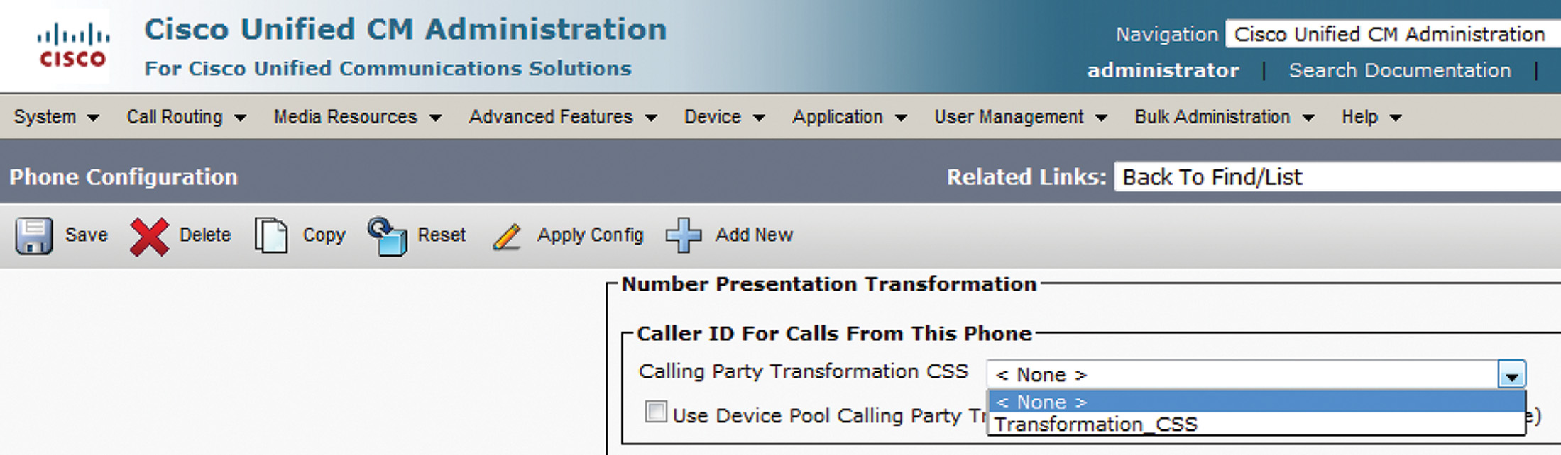
Figure 7-41 shows the option to select transformation CSS for calling or called party at the device pool level.
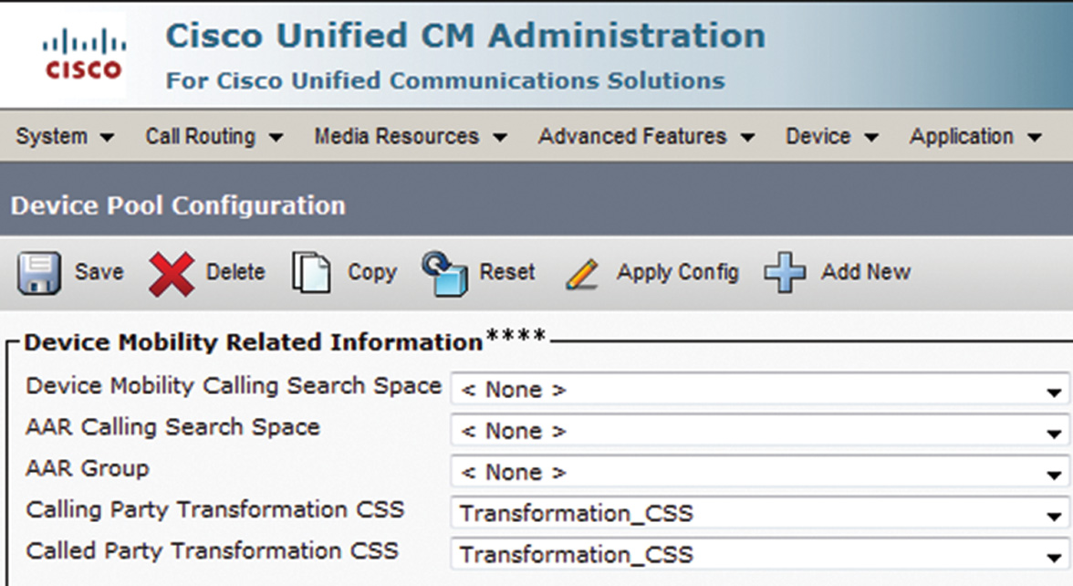
It is important to understand that instead of configuring an individual calling and called party transformation CSS at the device level, you can configure the devices to use calling and called party transformation CSSs configured at the device pool level. However, no transformation is performed if the device and associated device pool are not configured with a transformation CSS.
Note
Transformations patterns apply only to the outgoing call leg.
Calling and called party transformation patterns have the following key characteristics:
![]() Transformations are implemented in the global CUCM configuration.
Transformations are implemented in the global CUCM configuration.
![]() Calling and called party transformation patterns can be put into partitions, and access can be controlled tightly.
Calling and called party transformation patterns can be put into partitions, and access can be controlled tightly.
![]() Gateways and trunks can be configured with calling and called party transformation CSSs. Calling party transformations are supported on the Cisco IP phone, but called party transformations are not.
Gateways and trunks can be configured with calling and called party transformation CSSs. Calling party transformations are supported on the Cisco IP phone, but called party transformations are not.
![]() The transformation CSS determines which transformation patterns are visible to the device.
The transformation CSS determines which transformation patterns are visible to the device.
It’s important to realize that different levels of digit manipulation are not utilized all at once. For instance, only one level of digit manipulation will be applied on a case-by-case basis. Examples include:
![]() Any digit manipulation matches through a gateway or trunk transformation CSS results in all other digit manipulations being ignored.
Any digit manipulation matches through a gateway or trunk transformation CSS results in all other digit manipulations being ignored.
![]() Digit manipulation settings on the route pattern take effect only when the route list details do not have any defined digit manipulations (as described earlier).
Digit manipulation settings on the route pattern take effect only when the route list details do not have any defined digit manipulations (as described earlier).
![]() A transformation CSS applied at the gateway/trunk or device pool will lead to the digit manipulations applied at the route pattern level to be skipped.
A transformation CSS applied at the gateway/trunk or device pool will lead to the digit manipulations applied at the route pattern level to be skipped.
![]() In case a transformation calling search space (CSS) is configured on the device selected to route the call (or on that device’s device pool), then transformations configured in the route pattern or route list are considered only if no match is found using the respective transformation CSS.
In case a transformation calling search space (CSS) is configured on the device selected to route the call (or on that device’s device pool), then transformations configured in the route pattern or route list are considered only if no match is found using the respective transformation CSS.
Note
The input to the transformation CSS always is the untransformed number before applying route pattern or route list transformations.
The following sections detail some examples of transformation patterns.
Note
DDI, digit prefixing, and other digit manipulation mechanisms are inherent to these use cases; however, they are not explicitly called out for ease of understanding.
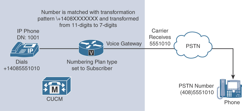
Use Case 1
The user dials +14085551010 in partition A, and the number is modified from an 11-digit called party number in globalized number format (globalized dial plan) into a seven-digit called party number along with setting the numbering plan type to subscriber. Figure 7-42 gives an insight to the call flow.
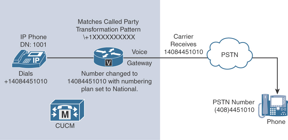
Use Case 2
A user dials a +1XXXXXXXXXX globalized number. This pattern matches on all 11-digit patterns, beginning with the E.164 + character used to route international calls followed by a 1 and any ten digits. However, the pattern represents US area codes within a globalized route plan. As shown in Figure 7-43, the dialed number +14084451010 is matched and transformed on the gateway to 14084451010, with type national.
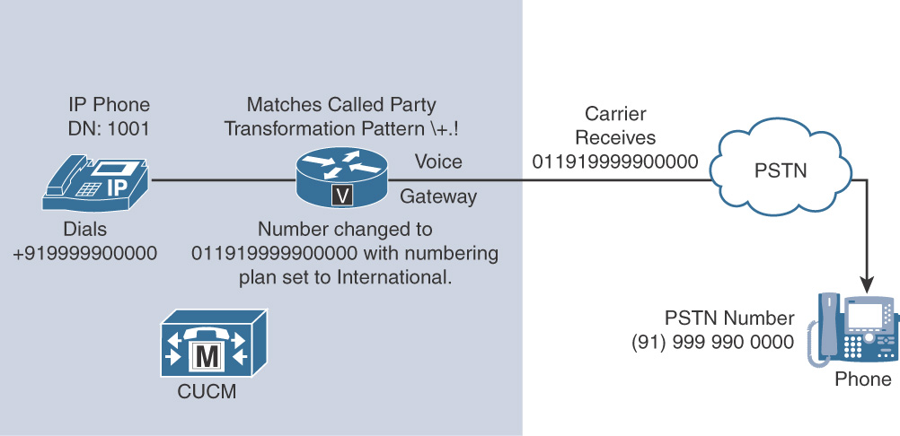
Use Case 3
A user dials +919999900000 which is a globalized number that is in turn an international number. The dialed number, +91999990000 (for India), is matched and transformed on the gateway with a prefix of 011 to indicate that this is an international call. Figure 7-44 depicts the call flow.
Note
Refer to Implementing Cisco IP Telephony and Video Part 2 for a detailed discussion on globalized dial plans.
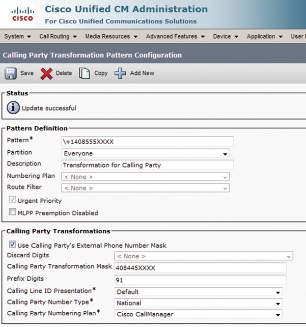
To configure a calling number transformation pattern, go to Call Routing > Transformation > Transformation Pattern > Calling Party Transformation Pattern. Figure 7-45 shows the configuration of a calling party transformation pattern. In this case, when a user set to use the external phone number mask (defined by the checkbox) dials and external number; the caller ID is transformed into 408445XXXX (keeping the last four digits “as is”). Finally, the caller ID is prefixed by 91 and sent with Calling Party Number Type as National.
To configure a called party transformation pattern, go to Call Routing > Transformation > Transformation Pattern > Called Party Transformation Pattern. Figure 7-46 illustrates the configuration of a called party transformation pattern.
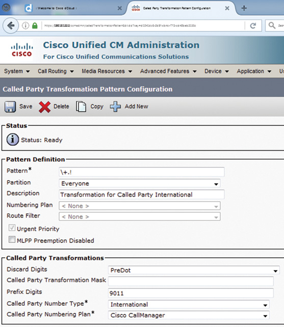
In this case, when a user calls an international number, the transformation pattern +.! is matched, and the called party number (such as +.919999908169) is subjected to the pre-dot digit discard mechanism, followed by the prefix 9011, and the Called Party Number Type is set as International.
To invoke a transformation pattern, the associated partition must be part of the transformation CSS at the device (gateway, trunk, or IP Phone) or device pool level.
Incoming transformation settings have the following characteristics:
![]() Incoming calling and called party settings apply to calls received from gateways and trunks. They are not applicable to calls received from phones. In case of IP phones, the external phone number mask of directory numbers is used to globalize the calling party number from Cisco IP phones.
Incoming calling and called party settings apply to calls received from gateways and trunks. They are not applicable to calls received from phones. In case of IP phones, the external phone number mask of directory numbers is used to globalize the calling party number from Cisco IP phones.
![]() They allow the configuration of digit stripping, digit prefixes, and transformations to be applied to calling and called party numbers for calls inbound from trunks (another CUCM cluster or ITSP) and the PSTN to the CUCM cluster.
They allow the configuration of digit stripping, digit prefixes, and transformations to be applied to calling and called party numbers for calls inbound from trunks (another CUCM cluster or ITSP) and the PSTN to the CUCM cluster.
![]() Different settings can be configured per number plan type (unknown, subscriber, national, and international) if the information is available in the call signaling.
Different settings can be configured per number plan type (unknown, subscriber, national, and international) if the information is available in the call signaling.
![]() Incoming calling and called party settings can be configured at the device, device pool, and/or global service parameter configuration levels in CUCM Administration.
Incoming calling and called party settings can be configured at the device, device pool, and/or global service parameter configuration levels in CUCM Administration.
Note
H.225 trunks and H.323 gateways support incoming calling and called party settings based on numbering plan type, but Media Gateway Control Protocol (MGCP) gateways support only incoming calling party settings based on numbering plan type. Session Initiation Protocol (SIP) does not support numbering plan types.
Chapter Summary
The following list summarizes the key points that were discussed in this chapter:
![]() In CUCM, endpoints can be identified by directory numbers and directory URIs.
In CUCM, endpoints can be identified by directory numbers and directory URIs.
![]() Call routing is the procedure in which CUCM processes incoming call requests by looking up the dialed number in its call routing table.
Call routing is the procedure in which CUCM processes incoming call requests by looking up the dialed number in its call routing table.
![]() Route patterns, route lists, route groups, and gateways/trunks form the essential elements for routing external calls from CUCM.
Route patterns, route lists, route groups, and gateways/trunks form the essential elements for routing external calls from CUCM.
![]() The best matching entry is used to route a call. The best match is the pattern that represents the fewest numbers.
The best matching entry is used to route a call. The best match is the pattern that represents the fewest numbers.
![]() When not all digits of a called number are received at once, the dialed digits are analyzed as they are received.
When not all digits of a called number are received at once, the dialed digits are analyzed as they are received.
![]() In digit-by-digit analysis, overlapping patterns can cause post-dial delays. Configure shorter overlapping patterns as urgent so that they are processed immediately, even if longer overlapping patterns exist.
In digit-by-digit analysis, overlapping patterns can cause post-dial delays. Configure shorter overlapping patterns as urgent so that they are processed immediately, even if longer overlapping patterns exist.
![]() Digit manipulation is useful in multiple ways—from keeping a call on net to presenting the right caller ID to ensuring that an incoming call hits the right destination.
Digit manipulation is useful in multiple ways—from keeping a call on net to presenting the right caller ID to ensuring that an incoming call hits the right destination.
![]() Multiple tools are available in CUCM for enabling and using digit manipulation for calling and called numbers, such as external phone number mask, discard digit instructions, translation patterns, transformation patterns, and so on.
Multiple tools are available in CUCM for enabling and using digit manipulation for calling and called numbers, such as external phone number mask, discard digit instructions, translation patterns, transformation patterns, and so on.
![]() DDI and digit prefixes allow digit manipulation by discarding and adding digits to a number respectively.
DDI and digit prefixes allow digit manipulation by discarding and adding digits to a number respectively.
![]() Significant digits allow defining the number of digits that should be considered when a number enters CUCM from the outside world (PSTN). This allows direct matching of the internal extension.
Significant digits allow defining the number of digits that should be considered when a number enters CUCM from the outside world (PSTN). This allows direct matching of the internal extension.
![]() Translation patterns are much like route patterns, expect that they allow call routing within a CUCM cluster. They’re used for digit manipulation and enable passing a call up to 10 times within a translation pattern construct before the call can be sent to another call routing entity.
Translation patterns are much like route patterns, expect that they allow call routing within a CUCM cluster. They’re used for digit manipulation and enable passing a call up to 10 times within a translation pattern construct before the call can be sent to another call routing entity.
![]() Transformation patterns allow changing the calling party (ANI) or the called party (DNIS)
Transformation patterns allow changing the calling party (ANI) or the called party (DNIS)
References
For additional information, refer to the following:
Cisco Systems, Inc. Cisco Collaboration System 10.x SRND, June 2014. http://www.cisco.com/c/en/us/td/docs/voice_ip_comm/cucm/srnd/collab10/collab10.html.
Review Questions
Use the questions here to review what you learned in this chapter. The correct answers are found in Appendix A, “Answers to the Review Questions.”
1. What dial plan element is used to match the dialed digits for call routing to another cluster or the PSTN?
a. Route pattern
b. Route list
c. Route group
d. Gateway
e. Trunk
2. What dial plan element is responsible for changing digits and sending the call for another dial plan lookup?
a. Directory numbers
b. Translation pattern
c. Route pattern
d. Hunt pilot
e. Meet-me numbers
3. Which of the following wildcards represents a variable length number?
a. @
b. !
c. X
d. T
e. #
4. Which of the following wildcards represent a single digit?
a. @
b. !
c. X
d. T
e. #
f. ( )
5. Which of the following wildcards represents the termination of the interdigit timeout?
a. @
b. !
c. X
d. T
e. #
6. Which of the following two patterns does the route pattern 13[1349]X match?
a. 13130
b. 13199
c. 1310
d. 1349
7. What will happen when a user dials 90114912345 as en bloc dialing and CUCM matches the call to the route pattern 9.011!?
a. The call will fail
b. The call will route immediately after the dial button is pressed
c. CUCM will wait for the # key press
d. CUCM will wait for the T302 timer to expire
8. How should you configure the T302 timer?
a. Disable the timer by setting the value to 0
b. Leave the timer at its default value for best results
c. Set the timer to a value of 1 to enable the timer
d. Lower the value from the default to keep post-dial delay at an acceptable level
9. What happens when the urgent priority box is checked on a pattern?
a. CUCM process the call right after the T302 timer expires
b. CUCM allows all callers to dial this number
c. CUCM does not wait for the T302 timer to expire but routes the call as soon as a pattern of the correct length is found
d. CUCM sends the call as a 911 urgent call
10. Where is a URI configured?
a. In the OTLD parameter
b. In the directory number page
c. Assigned via a translation pattern
d. In the Application User details page
11. Which two patterns will match +1.!?
a. +1408551010
b. +493534447890
c. +14084451001
d. A URI matching the DN of the dialed number
12. True or false? The ANI is the number called by the user.
a. True
b. False
13. A route filter can be provisioned to control the calls when using the @ sign in a pattern expression. At which place can a route filter be used?
a. Route group
b. Route list
c. Route pattern
d. Phone DN
14. What will be the result of matching a called number 4085556000 with the transformation mask 55588XXXXX?
a. The resulting number will be 4085556000
b. The resulting number will be 5558856000
c. The resulting number will be 5558886000
d. The resulting number will be 5555556000
15. A Cisco SCCP protocol–controlled phone supports which two dialing mechanisms?
a. En bloc
b. KPML
c. Digit-by-digit
d. Overlap send and receive