Chapter 11. Cisco Video Conferencing
Cisco offers a range of video conferencing solutions for small, medium, and large enterprises. These solutions offer state-of-the-art video conferencing that enables the mobile workforce, customers, and remote offices to be connected. This in turn improves real-time decision making and provides an in-person experience that is immersive and pervasive.
The Telepresence server and MSE 8000 Series provide high-density, high-performance conferencing services. This chapter presents an overview of these platforms and describes their architecture, capabilities, and available features.
Chapter Objectives
Upon completing this chapter, you will be able to meet the following objectives:
![]() Describe the features and capabilities of the Cisco TelePresence MSE 8000 Series.
Describe the features and capabilities of the Cisco TelePresence MSE 8000 Series.
![]() Describe the Cisco TelePresence MSE 8000 feature blades.
Describe the Cisco TelePresence MSE 8000 feature blades.
![]() Describe the capabilities of the feature blades.
Describe the capabilities of the feature blades.
![]() Explain how to enable access the Cisco TelePresence MSE 8000 feature blades.
Explain how to enable access the Cisco TelePresence MSE 8000 feature blades.
![]() Describe how to integrate Cisco TelePresence Server with Cisco Unified Communications Manager (CUCM).
Describe how to integrate Cisco TelePresence Server with Cisco Unified Communications Manager (CUCM).
![]() Describe the integration options of Cisco TelePresence conferencing resources with Cisco Unified Communications Manager (CUCM) when using Cisco TelePresence Conductor.
Describe the integration options of Cisco TelePresence conferencing resources with Cisco Unified Communications Manager (CUCM) when using Cisco TelePresence Conductor.
Cisco TelePresence MSE 8000 Overview
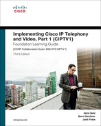
The Cisco TelePresence MSE 8000 series is a highly scalable and flexible chassis-based platform for high-definition video conferencing and voice communication. This platform is a powerful, fault-tolerant solution designed for the mission-critical communication needs of large enterprises. The Cisco TelePresence MSE 8000 series chassis can support up to ten blades and two fan trays. The first slot is reserved for the Cisco Supervisor MSE 8050 blade, while the other nine slots can be used for Cisco TelePresence MCU media blades or other Cisco TelePresence MSE 8000 series service blades. Figure 11-1 gives an overview of the Cisco TelePresence MSE 8000 series chassis.
The Cisco TelePresence MSE 8000 is ideal for the large-scale communication needs of sizeable enterprises and service providers that require a scalable high-availability and high-performance conferencing solution. Cisco TelePresence MSE 8000 offers the following functionalities:
![]() Multipoint Control Unit (MCU)
Multipoint Control Unit (MCU)
![]() Cisco TelePresence Server
Cisco TelePresence Server
![]() ISDN and serial gateways
ISDN and serial gateways
Cisco Supervisor MSE 8050 blade occupies the first slot on the Cisco MSE 8000 series chassis. Cisco TelePresence Server is available as an MSE 8710 blade for the Cisco TelePresence MSE 8000 series chassis. This option is suitable for organizations that already have a Cisco TelePresence MSE 8000 or need greater video conferencing capacity. Cisco TelePresence MCU MSE 8510 Media 2 Blade offers the MCU functionality and supports up to 80 Standard Definition (SD) video ports or 20 full High Definition (HD) video ports.
A fully equipped Cisco TelePresence MSE 8000 has the following capabilities:
![]() Up to 180 high-definition 1080p conference ports
Up to 180 high-definition 1080p conference ports
![]() Up to 720 standard-definition conference ports
Up to 720 standard-definition conference ports
![]() Up to 72 ISDN Primary Rate Interface (PRI) instances
Up to 72 ISDN Primary Rate Interface (PRI) instances
![]() Up to 144 serial ports
Up to 144 serial ports
![]() Up to 216 high-definition (720p30) conference ports
Up to 216 high-definition (720p30) conference ports
Note
The listed capabilities are the maximum capabilities and are available when the Cisco TelePresence MSE 8000 chassis is full and no redundancy is provided.
Additional features of the Cisco TelePresence MSE 8000 include the following:
![]() More than 1 Gbps of conferencing bandwidth
More than 1 Gbps of conferencing bandwidth
![]() Support of a wide range of protocols, including H.323, Session Initiation Protocol (SIP), and H.320 Integrated Services Digital Network (ISDN)
Support of a wide range of protocols, including H.323, Session Initiation Protocol (SIP), and H.320 Integrated Services Digital Network (ISDN)
![]() Support of Advanced Encryption Standard (AES) encryption
Support of Advanced Encryption Standard (AES) encryption
![]() Support of Cisco TelePresence Multiway, analogous to CUCM Ad Hoc conferencing
Support of Cisco TelePresence Multiway, analogous to CUCM Ad Hoc conferencing
Cisco TelePresence MSE 8000 Features
The Cisco TelePresence MSE 8000 chassis offers the following features:
![]() High-definition conferencing and gateway capabilities
High-definition conferencing and gateway capabilities
![]() Ten hot-swappable option slots (one supervisor blade and up to nine feature blades)
Ten hot-swappable option slots (one supervisor blade and up to nine feature blades)
![]() Active environmental monitoring
Active environmental monitoring
![]() Support for integration with Cisco TelePresence Management Suite (TMS)
Support for integration with Cisco TelePresence Management Suite (TMS)
![]() Support for integration with Cisco Video Communication Server (VCS)
Support for integration with Cisco Video Communication Server (VCS)
![]() Support for integration with Cisco Unified Communications Manager (CUCM)
Support for integration with Cisco Unified Communications Manager (CUCM)
![]() Multiple and interchangeable functions, including media and gateway blades
Multiple and interchangeable functions, including media and gateway blades
The following feature blades are available for the Cisco TelePresence MSE 8000 series chassis:
![]() Cisco Supervisor MSE 8050: for system management and configuration
Cisco Supervisor MSE 8050: for system management and configuration
![]() Cisco TelePresence Server MSE 8710: provides high-definition Cisco TelePresence Server
Cisco TelePresence Server MSE 8710: provides high-definition Cisco TelePresence Server
![]() Cisco TelePresence MCU MSE 8510: provides high-definition Cisco TelePresence MCU
Cisco TelePresence MCU MSE 8510: provides high-definition Cisco TelePresence MCU
![]() Cisco TelePresence ISDN GW MSE 8321: Interconnects ISDN networks with IP-based video conferencing solutions
Cisco TelePresence ISDN GW MSE 8321: Interconnects ISDN networks with IP-based video conferencing solutions
![]() Cisco TelePresence Serial GW MSE 8330: Interconnects serial-based networks with IP-based video conferencing solutions
Cisco TelePresence Serial GW MSE 8330: Interconnects serial-based networks with IP-based video conferencing solutions
Depending on the blades, some feature blades can be grouped into a cluster on the Cisco TelePresence MSE 8000. The maximum number of feature blades per cluster differs per feature blade. The sections that follow discuss the various feature blades and their key characteristics.
Cisco TelePresence Server MSE 8710 Feature Blade
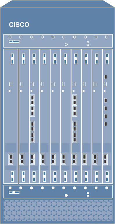
The Cisco TelePresence Server MSE 8710 blade is a high-definition-capable Cisco TelePresence Server that has the same interface as a Cisco TelePresence Server 7010. The Cisco TelePresence Server MSE 8710 and its setup in a Cisco Collaboration environment is shown in Figure 11-2.
The Cisco TelePresence Server MSE 8710 blade supports two management modes—locally or remotely managed. When an external device like Cisco TelePresence Conductor controls the MSE 8710 blade, the remotely managed mode is used. In remotely managed mode, most of the configuration resides at the external device.
The capacity of the blade depends on the management mode:
![]() Locally managed mode: This management mode supports 12 full high-definition (1080p30) participants or 24 high-definition (720p30) participants.
Locally managed mode: This management mode supports 12 full high-definition (1080p30) participants or 24 high-definition (720p30) participants.
![]() Remotely managed mode: This management mode supports 12 full high-definition (1080p30) participants, 24 high-definition (720p30) participants, 48 standard-definition (480p30) participants, or 97 low-definition (360p) participants
Remotely managed mode: This management mode supports 12 full high-definition (1080p30) participants, 24 high-definition (720p30) participants, 48 standard-definition (480p30) participants, or 97 low-definition (360p) participants
Note
Non-HD ports are only available in remotely managed mode, where Cisco TelePresence Conductor controls the Cisco TelePresence Server MSE 8710 blade.
You can group up to four 8710 blades in a cluster, resulting in a maximum of 48 full high-definition participants, 96 high-definition participants, or 192 standard-definition participants per cluster. The total number of participants per cluster is limited to 200. The maximum number of participants per conference is limited to 104.
Cisco TelePresence MCU MSE 8510 Feature Blade
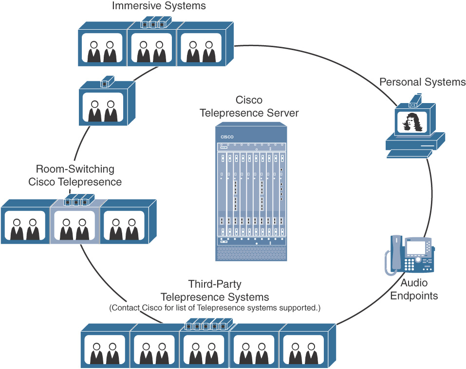
The Cisco TelePresence MCU MSE 8510 blade is a high-definition multimedia Cisco TelePresence Multiparty Conferencing Unit (MCU). Figure 11-3 illustrates an MCU MSE 8510 in a Cisco video conferencing setup.
When locally managed, the TelePresence MCU MSE 8510 can be configured in one of the following modes:
![]() HD mode, which supports 20 video ports with full high-definition (1080p30) or high-definition (720p60) and 20 audio-only ports.
HD mode, which supports 20 video ports with full high-definition (1080p30) or high-definition (720p60) and 20 audio-only ports.
![]() SD mode (448p30), which supports 80 video ports.
SD mode (448p30), which supports 80 video ports.
The mode configuration is a system-wide setting. The whole blade can only be in one mode or the other. If the blade is in HD mode, then each endpoint receives the highest quality that the endpoint supports (up to 1080p30), but regardless of the quality that is actually used, one of the 20 high-definition ports is consumed in HD mode. This situation applies to standard-definition participants, to participants that are only capable of low resolution (360p), and to audio-only participants.
Because of this limitation, a single audio-only conference with 20 participants occupies a full Cisco TelePresence MSE 8510 MCU blade when the multipoint control unit is in HD mode. If you want to support endpoints with different capabilities in a more efficient way, use Cisco TelePresence Conductor for remotely managed mode, which allows better resource utilization of Cisco TelePresence MCUs.
Up to three Cisco TelePresence MCU MSE 8510 blades can be grouped into a cluster that provides 60 high-definition ports and 60 audio-only ports or 240 standard-definition ports per cluster. When nine blades are in a Cisco TelePresence MCU MSE 8000 chassis, up to 180 high-definition and 180 audio-only ports or up to 720 standard-definition ports are available.
If you need more than 60 participants in a single conference, you can cascade two conferences that reside on different clusters. Cascading means that one conference must call the other conference (by its conference number).
Cisco TelePresence ISDN MSE 8321 Feature Blade
The Cisco TelePresence ISDN GW MSE 8321 is a high-capacity and scalable blade. It provides seamless integration between IP and ISDN networks with feature transparency offering high-definition video conferencing for organizations using ISDN. Figure 11-4 shows the Cisco TelePresence ISDN MSE 8321 Feature Blade in action.
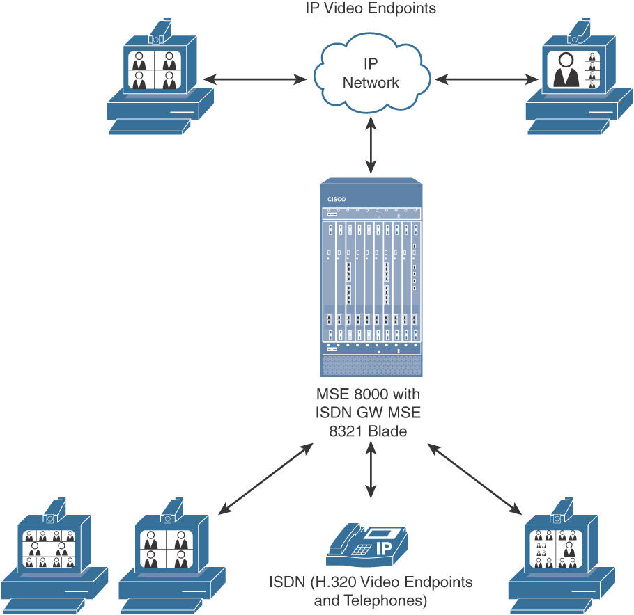
The Cisco TelePresence ISDN MSE 8321 feature blade has following features:
![]() H.239 for presentation-sharing capabilities
H.239 for presentation-sharing capabilities
![]() Video resolutions up to high definition 720p at 30fps
Video resolutions up to high definition 720p at 30fps
![]() Support for up to 8 PRI ISDN ports in a single blade and up to 72 PRI ISDN ports in a single chassis
Support for up to 8 PRI ISDN ports in a single blade and up to 72 PRI ISDN ports in a single chassis
![]() Support for up to 240 voice calls at 64 Kbps per blade and up to 120 video calls at 128 Kbps per blade
Support for up to 240 voice calls at 64 Kbps per blade and up to 120 video calls at 128 Kbps per blade
![]() Bandwidth per call from 56 Kbps to 2 Mbps
Bandwidth per call from 56 Kbps to 2 Mbps
Note
A maximum of eight Cisco TelePresence ISDN GW MSE 8321 blades can be supported in one Cisco TelePresence MSE 8000 chassis. The remaining ninth slot can be used by any other feature blade.
Cisco TelePresence Serial MSE 8330 Feature Blade
Cisco TelePresence Serial MSE 8330 allows transparent integration between IP and serial video conferencing networks. This blade is highly scalable, offering feature transparency and powerful dial-plan capabilities. It allows organizations using networks attached through serial interfaces leverage the benefits from IP-based HD video conferencing solutions. Figure 11-5 shows a Cisco TelePresence Serial MSE 8330 Feature Blade as broker between the serial and IP networks.
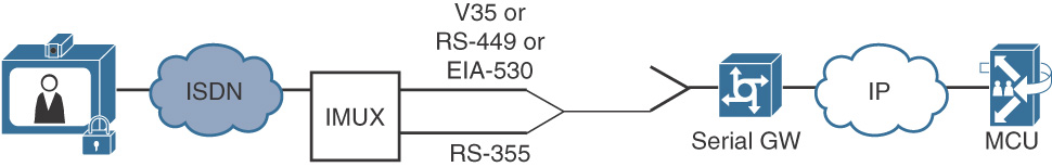
The Cisco TelePresence Serial MSE 8330 feature blade has following key characteristics:
![]() Offers video resolutions up to HD 720p at 30 fps
Offers video resolutions up to HD 720p at 30 fps
![]() Supports up to 16 serial ports in a single blade and up to 144 serial ports in a single chassis
Supports up to 16 serial ports in a single blade and up to 144 serial ports in a single chassis
![]() Supports up to 16 video calls at 1920 kbps each, per blade
Supports up to 16 video calls at 1920 kbps each, per blade
![]() Supports bandwidth per call from 56 to 1920 kbps
Supports bandwidth per call from 56 to 1920 kbps
The next section describes Cisco TelePresence MSE 8000 configuration.
Cisco TelePresence MSE 8000 Feature Blade Configuration
This section explains how to enable access to Cisco TelePresence MSE 8000 feature blades. After you install the Cisco TelePresence MSE 8000 Series chassis and supervisor blade, you can configure the other feature blades in the chassis by using the supervisor web interface.
To access the web interface, follow these steps:
Step 1. Navigate to http://<IP address of the supervisor module>.
Step 2. Log into the system with a valid administrator username and password.
Step 3. From the navigation pane, click the Hardware tab. The Blades window is displayed, which lists the available feature blades.
Step 4. In the Type column, configure the IP address of the applicable feature blade.
Step 5. Click the IP address of a feature blade to connect to the user interface of the feature blade. The user interface of the feature blade depends on the type of feature blade (Cisco TelePresence Server or Cisco TelePresence MCU user interface).
Cisco Telepresence Server
The Cisco TelePresence Server is a transcoding device that offers flexible video, audio, and content-sharing capabilities for multiparty videoconferencing. The Cisco TelePresence Server can be integrated with the following video call control platforms:
![]() CUCM
CUCM
![]() Cisco TelePresence Video Communication Server (VCS)
Cisco TelePresence Video Communication Server (VCS)
The integration can be either direct or via Cisco TelePresence Conductor.
The following is a list of supported platforms for the Cisco TelePresence Server:
![]() The Cisco TelePresence Server on Virtual Machine runs on the Cisco Unified Communications System or third-party specification-based server platforms. This option offers a virtualized solution.
The Cisco TelePresence Server on Virtual Machine runs on the Cisco Unified Communications System or third-party specification-based server platforms. This option offers a virtualized solution.
![]() The Cisco TelePresence Server on Cisco Multiparty Media 310 and Cisco Multiparty Media 320 is an entry-level appliance solution that can be stacked for more capacity.
The Cisco TelePresence Server on Cisco Multiparty Media 310 and Cisco Multiparty Media 320 is an entry-level appliance solution that can be stacked for more capacity.
![]() The Cisco TelePresence Server on Cisco TelePresence Server MSE 8710 is a chassis-based platform that is ideal for large enterprises and service providers that require a high-availability and highly scalable solution. The Cisco TelePresence Server 7010 is a standalone appliance with the same characteristics.
The Cisco TelePresence Server on Cisco TelePresence Server MSE 8710 is a chassis-based platform that is ideal for large enterprises and service providers that require a high-availability and highly scalable solution. The Cisco TelePresence Server 7010 is a standalone appliance with the same characteristics.
![]() The Cisco TelePresence Server can also run on the Cisco TelePresence MCU MSE 8510 and on the Cisco TelePresence MCU 5300 Series platforms, with the appropriate license upgrade. These platforms usually run the Cisco TelePresence MCU application but can be changed to using the Cisco TelePresence Server application.
The Cisco TelePresence Server can also run on the Cisco TelePresence MCU MSE 8510 and on the Cisco TelePresence MCU 5300 Series platforms, with the appropriate license upgrade. These platforms usually run the Cisco TelePresence MCU application but can be changed to using the Cisco TelePresence Server application.
Note
Feature support varies per platform.
Cisco TelePresence Server Licensing
This section describes the two license models available for Cisco TelePresence Server.
Table 11-1 shows the differences between Cisco Personal Multiparty and a screen license model.
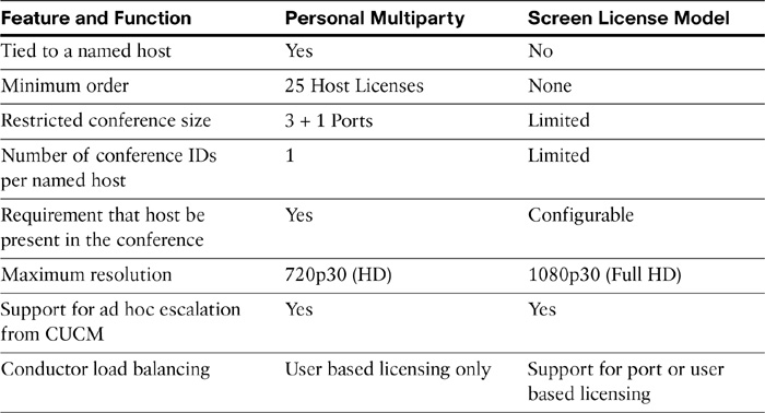
Cisco Personal Multiparty is available within the Cisco Unified Workspace Licensing Professional package. For each license selected, one named host is entitled to provide multiparty meetings with up to three more parties, using a personalized contact address.
In the screen license model for the TPS 7010, one license enables one 1080p30 screen plus content sharing or two 720p30 screens plus content sharing. The maximum Cisco TelePresence Server capacity is achieved with 12 screen licenses. Twelve screen licenses support twelve 1080p30, twenty-four 720p30, forty-eight 480p30, or ninety-seven 360p30 screens.
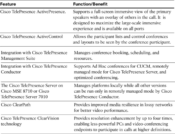
Cisco TelePresence Server Features
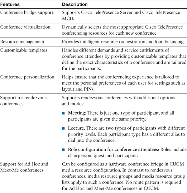
Cisco TelePresence Server offers the features shown in Table 11-2.
Table 11-2 Cisco TelePresence Server Features
Options for Integrating Cisco TelePresence Server with Cisco Unified Communications Manager
This section describes the options for integrating Cisco TelePresence Server with CUCM.
A Cisco TelePresence Server cannot be configured as a hardware conference bridge in CUCM. Therefore, the only way to support Ad Hoc and Meet-Me conferences on Cisco TelePresence Server is to control the Cisco TelePresence Server via Cisco TelePresence Conductor. Cisco TelePresence Conductor must be added as a hardware conference bridge media resource in such a scenario.
Rendezvous conferences can be supported directly by the Cisco TelePresence Server or via Cisco TelePresence Conductor. However, not all Cisco TelePresence Server platforms can be integrated with CUCM for rendezvous conferencing. For example, a virtualized Cisco TelePresence Server cannot be directly integrated with CUCM for rendezvous conferencing.
A Cisco TelePresence Server is in locally managed mode when it interacts directly with CUCM to support rendezvous conferences. Rendezvous conferences can also be provided via Cisco TelePresence Conductor in remotely managed mode. Ad Hoc and Meet-Me conferences are only supported in remotely managed mode.
These Cisco TelePresence Servers are supported by Cisco TelePresence Conductor:
![]() Cisco TelePresence Server 7010 version 3.0(2.46) or later version
Cisco TelePresence Server 7010 version 3.0(2.46) or later version
![]() Cisco TelePresence Server MSE 8710 version 3.0(2.46) or later version
Cisco TelePresence Server MSE 8710 version 3.0(2.46) or later version
![]() Cisco TelePresence Server version 3.1 or later version on Virtual Machine
Cisco TelePresence Server version 3.1 or later version on Virtual Machine
![]() Cisco TelePresence Server version 3.1 on Multiparty Media 310/320
Cisco TelePresence Server version 3.1 on Multiparty Media 310/320
Rendezvous Call Flow with the Cisco TelePresence Server
This section shows the call flow when a rendezvous conference is initiated in an environment where the Cisco TelePresence Server is directly integrated with CUCM.
The following steps describe the call flow for rendezvous conferences.
Step 1. An endpoint dials a rendezvous conference number.
Step 2. CUCM matches a route pattern that points to a route list or an SIP trunk that refers to the Cisco TelePresence Server.
Step 3. CUCM routes the call to the Cisco TelePresence Server via an SIP trunk.
Step 4. The Cisco TelePresence Server matches the called number to a conference numeric ID.
Step 5. The Cisco TelePresence Server starts the conference.
Step 6. The Cisco TelePresence Server accepts the call that was received from CUCM.
Integrating Cisco TelePresence Server and Cisco Unified Communications Manager (CUCM)
This section describes how to integrate a Cisco TelePresence Server with CUCM. The Cisco TelePresence Server must be in locally managed mode to integrate directly with CUCM.
A Cisco TelePresence Server can be integrated with CUCM to support rendezvous video conferencing. Rendezvous conferences are supported only when a Cisco TelePresence Server is directly integrated with CUCM. Rendezvous conferences require a route pattern and an SIP trunk to be configured in CUCM. Ad Hoc and Meet-Me conferences are not supported when a Cisco TelePresence Server is directly integrated with CUCM. Scheduled conferences can be managed via Cisco TelePresence Management Suite (TMS) or directly through the Cisco TelePresence Server user interface.
Note
A Cisco TelePresence Server that is used for scheduled conferences should not be used for rendezvous conferences in order to guarantee port availability for scheduled calls. Deploy separate, dedicated Cisco TelePresence Servers if you want to provide both scheduled conferences and rendezvous conferences.
Cisco TelePresence Server Configuration
The following steps show the Cisco TelePresence Server configuration:
Step 1. Log into the web page of the Cisco TelePresence Server as an administrator and go to Network > DNS. Configure the DNS settings.
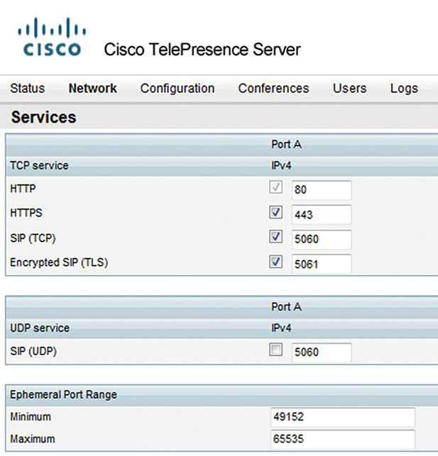
Step 2. Go to Network > Services and check the Services. Enable Hypertext Transfer Protocol Secure (HTTPS) and disable SIP (UDP), as shown in Figure 11-6.
Note
To avoid longer delays in the detection of unresponsive peers, it is highly recommended to use SIP over Transmission Control Protocol (TCP) instead of SIP over User Datagram Protocol (UDP).
Step 3. Choose Configuration > Time and configure the (NTP) Host with the IP address of the NTP server. Ensure that the network time is synced.
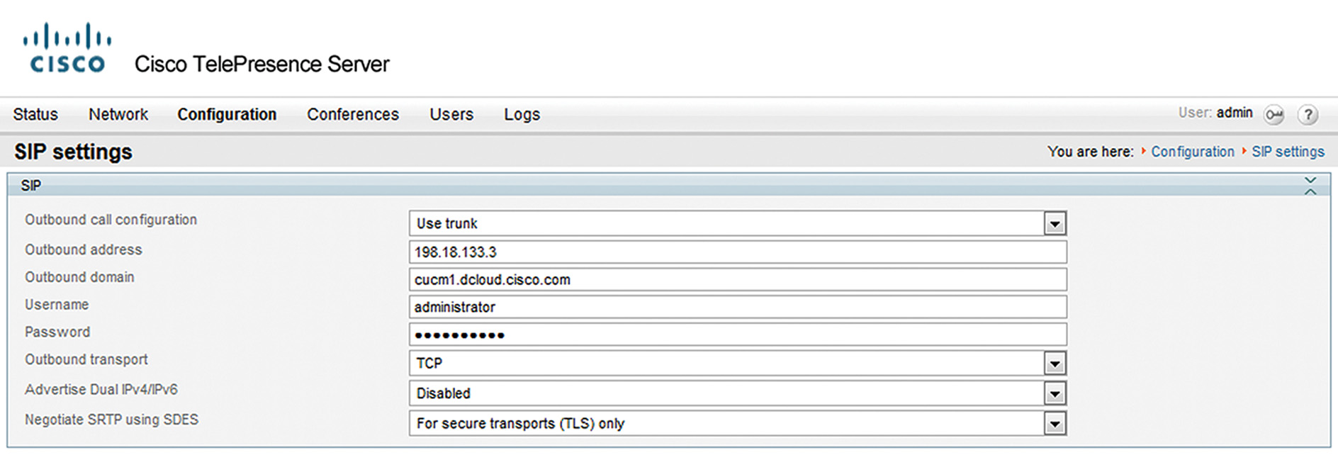
Step 4. Choose Configuration > SIP Settings and click Use Trunk in the Outbound Call Configuration drop-down list. Enter the IP address of the CUCM in the Outbound Address. In the Outbound Domain field, enter the CUCM hostname or IP address that is configured in CUCM (under CUCM Administration GUI > System > Server) as shown in Figure 11-7.
Step 5. Proceed to Conferences > Add New Conference. Enter the conference name in the Name and the ID in the Numeric ID fields respectively.
Note
The numeric ID must match the conference number that is dialed by the endpoint and then sent from the CUCM to the Cisco TelePresence Server via the SIP trunk.
Cisco Unified Communications Manager Configuration
This section describes CUCM configuration for integration with a Cisco TelePresence Server.
The following steps describe CUCM configuration for integration with a Cisco TelePresence Server.
Step 1. Go to the CUCM Administration GUI, go to Device > Trunk, and create an SIP trunk. Enter the Device Name and click the device pool in the Device Pool drop-down list.
Note
If you want to selectively choose nodes of a CUCM cluster, apply the corresponding Unified CM Group to the SIP trunk via the device pool. If you want to use all nodes of the cluster, check the Run On All Active Unified CM Nodes check box.
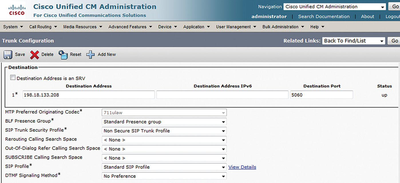
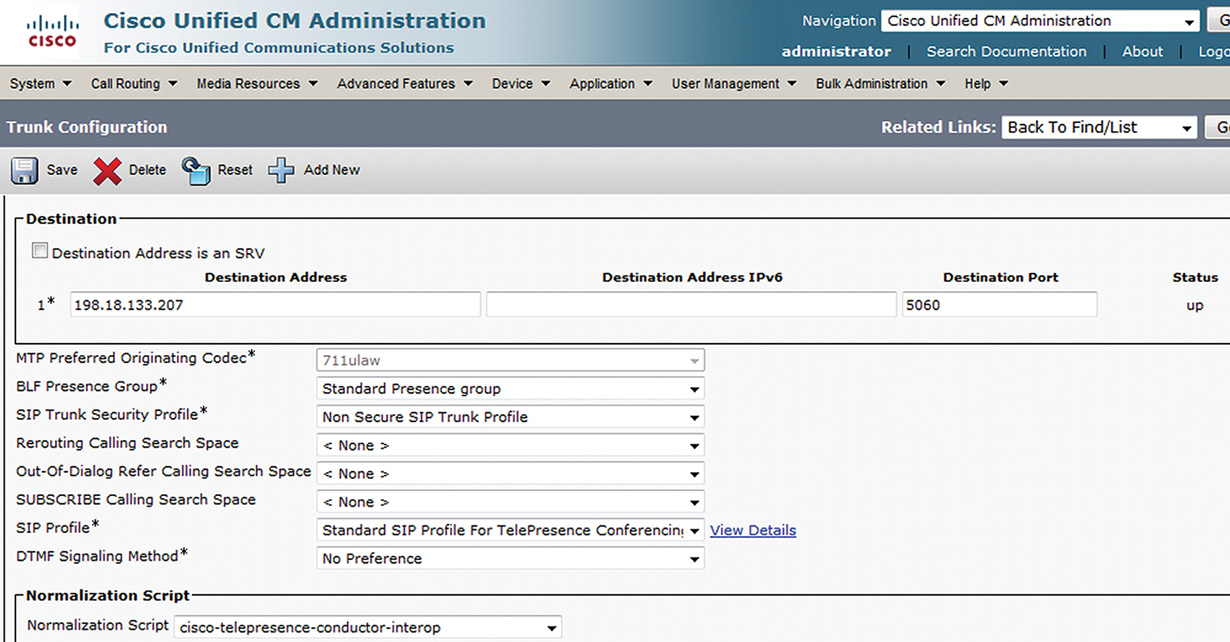
Step 2. Under SIP Information > Destination Address, enter the IP address as shown in Figure 11-8 and set:
![]() SIP Trunk Security Profile as Non Secure SIP Trunk Profile
SIP Trunk Security Profile as Non Secure SIP Trunk Profile
![]() SIP Profile as Standard SIP Profile for TelePresence Conferencing
SIP Profile as Standard SIP Profile for TelePresence Conferencing
Step 3. To route rendezvous calls to Cisco TelePresence, a route pattern is required. Go to Call Routing > Route/Hunt > Route Pattern and create a route pattern that points to the SIP trunk configured in Step 2. In the Route Pattern field, enter the route pattern that matches the pattern that is configured as the conference numeric ID at the Cisco TelePresence Server.
Note
If you do not want to allow all devices to call the rendezvous conference number, apply a partition to the route pattern and then implement calling search spaces (CSSs) as needed.
Cisco TelePresence Conductor
Cisco TelePresence Server and Cisco TelePresence MCU are high-performance and scalable conferencing resources, but they do have some limitations regarding consolidated management, optimal license utilization, and integration support with CUCM. Cisco TelePresence Conductor is a platform that solves these issues by simplifying and enhancing management of Cisco TelePresence conferencing resources. Figure 11-9 gives an overview of Cisco TelePresence Conductor and its place in the Cisco Collaboration network.
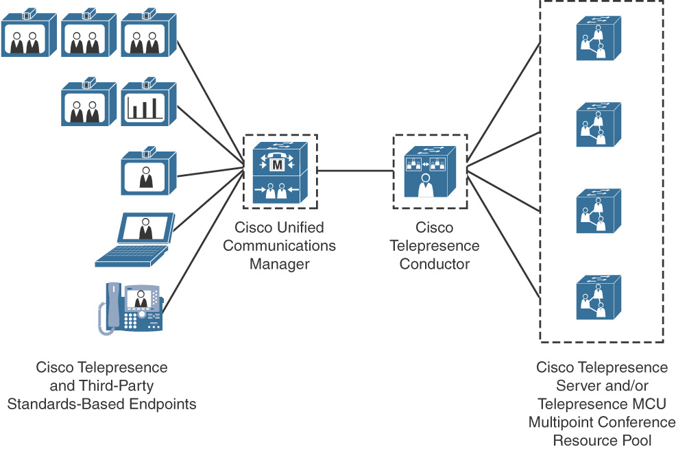
As seen in Figure 11-9, Cisco TelePresence Conductor simplifies multiparty video communications by orchestrating the different resources that are needed for each conference. Cisco TelePresence Conductor simplifies and enhances conference resource management, and makes conferences easy to join and administer. It uses knowledge of all available conferencing resources and their capabilities to help ensure dynamic and intelligent conference placement and optimum resource usage.
The Cisco TelePresence Conductor works with the following video call control platforms:
![]() CUCM
CUCM
![]() Cisco VCS
Cisco VCS
Cisco TelePresence Conductor is available as a dedicated appliance and as a virtualized application that runs on Cisco Unified Computing System (Cisco UCS) platforms or third-party server platforms. The appliance has four 10/100/1000 BASE-TX Ethernet ports, and one RS-232 console port. Each Cisco TelePresence Conductor supports up to 30 Cisco TelePresence MCUs or Cisco TelePresence Servers for up to 2400 calls. For even greater resilience, up to three Cisco TelePresence Conductors can be stacked in a cluster.
Cisco TelePresence Conductor Licensing
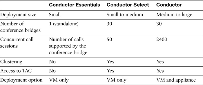
Three types of licenses are supported on Cisco Telepresence Conductor. Depending on the deployment size, the following license options are available:
![]() Cisco TelePresence Conductor Essentials: Cisco TelePresence Conductor software can be downloaded as a virtualized application and installed without a license key in a limited-capacity mode. This license option enables conference resource orchestration for a single, standalone Cisco TelePresence Server or Cisco TelePresence MCU.
Cisco TelePresence Conductor Essentials: Cisco TelePresence Conductor software can be downloaded as a virtualized application and installed without a license key in a limited-capacity mode. This license option enables conference resource orchestration for a single, standalone Cisco TelePresence Server or Cisco TelePresence MCU.
![]() Cisco TelePresence Conductor Select: For small to medium-sized deployments, a license key is available that enables support for up to 50 concurrent calls. This license option enables conference resource orchestration for more than one Cisco TelePresence Server and Cisco TelePresence MCU. Two medium-sized Cisco TelePresence Conductor virtual machines supporting up to 50 concurrent call sessions can be configured as a cluster to provide resilience.
Cisco TelePresence Conductor Select: For small to medium-sized deployments, a license key is available that enables support for up to 50 concurrent calls. This license option enables conference resource orchestration for more than one Cisco TelePresence Server and Cisco TelePresence MCU. Two medium-sized Cisco TelePresence Conductor virtual machines supporting up to 50 concurrent call sessions can be configured as a cluster to provide resilience.
![]() Cisco TelePresence Conductor: For larger deployments, a full-capacity version of Cisco TelePresence Conductor is required. Up to 2400 concurrent calls or up to 30 Cisco TelePresence Servers or Cisco TelePresence MCUs are supported by one full-capacity Cisco TelePresence Conductor appliance or cluster. Up to three full-capacity Cisco TelePresence Conductors can be clustered to provide resilience.
Cisco TelePresence Conductor: For larger deployments, a full-capacity version of Cisco TelePresence Conductor is required. Up to 2400 concurrent calls or up to 30 Cisco TelePresence Servers or Cisco TelePresence MCUs are supported by one full-capacity Cisco TelePresence Conductor appliance or cluster. Up to three full-capacity Cisco TelePresence Conductors can be clustered to provide resilience.
Note
The version of Cisco TelePresence Conductor is determined by the installed license keys (option keys and release keys).
Table 11-3 gives an overview of Cisco TelePresence Conductor licensing options.
Table 11-3 Cisco TelePresence Conductor License Options
Cisco TelePresence Conductor Features
This section describes the features of Cisco TelePresence Conductor. Table 11-4 illustrates the main features that are provided by Cisco TelePresence Conductor.
Table 11-4 Features and Benefits of Cisco TelePresence Conductor
Options for Integrating Cisco TelePresence Conferencing Resources
This section describes the options for integrating Cisco TelePresence conferencing resources and CUCM when using Cisco TelePresence Conductor.
A Cisco TelePresence MCU can be configured as a hardware conference bridge in CUCM to support Ad Hoc and Meet-Me conferences. In this scenario, the Cisco TelePresence MCU is seen as a CUCM media resource. No route pattern is required.
The same implementation option can be achieved by configuring Cisco TelePresence Conductor as the hardware conference bridge media resource in CUCM and then associating the Cisco TelePresence MCU with Cisco TelePresence Conductor. The advantages of such a configuration include centralized management of Cisco TelePresence MCUs and more efficient license utilization.
CUCM can use a Cisco TelePresence MCU for rendezvous conferences. From the CUCM perspective, a rendezvous conference is not a conference, but calls that are placed to the conference number of the rendezvous conference are routed like any other call. No media resource is configured in CUCM, but a route pattern and an SIP trunk are required. The SIP trunk points directly to the Cisco TelePresence MCU or to the Cisco TelePresence Conductor, which then controls the Cisco TelePresence MCU.
A Cisco TelePresence MCU is in locally managed mode when it interacts directly with CUCM. The Cisco TelePresence MCU interacts directly with CUCM as a hardware conference bridge media resource to support CUCM Ad Hoc and Meet-Me conferences or as an SIP peer to support rendezvous conferences.
A Cisco TelePresence MCU is in remotely managed mode when it is controlled by Cisco TelePresence Conductor. In such a deployment, the Cisco TelePresence MCU does not directly communicate with CUCM.
When CUCM is not integrated with Cisco TelePresence Conductor, separate Cisco TelePresence MCUs are required to support Ad Hoc, Meet-Me, and rendezvous conferences. When CUCM is integrated with Cisco TelePresence Conductor, requests for Ad Hoc, Meet-Me, and rendezvous conferences are received by the Cisco TelePresence Conductor and can be passed on to a single Cisco TelePresence MCU.
The following Cisco TelePresence MCUs are supported by Cisco TelePresence Conductor:
![]() Cisco TelePresence MCU 4200 Series version 4.2 or later version
Cisco TelePresence MCU 4200 Series version 4.2 or later version
![]() Cisco TelePresence MCU 4500 Series version 4.2 or later version
Cisco TelePresence MCU 4500 Series version 4.2 or later version
![]() Cisco TelePresence MCU 5300 Series version 4.3(2.17) or later version
Cisco TelePresence MCU 5300 Series version 4.3(2.17) or later version
![]() Cisco TelePresence MCU MSE 8420 version 4.2 or later version
Cisco TelePresence MCU MSE 8420 version 4.2 or later version
![]() Cisco TelePresence MCU MSE 8510 version 4.2 or later version
Cisco TelePresence MCU MSE 8510 version 4.2 or later version
Ad Hoc and Rendezvous Call Flows with Cisco TelePresence Conductor
The following sections describe the Ad Hoc conference and rendezvous conference call flows when Cisco TelePresence Conductor is integrated with Cisco TelePresence and CUCM.
Ad Hoc or Meet-Me Call Flow with Cisco TelePresence Conductor
This section describes the call flows when an Ad Hoc or Meet-Me conference is set up via Cisco TelePresence Conductor, and is illustrated in the following steps.
Step 1. Once a call from one endpoint to another is connected, the caller or called party can tap the Add+ button and call a third endpoint, followed by tapping the Merge or Join button to connect all parties
Step 2. Alternatively, an endpoint can join a Meet-Me conference by using join function.
Step 3. While the conference is being requested, CUCM checks the Media Resource Group List (MRGL) of the endpoint that initiates the conference and allocates Cisco TelePresence Conductor as the media resource for the conference.
Step 4. CUCM sends a request for a conference bridge to the Cisco TelePresence Conductor via the SIP trunk.
Step 5. Cisco TelePresence Conductor accepts the request and creates a conference.
Step 6. The call is routed to the allocated conference bridge, and an Instant Meeting is established.
In Cisco TelePresence Conductor, the conference is allocated as shown in the following steps:
Step 1. Cisco TelePresence Conductor uses a conference template to obtain parameters that will be applied to the conference. In the conference template, the service preference is also configured.
Step 2. The configured service preference is used to select a conference bridge pool based on configured priorities.
Step 3. The selected conference bridge pool is used to search for a conference bridge.
Step 4. The first available conference bridge of the pool is used to create the conference.
Rendezvous Call Flow with Cisco TelePresence Conductor
This section describes the call flow when a rendezvous conference is set up via Cisco TelePresence Conductor. The call flow is as follows:
Step 1. An endpoint dials a rendezvous conference number.
Step 2. CUCM matches a route pattern, which refers to an SIP trunk. The SIP trunk points to Cisco TelePresence Conductor.
Step 3. CUCM routes the call to the Cisco TelePresence Conductor via an SIP trunk.
Step 4. Cisco TelePresence Conductor matches the called number to a conference alias and creates a conference.
Step 5. The call is routed to the conference bridge.
In Cisco TelePresence Conductor, the conference is allocated as shown in the following steps:
Step 1. Cisco TelePresence Conductor matches the called number to a configured conference alias pattern.
Step 2. Cisco TelePresence Conductor uses the parameters of a conference template to create a conference.
Step 3. The service preference that is configured in the conference template is used to select a conference bridge pool based on the configured priorities.
Step 4. The conference bridge pool is used to select an available conference bridge for the conference.
Step 5. The conference is created on the selected conference bridge.
Note
The conference template can contain auto-dialed participants that are automatically added to the conference. This ability is often used when conference recording is needed for a particular rendezvous conference.
You can confirm that Conductor is able to dynamically create a new permanent meeting. While in the call, go to the Conductor and login as administrator. Proceed to Status > Conferences. Expand the meeting and observe the information available in Conductor.
Alternatively, you can also view the conference details via Cisco TelePresence Server. Go to the Cisco TelePresence Server GUI and log in as administrator. Go to Conferences > Conferences and click on the active meeting. Click Expand all to see live screenshots of the send and receive video streams.
Integrating Cisco TelePresence Conductor and Cisco Unified Communications Manager
This section covers integration of the Cisco TelePresence Server, TelePresence Conductor, and CUCM to support Ad Hoc and rendezvous conferencing.
Cisco TelePresence Server Configuration
This section covers the configuration of Cisco TelePresence Server for integration with Cisco TelePresence Conductor.
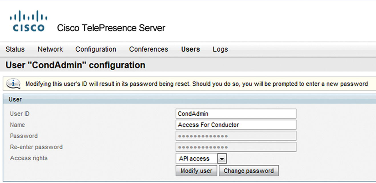
Step 1. For the TelePresence Conductor to communicate with the TelePresence Server, it uses credentials for a user account that has administrator rights. Go to Cisco TelePresence GUI and go to Users > Add new user and click New. Add a user with API access as shown in Figure 11-10.
Step 2. Go to Network > Services. Check the box next to 443 and and click Apply changes.
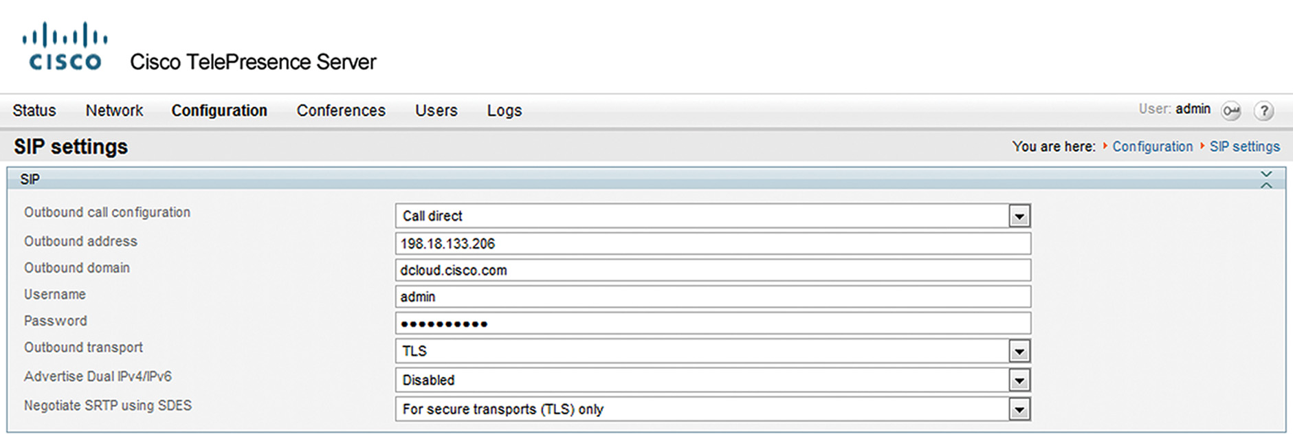
Step 3. Go to Configuration > SIP settings and configure Outbound address as address for Conductor, Outbound domain, and Outbound Transport as TLS as shown in Figure 11-11. Click Apply changes.
At this time, the Cisco TelePresence Server is configured for integration with Cisco TelePresence Conductor. The next section describes Cisco TelePresence Conductor configuration for integration with the Cisco TelePresence Server and CUCM.
Cisco TelePresence Conductor Configuration
This section describes Cisco TelePresence Conductor configuration.
Follow these steps to configure the Cisco TelePresence Conductor to support Ad Hoc and rendezvous conferences.
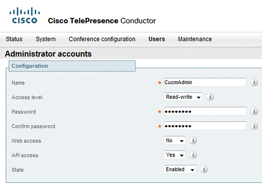
Step 1. Go to Conductor GUI and proceed to Users > Administrator accounts. Click New. Define a user for CUCM to communicate with the TelePresence Conductor as shown in Figure 11-12. Provide the Name, Access level (must be Read-Write), and Password, then set Web Access to No. Click Save.
Step 2. Set up the system DNS and NTP by browsing to System > DNS and System > Time respectively. Ensure that Network Time is synchronized.
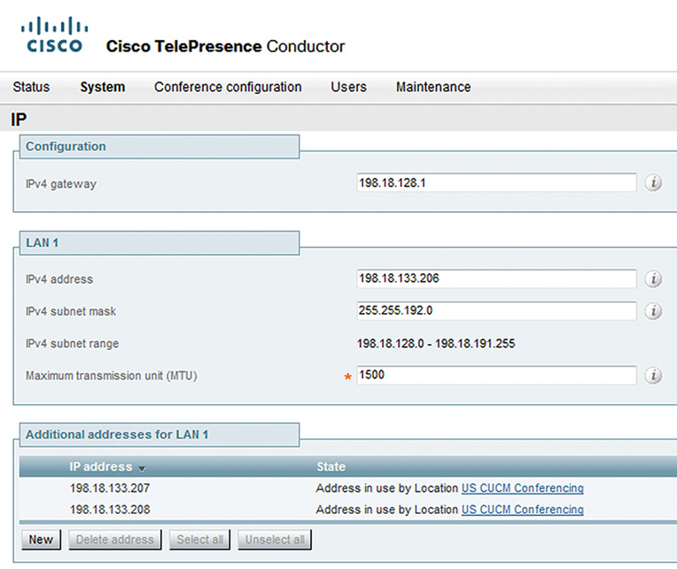
Step 3. Conductor needs additional IP addresses that will be associated with the Ad Hoc (instant meeting) and rendezvous (permanent meeting) conferences.
To configure the second and third Network Interface Cards (NICs), go to System > IP and under Additional address for LAN 1 click New. Provide second and third IP addresses as shown in Figure 11-13.
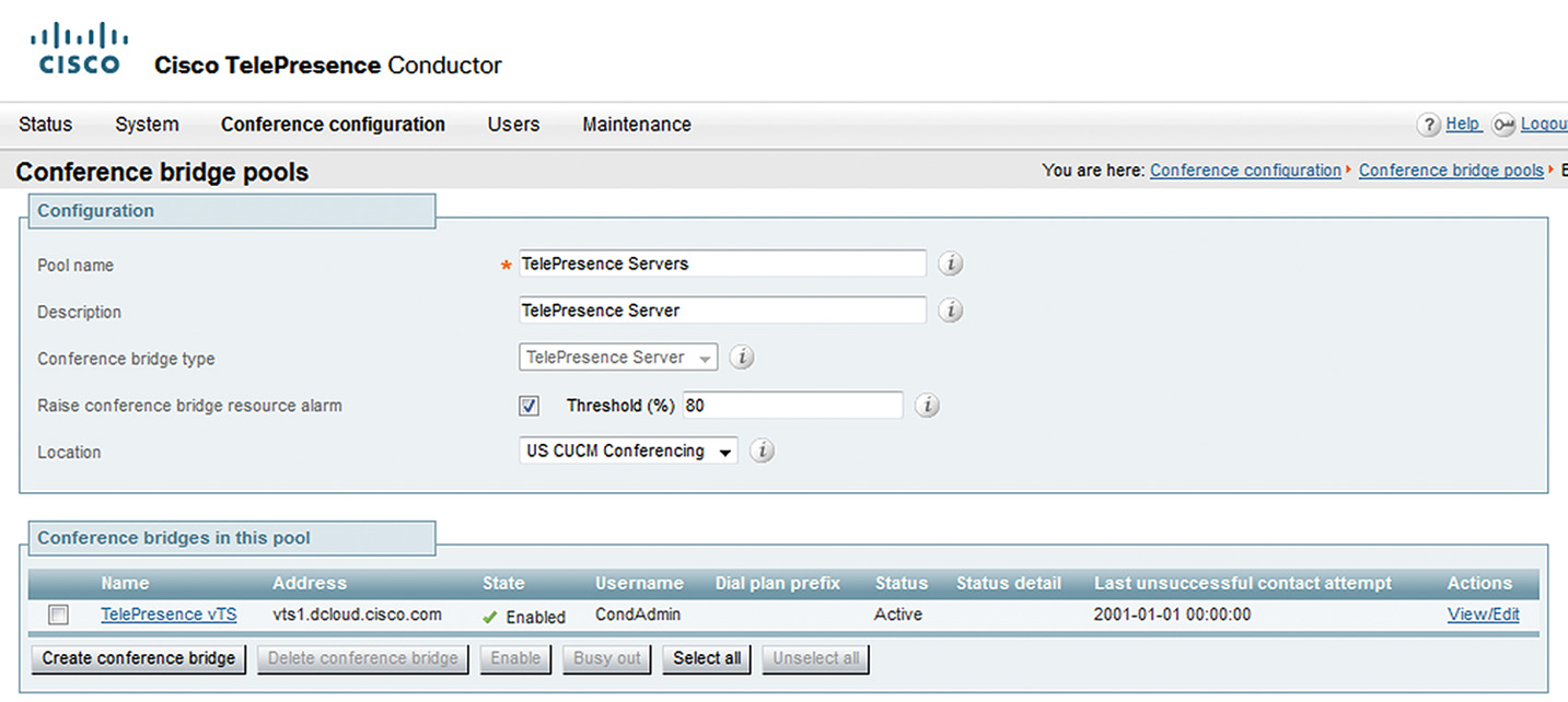
Step 4. Go to Conference configuration > Conference bridge pools and click New. Define the Pool name and set the Conference bridge type as TelePresence Server, as shown in Figure 11-14. Click Create pool.
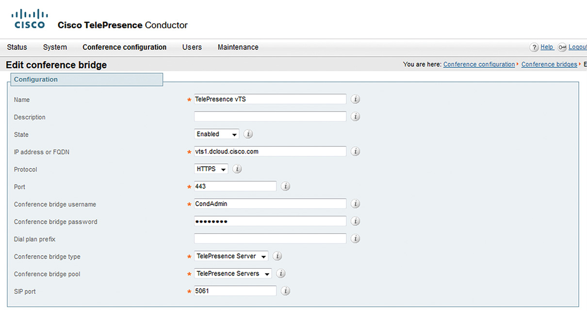
Step 5. Click Create conference bridge to add the conference bridge to the newly created TelePresence Server’s bridge pool as illustrated in Figure 11-15. Click Create conference bridge.
Note
Once the conference bridge is defined, ensure that under pool section in the Status column it shows up as Active. For example, the conference bridge TelePresence vTS is listed as Active, as shown in Figure 11-14 in Step 4.
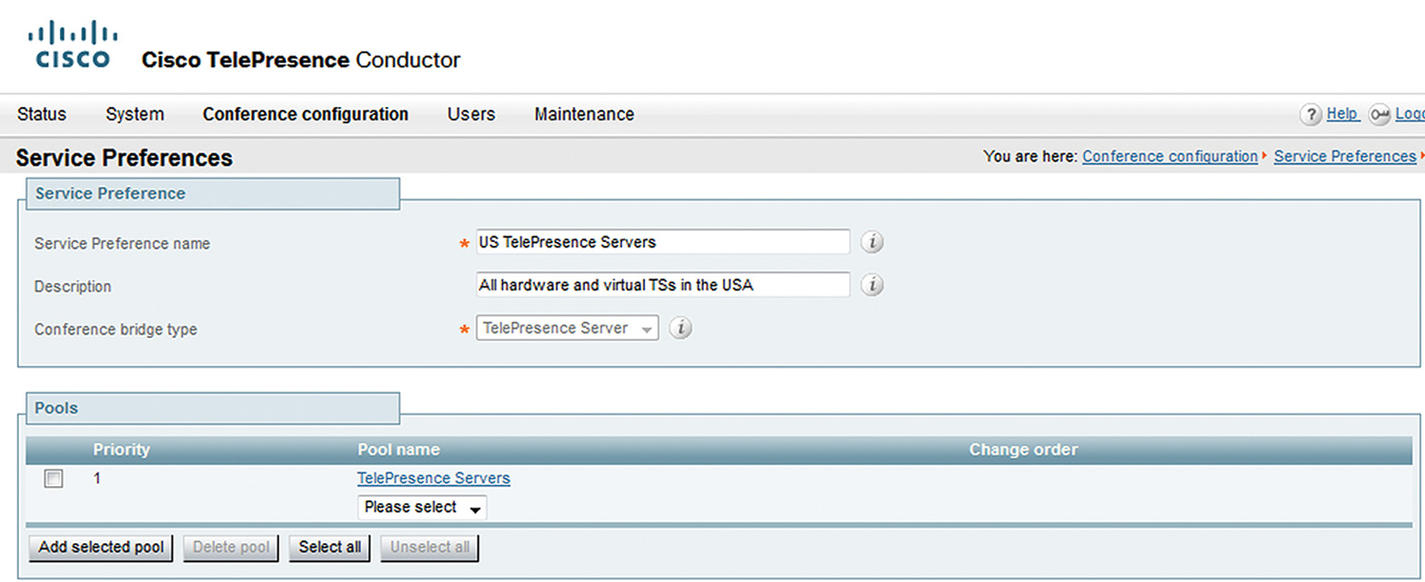
Step 7. Go to Conference configuration > Service Preferences and click New. Provide Service Preference name, Description, and Conference bridge type (set as TelePresence) as shown in Figure 11-16. Click Add Service Preference. Under Pool name, choose TelePresence Servers and click Add selected pool. Click Save.
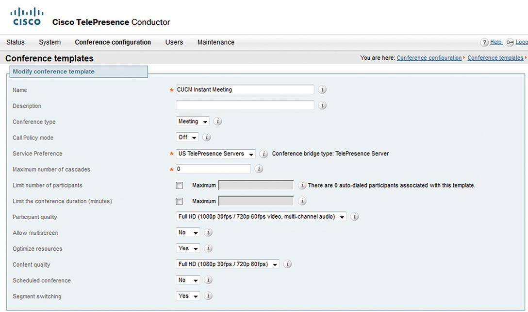
Step 8. Templates are required to define conference configuration parameters. To create an instant meeting template, go to Conference Configuration > Conference templates and click New. As shown in Figure 11-17, enter the Name, Service preference, and Content quality details. Click Create conference template. Click New.
Step 9. To add a permanent conference template, click Create conference template. As in Step 8, define the various parameters. Define the rendezvous conference so it can be recognized by a distinctive name, for example, CUCM Rendezvous Conference.
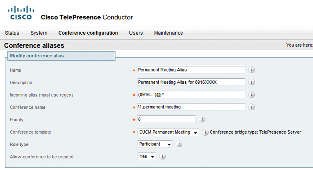
Step 10. To invoke a conference template, a conference alias is required. The conference alias can be a string, SIP URI, or a DN, dialed by the endpoint to get to the conference. Go to Conference configuration > Conference aliases and click New. Provide the Name, Description, Incoming Alias (must use regex), Conference name, and Conference template as shown in Figure 11-18. Click Save.
Note
In an instant meeting escalation, using the join button on the video endpoint escalates a point to point call to a conference with three or more attendees; the conference alias is not used. CUCM tells Conductor the conference alias information for the instant meeting.
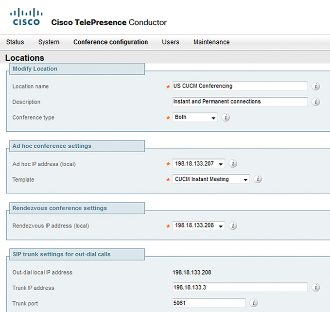
Step 11. Locations are needed to connect to separate conference bridges. Locations correlate different IP addresses to types of calls; for example, 198.18.133.207 was used for Ad Hoc conferences and 192.18.133.208 for rendezvous conferences. To create a location, go to Conference configuration > Locations and click New. Provide information for Location name, Description, Conference type (should be set to Both), Ad hoc IP address (local), Template, Rendezvous IP Address (local), and Trunk IP address as shown in Figure 11-19. Click Add location.
Step 12. Go to Conference configuration > Conference bridge pools, and then click the TelePresence Servers link. Select the Location that was defined in Step 11. Click Save.
Note
This links the bridge pools to the location for Conductor autodial participants.
This completes the Cisco TelePresence Conductor configuration. The next section addresses CUCM configuration for supporting Ad Hoc and rendezvous video conferencing calls.
CUCM Configuration
CUCM can be configured to use one or more SIP trunks to Cisco TelePresence Conductor so different trunks can be used for rendezvous (permanent meeting) and for Ad Hoc (instant meeting) conferences.
Note
Using one or more trunks, CUCM can receive or place voice, video, and encrypted calls; exchange real-time event information; and communicate in other ways with call control servers and other external servers.
Follow these steps to configure CUCM to support Ad Hoc and rendezvous conferences.
Step 1. Go to Device > Trunk and click Add New. The trunk type should be SIP; click Next.
Step 2. Provide a Device Name and Device Pool, and under SIP Information > Destination Address, provide an alternative IP address (configured for LAN 1 in previous section for Ad Hoc/rendezvous conferences), as shown in Figure 11-20:
![]() Set SIP Trunk Security Profile as Non Secure SIP Trunk Profile
Set SIP Trunk Security Profile as Non Secure SIP Trunk Profile
![]() Set SIP Profile as Standard SIP Profile for TelePresence Conferencing
Set SIP Profile as Standard SIP Profile for TelePresence Conferencing
![]() Set Normalization Script as cisco-telepresence-conductor-interop
Set Normalization Script as cisco-telepresence-conductor-interop
Click Save.
Step 3. Define a route pattern for rendezvous (permanent meetings) conferences. Go to Call Routing > Route/Hunt > Route Pattern, and then click Add New. Enter the Route Pattern (for example, 8916XXXX ), and for Gateway/Route List choose the Rendezvous SIP Trunk configured in Step 2.
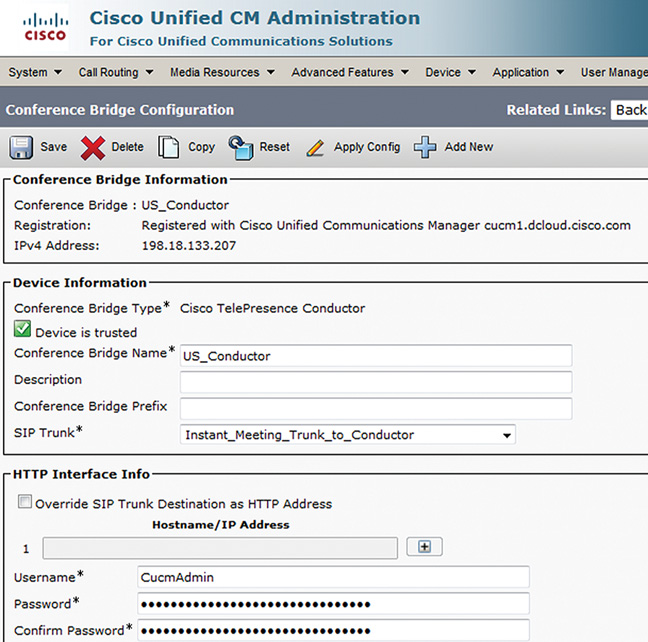
Step 4. Go to Media Resources > Conference Bridge and click Add New. Enter the Conference Bridge Type as Cisco TelePresence Conductor, Conference Bridge Name, SIP Trunk, Username, and Password as shown in Figure 11-21. Click Save.
Step 5. Go to Media Resources > Media Resource Group and create an MRG with the Cisco TelePresence Conductor defined in the previous step. Finally, go to Media Resources > Media Resource Group List to create an MRGL, and add the MRG to it. This MRGL can be assigned to device pool or to the video endpoints.
At this time, Ad Hoc and rendezvous meetings can be established from video endpoints.
Chapter Summary
The following list summarizes the key points discussed in this chapter:
![]() Cisco has a wide portfolio to support video conferencing. This includes the Cisco TelePresence MSE 8000 series (with feature blades), Cisco TelePresence Server with native CUCM integration, Cisco TelePresence Conductor integrated with CUCM and Cisco TelePresence Server, and Cisco TelePresence Management Server–based conferencing.
Cisco has a wide portfolio to support video conferencing. This includes the Cisco TelePresence MSE 8000 series (with feature blades), Cisco TelePresence Server with native CUCM integration, Cisco TelePresence Conductor integrated with CUCM and Cisco TelePresence Server, and Cisco TelePresence Management Server–based conferencing.
![]() The Cisco TelePresence MSE 8000 series offers enterprise-grade video conferencing and options to enterprises with and without IP capabilities.
The Cisco TelePresence MSE 8000 series offers enterprise-grade video conferencing and options to enterprises with and without IP capabilities.
![]() Cisco TelePresence Server is a scalable platform that offers both Ad Hoc (with Cisco TelePresence Conductor) and rendezvous conferencing.
Cisco TelePresence Server is a scalable platform that offers both Ad Hoc (with Cisco TelePresence Conductor) and rendezvous conferencing.
![]() Cisco TelePresence Conductor is an enterprise-grade video conferencing solution that works with Cisco TelePresence Server, Cisco Video Communication Server, and CUCM.
Cisco TelePresence Conductor is an enterprise-grade video conferencing solution that works with Cisco TelePresence Server, Cisco Video Communication Server, and CUCM.
![]() Cisco TelePresence Server direct integration with CUCM supports only rendezvous conferencing.
Cisco TelePresence Server direct integration with CUCM supports only rendezvous conferencing.
![]() Cisco TelePresence Server integration via Cisco TelePresence Conductor supports both Ad Hoc and rendezvous conferencing.
Cisco TelePresence Server integration via Cisco TelePresence Conductor supports both Ad Hoc and rendezvous conferencing.
References
For additional information, refer to the following:
Cisco Systems, Inc. Cisco TelePresence Conductor with Unified CM Deployment Guide, Release XC2.3 & 10.0, http://www.cisco.com/c/dam/en/us/td/docs/telepresence/infrastructure/conductor/config_guide/TelePresence-Conductor-Unified-CM-Deployment-Guide-XC2-3.pdf.
Cisco Systems, Inc. Cisco TelePresence Server 7010 and MSE 8710 V3.0 Locally Managed Mode Deployment Guide, September 2014. http://www.cisco.com/c/dam/en/us/td/docs/telepresence/infrastructure/ts/deployment_guide/Cisco_TelePresence_Server_Deployment_Guide.pdf.
Cisco Systems, Inc. Configuring Video Conferences and Video Transcoding, September 2014. http://www.cisco.com/c/en/us/td/docs/voice_ip_comm/cucme/feature/guide/Video-trans-conf.pdf.
Cisco Systems, Inc. Cisco Collaboration Systems 10.x Solution Reference Network Designs (SRND), May 2014. http://www.cisco.com/c/en/us/td/docs/voice_ip_comm/cucm/srnd/collab10/collab10.html
Review Questions
Use the questions here to review what you learned in this chapter. The correct answers are found in Appendix A, “Answers to the Review Questions.”
1. Which of the following blades offers Full HD conferencing for up to 20 participants resources and acts as a codec translator?
a. 8510
b. 8710
c. Conductor
d. 310
2. Which of the following is the maximum number of HD multipoint participants supported by the MSE 8000?
a. 100
b. 96
c. 700
d. 180
3. What is the highest support bandwidth of the MSE 8000?
a. 10 Mbps
b. 100 Mbps
c. 1 Gbps
d. 10 Gbps
4. Which feature provides greater resiliency in a lossy network?
a. Cisco ClearPath
b. Cisco ClearVision
c. Enhanced QoS
d. ActiveControl
e. Conductor Remote Management
5. Which of the following is required between CUCM and the TelePresence Server?
a. IP tunnel
b. MGCP gateway
c. H.323 gateway
d. SIP trunk
6. True or false? The Cisco TelePresence Server can run in a virtual machine.
a. True
b. False
7. How many calls can a Cisco TelePresence Conductor support?
a. 4000
b. 2400
c. 800
d. 1024
e. 720
8. To set characteristics of the call layout, switching and presentation modes, which of the following should be applied?
a. Layout guides
b. Templates
c. Lecture sets
d. Conference configuration sets
9. True or false? Rendezvous calls are viewed as conferences to CUCM.
a. True
b. False
10. A rendezvous call is pointed to what resource by CUCM in the call routing process?
a. H.323 gateway
b. Device pool
c. Translation pattern
d. Route pattern