Chapter 12. Quality of Service in Cisco Collaboration Solutions
Cisco Collaboration solutions enable users to leverage the power of true collaborative network with voice, video, data, and associated services available on same network. However, when voice and video are converged with data, it is essential to understand the impact of such a mix: that is, the impact on quality of voice/video communications. Voice and video streams are real time and need to be treated differentially compared to data. This is where quality of service (QoS) helps prioritize real-time traffic and overcome a number of traffic flow issues.
Chapter Objectives
Upon completing this chapter, you will be able to meet the following objectives:
![]() Describe the requirements for quality of service by identifying issues affecting packet networks carrying voice and video traffic.
Describe the requirements for quality of service by identifying issues affecting packet networks carrying voice and video traffic.
![]() Describe the need for quality of service in converged networks.
Describe the need for quality of service in converged networks.
![]() Describe the quality of service requirements for voice and video traffic.
Describe the quality of service requirements for voice and video traffic.
![]() Describe classification and marking.
Describe classification and marking.
![]() Describe the DiffServ model.
Describe the DiffServ model.
![]() Describe queuing.
Describe queuing.
![]() Describe traffic policing and shaping.
Describe traffic policing and shaping.
![]() Describe Medianet for video QoS.
Describe Medianet for video QoS.
![]() Describe voice and video traffic bandwidth calculation.
Describe voice and video traffic bandwidth calculation.
An Introduction to Converged Networks
Before the convergence of data and real-time traffic, the focus was on connectivity. With voice and data flows coming together into the network and data trying to utilize as much bandwidth as possible at any given time, voice packets are impacted.
Note
Data traffic is bursty by nature, whereas voice traffic can be consistent (audio) or bursty (video).
Data protocols that were developed as networks proliferated have adapted to the bursty nature of data networks, and brief network congestion is survivable for many types of traffic streams. For example, when you retrieve email, a delay of a few seconds is generally not noticeable. Even a delay of minutes is annoying but not unexpected, and depending on the infrastructure between the endpoints and email servers, is generally not viewed as a critical failure. Furthermore, if a data stream loses a few packets, because of TCP-based connectivity the lost packets can be retransmitted.
On the other hand, as applications such as voice and video became more common, separate networks were built to accommodate the differing traffic flows. Because each application had different traffic characteristics and requirements, network designers deployed nonintegrated networks, such as a data network, and an ISDN network for video traffic. Converged networks bring the traffic together, sharing the same network infrastructure to carry the various data flows.
With the prevalence of converged networks, the demand for quality of service mechanisms is readily apparent as voice and video traffic cannot tolerate delay, jitter and packet loss as they traverse the network. Without these QoS measures, voice and video traffic drops packets, and conversations become useless. There has been an expectation when picking up a phone to have a clear and uninterrupted conversation, and as video conferencing has gained adoption, the same expectation is applied.
Data packets on the other hand, are typically large and can survive delays and drops. It is possible to retransmit part of a dropped data file, but it is not feasible to retransmit a part of a voice or video conversation. Therefore, data traffic is often shaped and set to a lower priority through QoS mechanisms. Since the access for data or voice packets is on a first-come, first-served basis, depending on the number of users, applications, and data or voice flows accessing the network at any given time; voice is susceptible to delay, packet loss, and other issues.
Even a brief network outage on a converged network can seriously disrupt business operations. With inadequate preparation of the network, voice transmission can be choppy to unintelligible. Gaps in speech or video frames are particularly troublesome and noticeable. Silence for audio, and dropped packet frames in video are frustrating to users, and in certain applications cause issues such as in voice-mail systems, where silence is a problem.
Quality of Service Overview
The role and goal of quality of service (QoS) is to provide better and more predictable network service with dedicated bandwidth, controlled jitter and latency, and improved loss characteristics as required by the applications and traffic types. QoS achieves these goals by providing tools for managing network congestion, shaping network traffic, using network segments more efficiently, and setting traffic policies across the network.
Note
QoS is not a substitute for bandwidth. If the network is congested, packets will be dropped. QoS allows for the control of traffic that must be dropped or delayed, and how and when traffic is handled during congestion.
Voice and video over IP traffic (VoIP) consists of two parts: media/bearer traffic and signaling traffic. Media traffic is based on Real-Time Transport Protocol (RTP), which runs on top of User Datagram Protocol (UDP). Signaling traffic is based on a number of protocols, such as Session Initiation Protocol (SIP), Skinny Client Control Protocol (SCCP), H.323 protocol, and Media Gateway Control Protocol (MGCP), and is TCP/UDP based. When an RTP packet is lost, recreating or retransmitting it is neither possible nor worthwhile. As the name suggests, RTP works in real time and is not worth restoring, since missing packets will not make sense when they arrive out of order (not in correct sequence) during a live conversation.
In today’s converged networks where voice, video, and data coexist, it is important to treat voice and video traffic differently from data traffic, which is mostly TCP-based and is easily retransmitted without loss of quality. Quality of service (QoS) enables network administrators to leverage tools for providing special treatment for delay- and time-sensitive traffic such as voice. The network infrastructure must provide classification, policing, and scheduling services for multiple traffic classes.
A QoS policy is a network-wide definition of the specific levels of QoS that are assigned to different classes of network traffic. In a converged network, having a QoS policy is as important as having a security policy. A QoS policy is a definition of the QoS levels that are assigned across a network.
Three basic steps are involved in implementing QoS on a network:
Step 1. Identify traffic and its requirements: Study the network to determine the type of traffic that is running on the network, and then determine the QoS requirements for the different types of traffic.
Step 2. Group the traffic into classes with similar QoS requirements: As an example of these groupings, the voice and video traffic flows are put into dedicated classes with guaranteed bandwidth, and all of the data traffic is put into a best-effort class.
Step 3. Define QoS policies to meet the QoS requirements for each traffic class: Voice traffic is given top priority and is always transmitted first. The video traffic is transmitted after voice but before the best-effort traffic, which is transmitted only when no other traffic is present.
Voice Quality Impacting Factors
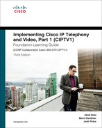
This section explains the various factors that impair the quality of communications on converged networks. Voice and video quality is affected by the following three QoS factors:
![]() Latency (delay): The unwarranted delay in time required for a packet to traverse the network from source to destination
Latency (delay): The unwarranted delay in time required for a packet to traverse the network from source to destination
![]() Jitter (delay variation): Irregular time intervals in the arrival of packets
Jitter (delay variation): Irregular time intervals in the arrival of packets
![]() Packet loss: Packets lost in transit from source to destination due to network congestion, link flapping, or other reasons
Packet loss: Packets lost in transit from source to destination due to network congestion, link flapping, or other reasons
Figure 12-1 depicts the three factors discussed.
Latency (delay) can cause degradation in voice quality. Latency should be kept under 150 ms of one-way or 300 ms round-trip time (RTT) for end-to-end (from mouth to ear) delay to ensures user satisfaction.
Jitter buffers are used to ascertain that variable delays are converted to constant delays. Adaptive jitter buffers can help overcome jitter issues by dynamically tuning the jitter buffer size to the lowest acceptable value.
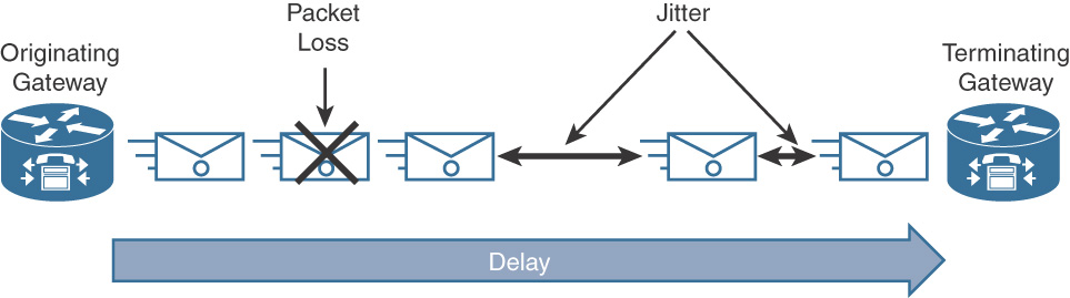
Many sources of delay are introduced both during packet creation and transit from source to destination, as outlined in Table 12-1. Moreover, the delay can be either a fixed delay or a variable delay, depending on where it is introduced. Fixed delay adds to overall delay introduced from source to destination. Variable delay is a function of queues and buffers.
Table 12-1 Sources of Delay During Voice Packet Formation and Transit
Voice and Video Traffic Characteristics and QoS Requirements
This section describes the traffic characteristics and various requirements for voice and video QoS.
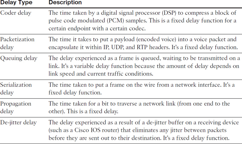
Audio traffic has the following key characteristics:
![]() Bandwidth: Constant bitrate (smooth) with small footprint (small packet size)
Bandwidth: Constant bitrate (smooth) with small footprint (small packet size)
![]() Loss sensitive
Loss sensitive
![]() Delay sensitive
Delay sensitive
Video traffic has following key characteristics:
![]() Bandwidth: Variable bitrate (bursty) with medium/large footprint
Bandwidth: Variable bitrate (bursty) with medium/large footprint
![]() Loss sensitive
Loss sensitive
![]() Delay sensitive
Delay sensitive
Figure 12-2 depicts the audio vs. video traffic relation between bandwidth and time.
Voice (Bearer) Traffic
The following list summarizes the key QoS requirements and recommendations for voice (bearer) traffic:
![]() Voice traffic should be marked to DSCP EF (46) per the QoS baseline and RFC 3246.
Voice traffic should be marked to DSCP EF (46) per the QoS baseline and RFC 3246.
![]() Packet loss should be no more than 1 percent.
Packet loss should be no more than 1 percent.
![]() One-way latency (mouth to ear) should be no more than 150 ms.
One-way latency (mouth to ear) should be no more than 150 ms.
![]() Average one-way jitter should be targeted to be under 30 ms.
Average one-way jitter should be targeted to be under 30 ms.
![]() A range of 21 to 320 kbps of guaranteed priority bandwidth is required per call (depending on the sampling rate, the VoIP codec, and Layer 2 media overhead).
A range of 21 to 320 kbps of guaranteed priority bandwidth is required per call (depending on the sampling rate, the VoIP codec, and Layer 2 media overhead).
![]() 150 bps + Layer 2 overhead guaranteed bandwidth should be provided for voice-control traffic per call.
150 bps + Layer 2 overhead guaranteed bandwidth should be provided for voice-control traffic per call.
Video (Bearer) Traffic
Video traffic can be categorized into three broad categories:
![]() Interactive/IP telephony video (videoconferencing)
Interactive/IP telephony video (videoconferencing)
![]() Streaming video (unicast or multicast)
Streaming video (unicast or multicast)
![]() Immersive video (TelePresence)
Immersive video (TelePresence)
Note
CUCM supports different DSCP markings for immersive video traffic and videoconferencing (IP video telephony) traffic. By default, CUCM has preconfigured the recommended DSCP values for immersive video calls at CS4 and for IP video telephony calls at AF41.
When provisioning for interactive video (video conferencing) traffic, the following guidelines are recommended:
![]() Interactive video traffic should be marked to DSCP AF41
Interactive video traffic should be marked to DSCP AF41
![]() Loss should be no more than 1 percent.
Loss should be no more than 1 percent.
![]() One-way latency should be no more than 150 ms.
One-way latency should be no more than 150 ms.
![]() Jitter should be no more than 30 ms.
Jitter should be no more than 30 ms.
![]() Excess videoconferencing traffic can be marked down by a policer to AF42 or AF43.
Excess videoconferencing traffic can be marked down by a policer to AF42 or AF43.
![]() Assign interactive video to either a preferential queue or a lower priority queue.
Assign interactive video to either a preferential queue or a lower priority queue.
When provisioning QoS for streaming video traffic, follow these guidelines:
![]() Streaming video (whether unicast or multicast) should be marked to DSCP AF31.
Streaming video (whether unicast or multicast) should be marked to DSCP AF31.
![]() Loss should be no more than 5 percent.
Loss should be no more than 5 percent.
![]() Latency should be no more than 4 to 5 seconds (depending on the video application’s buffering capabilities).
Latency should be no more than 4 to 5 seconds (depending on the video application’s buffering capabilities).
![]() There are no significant jitter requirements.
There are no significant jitter requirements.
![]() Guaranteed bandwidth (CBWFQ) requirements depend on the encoding format and rate of the video stream.
Guaranteed bandwidth (CBWFQ) requirements depend on the encoding format and rate of the video stream.
![]() Streaming video applications (unicast or multicast), apart from known sources in an organization, may be marked as Scavenger—DSCP CS1, implemented in the Scavenger traffic class and assigned a minimal bandwidth (CBWFQ) percentage. For example, video from YouTube may be treated this way.
Streaming video applications (unicast or multicast), apart from known sources in an organization, may be marked as Scavenger—DSCP CS1, implemented in the Scavenger traffic class and assigned a minimal bandwidth (CBWFQ) percentage. For example, video from YouTube may be treated this way.
Note
Streaming video applications have more tolerant QoS requirements, as they are not delay sensitive (the video can take several seconds to buffer) and are largely not sensitive to jitter (because of application buffering). However, streaming video might contain valuable content, such as e-learning applications or multicast company meetings, in which case it requires service guarantees.
Call Signaling Traffic
Call signaling traffic originally was marked to DSCP AF31. As defined in RFC 2597, for the assured forwarding classes, flows could be subject to markdown and aggressive dropping of marked-down values. Progressively, the DSCP marking has been changed to CS3 in-line with the QoS baseline marking recommendation for call signaling as defined in RFC 2474. The traffic flows are not subject to aggressive markdown and dropping in this DSCP class. The call signaling traffic protocols, such as SCCP, SIP, MGCP, and H.323, should be marked as DSCP CS3 (or legacy value of DSCP AF31 for backward compatibility).
The next section discusses the QoS deployment architectures.
QoS Implementation Overview
QoS can be implemented via Integrated Services (IntServ) or Differentiated Services (DiffServ) architectures. The IntServ architecture provides QoS by assuring treatment for a specific traffic flow. For example, IntServ has Resource Reservation Protocol (RSVP) as a QoS mechanism where each router on the path for packet transmission is informed of the upcoming packet stream and bandwidth is guaranteed in an end-to-end fashion before a call is setup between the calling and called endpoints.
The DiffServ architecture, on the other hand, differentiates/classifies various types of traffic and provides several levels of service based on that classification. Unlike IntServ, DiffServ labels packets with a particular priority marking that can be referenced by other network devices/applications and hence classified in various traffic classes to be treated accordingly.
To help deploy QoS for Collaboration (and converged) networks, Cisco provides a QoS toolkit composed of the following tools:
![]() Classification and marking
Classification and marking
![]() Traffic policing
Traffic policing
![]() Queuing
Queuing
![]() Traffic shaping
Traffic shaping
Figure 12-3 illustrates the QoS order of operation at a high level.

QoS operation largely depends on QoS policies provisioned in a network. It starts with classification and marking, followed by policing and queuing, and finally shaping and fragmentation. It is essential to plan and deploy end-to-end QoS in LAN, WAN, and virtualized environments to ensure that voice and video quality is acceptable. The sections that follow discuss QoS tools and their application.
Classification and Marking
Classification is the process by which Cisco Collaboration infrastructure devices and applications identify packets or frames and sort traffic into different classes. Before getting into the specifics of classification and marking, it is important to understand the trust boundary concept as well as concepts behind trusted, conditionally trusted, and untrusted devices.
Trust Boundary
Classification is based on various criteria, such as IP address or protocol and port. Moreover, packet or frame (Layer 3 or Layer 2) classification and marking can be carried out based on whether a device is trusted or untrusted (that is, the source of packets/frames; for example, a Cisco Unified IP Phone would be trusted). A device can be defined as a trusted or conditionally trusted device if it can mark or remark packets and can correctly classify traffic. If a device doesn’t mark traffic and cannot classify it appropriately according to the network requirements, it is an untrusted entity. Figure 12-4 gives an overview of trusted vs. conditionally trusted vs. untrusted devices in a Cisco Collaboration solution.
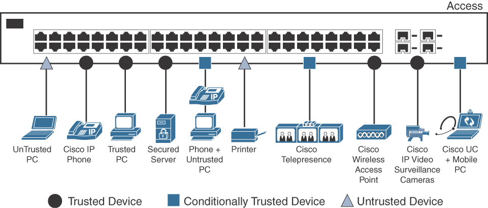
As seen in Figure 12-4, various entities connect to the access layer switch, with the following categories of devices:
![]() Trusted devices: Devices such as Cisco Unified IP Phones, Cisco Wireless Access Points, and Cisco IP Video Surveillance cameras.
Trusted devices: Devices such as Cisco Unified IP Phones, Cisco Wireless Access Points, and Cisco IP Video Surveillance cameras.
![]() Conditionally Trusted Devices: PCs connected (daisy-chained) to IP Phones, PCs running soft clients such as Jabber, and Cisco TelePresence screens.
Conditionally Trusted Devices: PCs connected (daisy-chained) to IP Phones, PCs running soft clients such as Jabber, and Cisco TelePresence screens.
![]() Untrusted Devices: User-owned laptops and network printers.
Untrusted Devices: User-owned laptops and network printers.
Although it’s normal to think of bandwidth as being infinitely available within a LAN, it is important to configure LAN switches to ensure that voice and video traffic receive the required QoS treatment. This further helps marking and classifying traffic closest to the source so that the data center and WAN edge devices trust the marking from the user access layer: Cisco Unified IP Phones, TelePresence endpoints, and so on. It is important to establish a trust boundary to classify and mark traffic as close to its source as possible. This is where a trust boundary must be defined.
QoS Trust Boundary
When deploying QoS, a trust boundary must be defined so that the QoS marking(s) can be trusted from the devices connected at that boundary. The definition of a trust boundary depends on what types of devices are connected at the access layer in a LAN and their trust level (as defined in previous section).
The trust boundary is critical when trusting or untrusting traffic flows. An optimal trust boundary is closer to the source of data. Figure 12-5 illustrates the concept of establishing a viable trust boundary in a typical Cisco Core, Distribution, and Access network.
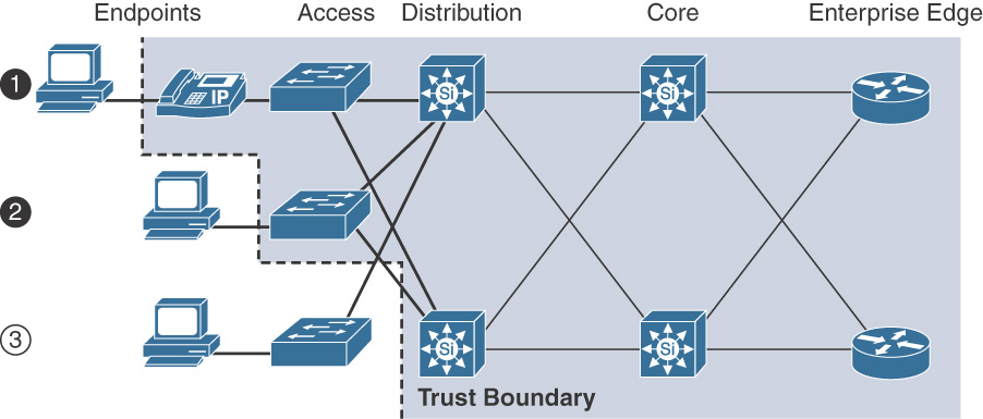
As seen in Figure 12-4, 1 and 2 are optimal trust boundaries, because these are closest to the source. On the other hand, 3 is a suboptimal choice to trust incoming flow from a device.
Because Cisco Unified IP Phones can exchange CDP messages with the Cisco switch, the switch can extend trust to the IP phones and trust traffic received from the IP phones. The Cisco IP phones can re-mark any traffic received from a connected PC on the PC port to class of service (CoS) 0. This process is illustrated in the following steps:
Note
CoS or Layer 2 QoS marking is described in the next section.
Step 1. The switch and Cisco Unified IP Phone exchange CDP messages.
Step 2. The switch extends the trust boundary to the IP phone.
Step 3. The IP phone sets CoS to 5 for phone-sourced media traffic and to 3 for phone-sourced signaling traffic. Additionally, the IP phone sets CoS to 0 for traffic from the PC port.
Step 4. The switch trusts CoS values from the IP phone (if the switch port is configured to trust the connected IP phone) and maps CoS to DSCP for output queuing. The result is CoS 5 = DSCP EF and CoS 3 = DSCP AF31/CS3.
The command to configure trust boundary and CoS/DSCP values up to or beyond an IP Phone is mls qos trust. The possible QoS trust policies for ports connected to conditionally trusted Cisco Unified IP Phones are listed in Table 12-2.
Table 12-2 Switch CoS Trust Policies
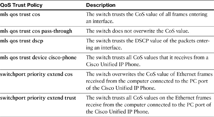
Figure 12-6 gives an overview of trusted, conditionally trusted, and untrusted configurations.
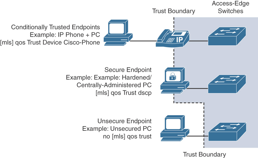
Based on the defined trust boundary and configuration on the device/switch, traffic (packets/frames) can be identified based on classification criteria and can be marked according to a policy so that other network devices and applications will recognize these packets/frames and treat them as per the QoS policy being applied.
Note
Traffic can be marked using fields within packets and frames at Layer 3 and Layer 2 respectively.
At Layer 3, the type of service (ToS) or Differentiated Services (DS) fields in an IP header can be used for marking. At Layer 2, the 802.1p (user priority field) in the IEEE 802.1Q tag can be used for marking traffic. Subsequent sections explain the CoS and ToS markings. The next sections explain the concept of Layer 2 or CoS and Layer 3 or ToS (IP precedence/DSCP) markings.
Layer 2 Marking (CoS)
Class of service (CoS) markings are applied to frames (Layer 2 or data link layer) that transit an 802.1Q trunk. An IEEE 802.1Q tag consists of Tag Protocol ID (TPID) and Tag Control Information (TCI) fields. Figure 12-7 depicts the Layer 2 frame with IEEE 802.1Q tag.
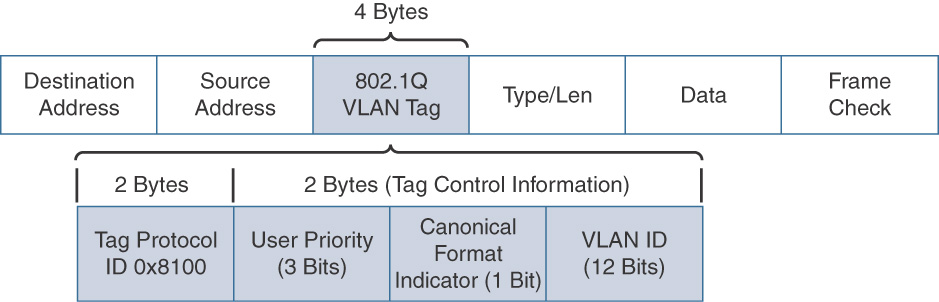
The TPID field is a 2-byte field and contains a fixed value of 0 × 8100 that indicates a tagged (802.1Q) frame. The TCI field is a 2-byte field that contains three subfields:
![]() User Priority: A 3-bit field used to reflect the QoS priority of the frame.
User Priority: A 3-bit field used to reflect the QoS priority of the frame.
![]() Canonical Format Indicator (CFI): A 1-bit field that indicates whether the type of information that a frame is carries is in a canonical (Ethernet) or noncanonical (Token Ring) format.
Canonical Format Indicator (CFI): A 1-bit field that indicates whether the type of information that a frame is carries is in a canonical (Ethernet) or noncanonical (Token Ring) format.
![]() VLAN ID: A 12-bit field that indicates the VLAN from which the frame originated. CoS markings leverage the 3 bits from the User Priority field from within the TCI field in a 802.1Q tagged frame. Because CoS markings use 3 bits, CoS values range from 0 through 7, with values 6 and 7 being reserved, as shown in Table 12-3 that summarizes the various CoS values.
VLAN ID: A 12-bit field that indicates the VLAN from which the frame originated. CoS markings leverage the 3 bits from the User Priority field from within the TCI field in a 802.1Q tagged frame. Because CoS markings use 3 bits, CoS values range from 0 through 7, with values 6 and 7 being reserved, as shown in Table 12-3 that summarizes the various CoS values.
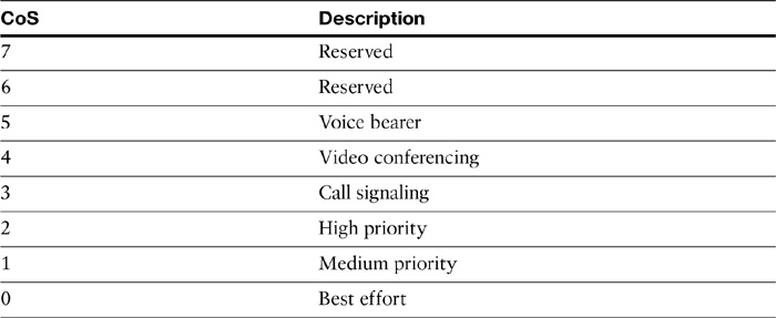
As seen in Table 12-3, the markings use the three 802.1p priority bits and allow a Layer 2 Ethernet trunk frame to be marked with eight different levels of priority, values 0 to 7. The three bits allow for eight levels of classification, permitting a direct correspondence with IPv4 IP precedence ToS values as discussed in next section.
Layer 3 Marking (ToS)
At Layer 3 (network layer), packet marking can be accomplished using the ToS byte in an IPv4 header. Two predominant types of marking mechanisms leverage the ToS byte: IP Precedence and Differentiated Services Code Point (DSCP).
IP Precedence uses the three precedence bits in the IPv4 header’s ToS (type of service) field to specify class of service for each IP packet (IETF RFC 1122). The most significant three bits on the IPv4 ToS field provide up to eight distinct classes, of which six are used for classifying services and the remaining two are reserved. On the edge of the network, IP Precedence is assigned by the client device or the router, so that each subsequent network element can provide services based on the determined policy or the SLA.
Note
IP Precedence is an old approach and has been successively replaced by DSCP for marking IP packets.
IP Precedence uses the 3 leftmost bits in the ToS byte. With 3 bits to use, IP Precedence values can range from 0 to 7, with 6 and 7 reserved. The fields in the ToS byte are as follows:
![]() (IP) Precedence: A 3-bit field used to specify the relative priority or importance of a packet.
(IP) Precedence: A 3-bit field used to specify the relative priority or importance of a packet.
![]() Type of Service (ToS): A 4-bit field that defines how the network should make trade-offs between throughput, delay, reliability, and cost.
Type of Service (ToS): A 4-bit field that defines how the network should make trade-offs between throughput, delay, reliability, and cost.
![]() MBZ: Must be zero.
MBZ: Must be zero.
Figure 12-8 shows the ToS byte structure.
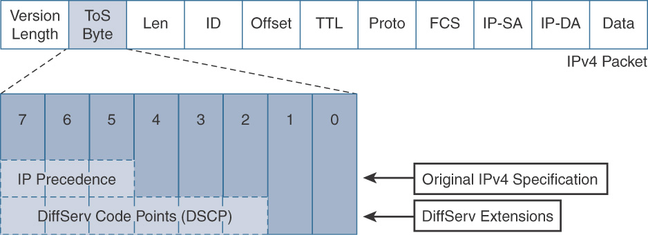
Figure 12-9 gives an insight into the IP Precedence bits (0–2), ToS bits (3–6), and MBZ bit.
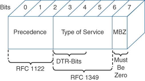
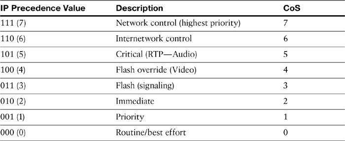
Table 12-4 summarizes the various IP Precedence values.
Table 12-4 IP Precedence Values (and Mapping to CoS)
DSCP uses the six bits in the IPv4 header to specify class of service for each IP packet (IETF RFC 2474). The 6 leftmost bits from the ToS byte in an IPv4 header form the DiffServ (DS) field. With 6 bits, DSCP has up to 64 DSCP values (0 to 63) that are assigned to various classes of traffic. The Internet Engineering Task Force (IETF) recommends selective DSCP values to maintain relative levels of priority. These selective values are called per-hop behaviors (PHB) and determine how packets are treated at each hop along the path from the source to the destination. On the network edge, the IP DSCP is assigned by the client device or the router, so that each subsequent network element can provide services based on the determined policy or the SLA.
The subfields in the DS byte are as follows:
![]() DSCP: A 6-bit field used to specify the DSCP value (and therefore PHB) of a packet.
DSCP: A 6-bit field used to specify the DSCP value (and therefore PHB) of a packet.
![]() CU: Currently unused.
CU: Currently unused.
Figure 12-10 gives an overview of DSCP bits and CU bits.
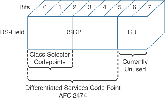
Figure 12-11 illustrates the relationship between the ToS byte, IP Precedence, and DSCP fields.
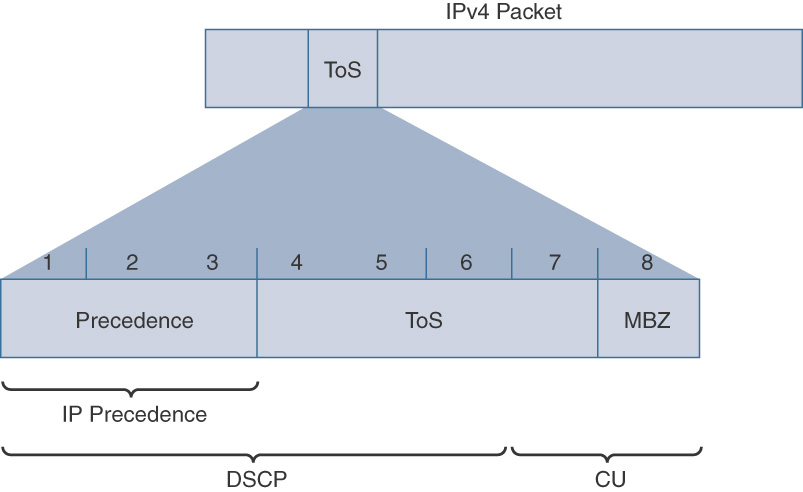
Table 12-5 shows the relationship between DSCP and IP Precedence values.
Table 12-5 DSCP to IP Precedence Value Relationship
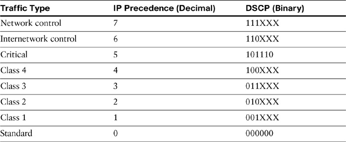
Note
The Class Selector code points are of the form “xxx000.” The first three bits are the IP Precedence bits. Each IP Precedence value can be mapped into a DiffServ class. CS0 (Default) equals IP Precedence 0, CS1 IP Precedence 1, and so on. In case a packet is received from a non-DiffServ-aware router that understands IP precedence markings, the DiffServ router can still understand the encoding as a Class Selector code point.
When configuring a router to mark or recognize a DSCP value, decimal numbers or the name of a specific DSCP value can be used. The four different DiffServ PHBs are as follows:
![]() Assured forwarding (AF): Specifies four AF PHBs grouped into four classes. When using AF, the first 3 bits of the DS field define the queuing class (1 to 4), and next 2 bits define the drop probability (1 to 3). The 6th bit is always zero. AF therefore has 12 classes to it and provides assurance of a packet as long as it doesn’t exceed the subscribed rate.
Assured forwarding (AF): Specifies four AF PHBs grouped into four classes. When using AF, the first 3 bits of the DS field define the queuing class (1 to 4), and next 2 bits define the drop probability (1 to 3). The 6th bit is always zero. AF therefore has 12 classes to it and provides assurance of a packet as long as it doesn’t exceed the subscribed rate.
![]() Best effort (BE): Specified when all 6 bits of the DS field are 0; that is, the packet doesn’t need any specific QoS treatment or doesn’t meet the requirements of any of the other defined classes. BE is also known as default PHB.
Best effort (BE): Specified when all 6 bits of the DS field are 0; that is, the packet doesn’t need any specific QoS treatment or doesn’t meet the requirements of any of the other defined classes. BE is also known as default PHB.
![]() Class Selector (CS): Used for backward compatibility with network devices and applications that use IP Precedence. When using this PHB, the last 3 bits of the DSCP field are 0.
Class Selector (CS): Used for backward compatibility with network devices and applications that use IP Precedence. When using this PHB, the last 3 bits of the DSCP field are 0.
![]() Expedited forwarding (EF): States a low-delay, low-loss, and low-jitter QoS treatment with guaranteed bandwidth.
Expedited forwarding (EF): States a low-delay, low-loss, and low-jitter QoS treatment with guaranteed bandwidth.
Cisco recommends applying classification/marking applicable to all types of traffic, including voice and video media, call signaling traffic, and different data traffic flows. This set of recommendations is called the Cisco QoS baseline. Table 12-6 gives an insight into these service classes.
Table 12-6 Service Classes Based on Cisco QoS Baseline for Voice, Video, and Data
Leading Practices for Classification and Marking for Video Traffic
In addition to the previously discussed QoS requirements for video traffic, the following are best practices associated with interactive video:
![]() Interactive video traffic should be marked to DSCP AF41.
Interactive video traffic should be marked to DSCP AF41.
![]() Excess videoconferencing traffic can be marked down (policing) to AF42 or AF43.
Excess videoconferencing traffic can be marked down (policing) to AF42 or AF43.
![]() Streaming video should be marked to DSCP CS4 (for both unicast and multicast streams).
Streaming video should be marked to DSCP CS4 (for both unicast and multicast streams).
![]() Non-business-oriented streaming video applications, such as entertainment video content, may be marked as Scavenger class DSCP CS1.
Non-business-oriented streaming video applications, such as entertainment video content, may be marked as Scavenger class DSCP CS1.
Queuing
Beginning with classification and marking, a packet needs to be treated according to the QoS policy. QoS tools such as policing or queuing can make forwarding or dropping decisions based on these markings. Queuing is a congestion management tool. It ensures that during temporary periods of congestion traffic (packets) is buffered, prioritized, and, if required, reordered before being transmitted to the destination.
A number of queuing tools are available in Cisco IOS and are listed in Table 12-7.
Table 12-7 Cisco Queuing Toolset
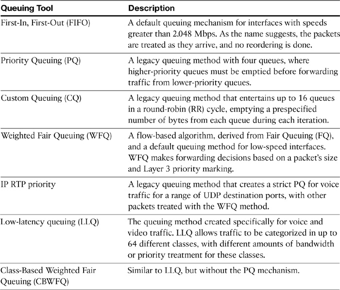
Figure 12-12 shows LLQ and other Class-Based Weighted Fair Queues implemented on Cisco IOS router.
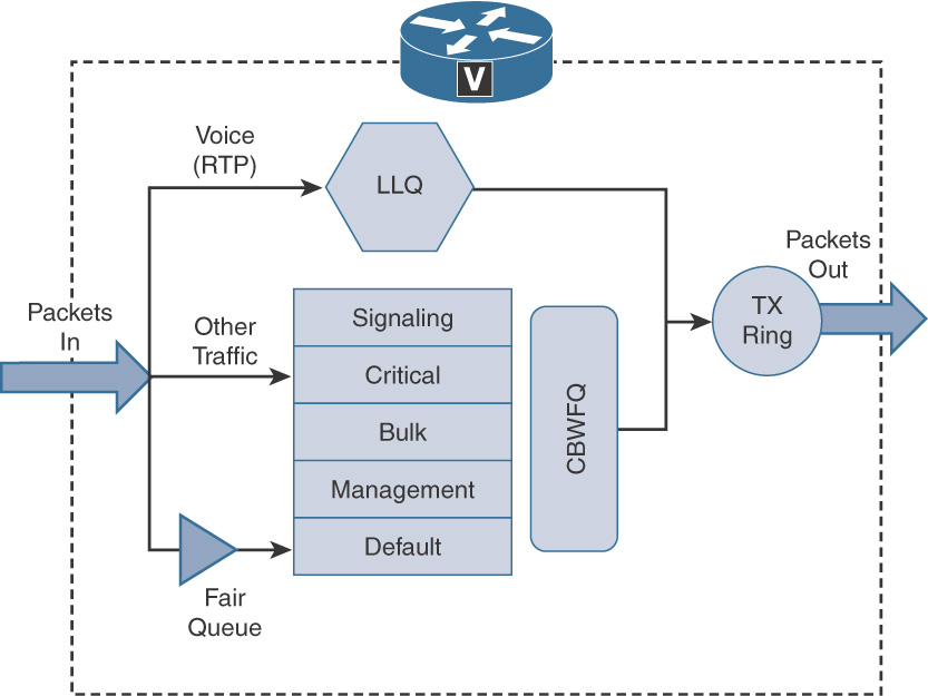
Cisco recommends CBWFQ or LLQ methodologies for queuing with current versions of Cisco IOS in Cisco Collaboration networks. Example 12-1 illustrates the Modular Quality of Service (MQC) approach to LLQ.
Example 12-1 MQC Approach to LLQ
Router(config)# class-map match-any RTP-Audio
Router(config-cmap)# match ip dscp ef
Router(config-cmap)# match ip precedence 5
!
Router(config)# class-map match-any RTP-Video
Router(config-cmap)# match ip dscp cs4
Router(config-cmap)# match ip dscp af41
Router(config-cmap)# match ip precedence 4
!
Router(config)# class-map match-any Signaling
Router(config-cmap)# match ip dscp cs3
Router(config-cmap)# match ip dscp af31
!
Router(config)# policy-map Voice-Priority
Router(config-pmap)# class RTP-Audio
Router(config-pmap-c)# priority percent 20
Router(config-pmap-c)# class RTP-Video
Router(config-pmap-c)# priority percent 10
Router(config-pmap-c)# class Signaling
Router(config-pmap-c)# bandwidth 128
Router(config-pmap-c)# class class-default
Router(config-pmap-c)# fair-queue
!
Router(config)# interface serial 0/0
Router(config-if)# ip address 10.10.1.250 255.255.255.0
Router(config-if)# service-policy output Voice-Priority
Table 12-8 describes the commands used in Example 12-1.
Table 12-8 MQC Commands
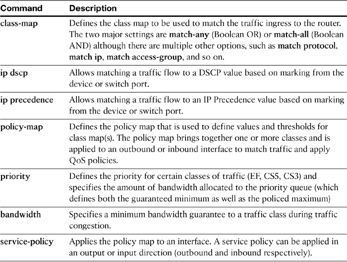
In Example 12-1, match-any commands are used to match RTP audio (DSCP EF and IP Precedence 5) and video (DSCP CS4 and IP Precedence 4) traffic. Signaling traffic is matched by matching DSCP values AF31 and CS3. Voice audio is given priority treatment (guaranteed 20 percent of the link’s bandwidth), whereas video traffic is given 10 percent of the link bandwidth as priority guaranteed bandwidth. Signaling traffic is given up to 128 kbps of guaranteed bandwidth, and the remaining traffic is treated by class default via fair queuing method (that is, this traffic is entertained only when the priority queues have first been serviced up to their assigned bandwidth).
The next section discusses traffic policing and shaping mechanisms.
Traffic Policing and Shaping
Traffic policing and shaping help regulate bandwidth usage by limiting the amount of traffic. Policing limits traffic rates by dropping, remarking, or transmitting traffic if the traffic conforms to a policy. Policing can occur within a network or at the network edge (towards the WAN).
Shaping, on the other hand, involves regulating excessive traffic rates by delaying (buffering) traffic. Shaping usually occurs at the edge of a network and can be applied to an interface in an output direction. Because traffic policing limits traffic transmission by dropping packets, it is more suitable for high-speed links such as LAN or Multiprotocol Label Switching (MPLS) links. Traffic shaping is more suitable for lower-speed links such as Multilink PPP (MLP) and Frame Relay, as it buffers excess traffic.
Both policing and shaping configurations can specify a committed information rate (CIR), committed burst (Bc), and excess burst (Be). Both shaping and policing rely on token-bucket algorithms in which tokens influence how much traffic can be sent, with each token allowing either 1 bit or 1 byte to be sent. There are three types of class-based policers that can be configured using the MQC:
![]() Single-rate two-color policer: A single token bucket is used, and traffic either conforms to or exceeds the configured rate. Actions can be stated for traffic that conforms or exceeds the specified rate.
Single-rate two-color policer: A single token bucket is used, and traffic either conforms to or exceeds the configured rate. Actions can be stated for traffic that conforms or exceeds the specified rate.
![]() Single-rate three-color policer: Two token buckets are used, with tokens periodically added to the first bucket, and any overflowing tokens going to the second bucket as shown in Figure 12-13. Actions can be stated for traffic that conforms, exceeds, or violates the specified rate.
Single-rate three-color policer: Two token buckets are used, with tokens periodically added to the first bucket, and any overflowing tokens going to the second bucket as shown in Figure 12-13. Actions can be stated for traffic that conforms, exceeds, or violates the specified rate.
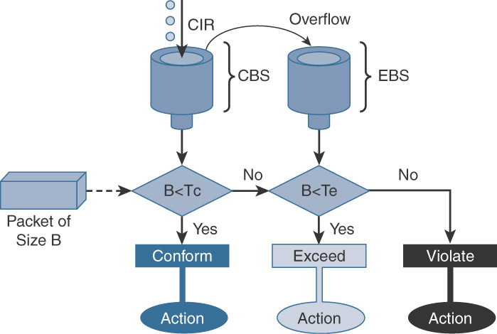
Note
CBS is Committed Burst Size, EBS is Excess Burst Size, Tc is Token Count for CBS, and Te is Token Count for EBS.
![]() Two-rate three-color policer (RFC 2698): Comparable to the single-rate three-color policer, the difference is that tokens are periodically added to both buckets, as shown in Figure 12-14. Actions can be stated for traffic that conforms, exceeds, or violates the specified rate.
Two-rate three-color policer (RFC 2698): Comparable to the single-rate three-color policer, the difference is that tokens are periodically added to both buckets, as shown in Figure 12-14. Actions can be stated for traffic that conforms, exceeds, or violates the specified rate.
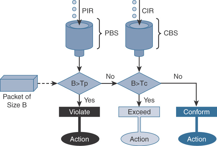
Note
PIR is Peak Information Rate, CBS is Committed Burst Size, PBS is Peak Burst Size, Tp is Token count for PBS, and Tc is Token Count for CBS.
Example 12-2 illustrates a single-rate three-color policer using the MQC in which the traffic conforming to the policy is marked DSCP AF21. The traffic exceeding the policy-defined rate is marked DSCP AF11, and the traffic violating the exceed action is dropped.
Example 12-2 Traffic Policer Configuration
Router(config)# class-map HTTP-Secure
Router(config-cmap)# match protocol secure-http
!
Router(config)# policy-map HTTPS
Router(config-pmap)# class HTTP-Secure
Router(config-pmap-c)# police cir 512000 bc 64000 be 64000 conform-action set-dscp-transmit af21 exceed-action set-dscp-transmit af11 violate-action drop
!
Router(config)# interface FastEthernet 0/0
Router(config-if)# service-policy output HTTPS
Traffic shaping uses a token-bucket system to determine whether to transmit, delay, or drop new packets. The following entities form the basis of traffic shaping (CIR, Bc, Tc):
![]() With the token-bucket system, each interface has a committed information rate (CIR), which is the rate at which the interface can transmit packets for an interval of time, or in token-bucket theory, the rate at which the tokens are added to the bucket.
With the token-bucket system, each interface has a committed information rate (CIR), which is the rate at which the interface can transmit packets for an interval of time, or in token-bucket theory, the rate at which the tokens are added to the bucket.
![]() The sustained burst rate (Bc) defines the maximum number of tokens that the bucket can contain at a given interval. When a packet arrives at an interface, it takes a token from the bucket.
The sustained burst rate (Bc) defines the maximum number of tokens that the bucket can contain at a given interval. When a packet arrives at an interface, it takes a token from the bucket.
![]() When a packet is transmitted, the token is released, and after the time interval (Tc), the token is returned to the bucket. If the bucket is empty, any new packets arriving at that interface are queued until the time interval has elapsed and the tokens have been replenished.
When a packet is transmitted, the token is released, and after the time interval (Tc), the token is returned to the bucket. If the bucket is empty, any new packets arriving at that interface are queued until the time interval has elapsed and the tokens have been replenished.
Note
Traffic shaping buffers the traffic to a certain bitrate, and then policing drops the traffic when it exceeds a certain bitrate.
Traffic shaping can be applied to a number of different Layer 2 technologies, such as Ethernet, ATM, High-Level Data Link Control (HDLC), PPP (ISDN and dialup interfaces are not supported), and Frame Relay.
Note
With the exception of Frame Relay, all of these technologies support Generic Traffic Shaping (GTS).
Traffic shaping is recommended by Cisco under the following conditions:
![]() There is a mismatch between link speeds at a central site and remote sites (that is, the central site link speed is greater than that of the remote sites).
There is a mismatch between link speeds at a central site and remote sites (that is, the central site link speed is greater than that of the remote sites).
![]() The aggregate link speed at remote sites is greater than that at the central site.
The aggregate link speed at remote sites is greater than that at the central site.
Example 12-3 illustrates GTS-based traffic shaping.
Example 12-3 GTS-Based Traffic Shaping
Router(config)# interface Serial0/1
Router(config-if)# ip address 10.10.10.51 255.255.255.0
Router(config-if)# traffic-shape rate 256000 32000 32000 1000
!
Router# show traffic-shape
Interface Se0/1
Access Target Byte Sustain Excess Interval Increment Adapt
VC List Rate Limit bits/int bits/int (ms) (bytes) Active
- 256000 8000 32000 32000 125 4000 -
In Example 12-3, traffic shaping is used to limit the rate on all traffic on interface serial0/1 to 256 kbps. This limit is imposed by delaying any traffic over 32 kb/interval; the interval of time used to shape traffic is 125 ms. So, in this case, during each 125-ms interval, interface serial0/1 can transmit up to 32 kb. Any amount of traffic that exceeds the 32 kb limit during that interval is queued until the next interval.
Traffic shaping can also leverage the MQC framework, and when configuring MQC-based shaping, traffic can be shaped to either average or peak. If shape average is specified, traffic is sent at the CIR, with bursting of Be bits per timing interval enabled. If shape peak is specified, traffic is forwarded at the peak rate.
Example 12-4 shows the configuration of class-based Frame Relay traffic shaping for HTTPS traffic at least 256 kbps but no more than 512 kbps.
Example 12-4 Frame Relay Traffic Shaping
Router(config)# class-map HTTP-Secure
Router(config-cmap)# match protocol secure-http
!
Router(config)# policy-map HTTPS
Router(config-pmap)# class HTTP-Secure
Router(config-pmap-c)# shape average 512000
Router(config-pmap-c)# bandwidth 256
!
Router(config)# map-class frame-relay FRFMAP
Router(config-map-class)# service-policy output HTTPS
Router(config-map-class)# frame-relay fragment 640
!
Router(config)# interface serial 0/0
Router(config-if)# frame-relay traffic-shaping
!
Router(config-if)# interface serial 0/0.1 point-to-point
Router(config-subif)# ip address 10.10.1.250 255.255.255.0
Router(config-subif)# frame-relay interface-dlci 100
Router(config-fr-dlci)# class FRFMAP
Medianet
To facilitate anywhere, anytime immersive or pervasive video, the underlying network needs to be tuned accordingly. Since video traffic is bursty and unpredictable, fine-tuning an existing network infrastructure for video traffic can be challenging.
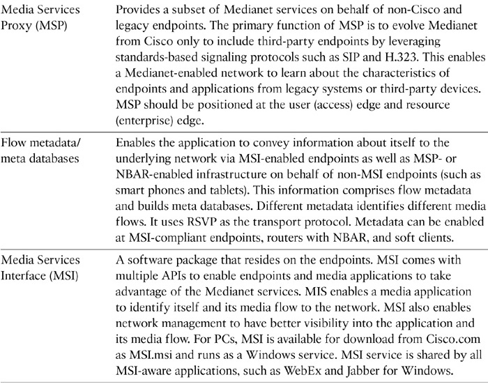
Medianet is the architecture for successful deployment of multiple media and collaboration applications with special focus on video. It requires Media Services Interface (MSI)–equipped products and features in both smart endpoints/applications and smart network infrastructure, as shown in Figure 12-15. However, Medianet does not require an entirely end-to-end network with Medianet enabled in every hop.
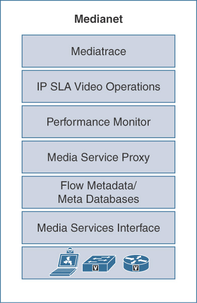
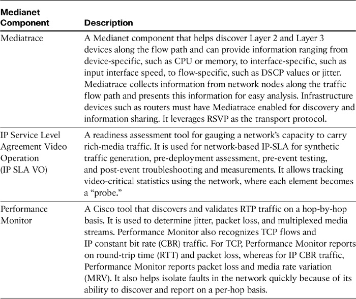
Medianet components are explained in Table 12-9.
Table 12-9 Cisco Medianet Components
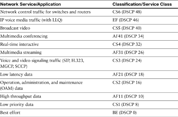
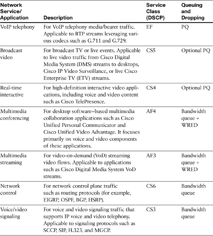
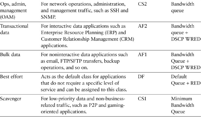
Medianet QoS Classes of Service
Multiple endpoints and applications can leverage Medianet. However, each group of devices, endpoints, and media applications has unique traffic patterns and service level requirements that necessitate a dedicated QoS class to meet that service level. RFC 4594 presents configuration guidelines for DiffServ service classes to meet specific business requirements. Table 12-10 describes the various network applications and respective QoS (DiffServ) service classes.
Voice and Video Bandwidth Calculations
This section describes the bandwidth calculations for voice and video traffic, as well as Layer 2 overhead considerations.
Bandwidth Calculations for Voice Calls
This section gives insight to calculation of bandwidth for voice (audio) calls.
To calculate bandwidth requirements for voice traffic, you must have the following information:
![]() choice of codec
choice of codec
![]() packetization interval
packetization interval
A key factor to consider is that payload size is comparable to header size. The more packets you have and the shorter the packetization time, the more overhead you will have.
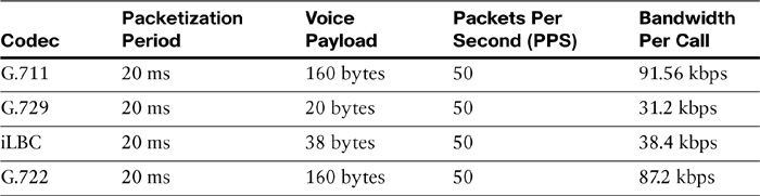
In Table 12-11, the bandwidth requirements per codec are shown. The bandwidth shown in the table as is required per call does not take into account Layer 2 overhead.
Note
If Layer 2 overhead is taken into account, total overhead is even higher. In addition, this formula does not consider the effect of any link-efficiency tools.
The formula to calculate the bandwidth per call is:
Bandwidth per call = (Voice Payload + L3 OH + L2 OH) X PPS X 8bits/byte
Where, L3 = Layer 3, L2 = Layer 2, OH = Overhead, PPS = Packets Per Second
Bandwidth Calculations for Video Calls
This section describes how to perform bandwidth calculations for video traffic when implementing QoS in the network.
Deciding bandwidth requirements for voice traffic is relatively straightforward. Once you specify the codec, the required bandwidth and the quality of that compressed signal are automatically defined. The quality of the compressed signal is the width of the frequency spectrum of the encoded voice signal.
Calculations are different for video codecs. Resolution and frame rate calculations are based on endpoint capabilities, and at times, user selection criteria are based on the desired call quality. In addition, video conferencing traffic utilizes optimum definition profiles. There are three categories of optimum definition profiles:
![]() High
High
![]() Medium
Medium
![]() Normal
Normal
The profiles are defined based on the quality of the image gathered by the camera and the quality of lighting available. The profiles set bandwidth utilization, with the best lighting and camera requiring less bandwidth for the image. Out of the three profiles, High is typically utilized for dedicated videoconference rooms, with excellent lighting and a high quality camera, and saves up 50% of the bandwidth compared to Normal. Medium is used for stable, well-lit areas with decent quality cameras and saves approximately 25% of the bandwidth compared to Normal, which is used for poorly lit environments.
Optimal resolution profiles provide a good demonstration of how much the system can compress video input. With perfect lighting conditions and predefined bandwidth, higher resolution and higher frame rates are possible. Table 12-12 shows that with perfect lighting conditions, it is possible to achieve resolution of 720 lines and 60 frames with 1152 kbps of bandwidth. If the input signal is not as good—perhaps the lighting conditions are not ideal—the codec lowers either the frame rate (from 60 fps to 30 fps) or the resolution (from 720 lines to 576) to fit the video into same bandwidth pipe.
Table 12-12 Video Profile Bandwidth
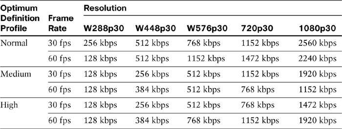
When encoding and transmitting video, there is a trade-off between high resolution and a high frame rate. Sports events, like a basketball game or a car race, look better with a higher frame rate, while a business meeting is better at a higher resolution over motion.
Bandwidth Calculations for Layer 2 Overhead
This section describes Layer 2 overhead details that are related to bandwidth calculations.
Most typical Layer 2 technologies and their associated overhead are described in the following list. Consider these overheads when calculating bandwidth requirements for a single VoIP call.
![]() 802.3 Ethernet: 14+4 bytes
802.3 Ethernet: 14+4 bytes
![]() 802.1Q Ethernet: 4 additional bytes
802.1Q Ethernet: 4 additional bytes
![]() Frame Relay: 6 bytes (9 bytes with LFI (link fragmentation and interleaving))
Frame Relay: 6 bytes (9 bytes with LFI (link fragmentation and interleaving))
![]() PPP: 6-9 bytes
PPP: 6-9 bytes
Note
Data-link transport protocols use various preambles, frame headers, flags, cyclic redundancy check (CRC), Asynchronous Transfer Mode (ATM) cell padding, and other things that influence bandwidth calculations. Therefore, the header can vary.
In Table 12-13, the Layer 2 overhead requirements per codec and per PPS amount are shown.
Table 12-13 Layer 2 Overhead Requirements
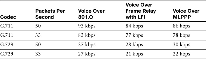
Table 12-13 shows the bandwidth requirements, including Layer 3 and Layer 2 overhead, for the G.711 and G.729 audio codecs at 50 and 33 PPS.
The sample calculation below uses the formula that was previously mentioned. The example shows how to calculate the required bandwidth for a single G.711 call, when the call is transported over Ethernet with 801.Q VLAN framing at 50 packets per second (pps) and 20-ms packetization period:
BW Per Call = (160 + 40 + 32) × 50 × 8 bits/byte = 93 kbps
where:
![]() 160 bytes is the G.711 payload collected over 20 ms.
160 bytes is the G.711 payload collected over 20 ms.
![]() 40 bytes is the Layer 3 + overhead (IP, UDP, RTP headers).
40 bytes is the Layer 3 + overhead (IP, UDP, RTP headers).
![]() 20 bytes is the Layer 2 overhead for 801.Q Ethernet.
20 bytes is the Layer 2 overhead for 801.Q Ethernet.
![]() 50 pps is the sampling rate.
50 pps is the sampling rate.
![]() 8 bits per byte is used to convert byte values into bits for the final bits-per-second result, which is 93 kbps.
8 bits per byte is used to convert byte values into bits for the final bits-per-second result, which is 93 kbps.
Use the same approach when calculating the required bandwidth for other codecs and Layer 2 technologies.
Chapter Summary
The following list summarizes the key points that were discussed in this chapter:
![]() Cisco Collaboration solutions offer multiple applications for both audio and video over a converged network.
Cisco Collaboration solutions offer multiple applications for both audio and video over a converged network.
![]() Converged networks must take into account delay, jitter, and packet loss to provide adequate service and reliability to voice and video traffic.
Converged networks must take into account delay, jitter, and packet loss to provide adequate service and reliability to voice and video traffic.
![]() Cisco offers a QoS toolkit that can be leveraged for implementing end-to-end QoS.
Cisco offers a QoS toolkit that can be leveraged for implementing end-to-end QoS.
![]() Classification and marking is the first step in performing QoS and can be conducted at Layer 2 (CoS) and Layer 3 (ToS).
Classification and marking is the first step in performing QoS and can be conducted at Layer 2 (CoS) and Layer 3 (ToS).
![]() DSCP (with PHB) and IP Precedence are interoperable and are the most commonly used DiffServ methods in Collaboration networks for Layer 3 QoS.
DSCP (with PHB) and IP Precedence are interoperable and are the most commonly used DiffServ methods in Collaboration networks for Layer 3 QoS.
![]() Traffic policing offers various mechanisms to sort, remark, or discard traffic based on defined conditions.
Traffic policing offers various mechanisms to sort, remark, or discard traffic based on defined conditions.
![]() Traffic shaping allows shaping traffic to confirm to an interface’s logical/physical maximum transfer limit, thereby controlling the flow of traffic to remote site.
Traffic shaping allows shaping traffic to confirm to an interface’s logical/physical maximum transfer limit, thereby controlling the flow of traffic to remote site.
![]() Medianet offers a comprehensive suite of applications/components to fine-tune a Cisco Collaboration network for supporting video pertinent QoS for broadcast, streaming, IP telephony, and immersive calls.
Medianet offers a comprehensive suite of applications/components to fine-tune a Cisco Collaboration network for supporting video pertinent QoS for broadcast, streaming, IP telephony, and immersive calls.
![]() Voice and video call bandwidth calculation is influenced by Layer 2, Layer 3, compression and security technologies that impose overhead.
Voice and video call bandwidth calculation is influenced by Layer 2, Layer 3, compression and security technologies that impose overhead.
![]() Video bandwidth calculations are based on resolution profiles, and bandwidth can be largely affected by lighting and camera quality.
Video bandwidth calculations are based on resolution profiles, and bandwidth can be largely affected by lighting and camera quality.
References
For additional information, refer to the following:
Cisco Systems, Inc. Cisco Collaboration Systems 10.x Solution Reference Network Designs (SRND), May 2014.
http://www.cisco.com/c/en/us/td/docs/voice_ip_comm/cucm/srnd/collab10/collab10.html
Cisco QoS DocWiki
http://docwiki.cisco.com/wiki/Quality_of_Service_Networking
Enterprise Media QoS
Review Questions
Use the questions here to review what you learned in this chapter. The correct answers are found in Appendix A, “Answers to the Review Questions.”
1. Which of the following is not a QoS configuration?
a. Compress the data and headers.
b. Drop low-priority packets early.
c. Increase the bandwidth of the link.
d. Incorporate advanced queuing technologies.
e. Reduce link MTU size.
2. Which two features characterize converged network traffic? (Choose two.)
a. No low-speed links
b. Time-sensitive packets
c. Network protocol mix
d. Intolerance of brief outages
e. Bursty small packet flow
3. Which of the following voice codecs utilizes the least amount of bandwidth?
a. G.722
b. G.711
c. G.729
d. iLBC
4. Which statement is the least applicable for the definition of a QoS policy?
a. User-validated
b. Networkwide
c. Time-based
d. Ports that are opened on firewalls
e. Different classes of network traffic
5. Which of the following are the most common values for packets per second for voice traffic? (Choose two.)
a. 50 pps
b. 88 pps
d. 33 pps
6. True or false? Layer 2 overhead doubles the bandwidth required for a voice packet.
a. True
b. False
7. Which of the following profiles utilizes the most bandwidth?
a. High
b. Normal
c. Medium
d. iBLC
8. Medianet is used primarily for which type of traffic in Cisco Collaboration network?
a. Video traffic
b. Signaling traffic
c. Audio traffic
d. WebEx traffic
9. True or false? IP Precedence is a Layer 3 QoS mechanism.
a. True
b. False
10. True or false? SIP Trunks using TCP as protocol from CUCM are insensitive to latency and delay.
a. True
b. False
11. Which element binds a QoS policy to a physical or logical interface on IOS router?
a. Policy map
b. Class map
c. Service policy