10 Opto-electronics and the optical block
As the compact disc player uses a laser beam to read the disc, we will sketch some basic principles of opto-electronics – the technological marriage of the fields of optics and electronics. The principles are remarkably diverse, involving such topics as the nature of optical radiation, the interaction of light with matter, radiometry, photometry, and the characteristics of various sources and sensors.
By convention, electromagnetic radiation is specified according to its wavelength (λ). The frequency of a specific electromagnetic wavelength is given by:
![]()
where f is frequency in Hz, c is the velocity of light (3 × 10⁸ m s–1) and λ is wavelength in m.
The optical portion of the electromagnetic spectrum extends from 10 to 106 nm and is divided into three major categories: ultraviolet (UV), visible and infrared (IR).
UV is those wavelengths falling below the visible spectrum and above X-rays. UV is classified according to its wavelength as extreme or shortwave UV (10–200 nm), far (200–300 nm) and near or long-wave UV (300–370 nm).
Visible is those wavelengths between 370 and 750 nm, which can be perceived by the human eye. Visible light is classified according to the various colours its wavelengths elicit in the mind of a standard observer. The major colour categories are: violet (370–455 nm), blue (456–492 nm), green (493–577 nm), yellow (578–597 nm), orange (598–622 nm) and red (623–750 nm).
IR is those wavelengths above the visible spectrum and below microwaves. IR is classified according to its wavelength as near (750–1500 nm), middle (1600–6000 nm), far (6100–40 000 nm) and far-far (41 000–106 nm).
Interaction of optical waves with matter
An optical wave may interact with matter by being reflected, refracted, absorbed or transmitted. The interaction normally involves two or more of these effects.
Reflection
Some of the optical radiation impinging upon any surface is reflected away from the surface. The amount of reflection varies according to the properties of the surface and the wavelength, and in real circumstances may range from more than 98% to less than 1% (a lampblack body). Reflection from a surface may be diffuse, specular or a mixture of both.
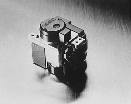
Figure 10.1 Optical block of a compact disc player.
A diffuse reflector has a surface which is rough when compared to the wavelength of the impinging radiation (Figure 10.2).
A specular, sometimes called regular, reflector, on the other hand, has a surface which is smooth when compared to the wavelength of the impinging radiation. A perfect specular reflector will thus reflect an incident beam without altering the divergency of the beam.
A narrow beam of optical radiation impinging upon a specular reflector obeys two rules, illustrated in Figure 10.3.
1 |
The angle of reflection is equal to the angle of incidence. |
2 |
The incident ray and the reflected ray lie in the same plane as a normal line extending perpendicularly from the surface. |
Absorption
Some of the optical radiation impinging upon any substance is absorbed by the substance. The amount of absorption varies according to the properties of the substance and the wavelength, and in real circumstances may range from less than 1% to more than 98%.
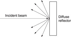
Figure 10.2 Reflection of light from a diffuse reflector.
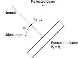
Figure 10.3 Reflection of light from a specular reflector.
Transmission
Some of the optical radiation impinging upon a substance is transmitted into the substance. The penetration depth may be shallow (transmission = 0) or deep (transmission more than 75%).
The reflection (ρ), the absorption (α) and the transmission (σ) are related in the expression:
ρ + α + σ = 1
Refraction
A ray of optical radiation passing from one medium to another is bent at the interface of the two media if the angle of incidence is not 90°.
The index of refraction n is the sine of the angle of incidence divided by the sine of the angle of refraction, as illustrated in Figure 10.4. Refractive index varies with wavelength and ranges from 1.0003 to 2.7.
Optical components are used both to manipulate and control optical radiation, and to provide optical access to various sources and sensors.
Glass is the most common optical material at visible and near-IR wavelengths, but other wavelengths require more exotic materials, such as calcium aluminate glass (for middle IR) and lithium fluoride (for UV).
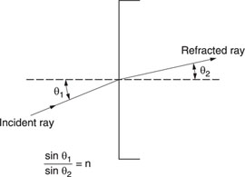
Figure 10.4 The index of refraction.
Figure 10.5 shows how an optical ray passes through a this simple lens.
A lens may be either positive (converging) or negative (diverging). The focal point of a lens is that point at which the image of an infinitely distant point source is reproduced.
Both the source and the focal point lie on the lens axis. The focal length (f) is the distance between the lens and the focal point. The f/number of a lens defines its light-collecting ability and is given by:
![]()
where f is the focal length and D is the diameter of the lens.
A small f/number denotes a large lens diameter for a specified focal length and a higher light-collecting ability than a large f/number.
Numerical aperture (NA) is a measure of the acceptance angle of a lens and is given by:
NA = n sin θ
where n is the refractive index of the objector image medium (for air, n = 1) and θ is half the maximum acceptance angle (shown in Figure 10.6). The relation of the focal length (f) to the distances between the lens and the object being imaged (s) and the lens and the focused image (s′) is given by the Gaussian form of the thin lens equation:
1/s + 1/s′ = l/f
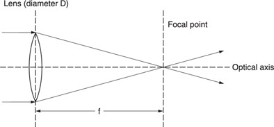
Figure 10.5 How light is refracted through a thin simple lens.
The combined focal length for two thin lenses in contact or close proximity and having the same optical axis is given by:
1/f = 1/f1 + l/f2
The relationship between the focal length (f) and the refractive index (n) is:
l/f = (n – 1)(l/r1 – l/r2)
where r1 is the radius of the left lens surface and r2 is the radius of the right lens surface.
The cylindrical lens
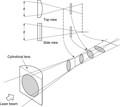
A cylindrical lens is a section of a cylinder and therefore magnifies in only one plane. An optical beam which enters the cylindrical lens shown in Figure 10.7 is focused only in the horizontal plane. As a result the cross-section of the beam after passing through the lens is elliptic, with the degree varying according to the distance from the lens. By detecting the elliptic degree, a useful measure of whether or not a beam is focused on a surface can be made.
The prism
A prism is an optically transparent body used to refract, disperse or reflect an optical beam. The simplest prism is the right-angle prism, shown in Figure 10.8.
An optical ray perpendicularly striking one of the shorter faces of the prism is totally internally reflected at the hypotenuse, undergoes a 90° deviation and emerges from the second shorter face.
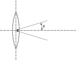
Figure 10.6 Acceptance angle of a lens.
Figure 10.7 Operation of a cylindrical lens.
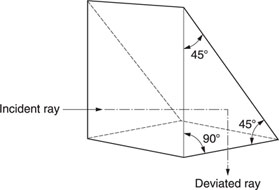
Figure 10.8 Right-angle prism.
Operation of a totally internally reflecting prism is dependent upon the fact that a ray impinging upon the surface of a material having a refractive index (n) smaller than the refractive index (n′) of the medium in which the ray is propagating will be totally internally reflected when the angle of incidence is greater than a certain critical angle (θc) given by:
![]()
The combination of two simple lenses is commonly used to increase the diameter of a beam while reducing its divergence. Such a collimator is shown in Figure 10.9.
Diffraction gratings
Diffraction gratings are used to split optical beams and usually comprise a thin plane parallel plate, one surface of which is coated with a partially reflecting film of thin metal with thin slits. Figure 10.10 shows a diffraction grating used with a prism.
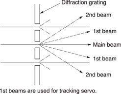
The slits are spaced only a few wavelengths apart. When the beam passes through the grating it diffracts at different angles, and appears as a bright main beam with successively less intensive side beams, as shown in Figure 10.11.
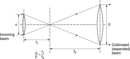
Figure 10.9 Principle of a collimator.
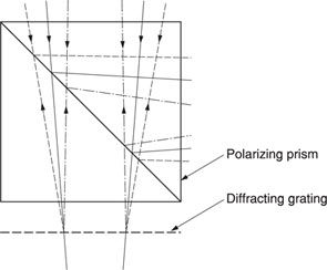
Figure 10.10 A diffraction grating used with a prism (part of a CD player optical pick-up).
Figure 10.11 Light passing through a diffraction grating.
Quarter wave plate
When linear polarized light is passed through an anisotropic crystal (Figure 10.12), the polarization plane will be contorted during the traverse of the crystal. The thickness d of the crystal required to obtain a contortion of more than 180° is equal to one wavelength of the light. In order to obtain a contortion of more than 45°, only one-quarter of d is therefore required, and a crystal with this thickness is used in an optical pick-up in a CD player, and is called a 1/4 wave plate, quarter wave plate or QWP.
The injection laser diode (ILD)
The basic operation of any laser consists of pumping the atoms into a stimulated state, from which electrons can escape and fall to the lower energy state by giving up a photon of the appropriate energy. In a solid-state laser, the input energy populates some of the usually unpopulated bands. When a photon of energy equal to the band gap of the crystal passes through, it stimulates other excited photons to fall in step with it. Thus, a small priming signal will emerge with other coherent photons.
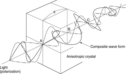
Figure 10.12 Light passing through an anisotropic crystal becomes rotated in polarization.
The laser can be operated in a continuous wave (CW) oscillator mode if the ends of the laser path are optically flat, parallel and reflective, so forming an optical resonant cavity. A spontaneously produced photon will rattle back and forth between the ends, acquiring companions due to stimulated emission.
This stimulated emission can be like an avalanche, completely draining the high-energy states in a rapid burst of energy. On the other hand, certain types of lasers can be produced which will operate in an equilibrium condition, giving up photons at just the input energy pumping rate. The injection laser diode (ILD) is such a device.
The material in an injection laser diode is heavily doped so that, under forward bias, the region near the junction has a very high concentration of holes and electrons. This produces the inversion condition with a large population of electrons in a high-energy band and a large population of holes in the low-energy band. In this state, the stimulated emission of photons can overcome photon absorption and a net light flux will result.
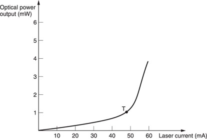
In operation, the forward current must reach some threshold, beyond which the laser operates with a single ‘thread’ of light, and the output is relatively stable but low. As the current is increased, light output increases rapidly.
The ILD characteristic is highly temperature-sensitive. A small current variation or a modest temperature change can cause the output to rise so rapidly that it destroys the device. A photodiode, monitoring the light output, is commonly used in a feedback loop to overcome this problem.
Like the LED, the ILD must be driven from a current source, rather than a voltage source, to prevent thermal runaway. With a voltage source, as the device junction begins to warm the forward voltage drop decreases, which tends to increase the current, in turn decreasing the forward voltage drop, and so on until the current tends towards infinity and the device is destroyed.
In addition, the ILD has a tendency to deteriorate with operation. Deterioration is greatly accelerated when operating the ILD outside of its optimum limits. A typical ILD characteristic is shown in Figure 10.13.
Figure 10.13 Characteristic of a typical ILD.
The ILD with a double heterostructure (DH)
A very narrow P-N junction layer of GaAs semiconductor is sandwiched between layers of AlGaAs.
The properties of the outer semiconductor layers confine the electrons and holes to the junction layer, leading to an inverted population at a low input current.
Quantum aspects of the laser
A laser (light amplification by stimulated emission of radiation) is a maser (microwave amplification by stimulated emission of radiation) operating at optical frequencies.
Because the operations of masers and lasers are dependent upon quantum processes and interactions, they are known as quantum electronic devices. The laser, for example, is a quantum amplifier for optical frequencies, whereas the maser is a quantum amplifier for microwave frequencies.
Masers and lasers utilize a solid or gaseous active medium, and their operations are dependent on Planck’s law:
ΔE = E2– E1= hf
An atom can make discontinuous jumps or transitions from one allowed energy level (E2) to another (E1), accompanied by either the emission or absorption of a photon of electromagnetic radiation at frequency f.
The energy difference E is commonly expressed in electronvolts (abbreviation: eV) and:
1 eV = 1.6 × 10⁻¹⁹ J
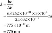
The constant h is Planck’s constant and equals 6.6262 × 10⁻³⁴ J s. The frequency f (in hertz) of the radiation and the associated wavelength λ (in metres) are related by the expression:
![]()
where c (the velocity of light) is 3 × 10⁸ m s–1.
Example:
ΔE = E2 – E1 = 1.6 eV
= 1.6 × 1.6 × 10−19J
= 2.5632 × 10⁻¹⁹J
However, ΔE also equals:
![]()
So:
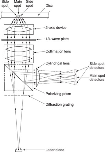
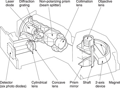
The schematic of an optical pick-up of the three-beam type used in CD players is shown in Figure 10.14. This diagram shows the different optical elements composing a pick-up and indicates the laser beam route through the unit.
The laser beam is generated by the laser diode. It passes through the diffraction grating, generating two secondary beams called side beams, which are used by a tracking servo circuit to maintain correct tracking of the disc.
The beam enters a polarizing prism (called a beam splitter) and only the vertical polarized light passes. The light beam, still divergent at this stage, is converged into a parallel beam by the collimation lens and passed through the 1/4 wave plate, where the beam’s polarization plane is contorted by 45°. The laser beam is then focused by a simple lens onto the pit surface of the disc. The simple lens is part of a servo-controlled mechanism known as a two-axis device.
Figure 10.14 A three-beam optical pick-up.
The beam is reflected by the disc mirrored surface, converged by the two-axis device lens into a parallel beam, and re-applied to the 1/4 wave plate. Again, the polarization plane of the light is contorted by 45°, so the total amount of contortion becomes 90°, i.e., the vertically polarized laser beam has been twisted to become horizontally polarized.
After passing through the collimation lens, the laser beam is converged onto the slating surface of the polarizing prism. Now polarized horizontally, the beam is reflected internally by the slanted surface of the prism towards the detector part of the pick-up device.
In the detector part, the cylindrical lens focuses the laser beam in only one plane, onto six photo-detectors in a format shown in Figure 10.15, i.e., four main spot detectors (A, B, C and D) and two side spot detectors (E and F), enabling read-out of the pit information from the disc.
The T-type optical pick-up (TOP) is shown in detail in Figure 10.16.
FOP: flat-type optical pick-up
Later models use a flat-type optical pick-up (FOP), shown in Figure 10.17. In the FOP, a non-polarizing prism is used and no 1/4 wave plate. The non-polarizing prism is a half mirror which reflects half of the incident light and lets pass the other half (Figure 10.18).
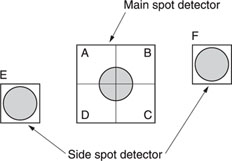
Figure 10.15 Relative positions of the six photodetectors of a CD optical pick-up.
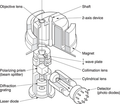
Figure 10.16 T-type optical pick-up (TOP).
Figure 10.17 Flat-type optical pick-up (FOP).
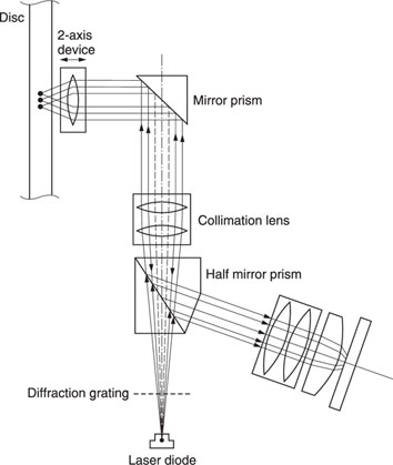
Figure 10.18 Beam splitting in the FOP.
This means that half of the light passes through the prism and returns after being reflected by the mirror. This secondary beam, 50% of the original, is reflected again for 50% and passed through for 50%, so that the resulting light beam intensity is 1/2 × 1/2 = 1/4 of the original beam (Figure 10.19).
The new principle enables the elimination of the influence of double refraction (i.e. the change of the deflection angle when reflected by the disc surface), caused by discs with mirror impurities.
Two-axis device
Optical pick-ups contain an actuator for objective lens position control. The compact disc player, due to the absence of any physical contact between the disc and the pick-up device, has to contain auto-focus and auto-tracking functions.
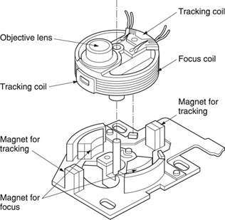
These functions are performed by the focus and tracking servo circuits via the two-axis device, enabling a movement of the objective lens in two axes: vertically for focus correction and horizontally for track following. Figure 10.20 shows such a two-axis device construction.
The principle of operation is that of the moving coil in a magnetic field. Two coils, the focus coil and the tracking coil, are suspended between magnets (Figure 10.21), creating two magnetic fields. A current through either coil, due to the magnetic field, will cause the coil to be subjected to a force, moving the coil in the corresponding direction.
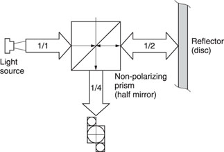
Figure 10.19 Light distribution in the FOP.
Figure 10.20 Construction of a two-axis device, used to focus the laser beam onto the surface of a compact disc.
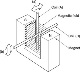
Figure 10.21 Operating principle of a two-axis device.

