
Installing AM HD Radio and Making it Work
5
5.1 Getting started with AM HD Radio
While, in a general sense, installing the HD Radio equipment at the AM transmitter is a fairly simple process, there are requirements that the transmitter and antenna system must meet. There are hardware options that you should strongly consider. A spectrum analyzer is required, and it must be set up in a specific manner to correctly adjust the HD Radio transmission system. This chapter will discuss all of this and help you get your HD Radio signal on the air by providing a complete description of the process.
Most of my experience is with an original iBiquity Digital Corporation exciter and with the Harris DexStarTM exciter. Many of my setup references in this chapter will be references from the DexStar. Read through this chapter, and compare the DexStar references to the manual on your exciter. Many descriptions are the same; some will be slightly different, as the manufacturers have the flexibility to manipulate the graphical user interface (GUI) of the system.
In addition to the HD Radio transmission equipment, you will need the proper licensing agreement from iBiquity Digital Corporation to operate your main HD Radio channel. The license for the main HD Radio channel is a one-time payment. Contrary to what you may have heard, there is no “perpetual” fee to operate your main HD Radio channel. If you intend to operate multicast channels (if that option becomes available for AM HD Radio) or sell utilization of your available data channels, iBiquity Digital Corporation does have a quarterly payment schedule for these additional services. Please consult with iBiquity Digital Corporation for specifics.
5.2 Internet access and IP ability
While not completely vital to the operation of the exciter at this point in time, you should consider having Internet access installed at the transmitter facility. Whether it is a dedicated DSL, or you bring it in via microwave or through the T1 you are using to bring audio to the site, is irrelevant. Having the largest “pipe” available coming into the site is not relevant, either. It is important that the Internet access is always on.
Later on, as we’re setting up the exciter and getting the HD Radio signal on the station, you will see where Internet access comes into play. Briefly, having Internet access at the site will allow you to get into the exciter remotely to assess a possible situation. I have been able to get into an exciter, spot an error in the process of starting, and reboot the exciter before it had a chance to crash and take the station off the air.
You will also probably wish to run various data, for example, PAD (such as song title and artist) to your exciter. This can be done in many ways, but an IP connection is the easiest. And because your audio processing will be at the transmitter, being able to get into the processor from outside the transmitter facility via IP would be a great aid in fine-tuning the processing.
5.2.1 IP connectivity
IP connectivity to the transmitter site is important from two aspects. First, it will allow you to control the exciter from another location, such as your desk. Second, it is the preferred way to get PAD into the exciter.
IP connectivity can be through the Internet, over your bidirectional STL, through the use of a spread-spectrum IP radio, or through dedicated T1 service.
In parts of this chapter, you will see reference made to IP ports. Each IP connection is divided into 65,535 separate data channels, called ports. It is these multiple ports that allow your computer to perform several tasks at once, for example, checking your e-mail while you surf the Internet.
Some specific ports are commonly assigned for certain duties. For example, connection to a Web site is typically through port 80. E-mail normally comes into your computer on port 110 and goes out on port 25. Depending on how your system is configured, you may need to open up certain ports to the outside world on your router. It is recommended that the Internet not be connected “naked” to your HD Radio equipment, but that it have, at a minimum, a router installed to protect the equipment from an Internet hacker.
If, for example, you will be bringing PAD into the system through an Internet connection, it would be wise to have a router on this connection as a point of defense against a hacker getting into your equipment. Because the router acts like a traffic cop stopping unauthorized entry, you will need to open up specific ports on the router so that outside traffic on these ports is allowed in.
If your company does not have an IT department, you should probably obtain a book such as “Networking for Dummies,” which will explain these topics more fully. Knowing how to handle the IT aspects of the HD Radio equipment will make your job much easier.
5.3 Environmental requirements
Most transmitter facilities are “out of sight, out of mind” places. They are usually just adequate for the job of housing the station’s transmitter and associated equipment. Many are poorly ventilated, and the ventilation is rarely filtered. Many building interiors are subject to temperature variations down to freezing in the winter and above 100 degrees Fahrenheit (°F) in the summer.
The HD Radio exciter is a computer, as is the audio processor and the peripheral equipment. Consideration must be given to treating the exciter properly. This will help prevent lockups and help prevent the exciter from malfunctioning due to overheating.
This quote comes from the Harris DexStar manual:
Clean air is required. No salt air, polluted air, or sulfur air can be tolerated. A closed air system is recommended in these environments; that is, an air-conditioned room that recirculates and properly filters the room air. No outside air is to be brought into the transmitter room.
Obviously, they feel strongly about this topic.
It is strongly suggested that the transmitter building or, at the very least, the area where the audio processing and HD Radio exciter is housed be air-conditioned in the summer and heated in the winter. Keeping the room above 60 °F in the winter and under 80 °F in the summer will help keep the HD Radio equipment operating correctly. Additionally, the equipment rack where the HD Radio equipment is housed should be equipped to move air through the rack.
It is as important as the temperature of the air in the room that the air be kept moving over heat-generating components. The idea is to constantly move the generated heat away from the components. In this way, even though heat is being generated, it can be managed.
If you are not air conditioning the building, it is important to filter the outside air coming into the building. Dust and dirt on heat-generating surfaces acts like a blanket, holding the heat in. It is also important to keep the air filters, if any, on the HD Radio equipment clean.
Because of the computers involved and the fact that your transmitter will be putting out slightly higher power while transmitting an HD Radio signal, air conditioning is highly recommended, especially in warmer climates. If you are happy in the environment in the transmitter building, the HD Radio equipment will be happy. This will help to ensure that your HD Radio installation will operate well and remain stable.
5.4 Requirements of the AM transmitter
One of the first things that needs to be done is an evaluation of the AM transmitter that is intended to be used for the HD Radio signal. As opposed to the FM HD Radio system, the digital portion of the AM HD Radio signal is actually a part of the AM analog signal and portions of it amplitude modulate the main carrier.
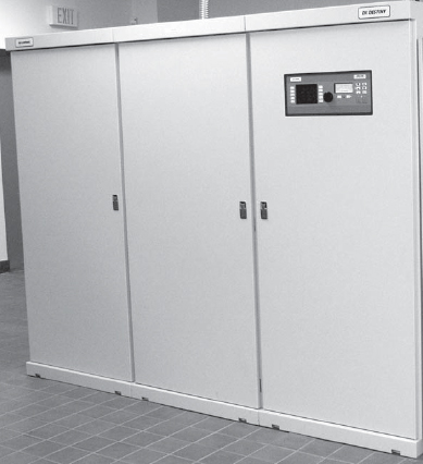
FIGURE 5-1
The Harris 3DX50, 50 kW AM transmitter. Digitally modulated transmitters are generally HD Radio ready.
As a general rule, tube-type AM transmitters cannot be used to transmit an AM HD Radio signal. Plate-modulated AM transmitters will distort the HD Radio waveform and will not have sufficient carrier phase stability to correctly pass the phase-modulated component of the digital portion of the HD Radio signal. Pulse duration–modulated (PDM), pulse width–modulated (PWM), and multiphase PDM transmitters will most likely not have the proper audio bandwidth to pass the HD Radio waveform correctly, and may distort the waveform. It may be possible, however, to correctly pass the HD Radio waveform through a multiphase PDM transmitter if the switching or sampling frequency employed is greater than 150 kHz. Digitally modulated AM transmitters, such as the Harris 3DX50 shown in figure 5-1, as a general rule, will work properly with an AM HD Radio signal.
So the two basic tests, then, are:
![]() Is the transmitter RF path phase-stable? and;
Is the transmitter RF path phase-stable? and;
![]() Is the modulator bandwidth at least 50 kHz?
Is the modulator bandwidth at least 50 kHz?
You should check with the manufacturer of your transmitter for HD Radio transmission compatibility. Some manufacturers have modification kits for their transmitters to make them HD Radio compatible in a cost-efficient manner. If your transmitter cannot be made HD Radio compatible, it will need to be replaced.
5.5 Requirements of the AM antenna system
One interesting and funny thing about AM radio stations is that no two antenna systems are the same. I have seen stations with nine tower directionals that can transmit the HD Radio signal just fine. I have seen a nondirectional station, which uses a modified version of a Franklin antenna, not be able to transmit an HD Radio signal due to the narrowband nature of the antenna.
Regardless of your antenna system, you should perform a full impedance sweep over a frequency band ±30 kHz from carrier. The results of a typical impedance sweep are shown in figure 5-2. This sweep should be performed at the output of the transmitter. On the basis of this sweep, you will likely then need to phase rotate the load so that the appropriate load symmetry is presented to the final amplifier in the transmitter. Each transmitter brand is different, and the tuning network introduces a certain amount of phase shift to the signal. This will change the sideband Voltage Standing Wave Ratio (VSWR) as presented to the final amplifier. You should check with the manufacturer of your transmitter to obtain the proper phase rotation information.
First, your load ±5 kHz from carrier should be as flat as possible, preferably presenting no more than a 1:1.035 VSWR across this passband. The resistances should be equal on both sides of carrier, and the reactances should be of equal magnitude but of opposite sign. This is called Hermetian symmetry.
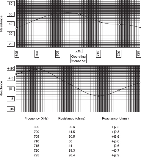
FIGURE 5-2
Impedance sweep of the WOR common point.
The purpose of the Hermetian symmetry area is to ensure that the HD Radio Digital Subcarriers that are in quadrature with the analog AM signal are transmitted symmetrically. There have been reports of a “bacon frying” sound in the analog audio of some stations. Part of this can be attributed to some tilt in the impedance in the Hermetian area, and the upper and lower digital sideband subcarriers not properly canceling in “normal” (i.e., non-HD Radio) AM receivers.
You also need to achieve a VSWR no greater than 1.5:1 over a passband of ±15 kHz. Each sideband should be as identical as possible. In this way, the HD Radio waveform will pass through the antenna system with a minimum of attenuation or distortion. A Smith Chart should be used to plot the load as shown in figure 5-3. You will then be able to tell if the load needs to be rotated in phase so that the correct VSWR range will be presented to the final amplifier.
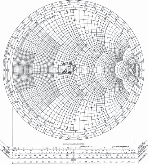
FIGURE 5-3
A Smith Chart of the antenna’s impedance sweep is used to determine antenna input bandwidth and proper phase rotation of the load for the transmitter’s final amplifier.
If you find that your antenna does not have the abovementioned characteristics, you may need to call in an RF consultant. There are many tricks that can be used to flatten out the impedance. What will work and what it will cost are pretty much determined by the results of your initial tests. Deciding to try the HD Radio signal through your system even if you cannot meet the above is up to you. It may perform adequately. It may not. It doesn’t hurt to try, though you may find that you cannot meet specifications for spectral regrowth, which will be discussed later in this chapter.
5.6 Installing the HD Radio equipment
First and foremost, the HD Radio exciter is a computer running the Linux operating system. While Linux is very stable and based on the UNIX operating system, there is a shutdown procedure Linux must go through, very much like that used by Microsoft Windows. It is strongly recommended that the HD Radio exciter be connected to power through an uninterruptible power supply (UPS), and that the UPS be connected to the exciter so that they talk to each other. In the event of a power failure, the exciter will stay up and will not crash. If there is no backup power available at the site, the exciter will shut down gracefully. This will prevent the corruption of files and the possibility that the station may be off the air for several minutes when power returns and the exciter reboots.
Next, be aware that a dual-trace oscilloscope and a spectrum analyzer are required for AM HD Radio installation. The oscilloscope should have a bandwidth of at least 50 MHz. The spectrum analyzer needs to be able to measure the AM broadcast band, and must be capable of a resolution bandwidth of 300 Hz. You should also have some type of HD Radio receiver available, one where you can split the analog audio off to the left channel, and the HD Radio digital audio off to the right channel (or vice versa) so they can be heard together. It would be preferable to use something like the Day Sequerra M4 or M2 monitors, or the Audemat-Aztec Goldeneagle HD AM. The radio is used to set the time delay between the digital and analog channels, and to assist in balancing audio levels between the analog and digital channels.
5.6.1 Connecting the HD Radio exciter to the transmitter
There are two signals that need to be inserted into the transmitter from the HD Radio exciter: the Magnitude signal and the Phase signal.
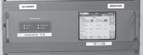
FIGURE 5-4
The Harris DexStar AM HD Radio exciter.
The Magnitude signal contains the analog AM audio, plus the HD Radio digital components that will amplitude modulate the transmitter. The Phase signal contains the station’s carrier frequency, plus the phase-modulated components of the HD Radio digital signal. You should have a supply of 50-ohm coax with BNC connectors available.
First, you have a decision to make. If you connect the exciter directly to the transmitter, which would be the easiest method, the transmitter will be tied directly to the HD Radio equipment. If the HD Radio exciter fails, you would need to switch to a different transmitter to maintain service.
We think of an exciter, shown in figure 5-4, as a piece of RF gear that feeds the transmitter and that is what the HD Radio exciter is, with a twist. The exciter is a computer which runs the Linux operating system. Linux is very stable. But it is still a computer. Things happen. A hard drive could go bad, a memory module could go bad, and in that case the exciter will fail. Sometimes it just needs to be rebooted. You need a fail-safe plan.
If instead of using a direct connection you connect the Magnitude and Phase signals through a switching circuit, then when the HD Radio exciter fails, the transmitter’s internal oscillator will switch in to drive the transmitter, and the audio processor’s analog output will switch in to put audio back on the carrier. This is the preferred method of installation, as it provides you with a fail-safe method to stay on the air, with an analog-only signal, in the event of exciter failure.
There are two methods by which you can accomplish this feat. By far the easiest would be to use equipment supplied by the manufacturer of your exciter and transmitter, as shown in figure 5-5. It is intended to fully interface with the exciter, and not only monitors the exciter for failure, but also monitors the RF output of the exciter to not only keep the station on the air, but to protect output Metal Oxide Semiconductor Field Effect Transistors (MOSFETs) in the event of a loss of drive.

FIGURE 5-5
The RF switchboard supplied by the manufacturer is the best way to connect the RF from the HD Radio exciter to the transmitter. This particular board has RF sensing which will switch the system to analog operation automatically should the RF output of the exciter fail.
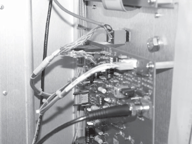
FIGURE 5-6
This is the relay used in WOR’s old Harris DX-50 transmitter to switch between the internal oscillator in the transmitter and the RF from the HD Radio exciter.
The second method is to simply use a small signal relay, an example is shown in figure 5-6, and connect it to the HD Radio equipment so that it will place the exciter online when commanded by the system.
WOR uses Harris DexStar exciters. These exciters have a companion called an e-Pal, which can act as an AES distribution amplifier and a rate converter. It also monitors the exciter, and switches the audio in the event of an exciter failure. With its companion RF switching board which installs in the Harris 3DX50 transmitter used by WOR (figure 5-5), a failure of RF output from the exciter will cause the switchboard in the transmitter to switch to the internal oscillator to keep the transmitter on the air and forces the e-Pal to switch analog-only audio to the transmitter’s input.
If you are using an older exciter or an exciter produced by another manufacturer, the e-Pal unit described above may be called an EASU (Exciter Auxiliary Services Unit). Some manufacturers build the EASU into the exciter. You will need to consult your manual and question the salesperson from whom you have purchased your HD Radio equipment.
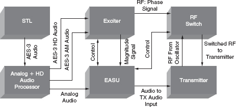
FIGURE 5-7
Block diagram of the AM HD Radio system showing how the equipment connects together.
The Magnitude output of the exciter connects to the EASU. The analog-only output of the audio processor also connects to the EASU. The EASU then feeds the audio input to the transmitter. Care must be taken to insure that the audio phasing is correct from the exciter to the transmitter’s input. If you find that your positive peaks are in the wrong direction, you can always flip the audio over in the audio processor. Correct audio polarity is critical for proper reproduction of the HD Radio signal. You will not be able to null the “spectral regrowth” and your transmitter will produce out-of-band emissions if the polarity of the magnitude connection between the input of the transmitter and the exciter is incorrect.
The Phase output of the exciter connects to one input of the RF switch. The internal oscillator in the transmitter connects to other input of the RF switch. The output of the RF switch connects to the external RF input on the transmitter. Please refer to Fig. 5-7.
The AES signals from the audio processor connect to their appropriate inputs on the exciter: the analog output to the analog input of the exciter, the digital output to the exciter’s digital input. Note that, in many cases, the AES-3 output of the audio processor, which contains the analog audio, is referred to as the analog output, while the analog audio input on the exciter is referred to as the analog input. This describes the content of the signal as being the analog audio. It does not mean that this is an analog signal: it is AES-3 data.
The non-AES-3 analog audio output of the audio processor then connects to the EASU to provide the transmitter with processed audio should the exciter fail.
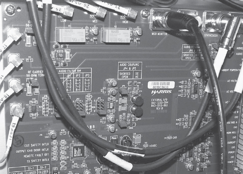
FIGURE 5-8
Any input filtering on the transmitter’s audio input board must be bypassed. If possible, the audio input should be set for AC coupling.
Any connections between the RF switch and the EASU should be made at this time. Additionally, any connections between the exciter and the EASU should be made in addition to any connections between the RF switch and the exciter. You will need to refer to your manufacturer’s literature. We will reserve connections to the station’s remote control system until later.
You should consult the manufacturer of your transmitter regarding the audio input stages of the transmitter. Most AM transmitters have audio filtering to prevent out-of-band emissions. These filters must be removed before you can attempt to put an HD Radio signal on the air. Figure 5-8 shows the audio input board and filter jumpers of the Harris 3DX50 transmitter. The typical 12-kHz filters used will not only eliminate part of the HD Radio waveform, but also distort the phasing of the HD Radio subcarriers. If possible, you will want to set the audio input on the transmitter for AC coupling.
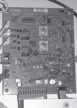
FIGURE 5-9
The output monitor of the transmitter may require adjustment to desensitize it to the HD Radio signal.
You should also consult with the transmitter manufacturer regarding the output monitor in your transmitter, see figure 5-9. All AM transmitters monitor the output for things such as VSWR and automatic power control. If the output monitor is too sensitive, it may mistake the HD Radio waveform as carrier pinch off and/or a VSWR condition, and will momentarily kill the output of the transmitter. This is annoying on the analog audio channel, as the audio will have pops in it. It can be devastating to the digital audio channel, as the radio will not have time to lock onto a stable digital subcarrier. You may find that, after making the initial adjustments on reduced power, you may need to spend time calming down and readjusting the transmitter’s output monitor.
5.6.2 Connecting the GPS
The HD Radio exciter comes with a Global Positioning System (GPS) antenna. The GPS data provides the exciter with a highly accurate timing reference plus location information. Having your exciter GPS locked will also ensure carrier frequency stability, which will help listener’s HD Radio receivers lock onto the various HD Radio stations in any given city faster. In the future, it may be possible to transmit the correct time to listener’s radios. The GPS antenna needs to be mounted somewhere outside the transmitter building, perhaps on an STL antenna mount, (see figure 5-10) and its coax cable connected to the exciter.
The HD Radio exciter is designed to work with GPS data. It is strongly suggested that you provide this connection so the exciter does not lock up. If you find that for some reason you cannot connect the GPS antenna, it is possible to tell the exciter that it does not have a GPS antenna associated with it. However, it is best to have the GPS antenna connected and the GPS service activated in the exciter.
It is interesting to note that you can use either 50-ohm or 75-ohm cable should you need to extend the length of the coax that comes with the exciter’s GPS antenna. Just make sure to calculate the delay caused by the length of cable you use (this information is in the exciter’s manual), as you will enter this figure into the exciter’s configuration later.
5.6.3 Preliminary checks
Next, before you boot up the exciter, make sure the output of the transmitter is terminated into a dummy load. You should not put the transmitter on the air and make adjustments unless it is absolutely necessary to do so, as chances are very good that you will initially produce out-of-band emissions. If you need to perform your initial adjustments into the antenna system, you should probably perform them after midnight.
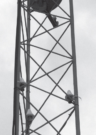
FIGURE 5-10
The supplied GPS antenna needs to be placed where it has a good view of the sky, such as on the station’s STL tower.
First, you will want to make sure that your switching unit is working correctly. With the exciter off, you will want to use an oscilloscope to check for analog audio at the input to the transmitter. With the exciter off, the EASU will sense the failure and should present the transmitter with the analog audio input. If this is not the case, you should troubleshoot and find the problem.
You should also, at this time, check to make sure that, with the exciter off, the transmitter’s internal oscillator is connected to the transmitter’s external RF input through the RF switch. This can be done by disconnecting the BNC plugs to and from the transmitter and measuring with an ohmmeter, (see figure 5-11) as a start, if you are using a simple relay switch. If you are using an interface from the transmitter’s manufacturer, you can use an oscilloscope to see if an RF signal is present. The transmitter’s power output should be ramped down to zero for this test. Once you are sure you have continuity from the oscillator to the external RF input, you can reconnect the plugs and consider bringing the transmitter up. The purpose of this test is to make sure you will have RF going to the transmitter’s amplifier. If you attempt to bring the transmitter up, and the underdrive sensing circuit fails with no RF present, you may find yourself with many burned up MOSFETs.
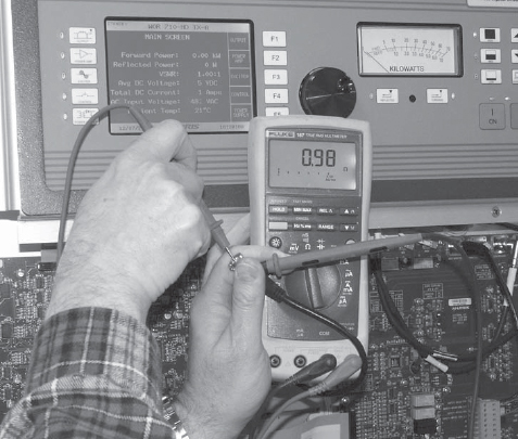
FIGURE 5-11
Checking the RF switch’s continuity with a multimeter.
You will need to use an oscilloscope to measure the level of the RF signal being supplied by the oscillator circuit in the transmitter. Some transmitters have the oscillator active while the transmitter is off (see figure 5-12). If so, use the oscilloscope to measure the peak-to-peak RF voltage with the oscillator connected to the transmitter’s external RF input. The external RF input will present a load, usually 50 ohms, to the incoming signal. You need to measure this voltage with the load, not open circuit.
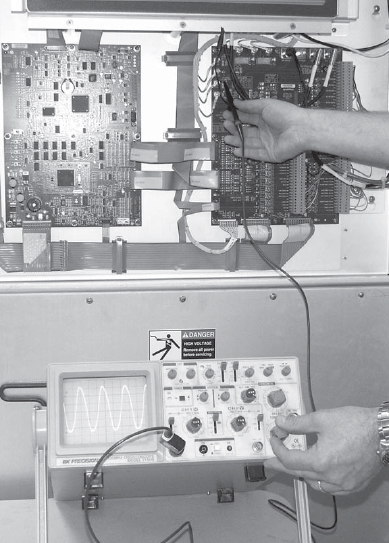
FIGURE 5-12
It is important to check the peak-to-peak RF voltage being delivered to the transmitter by the transmitter’s internal oscillator and then match the output of the HD Radio exciter to the same level.
Turn the transmitter on briefly and make sure the peak-to-peak RF voltage does not change with the transmitter on. Write down this peak-to-peak level. You should also make note of and write down the power amplifier (PA) drive indication on the transmitter for comparison with the HD Radio equipment in line.
5.6.4 Initial boot up of the exciter and initial setup
You should now turn the HD Radio exciter on. It will take a short while to boot up. Let it fully boot. You will be fully booted when the GUI comes up and is no longer presenting you with booting messages. Do not be concerned that the GPS is unlocked at this time. It will take a few minutes for the GPS signal to lock under a normal boot up. Since this is the first time you have booted up this exciter in this location, it could take as long as 15 minutes. The GPS signal will eventually lock.
From this point on, you will see certain system commands listed in italics type. The commands listed in this chapter are based on irss version 2.3.3, operating system version 7.1, and operating system kernel 2.4.20–22 of the iBiquity Digital Corporation HD Radio software.
You first need to check the screen to make sure the exciter is operating on the correct band at the correct frequency. Locate the carrier frequency and make sure it is set to your station’s frequency. If it is not, you will need to navigate to the System Setup area of the GUI and reset the band and frequency. This will force a reboot of the exciter. You will need to enter the password of the exciter to access the setup areas. Refer to your exciter’s manual to get the default password. It is usually 1234, or 123456.
The exciter has a touch screen. Touch the Password Block, and a virtual keyboard will appear on the screen (see figure 5-13). Enter the default password, then hit the virtual ENTER key.
If you are the only person who has access to the exciter, you do not need to change the default password. If, however, the exciter is accessible by many people, it is a good idea to change the password so that curious fingers do not change the system settings, possibly taking the station off the air or causing the transmitter to emit out-of-band products. You will note that there is a button near the password entry field that will allow you to change the password. If you do change the password, make sure it is something you will not forget.
If you needed to change the carrier frequency, the exciter will prompt you for a reboot. Note that the exciter needs to be rebooted for this change to take effect. Select YES to allow the exciter to reboot.
5.6.5 Setting the GPS parameters
Navigate to the System screen, then to the Network GPS screen, and then to the GPS Configuration screen. Enter the delay, in nanoseconds, that you calculated for the length and type of cable you are using for the GPS antenna into the Antenna Delay field. This information can be found in the exciter’s manual. Select your Time Zone, and select Daylight Saving Time if your area observes Daylight Saving Time. If there is a check box for GPS Time Synch, it should be checked.
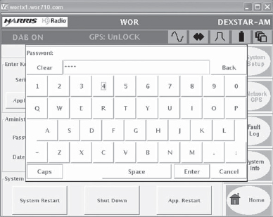
FIGURE 5-13
Password entry is made through a virtual keyboard on the exciter’s touch screen.
5.6.6 Setting network parameters
Once the exciter is on the correct frequency, one of the first things you should do is set up the networking parameters. This can be found under the System menu as Network Configuration. Some manufacturers, like Broadcast Electronics, have a procedure to set networking parameters that require you to go to a Linux command line for setup. Consult your manual.
The first thing in this list is the Hostname, the networking name of the exciter. I used “wortx1” and “wortx2” as the hostnames for the two exciters that I have. DO NOT enter a space or other illegal character into the hostname field. Doing so will cause the exciter, on next reboot, to go into a reboot loop that you will not be able to escape out of. In this case, you will most likely end up sending the exciter back to the factory, as the manufacturers are under contract not to give out the root password for exciters. I know that as of the writing of this book, Harris has instituted a warning screen that catches illegal characters and warns you to change what you have input effective after irss version 2.2.5. Generally, any letter or number, and a dash (-) or underline (_) is acceptable.
The next field is the Domain field. It is OK to leave this field as it is, unless you will be connecting the exciter to a LAN that uses a domain server. If your LAN uses a domain server, you should enter the correct domain name in this field.
There is a row of buttons at the bottom of the Network Configuration screen. If you will be sending the exciter PAD via Ethernet, you should select the Static IP button and assign the exciter a static IP address. This is true also if you intend to utilize Virtual Network Computing (VNC) to get into the exciter remotely. VNC will be discussed later. If you will not be using a Static IP address, you can select Dynamic Host Configuration Protocol (DHCP) and the exciter will be assigned an IP address from your DHCP server. If your exciter will not be on a LAN, you can select Off Net.
If you have chosen to assign your exciter an IP address, you will need to enter the IP address, the subnet mask used on your LAN, and the Internet gateway address. If you do not know these items, you should get the information from your company IT department.
Depending on the software version that is running on the exciter, you may also see two fields called Exciter Link and Exciter MAC. These fields are used in FM Exporter systems and are not used for AM HD Radio exciters. Exciter Link will display a grayed out “local host” IP address of 127.0.0.1. Exciter MAC will be blank.
When you have entered all the information, and double-checked to make sure you do not have a space in the hostname field, you should select the Save Cfg button. The information will be saved, and you will be prompted to reboot the exciter.
Once the exciter has rebooted, you should go to the Mode Control screen, and turn the Digital Subcarriers off. You will find a virtual button to do this on the Mode Control screen.
5.6.7 Setting the RF output level of the exciter
If you are using an EASU, you should now place the system into Operate mode. Older EASUs have a rocker switch that needs to be switched to the Operate position. The newer EASUs, like the Harris e-Pal, have a push button. Once the system has been placed in Operate mode, if your EASU has an operational indication, it will be lit.
Take your oscilloscope and measure the RF level at the output of the RF switch. To make sure you are seeing RF from the exciter, momentarily disconnect the cable coming from the internal oscillator of the transmitter. If the RF goes away, your RF switch did not switch to the output of the exciter, and you will need to troubleshoot this. You want to be sure you are looking at the RF coming from the exciter.
Compare the peak-to-peak voltage measurement of the RF from the exciter with the measurement you made with the transmitter connected to its internal oscillator. If the RF from the exciter is higher or lower than what was coming from the transmitter’s internal oscillator, you will need to adjust the RF output of the exciter.
The RF output adjustment may be in different locations depending on the manufacturer. It may be on the Digital Upconverter (DUC) board in the exciter, it may be on the RF switching interface installed in the transmitter, or it may be on the back of the exciter (see figure 5-14). Refer to your exciter’s manual to determine where is the exciter’s RF output adjustment.
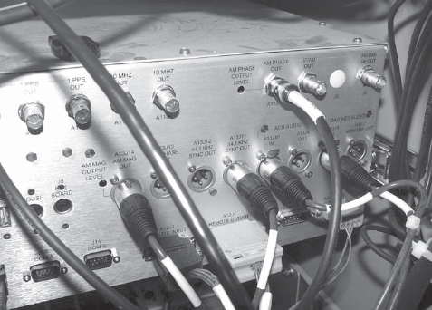
FIGURE 5-14
In the case of the DexStar, the RF level adjustment, sometimes called the Phase Level, is on the back of the exciter.
Move the oscilloscope into a position where you can observe the RF level at the output of the switchboard, and adjust the output of the exciter to the same peak-to-peak output the transmitter sees from its internal oscillator. Once this is done, you should switch between the internal oscillator and the HD Radio exciter to make sure the RF level seen by the transmitter does not change.
5.6.8 Setting the analog audio bandwidth
Go back to the exciter, and navigate to the AM System Setup screen (see figure 5-15). Make sure the Analog Modulation virtual button is On. You will also need to make a decision. The audio bandwidth of the analog audio can be set in the audio processor, or you can allow the HD Radio exciter to perform the audio bandwidth reduction. I prefer to have the audio processor do the bandwidth reduction. Very simply, the audio processor is designed to perform the audio roll off gracefully and it will sound good. The audio filter in the exciter is designed to protect the HD Radio subcarriers. I do not like the sound of it, as it is rather harsh.
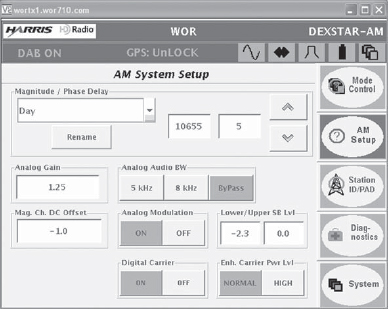
FIGURE 5-15
It is important to tell the exciter what bandwidth mode it will be operating in, as the exciter will instruct the radio how to handle incoming data.
If you are letting the audio processor handle the audio bandwidth reduction, set the Analog Audio BW setting to Bypass by pressing the Bypass virtual button. By default, setting the Analog Audio BW on the exciter to Bypass tells the exciter to operate in the 5-kHz transmit mode. You cannot run the audio processor with a bandwidth of 8 kHz in this mode – the excess audio bandwidth will interfere with the HD Radio subcarriers, and the radios will be told by the exciter that it is operating in 5-kHz mode (see figure 5-16). If you intend to operate with an audio bandwidth of 8 kHz, you will need to press the 8-kHz button. Once you have made your selection, leave the exciter on this screen. We will be working with it shortly.
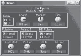
FIGURE 5-16
You will need to set the bandwidth of the audio processor if you select “bypass” as the bandwidth mode on the exciter.
5.6.9 Setting the analog audio level into the exciter
Next, we are going to set the audio level into the exciter for the analog channel. The exciter builds the entire AM HD Radio waveform internally, much in the same way the AM stereo exciters did in the 1980s, for reference purposes. We need to input a tone to the exciter and set the internal modulation level.
On the Mode Control screen of the exciter’s GUI, press the Digital Carrier OFF button. You do not want the HD Radio subcarriers to appear for adjustment at this time – we are only looking for analog audio modulation levels.
Set the audio processor to produce a test tone, and set the AM output level of the processor to –3 dBFS (decibels full scale). If your audio processor does not have the ability to send a test tone, you will need a good audio test set, such as the Audio Precision test set, with an AES-3 output.
You could send an analog tone from a test set through an A-to-D converter. The tone frequency can be 400 Hz or 1 kHz, set to –3 dBFS.
On the back of the exciter, you will find a BNC connector labeled AM Out. Connect the AM Out of the exciter to the input of your oscilloscope. Set the oscilloscope so that you can observe a modulated AM carrier. With the tone output of the audio processor set to –3 dBFS, you should observe 95 percent AM modulation (see figure 5-17). The negative modulation envelope should not be cut off. If you do not see 95 percent negative modulation, you will need to make an adjustment on the exciter.
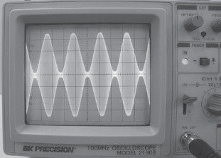
FIGURE 5-17
Set the internal modulation of the exciter to 95 percent.
If you do not see 95 percent modulation, go to the AM System Setup screen on the exciter and make small adjustments to the Analog Gain setting. Touch the Analog Gain block, and the virtual keyboard will appear. The default setting is 1.0. If you need to increase the modulation, enter in 1.1 and see where that takes you. If you need less modulation, enter in 0.9 and see where you end up. Once you have achieved 95 percent modulation, it is time to set the audio level into the transmitter.
5.6.10 Setting the audio level into the transmitter
Bring the transmitter up into the dummy load running on the RF from the HD Radio exciter. The transmitter will be up for a while, so set it to a relatively low level, say, one-quarter power.
Take a DC voltmeter, and measure the DC voltage across the audio input to the transmitter (see figure 5-18). It should be zero volts. If it is not, you will need to adjust the DC Offset setting in the AM System Setup screen of the exciter to produce zero volts DC at the input to the transmitter. The normal setting for DC Offset is –1.0.
Once you have obtained zero-volts DC at the input to the transmitter, check the modulation of the transmitter. It must match the 95 percent obtained when you measured the AM Out jack on the exciter. If it is not 95 percent, you will need to adjust the AM Magnitude pot most likely located on the back of the exciter.
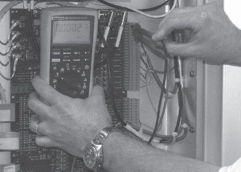
FIGURE 5-18
The DC offset into the transmitter should be zero volts.
Do not make any adjustments to the audio input level in the transmitter. The audio level to the transmitter must be adjusted at the exciter. Place the oscilloscope where it can easily be seen, and adjust the AM Magnitude pot to produce 95 percent modulation of the AM transmitter (see figure 5-19).
Once you have obtained 95 percent modulation on both the AM Out jack of the exciter and of the transmitter, you should increase transmitter power to full power output and reset the AM Magnitude pot on the exciter as necessary to obtain 95 percent modulation at full power. Then, shut off the test tone and modulate with program material, observing both the AM Out jack of the exciter and the output of the transmitter. You should ensure that you are not hitting negative modulation peaks of any greater than 95 percent.
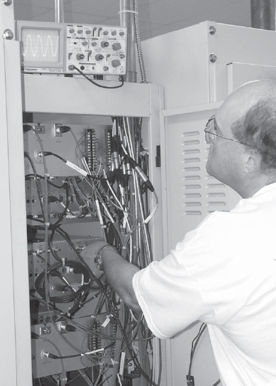
FIGURE 5-19
Use the AM Magnitude adjustment to set the modulation of the transmitter to 95 percent.
Carrier pinch off can do several things. First and foremost, if the carrier disappears, an HD Radio receiver will glitch as the incoming data will be disrupted. It will also cause false VSWR trips of the transmitter, and could, in extreme circumstances, cause damage to the transmitter, such as blown output MOSFETs. If you observe modulation greater than 95 percent, adjust the output of the audio processor to bring them to 95 percent negative. Do not adjust the Magnitude adjustment on the exciter to do this.
The correct adjustment of the Magnitude level into the transmitter is critical, as the primary HD Radio subcarriers are injected through the audio input of the transmitter. Once you see that the transmitter is producing 95 percent modulation with tone as the exciter does, you should not adjust the AM Magnitude pot on the exciter any longer. Return the transmitter to reduced power operation unless you are certain your dummy load will be able to function properly at full power with modulation for an extended period of time.
5.6.11 Setting the HD Radio subcarrier levels and adjusting for best performance
We are now ready to check the levels of the HD Radio subcarriers as well as make adjustments to bring the “spectral regrowth” and out-of-band emissions down to legal levels. You will need a spectrum analyzer for these adjustments (see figure 5-20). Not only will the spectrum analyzer need to be capable of measuring at the frequency of an AM station, but it will also need to be able to operate with 300-Hz resolution bandwidth. The spectrum analyzer will also need to be capable of running and displaying an average of at least 100 sweeps.
Before we connect the spectrum analyzer, it should be said that the biggest mistake people make when setting up their first AM HD Radio station is that they perform the next set of adjustments far too fast. This is going to take you several hours. It cannot be done in 10 minutes. The more time you spend making these adjustments, the better your HD Radio system will perform.
Connect the spectrum analyzer to the transmitter sample port through RF attenuators. When performing this adjustment, it is critical that the front end of the spectrum analyzer not be overdriven. This could cause false measurement of the spectral regrowth region, as an overdriven front end will produce harmonics and splatter that is not actually present, and it will be displayed on the analyzer as such. Note that when setting the input level of the spectrum analyzer, all signals present must be taken into account, not just carrier.
Once you are sure that the spectrum analyzer is not being overdriven, you need to set it up correctly. First, set the center frequency to your station’s frequency. Set the span to 100 kHz, so that you are seeing ±50 kHz on each side of the carrier. Set the amplitude of the carrier so that it just touches the top line of the graticule. You want at least 80 dB of measurement headroom. Set the resolution bandwidth to 300 Hz, and the video bandwidth to 1 kHz.
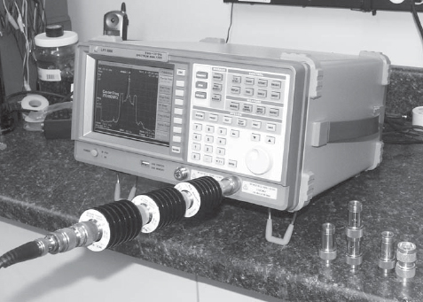
FIGURE 5-20
The spectrum analyzer is used to correctly adjust the system for the correct HD Radio waveform.
Refer to the manufacturer’s instructions. They will indicate a starting point for the Magnitude/Phase Delay setting for your transmitter. Make sure the Magnitude/Phase Delay is set to the starting number as specified by the manufacturer.
Navigate to the Mode Control screen on the exciter’s GUI, and turn the Digital Carriers on. Navigate back to the AM System Setup screen.
You may notice that your transmitter starts to hiss. This is normal and is nothing to be concerned about. You are simply hearing the HD Radio waveform from the transmitter the same way you hear the analog modulation ring in the tuning components. It is very disconcerting at first, as most of us associate this sound with either a pressure leak in a transmission line or with something arcing over. Nothing will burn up. This is a sound you will eventually get used to.
You should now see “shoulders” on your signal as displayed on the spectrum analyzer. You will also most likely be looking at a lot of “junk” on each side of the HD Radio waveform (see figure 5-21). In particular, you will most likely see large humps centered ±25 kHz, give or take, from carrier.
These humps are called spectral regrowth. They are an intermodulation product and reflection of the primary HD Radio carriers. The primary HD Radio carriers, remember, are located at 10–15 kHz from carrier. The spectral regrowth located –25 kHz from carrier is related to the upper HD Radio primary sideband. The spectral regrowth located +25 kHz from carrier is related to the lower HD Radio primary sideband.
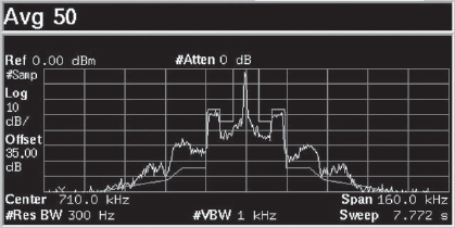
FIGURE 5-21
You may have a mess on the spectrum analyzer when you first bring the transmitter up. Adjusting the Magnitude/Phase Delay will bring the out-of-band products under control.
There are numerous things that cause these reflections, for example, modulator, PA, and antenna system bandwidth. The primary contributor to spectral regrowth tends to be the alignment of the magnitude and phase signals through the transmitter RF chain, which will cause intermodulation products if the modulator, PA, and antenna system bandwidth is not optimal. The tertiary and secondary HD Radio subcarriers phase modulate the carrier. The primary HD Radio subcarriers amplitude modulate the carrier. The timing of these portions of the HD Radio waveform must be correct or spectral regrowth develops.
First things first, however. Measure the level of the upper and lower HD Radio Primary sidebands at ±12.5 kHz. To do this, set the spectrum analyzer to average, and for now simply do an average of 30–40 sweeps. The level of the primary HD Radio carriers should be –28 dBc (–27.8 dBc is the maximum allowable) as referenced to carrier level. You may find this relatively easy to measure if you average, then set a marker on the carrier, and use a delta marker to measure the level of the HD Radio subcarriers.
If they are not –28 dBc, you can adjust them on the AM System Setup screen. Simply touch the number block in the area where it says Lower/Upper SB Level. This number is in dB. If you need to bring the lower sideband down, say 1.2 dB, enter –1.2 on the virtual keyboard that comes up when you touch the Lower SB Level block. Restart the average on the analyzer and check to make sure your adjustment was correct. You want both HD Radio Primary sidebands equal in level at –28 dBc.

FIGURE 5-22
The correct HD Radio waveform after making the magnitude and phase adjustments.
We are next going to minimize the spectral regrowth. While the FCC mask says that we can have energy up to –35 dBc in this area, know that spectral regrowth is directly related to transmitted data errors. The higher the spectral regrowth, the more errors we are transmitting; the more errors in the signal, the less digital coverage your station will have. The idea is to minimize the reflections being caused, thereby minimizing the transmitted data errors. We are aiming for a number below –65 dBc, as this is the level called for in the NRSC-5 IBOC mask. Adjusting the timing and aligning the portions of the HD signal contained in the Magnitude and Phase signals will minimize the spectral regrowth.
Another reason to minimize spectral regrowth is to minimize interference to third adjacent stations. The spectral regrowth will appear as a hiss under a third adjacent signal. Minimizing the spectral regrowth as much as possible is being a good neighbor.
You will notice two blocks in the Magnitude/Phase Delay area of the AM System Setup screen. The block on the left is the Magnitude/Phase Delay adjustment. The block on the right is the amount that will be adjusted by pressing an Up or Down arrow. Set the right-hand block to 100 by pressing the block and entering it into the virtual keyboard.
Restart the averaging on the spectrum analyzer, set a marker on the carrier, and set a delta marker on either spectral regrowth hump, at either –25 or +25 kHz, or where the hump is highest. When the average is complete, read the delta marker and write this figure down so you don’t forget it.
Go to the AM System Setup screen on the exciter and write down the Magnitude/Phase adjustment number next to the delta marker measurement on your notepad. This is your starting point. Press either the Up or Down arrow located in the Magnitude/Phase Delay area. Because we don’t know which direction will make the spectral regrowth better, just pick a direction. When you hit that arrow, you will notice the Magnitude/Phase adjustment number changes by 100 in whichever direction you picked. Write this new number down on your notepad.
Restart the averaging on the spectrum analyzer. When the average is finished, reset your marker on carrier, read the delta marker on the spectral regrowth hump, and write it on your notepad next to the Magnitude/Phase Delay adjustment number you wrote down previously. The level of the delta marker will have gotten lower, higher, or not changed. If it has increased or not changed, we are going in the wrong direction with the Magnitude/Phase Delay adjustment. If it has decreased, we are going in the right direction. If we have gone in the wrong direction, go back to the exciter and hit the opposite arrow from the one you pressed last two times. If you are going in the correct direction, press the same arrow you pressed one time. Write the new Magnitude/Phase Delay adjustment number on your notepad.
Restart the averaging on the spectrum analyzer. When the average is finished, read the delta marker again. Keep repeating these steps until you find the place where the spectral regrowth appears to bottom out. You will notice with each adjustment that the spectral image of your signal keeps getting better (see figure 5-22).
Once you have found the apparent null in the spectral regrowth, you will need to reset your average to at least 100 traces on the spectrum analyzer, then let the analyzer average. This will take roughly 5–10 minutes.
At the end of the average, you will want to set a marker on carrier, and set a delta marker at –25, –12.5, +12.5, and +25 kHz. The readings obtained at ±12.5 kHz will be the level of the primary HD Radio subcarriers. If it is not – 28 dBc, go to the exciter and reset the Lower/Upper SB Level adjustments. The markers at ±25 kHz are the spectral regrowth measurement. This is a coarse adjustment, as we were looking for it to bottom out and were adjusting by 100. We also were only averaging 40 times.
Write the measurements obtained by the delta markers at –25 and + 25 kHz on your notepad, along with the Magnitude/Phase Delay adjustment number on the exciter. The adjustment range in the right-hand block is now set to 100. Set this number to 10. Select the Up or Down arrow and press the one you selected. The Magnitude/Phase Delay adjustment number will increase or decrease by 10. Write the new number down on your notepad. Restart the average on the spectrum analyzer. We will be doing 100 sweep averages from this point forward.
Once the average is complete, reset the marker on carrier and measure the delta markers at ±25 kHz again. Repeat the Magnitude/Phase Delay adjustment and reset the averaging steps until you have obtained the apparent null of the spectral regrowth.
We will not fine-adjust the spectral regrowth until we put the transmitter back on the antenna. The adjustment may change due to antenna bandwidth.
On the exciter, go to the AM System Setup screen and turn the Analog Modulation on. Note that you will not be able to accurately read analog modulation with the HD Radio subcarriers on. Your modulation monitor will indicate that you are overmodulating (see figure 5-23). This is normal. If you need to measure and set analog modulation, you will need to shut the HD Radio subcarriers off to do so. Turn the HD Radio subcarriers back on when you have completed adjusting the analog modulation. You will find the Digital Carriers On/Off buttons on the Mode Control screen.
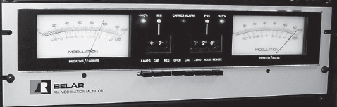
FIGURE 5-23
When the HD Radio subcarriers are on, the modulation monitor will show apparent overmodulation. This is normal, as the monitor is responding to the extra energy caused by transmission of the HD Radio digital sidebands.
See how the transmitter is behaving while operating into the dummy load. If it seems stable, bring it up to full power. If the transmitter seems to glitch and/or back its power down, you will need to adjust the output monitor on the transmitter. Once the transmitter is stable, it is time to put it on the air at full power.
5.6.12 Putting the transmitter on the air and fine-tuning the spectral regrowth
Navigate to the Mode Control screen on the exciter and turn the Digital Carriers off. Put the transmitter on the air and measure the modulation on your modulation monitor. You want to adjust the AM output of the audio processor so that you are not exceeding 95 percent negative modulation peaks. Contrary to what you may have heard, you can modulate the transmitter with 125 percent positive modulation when you are running HD Radio. Most manufacturers say that you should adjust the positive peak control on the audio processor for 140 percent, as the exciter will limit the positive peaks. I set WOR’s positive peaks on the processor to 125 percent and leave them there. I don’t trust the clipping in the exciter, but the choice is yours.
Once you have your analog modulation set, go back to the Mode Control screen on the exciter and turn the digital carriers on. Let the transmitter sit with the HD Radio subcarriers on for a few minutes to make sure it is stable. You may find that you need to fine-tune the output monitor now that the transmitter is operating on the antenna. You may notice that your modulation monitor is indicating –100 percent modulation and high positive peaks. This is normal with the extra energy in the sidebands caused by the HD Radio subcarriers and is nothing to worry about. Your analog modulation did not increase and you are not overmodulating.
Once you are sure the transmitter is stable, recheck the carrier level on the spectrum analyzer and then set it to average at least 100 times. While you are waiting for the spectrum analyzer to average, go to the exciter and navigate back to the AM System Setup screen.
Once the analyzer has averaged, set a marker on carrier, and a delta marker on either spectral regrowth hump at –25 or +25 kHz. Measure the spectral regrowth. It should be close to the reading you obtained on the dummy load.
Reset the adjustment step for the Magnitude/Phase Delay on the exciter to 1. We will now fine-tune the spectral regrowth. Press either the Up or Down arrow, and write the new Magnitude/Phase Delay adjustment down. Reset the averaging on the spectrum analyzer. When the average is done, set your carrier marker and read your delta marker. Repeat to minimize the spectral regrowth, which should now be well below –65 dBc (see figure 5-24). You may need to do this several times to find the absolute minimum.
Once you have found the absolute null of the spectral regrowth, set delta markers again at ±12.5 kHz and measure the level of the primary HD Radio subcarriers. If they are not –28 dBc, make the appropriate adjustments on the AM System Setup screen. If you need to adjust the primary HD Radio subcarriers, you will need to average again and check to make sure the primary HD Radio subcarriers are where they belong.
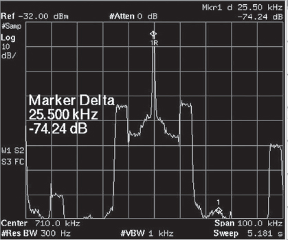
FIGURE 5-24
The HD Radio waveform showing a marker on the spectral regrowth. This was measured in the field at a location 2.3 miles from the transmitter site. The pieces of HD Radio waveform you see on the left and right are WFAN and WABC, respectively.
Once you have done this and are sure the system is correct, take a screen shot of the spectrum analyzer for your records. There are several ways to accomplish this depending on your spectrum analyzer. I prefer to save the screen shots to a flash drive and print them later from a photoediting program. You may want to take several screen shots with the delta markers and their readings on the screen.
After you have taken a screen shot, reset the span on the spectrum analyzer for 200 kHz, reset the carrier level, and then restart the averaging again. When the average is complete, take a screen shot for your records. You may need to set a marker on carrier and delta markers on any significant bumps you may see on the display. This average will show complete compliance for mask purposes. If you have other stations nearby, they may appear on the analyzer if they are picked up through the antenna and seen at the transmitter’s sample port (see figure 5-25). Make sure you know which stations they are so that you can identify them in your performance report.
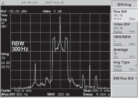
FIGURE 5-25
The 200 kHz span screen shot of the spectrum analyzer, looking at the WOR signal. WFAN is on the left of the WOR signal: WABC is on the right.
If you operate with separate antenna configurations day and night, you should perform the Magnitude/Phase Delay alignment again on the nighttime antenna. You can start with the final numbers you obtained going through the procedure the first time, and fine-tune from there. You can change to nighttime mode on the AM System Setup screen, then perform your Magnitude/Phase Delay adjustments to fine-tune the spectral regrowth null for the night antenna. Make sure to save the spectrum analyzer screen shots. You will need one at a span of 100 kHz, and another at a span of 200 kHz.
Once your system has been set up and the spectral regrowth has been minimized, you should take a set of spectral measurements in the field to make sure everything is okay. Many times, the monitor port on a transmitter will skew the measurements or may not show the signal as it will actually pass through the antenna. I have located a place approximately 2.3 miles in front of the WOR array that is clear of obstructions where we have a measured 1.5 volts per meter of signal (see figure 5-24).
The location you choose should be free of reradiating structures and, if you are directional, should be in the center of the main lobe of the signal. You will need to make and save spectral measurements with a span of 100 and 200 kHz for both day and night patterns, if this applies. If you find anything that looks incorrect, you may wish to make further adjustments to the exciter.
You may also, at this time, wish to take a spectral reading and save the measurement using the peak-hold feature of the spectrum analyzer rather than the averaging feature to prove compliance with the FCC regulation 73.44 as relates to allowable emissions. Note that this measurement should be at 200-kHz span, and that, because the peak values of the HD Radio subcarriers are higher than the average values, your primary HD subcarriers and spectral regrowth will appear higher. The idea of this measurement is to show full compliance with 73.44, not to adjust the HD Radio system.
You have now completed the RF alignment of your HD Radio system. You should print the screen shots you made after all of your adjustments were complete and write a report showing compliance with the FCC and NRSC-5 IBOC mask. This report should go into the station’s files as annual performance measurements and compliance should the FCC wish to see it.
5.6.13 Adjusting the audio time delay
Next, you need to complete the audio alignment of your system. For this, you will need an HD Radio modulation monitor, such as the Day Sequerra M2 (see figure 5-26) or the Audemat-Aztec Goldeneagle HD AM. You can also use a car or home HD Radio receiver, but it must have the ability to split the analog and digital audio so that one stream is on the left channel and the other is on the right channel. You will also need a pair of headphones, as this is the easiest way to hear the delay correctly in the noisy transmitter room.
They say that a first impression is everything. It is extremely important that the time delay of the analog audio channel be as close as possible to the delay of the digital audio channel. If the first impression a listener has of your HD Radio signal is disjointed audio when his or her radio blends between analog and digital audio, they may not come back for a second listen.
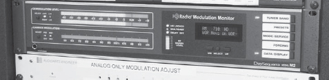
FIGURE 5-26
The Day Sequerra M2 allows the audio to be split so that the analog audio signal can be heard on the left channel and the digital audio signal can be heard on the right channel. This helps simplify setting the time delay.
On the exciter, navigate to the Audio Setup screen. Check to see if you are “ramped in” to delay on the analog channel. To check this, look in the Ramp Control section. It will list a Final and Current delay. If they are zero, you are not in delay.
Under Delay Adjustment, set the New Delay to 8.4 seconds. This will be a good starting point and should be very close to the final delay you need. Set the Ramp Rate to 100. If you wish, because you most likely want to get into delay quickly, you can set the ramp rate to a lower number, but if you are doing this in the middle of the afternoon, it will be highly noticeable on the air in the analog channel, as with the ramp rate set to 100, the system adds or subtracts one sample for each 100 samples. At a lower ramp rate, this addition or subtraction of samples becomes audible. Press the Up arrow under Ramp Control. You will see the Current Delay start to increment up. When this has reached 8.4 seconds, put the headphones on.
You will notice that the analog audio is on one channel, possibly the left, and the digital audio will be on the opposite side, possibly the right. Pay very close attention and see if you can tell if one is ahead of the other. You can easily change the delay time by changing the New Delay field under Delay Adjustment and walk it in. When you are finished, make sure the Blend Control on the exciter is set to Enable Blending, then set the radio or monitor back to normal mode. You should notice a quality change when the radio blends from analog to digital, but they should not be out of sync. The blend should be very smooth. You should also reset the Ramp Rate to 100 at this time if you changed it.
If you wish to get the timing between the channels as close as possible, you can set your radio or monitor to split mode and record both channels on a digital editor. You should then be able to measure the exact time delay between both the analog and digital streams, and make the adjustment on the exciter to make them exact.
You may wish to spend some time getting the digital audio channel to sound the way you want it to. Note that there will be an approximate 8.4-second delay from the time you make an adjustment on the processor until the time you hear it on the radio. You will find that this takes some getting used to.
You will also want to balance the levels between the analog and the digital audio channels so the blend will not have an abrupt level change. To do this, do not adjust the output of the processor for the analog channel. Adjust the output of the digital channel of the processor. Because your analog channel is the one most persons are listening to, and because it has modulation limits imposed by FCC regulation, let the analog channel be the standard. Adjust the levels of the digital channel to the analog channel, not the other way around.
Let the radio blend from analog to digital. Make your level adjustment on the digital output of the processor, wait 10 seconds, and then make the radio blend again. You may need to do this several times to get the levels exact.
5.6.14 Entering station-specific text information
Before you complete the setup and installation of the exciter, there are a few things left to input. Navigate to the Station ID screen on the exciter.
Do not attempt to change the frequency listed on this screen. This is your station’s carrier frequency, and changing this will cause the exciter to operate on the wrong frequency.
FIGURE 5-27
Some HD Radio receivers will display the Long Station Name SIS data field. Make sure it is something you would want the public to see.
Under Station Information, enter the station’s call letters where indicated. The station’s call letters will appear on a listener’s radio when they first tune to your station. The Country Code should be 1 for broadcasters in the United States. The Network Code should be what the manufacturer tells you it should be. The Facility ID should be your FCC facility ID as listed in the FCC database.
The Long Station Name field can be something like your corporate name or station’s slogan see figure 5-27. WOR’s says, “Real Talk Radio”. The Long Station Name field will appear on some receivers, but not others, so don’t put something off-color in this field as a joke. And do not leave it blank. This field must be filled. You will notice that Harris puts the serial number of your exciter in this field just to have something in there. Please don’t transmit the serial number of your exciter. It looks ridiculous on a listener’s radio.
5.6.15 Backing up your exciter’s configuration
Once you have entered the Station Information, you should back up the configuration of the exciter in the event there is a problem, or you receive a software update. To do this, navigate to the Upgrade screen and insert the flash drive that came with your exciter into an available USB slot. You will most likely find the USB slots on the back of the exciter.
At this time, you should either shut the transmitter off or take the HD Radio system to nonoperational status. The next steps will force the exciter to reboot, which will glitch the transmitter.
On the Upgrade screen, you will see a Save Cfg button. Note and be forewarned that, once the configuration is saved, the exciter will reboot, most likely taking you off the air. Press the Save Cfg button. The exciter will prompt you to insert the flash drive into a USB port. Press the OK button, as you have already inserted a USB flash drive into a USB port. When the configuration is saved, the exciter will tell you it is finished. It will then warn you that pressing OK will force a reboot. Press OK. It may prompt you again for the reboot. Press OK if it does. Once the exciter reboots, remove the flash drive from the USB port and put it in a safe location in case it is needed.
The reason the exciter does this is that it is set up to save its configuration, then reboot to launch an update CD ROM. Because you are not updating the exciter, it will simply reboot.
You may wish to have a spare hard drive on the shelf. If the hard drive is starting to go bad, it will generally turn up during an update when the rebuilt operating system checks the integrity of the installed files. Note that any updates to the HD Radio software will normally rebuild the entire hard drive and operating system file structure, as well as install an updated operating system.
5.6.16 Remote controlling exciter functions
You will most likely want to connect the exciter to your remote control system. You should put the HD Carriers On and Off controls onto your remote control so that you can shut the HD Radio subcarriers off in the event of a problem. Likewise, you may want to connect the HD Radio system bypass controls to the remote control so that you could take the HD Radio equipment completely out of the system. I have had the analog side of the exciter lock up, so that 8 seconds of programming was stuck in a loop, repeating. Because the exciter was still putting out RF, and because the exciter did not send a failure command to the EASU, WOR sat there repeating itself. We were able to take the HD Radio system off the air and operate the transmitter in analog mode via remote control.
On the back of the exciter, you will find the remote input and output connectors. You will need to refer to the manual on your exciter. In many instances, you will find it far easier to connect to the remote input and output connectors if you break them out to either terminal strips or punch blocks. Most manufacturers have breakout methods available.
REMOTE_DIGITAL_ON and REMOTE_DIGITAL_OFF when taken momentarily to ground will turn the HD Radio subcarriers on and off. There is an HD Radio on status available as DIGITAL_ON/OFF_OUT.
To change mode for nighttime antenna, take REMOTE_NIGHT to ground momentarily; for the daytime antenna, use REMOTE_DAY. Status for these is available as DAY/NIGHT.
If you carry sports, or for other reasons, you may wish to have the ability to ramp down the time delay. This can be accomplished by taking DIVERSITY_ DELAY_RAMP_UP or DIVERSITY_DELAY_RAMP_DOWN momentarily to ground. With the Ramp Rate setting set to 100, it will take approximately 10 minutes to fully ramp into or out of delay.
5.6.17 Setting up IP control of the exciter
If you wish to have the ability to get into your exciter from another location, iBiquity Digital Corporation has put a program called Virtual Network Computing (VNC) into the exciter. VNC will put the exciter’s GUI on your home or office computer. Note that the exciter needs to have a static IP address for you to use VNC.
VNC can be used in two ways. One way is to download VNC from http://www.realvnc.com. If you do not want to do this, or if you go some place and VNC is not installed on a computer at this location, the exciter can download a Java version of VNC to the computer.
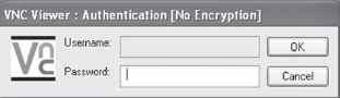
FIGURE 5-28
The VNC login block.
You will first need to configure a VNC password on your exciter. To do so, navigate to the Mode Control screen. Here, you will find a button that says Change VNC Password. Change the password to something you can easily remember. Note that this password will not be saved on the flash drive on which you saved the exciter’s configuration. If you upgrade the exciter’s software, you will need to reenter your password for VNC. The default password is “password.”
You will need to configure your Internet router to open ports 5810 and 5910 for TCP to the IP address of the exciter, in addition to port 80 if you intend to use the Java version of VNC. You only need to open port 5910 if you will be using the downloaded version of VNC exclusively.
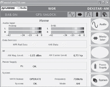
FIGURE 5-29
Using VNC is like sitting in front of the exciter.
If you have downloaded VNC to your computer, you would open VNC and connect to the Internet IP address at your exciter’s location followed by :5910. If my IP address at the transmitter site is 10.1.1.27, I would enter 10.1.1.27:5910 into the VNC connection screen. If I were going to use Internet Explorer to download the Java version of VNC from the exciter, I would enter into the address bar: http://10.1.1.27. A VNC splash screen appears, VNC loads from the exciter, and it will display the IP address of the exciter appended by :10; the exciter’s Java VNC assumes that the first two digits of the IP port number are 59. Clicking OK will make it ask for your password (see figure 5-28). Enter your password and you will be into the exciter.
Once you have logged in with VNC, it is almost the same as sitting in front of the exciter (see figure 5-29). Just be careful, as you can change something that might force a reboot, or you can change critical settings accidentally.
It is also possible to get into the exciter using ftp, telnet, and ssh. You will need to consult your exciter’s manual or manufacturer to set up and use these methods.
5.6.18 Software updates
Periodically, software updates become available for the HD Radio exciter. Your manufacturer will let you know when an update is available and what it does. Follow the directions that come with the update. Normally, you only need to reinput your VNC password, as the exciter configuration is saved on a flash drive. Some, like the upgrade to version 2.3.3 for the DexStar, required that the Magnitude/Phase Delay be reset, as the result of the upgrade was that the latency through the system changed. In general, most updates will completely rebuild the file structure of the exciter, in addition to updating the software. Follow the directions, reload your configuration from the flash drive, and you will be in good shape.
Note that updates are generally available via Internet download. The file you download is an .iso file. It is an image of the exciter’s hard drive. You will need to have a CD burning program that can correctly burn an .iso file, as the machine will need to boot from this CD-ROM.
5.6.19 Listening tests and maintenance
Once you have set everything up, and the transmitter is stable, you will want to take a test drive if you have an HD Radio receiver in the car. You should have a good sounding HD Radio signal and, if you took the time to properly set up the system, you should have digital coverage out to just beyond the station’s one millivolt per meter contour.
Maintenance of the HD Radio system is fairly basic. As with a transmitter, there are numerous “readings” that you should log periodically. I also perform a planned exciter reboot three times per year, with the thought that the exciter is a computer. Memory in computers sometimes, for no apparent reason, may become corrupted. Periodic reboots will generally prevent trouble from happening.
Some versions of the Moseley Starlink 950-MHz STL system did not properly set the “audio” bit in the AES-3 audio data stream. Additionally, the AES-3 protocol uses an “emphasis” bit. Older Moseley units not having the audio bit set and having the emphasis bit set could cause audio drop outs or complete muting of the AES-3 audio data from the studio.
Newer Moseley Starlink units do not exhibit this problem.
If you have an older Moseley Starlink unit, you may wish to contact Moseley regarding the fix for these issues. The fix is fairly simple to implement and involves either the setting of dip switches or the bridging of solder pads.
The Harris Premiere Web site has an easy field modification for the Moseley Starlink that will solve this issue. Log into the Harris Premiere Web site and perform a search for “Moseley”.
Analog FM radio has, for a long time, had the ability to send certain PAD to listener’s radio, such as title and artist of the song currently playing. This is accomplished through an RDS data subcarrier of 57 kHz injected along with the transmitted stereo baseband. The radio would interpret the data sent on the RDS 57-kHz subcarrier, and display title and artist information on the listener’s radio (if it was RDS-equipped).
With the AM HD Radio system, AM stations for the first time have the ability to send title and artist information, along with several other fields, to listener’s radio. It is a good idea for a station to utilize PAD. It will give radio manufacturers incentive to make sure this feature is included in future radio models, and it helps AM radio to be more competitive with FM and satellite radio because they also provide PAD.
The fields available for PAD are Title, Artist, Album, Genre, Comment, Commercial, and Reference Identifier. The PAD fields can be defined as such:
![]() TITLE – Song title or other program information.
TITLE – Song title or other program information.
![]() ARTIST – Song artist or other program information.
ARTIST – Song artist or other program information.
![]() ALBUM – Album the song can be found on or other program information.
ALBUM – Album the song can be found on or other program information.
![]() GENRE – Information about the type of program.
GENRE – Information about the type of program.
![]() COMMENT – A short description or comment on program content.
COMMENT – A short description or comment on program content.
![]() COMMERCIAL – This can include various information, such as price and seller name, and can be used to transmit a picture.
COMMERCIAL – This can include various information, such as price and seller name, and can be used to transmit a picture.
![]() REFERENCE IDENTIFIER – An identifier used for the owner of the material.
REFERENCE IDENTIFIER – An identifier used for the owner of the material.
PAD is derived from and defined in the ID3 tag specifications that are contained in the header of most music cuts on CD or on your automation system. More information on ID3 data can be found at http://www.id3.org.
It is most common to send the Title and Artist information fields. While this is obvious for music stations, talk stations could send title of the program and either the host’s name or call-in number; sports stations could send the score of the game. There are numerous uses of Title and Artist data.
Many digital automation systems have add-on modules to send PAD into the HD Radio exciter. There are also stand-alone programs available that can send PAD information on a schedule.
PAD can reach the exciter for transmission in two ways. Most exciters will accept correctly formatted PAD on an available COM port. Data protocol is 1200 baud, no parity, 8 bits, 1 stop bit. The common method to send PAD to the exciter, however, is through TCP/IP connectivity.
PAD is sent to the exciter using TCP/IP port 10000. The exciter must have a static IP address and, if a firewall or Internet is involved, port 10000 must be opened to the exciter’s IP address.
5.9 Exciter settings and what they do
The following settings and adjustments are found on the Harris DexStar HD Radio exciter. Software settings are found in irss version 2.3.3 of the iBiquity Digital Corporation HD Radio operating software. Some of these settings may be called something slightly different on exciters from other manufacturers, but all should be present and perform in the same manner.
MAGNITUDE LEVEL ADJUST – Adjusts the level of the magnitude signal sent to the transmitter’s audio input. Usually located on the back of the exciter.
PHASE LEVEL ADJUST – Adjusts the level of the RF signal sent to the transmitter. Usually located on the back of the exciter or on the Digital UP Converter (DUC) card in the exciter.
BLEND CONTROL – Located on the Audio Setup screen. Sets a data flag that alerts the radio that it is OK to blend to the digital audio signal. Can be set to:
![]() Blend – Which tells the radio it is OK to blend from the analog audio to the digital audio.
Blend – Which tells the radio it is OK to blend from the analog audio to the digital audio.
![]() Disable Blend – The radio will not be allowed to blend to the digital audio, and the digital audio will not be accessible by the radio if the user attempts to force digital audio (may be indicated as “HD”) on.
Disable Blend – The radio will not be allowed to blend to the digital audio, and the digital audio will not be accessible by the radio if the user attempts to force digital audio (may be indicated as “HD”) on.
![]() Disable, but allow selection – The radio will not automatically blend to the digital audio, but the user can command the radio to do this.
Disable, but allow selection – The radio will not automatically blend to the digital audio, but the user can command the radio to do this.
DELAY ADJUSTMENT – Located on the Audio Setup screen. Sets the delay of the analog audio to match the delay of the digital audio to make a smooth blend.
RAMP CONTROL – Located on the Audio Setup screen. Allows the station to ramp into and out of time delay on the analog channel. Gives the station the ability to exit analog delay for programming such as live sporting events. In version 2.3.3 of the DexStar, the exciter is automatically set to disable blending during ramping or when the delay is fully out, but the listener can force his radio to the digital audio channel. Ramp in and Ramp out can be controlled by the station’s remote control system.
RAMP RATE – Located on the Audio Setup screen. Determines how fast the exciter will ramp into or out of time delay. One sample is added or subtracted from the audio as per the number listed.
MODE CONTROL – Located on the Mode Control screen. Determines which HD Radio operational mode the exciter will operate in.
VNC PASSWORD – Located on the Mode Control screen. Allows you to change the password for VNC connectivity.
I/Q SCALE FACTOR – Located on the Mode Control screen. Sets the level of the composite Magnitude signal prior to the last digital-to-analog converter so that it does not overflow. The correct setting for AM operation is 12000.
DIGITAL CARRIER ON/OFF – Located on the Mode Control screen. Shuts off or turns on the HD Radio subcarriers. Can be controlled by the station’s remote control system.
REMOTE CONTROL ON/OFF – Located on the Mode Control screen. Used to disable or enable remote control connections to the exciter.
MAGNITUDE/PHASE DELAY – Located on the AM System Setup screen. Used to time align the Magnitude and Phase signals through the transmitter. Can be set separately for day and night operation. Day/night selection can be controlled by the station’s remote control system.
ANALOG GAIN – Located on the AM System Setup screen. Used to set internal AM carrier modulation of exciter with output of audio processor set to – 3 dBFS.
MAG. CHANNEL DC OFFSET – Located on the AM System Setup screen. Used to null any DC offset voltage at the audio input to the transmitter.
PHASE Q SCALE FACTOR – Located on the AM System Setup screen. This should always be set to 1.
ANALOG AUDIO BW – Located on the AM System Setup screen. Sets the bandwidth mode of the exciter:
![]() 5 kHz – Enables the exciter’s internal 5-kHz brick-wall audio filter and tells the radio to operate in 5-kHz mode.
5 kHz – Enables the exciter’s internal 5-kHz brick-wall audio filter and tells the radio to operate in 5-kHz mode.
![]() 8 kHz – Enables the exciter’s internal 8-kHz brick-wall audio filter and tells the radio to operate in 8-kHz mode. Note that this audio filter is actually a 9-kHz filter as described in the NRSC-1-A standard. The original iBiquity Digital Corporation specification did include an 8-kHz filter.
8 kHz – Enables the exciter’s internal 8-kHz brick-wall audio filter and tells the radio to operate in 8-kHz mode. Note that this audio filter is actually a 9-kHz filter as described in the NRSC-1-A standard. The original iBiquity Digital Corporation specification did include an 8-kHz filter.
![]() BYPASS – Disables the exciter’s internal audio filtering, allowing 5-kHz audio filtering to be done in the audio processor. Tells the radio to operate in 5-kHz mode.
BYPASS – Disables the exciter’s internal audio filtering, allowing 5-kHz audio filtering to be done in the audio processor. Tells the radio to operate in 5-kHz mode.
ANALOG MODULATION ON/OFF – Located on the AM System Setup screen. Used during setup to turn the analog channel modulation on or off.
LOWER/UPPER SB LEVEL – Located on the AM System Setup screen. Allows fine level setting of the primary HD Radio subcarriers as viewed on a spectrum analyzer. Primary subcarriers should be set to –28 dBc.
ENH. CARRIER PWR LEVEL – Located on the AM System Setup screen. When switched to HIGH, it will increase HD Radio carrier levels by 6 dB.
SIDEBAND INDICATOR – Located on the AM System Setup screen. No longer used.
CARRIER FREQUENCY – Located on the Station ID screen. Sets station carrier frequency.
COUNTRY CODE – Located on the Station ID screen. Identifies the country of origin of your station. Should be set to 1 for broadcasters in the United States. Other countries should refer to ITU Operational Bulletin 763-1.V.2002 for information.
NETWORK ID – Located on the Station ID screen. Consult iBiquity Digital Corporation for this setting.
FACILITY ID – Located on the Station ID screen. Set to your FCC Facility ID.
LONG NAME – Located on the Station ID screen. The Long Name is displayed on some radios. Can be set to Corporate name, station slogan, or other wording.
CALL LETTERS – Located on the Station ID screen. Station call letters.
SONG ARTIST – Located on the Station ID screen. Part of the Internal PAD Generator of the exciter. Field should be blank to allow use of external PAD on listener’s radio.
SONG TITLE – Located on the Station ID screen. Part of the Internal PAD Generator of the exciter. Field should be blank to allow use of external PAD on listener’s radio.
GENRE – Located on the Station ID screen. Part of the Internal PAD Generator of the exciter. Field should be blank to allow use of external PAD on listener’s radio.
ALBUM – Located on the Station ID screen. Part of the Internal PAD Generator of the exciter. Field should be blank to allow use of external PAD on listener’s radio.
BIT ERROR RATE MODE – Located on the Exciter Diagnostics screen. Used to send a bit error detection pattern when used in conjunction with a test radio. Do not turn it on. The exciter will not send HD Radio digital audio when this is on.
SINGLE SUBCARRIER MODE – Located on the Exciter Diagnostics screen. Used to send only one HD Radio subcarrier at a time for testing purposes.
EXCITER TEST SCREEN – These buttons and functions are used for specific diagnostic purposes, and should only be used when troubleshooting with factory representatives.
HOSTNAME – Located on the Network Configuration screen. Allows setting of a host name, known as a computer name in Microsoft Windows. Do not put a space in the host name. The exciter may get stuck in a boot up loop and need to be returned to the factory.
DOMAIN – Located on the Network Configuration screen. Used to set the domain name, if any, of the network to which the exciter will be attached.
IP ADDRESS – Located on the Network Configuration screen. Allows setting a static IP address for the exciter.
NET MASK – Located on the Network Configuration screen. Allows setting of the network mask for the exciter’s network connection.
DEFAULT GATEWAY – Located on the Network Configuration screen. Allows setting of the Internet Gateway for IP Exciter access across the Internet.
NETWORK CONFIGURATION – Located on the Network Configuration screen.
![]() Off Net – Points the exciter to a default IP address and tells the exciter it is not connected to a computer network.
Off Net – Points the exciter to a default IP address and tells the exciter it is not connected to a computer network.
![]() DHCP – Allows the exciter’s network IP address, Net Mask, and Gateway to be configured by the station’s DHCP server.
DHCP – Allows the exciter’s network IP address, Net Mask, and Gateway to be configured by the station’s DHCP server.
![]() Static IP – Allows the exciter’s IP address to be set.
Static IP – Allows the exciter’s IP address to be set.
![]() Save Cfg. – Saves network configuration. Exciter will need to reboot after configuration is changed.
Save Cfg. – Saves network configuration. Exciter will need to reboot after configuration is changed.
GPS CONFIGURATION SCREEN – Shows GPS parameters and allows setting of certain parameters:
![]() ANTENNA DELAY (in nanoseconds) – This should be set as per a chart found in the exciter manual, and this is based on type and length of GPS antenna cable.
ANTENNA DELAY (in nanoseconds) – This should be set as per a chart found in the exciter manual, and this is based on type and length of GPS antenna cable.
![]() TIME ZONE – Set for the time zone of your station.
TIME ZONE – Set for the time zone of your station.
![]() DAYLIGHT SAVING TIME – Check the box if your station’s area observes Daylight Saving Time.
DAYLIGHT SAVING TIME – Check the box if your station’s area observes Daylight Saving Time.
STATION SCHEDULER SCREEN – For future use, it will allow stations to dictate which parameters, such as call letters, time, and long station name, will be sent to radios in what order.
FAULT LOG – Will display any faults in the exciter. Note that the log will clear if the exciter reboots. The data is not saved.
EXCITER UPGRADE SCREEN – Allows saving of exciter configuration and upgrading of exciter software. Should be used with instructions from the manufacturer of the exciter for upgrading.
TOUCH SCREEN CALIBRATION – Everyone’s eyes see slightly differently. This screen allows you to set where you think the center of a target is, and will make for easier touch screen operation.