
Audio Processing for HD Radio
4
4.1 What an audio codec is and how it works
In the previous chapters, we have stated that the digital audio on an HD Radio signal is data-reduced audio. Due to the constraints of the assigned channels on AM and FM stations, a non-data-reduced signal would be far too large to transmit. An audio codec is therefore used to remedy this situation.
An audio codec has two parts: an enCOder on the transmit side, and a DECoder on the receive side. These work in tandem to pass the audio from the transmitter through the RF channel and into the listener’s receiver.
Unfortunately, I cannot give details about how the HDC codec used in the iBiquity Digital HD Radio system actually works. This information is proprietary and iBiquity would not release details for publication. I have been told, however, that the HDC codec has been optimized for data rates between 32 and 96 kbps. I will therefore submit a general overview of how codecs operate.
All perceptual audio codecs are based on a computer model of the human ear and on how humans perceive audio (hence the term “perceptual”; in the context of this discussion “perceptual audio codec” and “audio codec” are synonymous). The idea is to produce an algorithm that will, based upon our knowledge of human hearing, be able to remove parts of the audio that the ear normally would not “hear” under normal listening conditions.
To get this concept in mind, think for a moment about the human eye. It is easily tricked. At the movie theater, your eye will tell you that the characters are moving across the screen fluidly when in actuality, there are 24 still pictures being flashed on the screen in any given second. The pictures are changed so rapidly that the eye cannot perceive that they are individual pictures. The eye perceives the scene as having movement. It is the same idea with analog television, where an electron beam scans across the face of a cathode ray tube, drawing 30 pictures per second. Your eye does not pick up on the scan lines or the changing pictures, but registers all the above as smooth motion.
The human ear can be tricked, as well. One example of this is the Arbitron portable people meter (PPM) system. It operates under the theory that the ear cannot hear one tone if it is placed next to another tone at a much higher level. The PPM system analyzes the incoming audio, then places its data into the audio in a series of brief tones, right next to and at a lower level than the normal audio. Your ear does not have the ability to pick out these bursts of data, and the listener is blissfully ignorant of the fact that the PPM data is being added to the audio.
The algorithm created for a given codec analyzes the incoming audio; determines, based on its knowledge of human hearing, what sounds the ear will not be able to notice are missing; and removes these sounds. In the case of HD Radio audio coding, the incoming audio is linear and sampled at 44,100 times per second. The data rate of the incoming AES-3 signal is:
44,100 samples/second × 16 bits/sample × 2 audio channels
making the data rate 1,411,200 bits per second (bps).
The HD Radio codec output data rate for the AM HD Radio system is 32,000 bps (alternatively expressed as 32 kbps). The codec is a busy beaver as it has to reduce this data stream by a ratio of 44:1. That’s a lot of data to remove! On the FM HD Radio system, if your primary FM HD Radio digital-audio channel is running at 96 kbps, the reduction ratio is 15:1. At 64 kbps, it is 22:1. This is important to keep in mind as we go further into processing, and you will understand why I have stated previously that there are things a station can get away with in the analog domain that simply will not work in the HD Radio digital audio domain.
This is why I have also stated previously that your source audio, as delivered to the HDC codec, should be as clean as possible. Dirty audio can translate to really bad audio in the HD Radio digital audio domain, as the codec may remove good sounds and leave the bad ones in. As Cris Alexander, Director of Engineering of Crawford Broadcasting was so eloquently quoted in an article in Radio World Magazine, “You can make AM HD-R sound truly FM-like with good attention to details: proper load symmetry/orientation, low-compression/high data rate source material, high-bandwidth/low-compression or linear STL and careful processing. You can otherwise, with very little effort, make it sound really bad.”
The codec will work on the audio and remove what it knows the ear cannot hear. It will then package this data, along with instructions for the decoder side of the codec, and ship it off for transmission. The instructions tell the decoder how to reconstruct the audio waveform, and also includes information so that the decoder can reconstruct data that may be missing in the form of lost packets.
In the radio, the HD Radio signal is demodulated, and the codec is presented with the data packets from the encoder side. The decoder must take the data it has been presented, look at the instructions, and reconstruct the original audio waveform as best as possible. If done properly, the human ear will not be able to tell the difference between the reconstruction and the original. If, however, there are data packets missing, or the source audio was bad to begin with, the listener will hear coding artifacts. If data packets are missing, the codec will look at the data presented before the lost packet(s) and the data presented after the lost packet(s), and reconstruct the missing data depending on its interpretation of what is missing.
In Chapters 3 and 4, I have discussed why it is important that your source audio be linear or, if it must be data reduced, to use the least amount of data reduction possible. Let us first consider the linear source. We will discuss putting the audio through the AM HDC codec.
The linear source will be presenting a data rate of 1,411,200 bps to the encoder. The encoder, in turn, is reducing this to 32,000 bps for the AM HD Radio system. Since it is the original audio that is being reduced, it will sound extremely good (as good as it can, using this codec) at the output of the decoder.
Now let us take a look at a data-reduced source. Your automation system has been presented with a linear source of 1,411,200 bps. If you are reducing it to 192,000 bps, you are reducing it by a ratio of 7.5:1. This audio will sound quite good.
Now you will take this data-reduced signal and put it through the AM HDC codec. You are putting a signal with 192,000 bps in, and in the case of the AM HDC codec, getting 32,000 bps out. Initially, you will think that the HDC codec is getting off easy, and technically it is. Reducing a 192 kbps signal is a far cry from reducing a 1411.2 kbps signal. But consider that you have already thrown out an awful lot of data from the original signal. The waveform as presented to the HDC codec is already missing parts. The HDC codec will now further reduce what it has been presented with. It may make some errors in its interpretation, because the information it is working with already has missing parts. This will likely cause audible artifacts in the output of the codec in the listener’s radio. In many cases, the artifacts are not bad, and the average listener will not hear them. In some cases, however, the artifacts are extremely audible.
On remotes, we tend to run the ISDN codecs at WOR with the AAC audio-coding algorithm. We had been using MP3. We found that, with the MP3 algorithm running at the maximum ISDN rate of 64 kbps, the audio on the HD Radio channel had a peculiar “ringing” to it, almost like an audible halo. You will need to experiment to find what works best for your station.
My best guess is that the HDC codec being used by iBiquity in the HD Radio system is somewhat similar to AAC. I make this statement because I find that, if I must use data-reduced audio files, AAC coded files sound best going through the HDC codec. If you experiment with various audio codecs, you will find that further data reduction within the same type of codec will present fewer artifacts than if you have switched codec types. Experimenting off-line with digital editors, I find that I can come very close to the sound of the HDC codec if I use the AAC algorithm.
If you are not familiar with codecs and how they work, I would suggest that you sit down with an audio editing program and experiment. Record an audio source in linear mode; convert it to a data-reduced format, like MP3 or AAC; and see what it sounds like at various data rates. Take one of your conversions and save it. Open it again with the editor, and save it at a lower data rate and/or as another type of codec at a lower data rate. Compare the data-reduced files with the original audio and hear what happens. You will soon discover and begin to understand what happens as you cascade algorithms and data rates. It is a good method to understand how to feed the HDC codec.
4.2 Processing the analog and digital audio separately
As part of the process of installing the HD Radio system at your station, you will need to do the audio processing of the HD Radio digital audio separately from that of the analog audio. For AM HD Radio systems, one obvious reason for this is the frequency response difference.
The digital audio portion of the AM HD Radio signal has an upper frequency response limit of 15 kHz. The AM analog signal prior to the installation of the HD Radio system had an upper frequency response limit of 10 kHz (in accordance with the NRSC-1 standard). With the HD Radio signal, this will be reduced to 5 kHz, unless you choose to use the 8 kHz option for AM HD Radio transmission.
On the analog processor, you first need to roll off the high frequency response at 5 kHz. You then need to make equalization adjustments that will add some life to your 5 kHz frequency limited audio. If you do not tweak the equalization, the signal will sound very dull and muddy.
You will most likely be running a decent amount of compression on the analog audio, and will be hard clipping the output, in addition to running asymmetrical audio with positive peaks exceeding 100 percent modulation. Incidentally, regardless of what you may have heard, you may run up to 97 percent negative peaks and up to 125 percent positive peaks on the analog signal when you turn on your HD Radio signal.
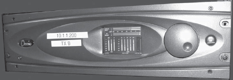
FIGURE 4-1
The Omnia 5-EX AM audio processor. This processor has outputs for both the analog audio channel and the digital audio channel. It allows completely different settings for both the analog and digital sides.
On the HD Radio digital audio side, you will have an upper frequency response limit of 15 kHz – considerably higher than the upper response limit on the analog side. The digital audio will be stereo, as opposed to mono on the analog side. The equalization points are purposely different on the digital audio side for better performance through the HDC codec. And you will not use hard clipping at all on the digital audio side. Most audio processors used on the digital audio side use various “look ahead” methods to pull down the peaks so that they do not become an overmodulation issue rather than hard clipping them.
When you hard clip an audio peak, two things happen. First, the top of the waveform gets clipped off, and in most cases, this prevents overmodulation and can also make the signal louder. Clipping, however, introduces distortion to the waveform and will generate harmonics that did not exist in the original audio.
If you think about the section on how codecs work, you know that the codec looks at the audio waveform and determines, based on its knowledge of human hearing, what audio to remove that the ear cannot hear. The codec will first of all have a difficult time reproducing the clipped part of the waveform. Secondly, the clipping produces harmonics. If the codec is to make a decision on what audio to remove, it can very easily accidentally remove the audio that should remain in the waveform rather than removing the harmonics generated by clipping. This results in unexpected audio artifacts, usually unpleasant. This is why it is important not to hard clip the audio on the HD Radio digital audio channels.
One mistake stations make, particularly FM stations because the digital audio is very close to the sound of the analog audio, is that they attempt to process the digital audio exactly as the analog. The purpose of HD Radio technology is to give the listener a better experience. If your analog signal is already over processed, it will serve no purpose to over process the HD Radio digital audio channel. A little processing goes a long way on the digital audio. The codec will have a difficult time data reducing heavily processed audio, and it may result in unintended consequences. Make no mistake: audio processing, while one of the tools radio stations use to attract listeners, is technically distorting the audio. Start your processing adjustments with small amounts of processing, and gradually increase. You will find that a small change in, say, compression levels will result in a large change in the sound of the HD Radio digital audio.
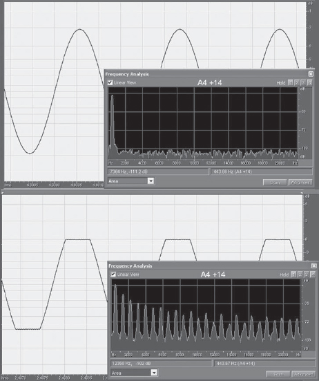
FIGURE 4-2
The effects of clipping on the spectral content of an audio signal. The audio sine wave is a 400-Hz tone. In the top screen shot, notice the spectral content in the lower right-hand corner. You can see the fundamental frequency. Anything else is in the noise floor. In the bottom screen shot, the sine wave was clipped five decibels. Note the significant harmonics generated by this clipping action. The perceptual codec may accidentally mistake these harmonics for valid audio, removing audio that is relevant, thus causing unpleasant artifacts. This is the reason clipping on the digital audio should be avoided.
For FM stations, the analog audio will be frequency limited to 15 kHz, processed and pre-emphasized, clipped, and then passed through a stereo generator. The digital audio, on the other hand, has an upper frequency limit of 20 kHz, will be processed, soft limited, and passed through the HDC codec. Both audio paths are extremely different from one another. If you try to set the processing on the digital side as it is set on the analog side, the digital audio will sound pretty raunchy.
When you achieve the sound you are looking for, you will need to make sure that the delay is adjusted correctly so that, when the HD Radio receiver blends, the transition is smooth and not disjointed. There are several methods to do this, one involving simply splitting the audio so that the analog audio is on one channel and the digital audio is on the other channel, and listening carefully with a pair of headphones. Another method involves recording a small portion of the audio on a digital editor using an HD Radio receiver to split the channels. You can then determine, by looking at the received analog and digital audio waveforms on the editor, how much your delay is off in nanoseconds and adjust accordingly.
You also want to balance the audio levels between the analog and digital channels. First, set up your analog modulation so that it is legal and where you want it to be. Then listen to the audio in split channel mode, and adjust the digital audio level. You want to bring the digital audio level to that of the analog audio. You do not want to adjust the analog level once you have set it. Once you think you have the levels set correctly, let the radio blend as it normally would. You should hear very little difference in level between the analog and digital audio if you have the levels set correctly.
Experiment with your new processor. You may be quite surprised to discover how much loudness you can get on an HD Radio digital-audio channel without over processing the audio and without using clipping. You will also need to get used to not hearing your adjustments in real time! Don’t forget, there is greater than an eight-second delay on both AM and FM HD Radio systems. If you are like me, you will need to learn the virtues of patience with processing adjustments in the HD Radio world.
The HD Radio equipment will need an AES-3 signal as its input. The processors, however, give you an option to feed them from an analog source or an AES-3 source. Many of the processors have an automatic failover selection so that if the AES-3 input fails, it will default to the analog input.
If your studio and STL system can give you an AES-3 signal, by all means use it. If you are going to use analog signals to feed the processor, you may wish to use an A-to-D converter to convert these to AES-3 signals. The reason for this is that I have seen a processor fail and shut down its AES-3 outputs after a power bump because it did not have an AES-3 clocking signal available to it. Converting your analog audio to AES-3 will present your processor with this clocking signal and help prevent mishaps like this.
Some manufacturers make processors that combine the analog channel processing and the HD Radio digital audio processing into one chassis. I use an Omnia 5-EX on WOR with excellent results. There are also separate processors made for analog and digital. The choice is yours. Some feel that using an “all in one” processor is putting all of one’s eggs into one basket and consequently not the best approach.
While it may sound odd to have both the analog and digital audio channels processed in the same chassis, there is not much common to both audio chains. Normally, the audio is input to the processor and enters an automatic gain control (AGC) circuit. From here, the audio usually separates into the analog side and the digital side. The “all in one” processors work extremely well.
If you intend on keeping your present analog processor for the analog channel, you will need to feed its output to the HD Radio equipment as an AES-3 signal. Contact the manufacturer of your processor regarding obtaining the AES-3 option. Alternately, you can use an external A-to-D converter.
Keep in mind that the newer audio processors, especially the processors used on the HD Radio digital audio channel, are computers. It is wise to put the audio processors on an uninterruptible power supply (UPS). In this way, a momentary power failure will not cause you to be off the air waiting for the audio processor to reboot.
There are several ways to implement and control the delay of the analog audio channel. One is to simply let the HD Radio exciter or Exporter add the necessary delay. This, actually, is the most common option with AM HD Radio, though at least one processor manufacturer now gives you the ability to let the processor do this.
Most of the FM HD Radio processors that are “all in one” processors can produce the delay for the analog channel. This, in my opinion, is the preferred choice, since if you are using the HD Radio Exporter to create the required delay in the analog channel and the Exporter fails, your analog channel fails, too. In other words, using the audio processor to create the delay protects the analog channel from Exporter failure. The audio processors are very stable and can easily handle this chore.
A third method would be to use an external delay unit on the analog AES-3 signal to the transmitter. Eventide makes an excellent unit that can be adjusted to nanoseconds and will easily produce the analog channel delay for you. Of course, using this method, you may have one more thing to reboot in the event of failure. But the choice is yours.
4.5 Where, physically, does the processor go?
There are many schools of thought as to where the audio processor should physically be. With AM HD Radio, as of the writing of this book, the processor really must go at the transmitter site, unless you have two AES-3 audio channels between the studio and transmitter site. Putting the processor at the transmitter site simplifies adjustments for modulation but, of course, complicates matters for audio adjustments.
With FM HD Radio, the processor should be where the Exporter is. If your Exporter is located at the studio, the processor should be at the studio with it. My personal preference is to put the Exporter at the studio. As of this writing, the Exporter runs under the Microsoft Windows operating system. At some point, it will need to be rebooted, and this will happen at a most inopportune time. Having the Exporter at the studio makes it easy to reboot, and makes it easy to control or make changes to should the need arise.
If you are doing the FM analog audio delay in the audio processor or with an external delay device, the analog AES-3 signal feeds directly into the digital STL. At the transmitter site, the AES-3 signal of the analog audio feeds the exciter directly. The HD Radio AES-3 signal feeds the Exporter. The Exporter feeds the digital STL via Ethernet connection.
If you are doing the analog audio delay in the Exporter, the analog AES-3 signal from the audio processor is input to the Exporter, and the analog AES-3 output of the Exporter feeds the STL.
We will discuss the HD Radio equipment involved and how to connect it in a later chapter.