
3. Pattern Instance Notation
Before we explore the impact of what we can do with Elemental Design Patterns (EDPs), I want to take a bit of a side jaunt and introduce a new graphical notation, the Pattern Instance Notation, or PIN. PIN is used from here out to help you visualize some of the concepts we discuss.
This chapter provides an informal description of PIN and how it is used in this book. If you’re interested in further information or in how PIN can be used in tool support for software design, PIN is fully described in “The Pattern Instance Notation: A Simple Hierarchical Visual Notation for the Dynamic Visualization and Comprehension of Software Patterns” [36].
3.1. Basics
PIN is a visual representation of the concepts and ideas that comprise patterns. It is intended as a quick and easy way to document and describe design patterns and their interactions. The name PIN was chosen because it also is useful in showing instances of patterns or concepts in other diagramming notations, such as UML. This was the original use case.
In Chapter 2, Section 2.2.2, I mentioned the Participants section of a design pattern specification. Participants are the parts of a design pattern that must exist for an instance of the design pattern to occur. Another name for them are the roles of the design pattern, because each participant has a particular role to play in bringing together the pattern. In other words, each participant fulfills a role of the pattern. When we say “the participant named ConcreteDecorator of the Decorator pattern,” what we really mean is “the class of the implementation that fulfills the ConcreteDecorator role of the Decorator pattern.” The roles are abstractions as well, because they provide a name for, and constraints on, the implementation or design features that will act as participants.
It’s not unlike a play, such as Hamlet. Hamlet is a role, as are Ophelia, Rosen-crantz, and Guildenstern. They describe a part and provide guidelines for the kind of actor who will be cast in each role. The actor is a participant in the stage production, and all the actors collaborate to form it.
The play is analogous to a design pattern, and the particular stage production is an instance of the pattern. The script is like the design pattern specification: it describes roles, and it describes how they communicate and interact. The actors who are cast in those roles are the participants.
UML has a graphical feature, the collaboration element, to describe such situations. An example using Decorator is shown in Figure 3.1. This isn’t a bad notation by any means, and it is very flexible, but it suffers from a couple of problems for our needs. For one thing, it is a bit messy in practical use at anything other than in trivial diagrams. It only adds information to a UML diagram. The more you use it, the more complex the diagram becomes. Abstractions such as design patterns are intended to reduce complexity and detail by letting us operate at a higher level of abstraction. A sticking point of UML collaborations is that they aren’t capable of reducing the complexity in a UML diagram. They can’t reduce the amount of exposed information as a higher level of abstraction should. A collaboration element also requires a complete UML diagram to be placed in, in the first place. This may seem like an odd complaint when we’re discussing a UML feature, but it turns out that there are plenty of situations where we may want to discuss how patterns interact without having to create a diagram for all the pieces necessary to implement them.
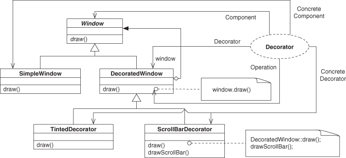
Figure 3.1. UML collaboration diagram.
Another common notation for design patterns is the pattern:role notation introduced by the Gang of Four (GoF) [21]. It is also an annotation to be used on top of UML, and it uses an external flag that is named with the pattern and the role. This annotation can be applied to a class, package, field, or method as needed, as shown in Figure 3.2. It’s very flexible and obvious, but it isn’t without issues.
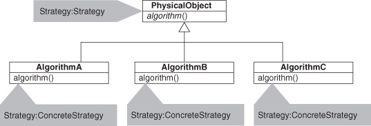
Figure 3.2. Strategy as pattern:role tags in UML.
This approach isn’t so bad when only one pattern is involved and displayed, but what happens when you have a pattern hidden in a diagram with hundreds or even thousands of pieces? Say, something like in Figure 3.3?
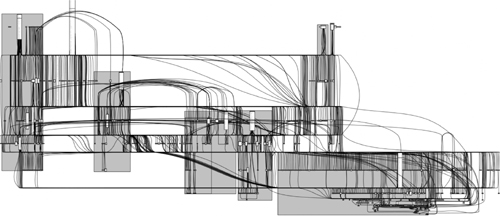
Figure 3.3. Huge UML of a not-so-huge system.
Figure 3.3 is an actual UML diagram from an actual project. It’s unreadable at this scale, but practically speaking, it’s almost unreadable at any scale. If you were to print it at actual dimensions, such that the type was 10-point size, it would be 86 by 32 feet. That’s a lot of paper: 3,290 standard U.S. letter-size sheets. At this size, it’s too small to be read, but at the full size, it’s too large to be searched visually. Frustratingly, a wealth of patterns are recorded in the diagram, ready to be found and learned from to help document the system.
As a more concrete example, consider a UML diagram such as in Figure 3.4. There are two instances of the Strategy pattern in Figure 3.4, but using the pattern:role notation, we can’t tell which pieces go with which pattern instance, even in this small example.
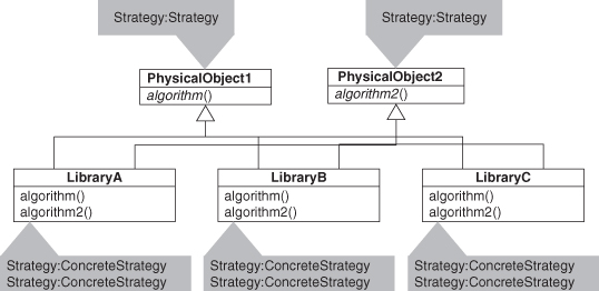
Figure 3.4. Multiple instances of Strategy as pattern:role tags in UML.
This was the initial reason for the PIN: to be able to clearly express multiple instances of patterns in a single diagram as first-class entities. Hence the name, Pattern Instance Notation. Other goals are that the notation be simple, flexible, and usable in conjunction with other notations such as UML without being reliant on them.
3.2. The PINbox
The core notation in PIN is the PINbox. It represents a single pattern instance and lets you choose the level of granularity you want to expose. We start with a PINbox in its simplest form and work our way up into more interesting variants.
3.2.1. Collapsed PINbox
The collapsed PINbox is just a name label with a thick double border, as in Figure 3.5. The interior border stroke is a rectangle, the external border stroke has curved corners. If possible, the border is shaded gray. The label on the box is the name of the pattern.
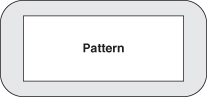
Figure 3.5. Collapsed PINbox.
That’s it. That’s the simplest form of a PINbox. Don’t worry, there’s more to come. Even here, though, we have something useful to work with. We can use this as an annotation onto a UML or other diagram by just drawing an arrow from the PINbox to whatever element in the diagram is most closely associated with it, as in Figure 3.6. When it comes to graphical notations, experience shows that boxes and lines are about as simple as it gets.
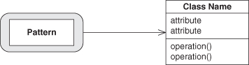
Figure 3.6. Collapsed PINbox as annotation.
For some examples of how this might work in real life, consider Figures 3.7 and 3.8. The example using Singleton and Abstract Factory shows PIN being used with a class diagram, while Template Method indicates a pattern in a sequence diagram.
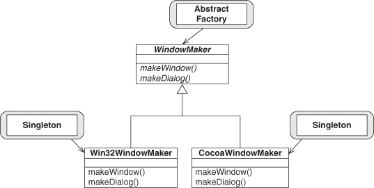
Figure 3.7. Singleton and Abstract Factory in class diagram.
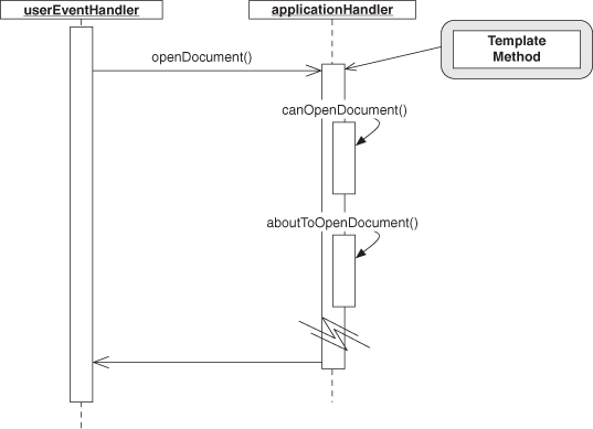
Figure 3.8. Template Method in sequence diagram.
The collapsed PINbox is best used when you need a mnemonic, a quick reminder that a pattern exists in a system, and the pattern is one that has a single, defining feature you can point to. This is an informal notation but one that has utility, particularly when sketching out a new design.
3.2.2. Standard PINbox
Taking things up a level, we have the standard PINbox. We expand the thick gray border of the collapsed form so that we can add text to it. Specifically, we add the roles that make up the pattern listed in the middle, as in Figure 3.9. The roles are named using the same conventions outlined in Chapter 2, Section 2.2.1. Adding the roles lets us express some significantly finer-grained connections. For instance, because each pattern has a well-formed and distinct set of these roles, we can connect each role to the elements of a UML class or sequence diagram, as in Figures 3.10 and 3.11.
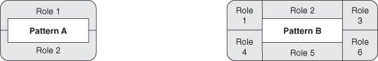
Figure 3.9. Standard PINbox.
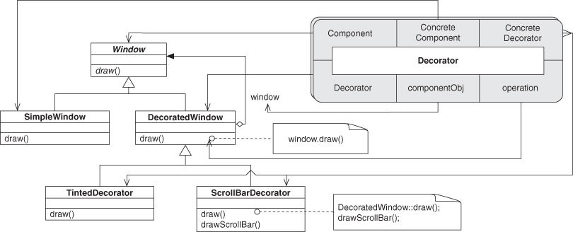
Figure 3.10. PIN used with UML class diagram.
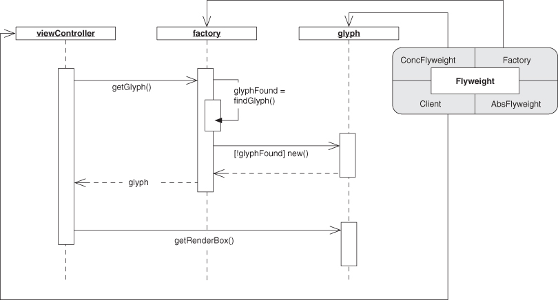
Figure 3.11. PIN used with UML sequence diagram.
The arrangement of the role names around the border is up to you; however it looks best on the final diagram is fine. Whatever ordering makes the final diagram easiest to read is preferred.
This looks an awful lot like a UML collaboration from Figure 3.1, but PINboxes can do some things that collaborations can’t. Note that in Figure 3.11, the instance of Flyweight has the AbsFlyweight role not attached to anything. This is fine in this case because we’re just trying to depict the interactions between the other three roles. If we tried this with a collaboration element and wanted to retain all of the information about the roles of the Flyweight pattern, we’d either have to have a dangling arrow with the unused role name or, worse, not show it at all. Neither is optimal. With the PINbox, we don’t lose the information, and we don’t clutter up our diagram needlessly. For another example, say we have two pattern instances in a software design and we want to indicate that the same class that fulfills a role in one fulfills a role in another, tying the two pattern instances into a combined structure. We could do this as in Figure 3.12. Notice that this diagram doesn’t use any UML; it only shows the connection between two patterns in a particular way. Things get much more interesting when we connect multiple PINboxes together.
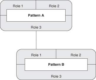
Figure 3.12. Standard PIN role connections.
There is no UML.
There is no code.
There are no classes, methods, fields, no anything, just a relationship between two patterns, two concepts, and that relationship ties them together in a particular way. We use this capability to show how patterns can be combined into new concepts in the next chapter.
We can do still more, though.
3.2.3. Expanded PINbox
If we make a small tweak to the PINbox, it becomes much more flexible and powerful. Let’s start by expanding the box in the center, the one that currently just holds the pattern name. We end up with something that looks like Figure 3.13. Now we can use this new blank area to draw additional PINboxes. Why would we want to do this? Well, look at Figure 3.14. Here we’ve filled in the canvas. What this shows is that Pattern has five roles and can be decomposed into two smaller subpatterns: Subpattern A and Subpattern B. Further, it shows exactly how the roles on the outside ring map to the roles of the inner subpatterns. If we have Subpattern A and Subpattern B, such that Role 3 in Subpattern A is fulfilled by the same entity in a system as Role 1 from Subpattern B, then we could replace those two instances with a single instance of Pattern. In other words, we could raise the level of abstraction a bit. Instead of having to keep track of two things, we only have to manage one pattern instance.
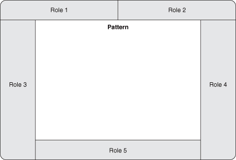
Figure 3.13. Blank expanded PIN instance.
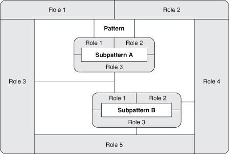
Figure 3.14. Expanded PIN instance.
On the other hand, if we had an instance of Pattern, it’s clear that we also have an instance of each of the subpatterns. They may be buried a bit, but we know they have to be there.
The expanded PINbox lets us reveal the hierarchical nature of patterns to whatever degree we wish. We can leave a single pattern at the highest level of abstraction, or we can keep expanding it to show more detail. Also, as shown in Figure 3.15, we are not limited to using just the PIN on this canvas. We can integrate UML or some other notation to illustrate a particular point. In the case of EDPs, which cannot be decomposed into smaller subpatterns, the ability to display UML offers a direct definition instead. Alternatively, we may want to place the UML diagram that demonstrates one implementation of, say, the Decorator pattern, inside the PINbox. This could be used as a reference illustration for a student or as a quick reminder in a design support tool. Flexibility is what makes PIN so uniquely useful for depicting the definition and composition of patterns.
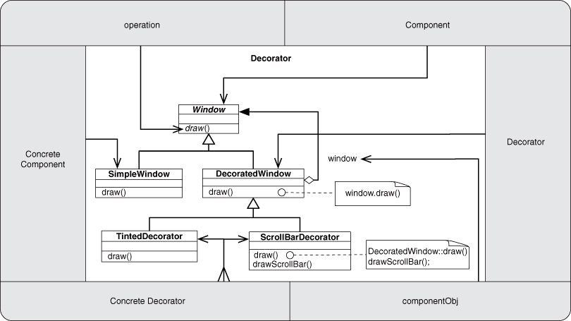
Figure 3.15. Expanded PIN instance using UML.
3.2.4. Stacked PINboxes and Multiplicity
Many patterns have a multiplicity to their elements. Generally, more than one participant fulfills the Concrete Decorator role in a Decorator pattern, for instance, and Abstract Factory loses much of its usefulness if there is only one kind of factory. Using a strict interpretation of the PINbox definition, we’d have to use one PINbox for each combination of the elements. Look at the basic Abstract Factory diagram in Figure 3.16. To properly annotate it with standard PINboxes, we’d need four: one for each Concrete Factory times each Concrete Product. And we’re only discussing two factories and two products right now. Imagine if there were, say, four factories and 10 products. Forty PINboxes would be impossible to navigate and horrendously confusing. And we would but we also want to make sure that someone looking at the diagram knows that these individual pattern instances are simply parts of the same pattern instance at a higher level, that they are fundamentally connected. We can show the relationships by using a stacked PINbox, as in Figure 3.17.
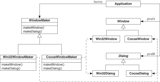
Figure 3.16. A need for multiple related PINboxes.
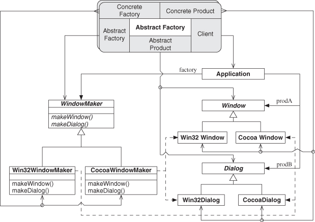
Figure 3.17. Stacked PINbox.
We added a second outline “behind” the PINbox to give the appearance of PINboxes stacked like a deck of cards. Also, notice that we changed the arrows coming from the Concrete Factory, Concrete Product, and Abstract Product roles. The tail now has a forked appearance to indicate that there are multiple connections, and then the line splits to point to each of the entities that previously would have been indicated by a unique PINbox. To help illustrate where the splits occur, a small circle is added at the junction points. Junction points that lack this indicator are where multiple roles are satisfied by the same element, as before.
In general, multiplicity connections should be used with care with PINboxes. Remember our goal is simplicity, and if two roles have multiplicities associated with them, we have to be extremely clear that the relationship is properly defined by the abstraction we are denoting. In this case, having three roles with multiplicity makes sense. Each Concrete Factory must handle each of the Concrete Products, and the Abstract Products are clearly linked with their corresponding concrete subclasses. It’s hard to get confused in this case.
If, however, there were multiple Abstract Factory entities, each would necessitate the creation of a new stacked PINbox instance. Think of it this way: if a pattern lends itself well to use as a collapsed PINbox, then it likely will be useful as a stacked PINbox with several multiplicities, if and only if the role that makes it useful in the collapsed form is not associated in a multiplicity. In other words, if there is one role that is so prominent that it can be used in the collapsed form successfully, then it can be used as the linchpin role for a stacked PINbox.
Building on this, Figure 3.18 revisits the situation from Figure 3.4, where we had multiple instances of Strategy but couldn’t reliably distinguish between them. Now we have two Strategy clusters, and each is distinct and clearly discernable. We use the stacked form to indicate that there are multiple concrete strategies for each pattern instance. This is useful, certainly, but what if we wanted to capture the very idea that we are using multiple clusters of Strategy in concert?—not a single Strategy, but more than one, acting together. In other words, what if we decided that this multiple Strategy situation was common enough that we wanted to tell someone else about it, clearly and cleanly. In such a case, we might use Figure 3.19 to explain it. We stripped out the UML, the portion that corresponds most closely to our implementation, and we abstracted out the connection between the Strategy clusters into something simple and precise. This diagram is much simpler than our original in Figure 3.4 and provides a mechanism for faster sharing and clearer communication of what we are trying to get across: “There is more than one Strategy at work here, and the same classes are acting as concrete strategies for each.” This could even be the seed of a new design pattern writeup.
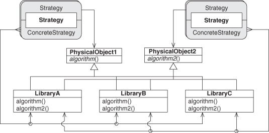
Figure 3.18. Multiple Strategy instances as PINboxes.
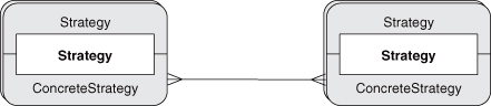
Figure 3.19. Showing the interaction between multiple Strategy PINboxes.
3.2.5. Peeling and Coalescing
There’s one last trick of the expanded PINbox that is useful to know about, even though we don’t use it extensively in this book. Recall that in the discussion of the UML collaboration notation, I mentioned that it can only add, not subtract, information in a diagram and that it fails to be useful as an abstraction mechanism at large scales because of that limitation.
Imagine that we’re looking at a system such as in Figure 3.17. We’ve accurately identified the stacked PINbox for the multiple instances of the Abstract Factory design pattern, but we haven’t made the diagram any simpler. This is only moderately useful.
Imagine that the UML snippet in Figure 3.17 is instead part of a much larger diagram. Let’s add some connections to it but leave them ambiguous, as in Figure 3.20. It’s difficult to see what was added, isn’t it? Now, let’s place the UML portion from Figure 3.17 inside an expanded form of the PINbox, as in Figure 3.21. The same information is still in place, but we’re now using the PINbox as a proxy mechanism. Anything attached to the outside edge of a role connects to what is attached to the inside edge of a role. You can think of the gray role border as a pass-through layer.
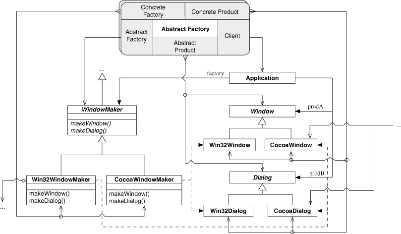
Figure 3.20. Abstract Factory as part of a larger UML diagram.
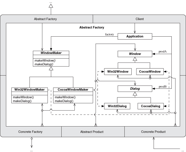
Figure 3.21. Abstract Factory subsumed within the expanded PINbox.
Now collapse the PINbox to the standard form, as in Figure 3.22. The diagram just got a lot simpler, didn’t it? Now you can see precisely what the new connections are. All the details of the design pattern instance have been replaced by a single PINbox. The PINbox now acts as an abstraction should, by subsuming the details that the abstraction represents and by making the situation easier to comprehend, not harder. See the discussion of Abstract Factory in Chapter 7, Section 7.1.1, for a use of an expanded PINbox to show the internal structure of the pattern.
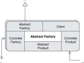
Figure 3.22. Coalesced PINbox.
In this case, if you wanted to reveal the details, you could expand the PINbox again. The act of removing the PINbox entirely and reconnecting the internals to the externals is called peeling. The journal article [36] mentioned at the beginning of this chapter expands on these ideas.
3.3. Conclusion
PIN is designed to be a simple and flexible way of visually describing design elements in software. It can be used by annotating other software design notations such as UML or as a standalone notation for showing the relationships between design elements such as design patterns independent of implementation needs. It offers the user nearly unlimited choice in degree of granularity of what can be exposed at a particular point in time, based on specific needs.