
2. Elemental Design Patterns
The Elemental Design Patterns, or EDPs, are, at their core, a catalog of the basic concepts of object-oriented programming. Two traits make them unique: First, they are written in the style of the design patterns literature. Each is treated as a standalone concept with a specific name by which it can be discussed and mulled over until it is understood. This book presents each EDP along with a problem that it is suited for and discusses when the pattern should and should not be applied. You will find example implementations, comments on possible consequences of using the patterns, and related patterns that you should look at as well. This human-oriented definition of each EDP provides you with a common term you can use to clearly and precisely converse with other students or developers about the concept.
Second, design patterns are descriptions of solutions to common problems that were found through the examination of existing software systems. EDPs are also solutions to common problems, and once you know what to look for, you will find them everywhere. They are in fact so common that, until now, they have not been considered worth writing up in any comprehensive way. EDPs were originally identified as a comprehensive body of interrelated design concepts not in software but in a formal description of software. EDPs arise from the mathematical foundations of object-oriented languages, but rest assured, with the exception of an appendix safely tucked in the back, this text is mathematics free. (I do hope you get curious and read the appendix, though—it’s rather interesting.) The solid yet simple ideas underlying the EDPs provide a strong framework on which to revisit these basic concepts, give them new life, and repurpose them for new applications. This foundation also gives you a compelling ability to use them as tiny building blocks, almost like atoms, to describe other design patterns in solid and direct ways. And, like atoms, you can build worlds with them.
This book gives you some background on EDPs, where they came from originally, and how they fit into the larger context of design patterns in programming. It also gives you just enough of a taste of object-oriented theory to understand how the patterns all relate to one another, but no equations, I promise. We discuss some of the ideas underlying the basics of object-oriented programming, much of which you may already be familiar with. Finally, you learn how that basic theory gives rise to a veritable stable of concepts that you can use in your everyday programming. Later chapters explain how you can use EDPs to make your designs better.
2.1. Background
The identification of EDPs had its beginnings in the System for Pattern Query and Recognition (SPQR) project at the University of North Carolina at Chapel Hill [35]. SPQR is a research project for identifying instances of known design patterns within an existing body of source code. It can find design patterns independent of the original source code language and can easily find various implementations of the same design pattern from a single pattern definition. If you’re interested in the inner workings of SPQR, further information is available [35, 37, 38], but a basic understanding provides enough context for our discussion of what EDPs are and how they are defined.
I was inspired to create SPQR while working as a professional software engineer. I was on a team responsible for one of three libraries used in a real-time commercial and military flight simulation system. In one of our joint all-library development meetings with the application team, they thanked us profusely for a feature we had just added, stating that it was exactly what they needed. We said they were quite welcome, that’s what we were there for, and so on.
After the meeting, the three library teams looked at each other and asked if the others knew what the application team had been talking about. None of us had designed the feature they were describing, we weren’t even sure how it had come about, or that it was possible. We decided to get to the bottom of it, thinking that certainly it couldn’t take much time.
Nearly 200 developer hours later, we had our answer. We had an instance of a Decorator pattern, one of the Gang of Four (GoF) patterns, embedded and hidden within the system. What was unique was that it didn’t live in any one library. Pieces of it were scattered across the three libraries, and the application team had stumbled onto their integration as a whole. We were stunned. A rather heated debate ensued: Was this really a design pattern? After all, it hadn’t been designed, it had just sort of grown.
Well, most software does just that. It grows organically, and often in unexpected ways. In managing software projects, we can only manage what we know, and knowing that there was this useful design element provided us an opportunity to enhance, streamline, and document its existence for developers to use effectively. Finding it—that was the problem. Remember, we had written the software in question, we were the experts, and it still took us an inordinate amount of time to deduce what was going on. Automation of the process was the obvious answer. As I mentioned in Chapter 1, what we really want is self-documenting code, or at least a system to extract that documentation. SPQR is such a system.
Creating SPQR necessitated solving a fundamental problem: I had to teach the computer how to identify design patterns. Patterns are not rote recipes; they are soft and amorphous things we humans call concepts. Most research and industry systems that attempt to find instances of patterns in source code do so by looking at patterns as constructs—as rigid forms that look like implementations—rather than as abstract concepts. This is a reasonable approach, and it treats patterns as many developers do: “This class has that field, and that subclass accesses it through a method named X,” and so on. The thing is, this approach once more reduces the design patterns to specific implementations. Every variation of a possible implementation requires a new definition. It’s the cut-and-paste methodology again [25, 30]. I don’t mean that this work is of low quality—far from it. These tools are stellar examples of the approach and are worth your investigation. They do their job well, and they add value if you happen to meet their requirements.
The problem with this approach is that defining a pattern for queries as a construct is highly fragile. What if the particular method you define wasn’t named X, but Y? What if the subclass wasn’t a direct subclass, but there was another class between the two in the inheritance hierarchy? Or what if the subclass wasn’t a true inherited subclass at all but used the superclass as a delegate object instead? None of these conditions would be found by a construct-oriented approach to design patterns, and they would require new pattern definitions. And that’s assuming you’re still working within one implementation language. Remember, patterns are implementation-language independent—the scope of the issue is much larger.
It seemed obvious that a different tactic was needed with SPQR. Diving into the background and history of design patterns yielded the necessary clue. The more I studied the GoF material and worked back through the inspirations that spawned it, the more I focussed on Alexander’s original work. As I read his first and, at least within the software engineering community, least-cited treatise on design patterns, Notes on the Synthesis of Form [4], I realized something important had been lost: patterns are concepts, not constructs.
This simple truth fundamentally alters what I was trying to teach the computer to recognize. Teaching a computer system to look for language constructs bolted together in rigid structures will never give us the flexibility we desire with the accuracy we need. Instead, we should be teaching a system to look for programming concepts because that’s what patterns really are.
Unfortunately for this particular task, the established design patterns literature is primarily geared toward describing high-level, abstract concepts, which is part of what makes them so powerful—they lift the discussion of a design to a higher level of abstraction. Programmers generally have a good working handle on lower-level abstractions, so establishing them as patterns has never seemed necessary. The design patterns community is rightly focused on documenting those lessons that are not already ingrained and well understood. These design patterns described by the software community tend to be at the larger end of the spectrum. Computers, on the other hand, are fundamentally only as knowledgable as the foundation we can teach them. For SPQR, we had to establish a chain of concepts from the ground up so it could help us deal with the concepts of programming. We had to fill in the gap between the highly rigid pieces of an implementation and the sometimes fluid concepts that they represent.
In doing so, it became apparent that the EDPs were just that—design patterns that form a fundamental basis from which to describe software design not just for automated analysis but for humans as well. This book is a partial catalog of the EDPs written for human, not machine, consumption. It is intended to be used by developers, students, and designers to help fill in the gaps in our understanding and our language when discussing software design. As expected with design patterns, each EDP has an informal write-up, or pattern specification, to use an accepted term, and also has an origin as a mathematical construct. This latter trait makes the EDP catalog unique. Each EDP is an abstraction of programming that lets us talk about even very small issues of software design independent of precisely how they are implemented.
This brings us to two ways of describing EDPs: their basis in theory and their genesis in pragmatism. The following section intertwines the two while keeping the formalisms to a minimum. You don’t need to precisely understand the formal foundation at a mathematical level to continue in this book, but you may find it illuminating if you wish to move in that direction. If you find yourself wondering about the underlying mechanics and want a stronger understanding of how design patterns and programming language theory intersect, you can start in the appendix, which describes the ρ-calculus that forms the foundation of this body of work.
2.2. The Where, the Why, the How
Teaching a computer to look for the large-scale abstractions and concepts called design patterns, as they exist in the common literature, is a difficult task. What do we do when faced with a large and gnarly task in computer science? We break it down.
Deconstructing the design patterns literature is not a simple thing. A few attempts have been made over the years [12, 17, 32, 40, 41, 43], but they have been partial deconstructions, seen as oddities or curiosities by most developers and researchers outside the immediate field. After all, these smaller deconstructed pieces and concepts are obvious, right? They are basic concepts, basic things we deal with every day, so why bother describing what we already feel we know?
Well, if they’re so obvious, how come they’re not already documented?
The basic concepts of software design are as “obvious” as the “correct” way to build a domicile: it depends entirely on your context, your experience, and what you were taught. Someone who was trained in functional programming in ML understands recursion very differently from someone whose primary background is C. The two developers will have different assumptions about recursion, where it is useful, and how it should be applied, even though the basic underlying problem that it is solving is the same. Given the discussion of housing styles in Chapter 1, this idea should start to sound familiar.
I said earlier in this chapter that the lower-level concepts of programming have not been a primary target of the design patterns community because the literature is aimed at documenting concepts that are neither ingrained nor well understood. Simple concepts are seen as ingrained and therefore outside of that scope, but that doesn’t mean they’re actually well understood.
The low-level concepts we use in programming are unselfconscious, as Alexander defined it. We learn them more or less by rote in class and in the field, and we apply them because “that’s the way it works,” without having to make conscious decisions to do so. Most of us never study the principles underlying those concepts, but they exist and are well understood at a mathematical level.
Those concepts just haven’t been properly exposed at a human level, and that’s what EDPs are. In a nutshell, EDPs are the underlying core concepts of programming and software design that have remained mostly undescribed. Those that have been described have not been related to one another in a meaningful and well-founded manner until now. Each EDP is a selfconscious description of a core concept. The EDP catalog as a whole relates the EDPs to one another to form a conceptual framework that the student or developer can use to understand other patterns. It provides a taxonomy and lexicon for describing higher-level abstractions, homogenizing the language and abstractions such that when any two developers reference, for example, the EDP Extend Method, they both have a precise understanding of a common definition.
EDPs provide a language with which to reason about, describe, and discuss software, from the most fundamental levels on up. Mainstream design patterns have done an amazing job of providing this knowledge base for the seasoned pro, but until now, no one has aimed that same tool at the novice or student in a comprehensive way.
So how far can we deconstruct these concepts from the design patterns literature? As an example, let’s look at Decorator.
2.2.1. Decomposition of Decorator
A quick note on naming conventions before we go any further: pattern names in this text are italicized and capitalized—for example, Extend Method. Types and classes in examples are capitalized and set in monotype font. Fields and methods are set in intercaps, or “camelcase” and in monotype font, as in thisIsAMethod(). Code examples use the same system.
The canonical example Unified Modeling Language (UML) for Decorator, as provided in the GoF’s Design Patterns [21], is shown in Figure 2.1. For now, you don’t need to understand what Decorator is; a visual inspection of the UML diagrams should suffice. In general, Decorator is a popular and commonly used design pattern that provides a mechanism for behavior to be extended dynamically at runtime. You can think of it as an internal plug-in or extension system, like you would find in a web browser.
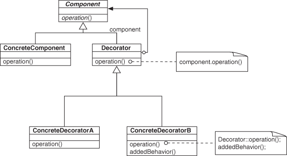
Figure 2.1. Decorator’s usual example UML.
Suppose you want to decompose Decorator to better understand it. It is, after all, a rather high-level abstraction. If you can absorb smaller pieces individually, you can almost certainly have an easier time understanding the pattern. Better still, you should be able to use those smaller pieces to help you understand other design patterns you may encounter, as long as they’re described in similar terms.
It’s not unlike trying to understand how a complex piece of machinery such as a race car works. You can buy one, put it in your garage, break out the tools, and disassemble the whole car, or you can learn about the pieces individually. You can study the internal combustion engine, for instance, or the hydraulic braking system. Those systems can be further broken down into parts that you can investigate one by one to make the larger study task easier.
In the end, if you know how a gasoline engine works, you not only have the facility to comprehend that portion of the race car as a unit, as an encapsulated abstraction, but you can apply that knowledge to other vehicles, or even lawnmowers, generators, and any other gasoline-engine-driven machine. Decomposing design patterns serves a similar purpose: identifying the smaller pieces that you can treat on their own merits, learn thoroughly in more digestible chunks, and apply in novel situations.
After an exhaustive search of the existing literature on design patterns (and remember, there are thousands), you might notice that Decorator shares similarities with two other patterns.
One is Objectifier, first described by Walter Zimmer in 1995 [43], shown in Figure 2.2. Objectifier describes a way for a single object interface to represent multiple concrete implementations in a way that is opaque to a client. When a client requests a method to be invoked through the Objectifier interface, it does not know which of the two (or more) concrete method bodies is executed.
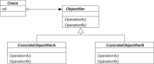
Figure 2.2. Objectifier as UML.
The other is Object Recursion, outlined by Bobby Woolf in 1998 [41], shown in Figure 2.3. Object Recursion chains together two objects with related types.
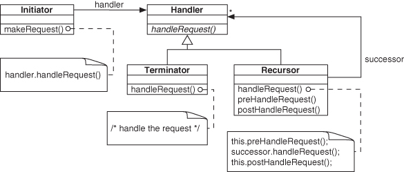
Figure 2.3. Object Recursion as UML.
Looking at the UML diagrams in Figures 2.2 and 2.3, you can see that Objectifier and Object Recursion look quite a bit like pieces of the Decorator pattern. Although they are not exactly the same, certain features in their structure of the UML are similar enough that we can describe parts of Decorator in terms of these other patterns—we can say that Decorator is composed of these patterns.
A closer look shows that Objectifier can be considered a part of Object Recursion. Object Recursion uses Objectifier as the backbone of its form, but it adds a link between one of the concrete implementations and the interface, and it does so for the same method. In other words, when the Initiator class calls handleRequest(), by the intent of Objectifier, either the Terminator or Recursor class might handle it. If Terminator handles it, the request is complete. If Recursor handles it, an additional call is made through the interface for another handleRequest(), and the process starts over again. This chain continues until Terminator is the handler, at which point the chain, unsurprisingly, terminates.
Given this series of actions, we can say, “A Decorator uses Object Recursion to traverse a chain of objects, presumably at least two in length, and perform the same method call on each.” That seems rather vague, though, and it also misses a lot of the detail in Decorator. We should have a better decomposition to work with, but at least we know that patterns can be described in terms of smaller patterns.
2.2.2. Down the Rabbit Hole
We’ve established that we can build Decorator from some smaller pieces, but are these pieces as small as they can be? What is the smallest deconstructed pattern we can make that is still a pattern?
To answer that question, we need to ask again, What is a pattern? We know it is a concept, we know it is an element of design, and we know has certain critical components. Let’s set aside the question of what a concept is and address the other two portions. Design is the manner in which parts of a whole interact with and relate to one another, as illustrated in the outline of a design pattern written in the accepted canonical format popularly described in the GoF text. GoF’s outline shows that participants and collaborations are core pieces of a design, and that they highlight both the parts of the design and how they interact with and relate to each other.
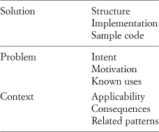
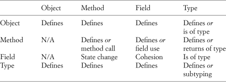
Consider a common definition of design pattern: “A common solution to a common problem within a particular context.” Most of the pieces of a canonical format design pattern specification can easily be placed into those three categories: solution (or implementation), problem (or description), and context (or environment), as in Table 2.1. The structure, implementation, and sample code are unmistakably the solution. The intent, motivation, and known uses describe the problem space. The context, the environment in which the problem occurs, guides applicability, frames the discussion of possible consequences, and often indicates if the current pattern isn’t exactly right and which of the related patterns is a better choice.
Table 2.1. Pattern pieces sorted into three categories of a pattern definition
After sorting these elements we have two parts left that don’t easily fit into one of those three categories: participants and collaborations. They’re obviously part solution in that together they form much of the solution. But they’re also part problem description because they almost always directly reflect how the problem is phrased. Finally, they’re part context in that they are created in response to the needs of the environment in which they are placed. They describe the parts and their relationships that lie at the intersection of the three arms of a design pattern.
Relationships form the core of design. The design of a car is more than a pile of pieces: it is also a blueprint for how they fit together. A house is more than a stack of lumber, a case of nails, and some copper piping; it has a form, or plan, that fights entropy and, we could say, keeps the structure at a higher energy level than just a rubble pile. The parts list ensures that you have everything you need to begin building, but the relationships in the design tell you how to make them work in concert.
Let’s flip the question around a bit: What is the smallest relationship we can define? Well, that one is easy. A single relationship between two things is simplest. Now we can apply this insight to the deconstruction of design patterns.
This gives us a clear goal. With each subsequent smaller design pattern, we can look at it with a critical eye and ask, “Does this embody more than one relationship?” If not, then we’ve definitely reached our goal. If so, it’s still possible that we’ve done so.
Why would we already “possibly” be done if there is more than one relationship involved? Well, not all relationships are created equal. Some are quite important when discussing design, and some are there to provide a context. The primary contextual relationship is that of scoping, and it appears in many forms.
Whenever you declare a variable, define a method, or describe a class, whatever that new item “lives” in is called its scope. The scope is how that element is made unique from all others in the system. If you have two classes, each named Menu, but one is defined in a package named GraphicalUIElements and the other is defined in a package named RestaurantNecessities, you can be pretty sure that they’re not the same thing. Their scope indicates that they are distinct classes, never to be confused. This principle applies any time there is an enclosing something that has a name and within which you define something new.
Classes are scopes for the methods and fields they define. Namespaces and packages are scopes for anything inside of them. Methods and functions are scopes for the local variables declared within them. Over and over again we see the same mechanism at work in many different language features. To access a specific element, we state precisely which one we want by providing the scopes from the top down. Unfortunately, it isn’t always this simple. Sometimes these scopes are implicit, and we can leave them off, such as when referring to a local variable within a method or to another member within a class. Furthermore, despite their common behavior, these scopes can have different syntaxes through which they are accessed. For instance, in C++, to access the Menu class within the GraphicalUIElements namespace, we would state it as GraphicalUIElements::Menu, using a double colon. Given an instance of that class, however, we would access its list of menu items as aMenu.theItems, using a dot operator. Both of these techniques specify which element we wish to select from a scoping element, but they do so in different ways. This text defines a single way in which we can treat all scoping, regardless of how it is implemented for specific language features within specific languages.
Consider class A that has a method f, and class B that has a method g, as shown in UML in Figure 2.4 and in code in Listing 2.1. A has a field b of type B. In the main() body, an instance a of type A is instantiated, and then a.f() is invoked. The method f() is scoped by the object a. In object-oriented languages, functions and methods are always enclosed by some scope, even if the scope is implicit.
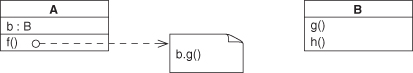
Figure 2.4. A simple method call as UML.
Even in C++ global functions and fields can be considered as though they reside inside an invisible and implicit object representing a global namespace, which is how the runtime effectively treats them. Check Clause 3.3.6 [basic.scope.namespace], paragraph 3, of the 2011 C++ ISO Standard Working Draft [6] for confirmation. Further, the use of file-scoped elements in C++, those declared global and static, is now discouraged by the conventional wisdom in favor of unnamed namespaces, which perform the same function more explicitly. In other words, each translation unit gets its own object for scoping, and the fact that the scope has no name means it can’t be used outside that translation unit. Again, objects are being used to scope and wrap elements that have previously been considered as freely roaming.
Listing 2.1. A simple method call as pseudocode.
1 class A {
B b;
3 f() {
b.g();
5 };
};
7
class B {
9 g() {};
h() {};
11 };
13 main() {
A a;
15 a.f();
};
Getting back to the code example, a.f() in turn calls b.g(), and a relationship exits between those two methods. The relationship between a and f, one of enclosure or scoping, is contextual. It helps specify which method we are talking about. A similar relationship exists between b and g. The call from a.f() to b.g(), however, is not just contextual, it is the primary relationship between those two methods. In other words, this is the relationship we’re interested in, but we have to use scoping to get there.
Scoping relationships help us refine our view to a particular design element. We need exactly two such design elements to form the single relationship described in an EDP. There may be a number of scoping relationships that set up the final single relationship we are interested in, but we are not immediately concerned with them. They are part of the description of the elements of programming that comprise the endpoints of the relationship we wish to work with. Returning to our earlier metaphor of housing styles and design, the scoping elements are a bit like stating that a piece of wood is a two-by-four or a half-inch-thick sheet of bias-grain plywood. That information doesn’t tell us how to orient one to the other or where to drive the nails. Scoping provides a context to help define what an element is, but it doesn’t do much to explain how that element relates to others in the system.
We can now tweak our question of whether we’ve reached our decomposition goal to, Does this embody more than one relationship of interest?, which gets us closer to our goal. Now we just have to determine what a relationship of interest is. So far, we’ve described scoping relationships, which include class ownership of methods and fields, as well as namespaces, packages, and all the other grouping techniques available in programming, and we stated that we’re not interested in them at the moment. Let’s consider instead what remains that we could form relationships between.
What remains are classes, their fields and methods, and little else. One item seems to be missing from the list: objects. It is object-oriented programming, after all! We’ll add objects to the list for completeness, and later we’ll show how they’re central to this approach. (For a formal explanation, see the appendix.) For now, we have these four kinds of programmatic entities on our list: objects, methods, fields, and classes, or types. This may seem like an odd thing to do, but it actually makes solid sense.
We don’t call them classes, because not every object-oriented language has classes, but every object-oriented language has types. Remember that we’re looking to describe design patterns in a way that can cross language borders, so we’re going to be looking for features that are common to, and a requirement for, each and every object-oriented language. So how do we make the transition from classes, which most people are familiar with, to a more classically “pure” object-oriented approach? It’s not that complex, really: it simply involves splitting a class into its constituent parts.
A class is an interesting beast in that it is so common in most object-oriented languages that many students and developers consider it a primary and necessary element. The reality, from a strictly object-oriented viewpoint, is that it is not. Some languages, such as Self and Lua, don’t even have the concept of a class. Instead, they rely on prototyping, cloning, and other actions on objects to perform the same functions. It’s not just esoteric languages that exhibit this use of objects in places where most languages use classes, as a variety of this usage can be seen in JavaScript. Even Smalltalk, arguably the progenitor of most object-oriented languages, has a quite different implementation and understanding of a class even though the same term is used.
In general, a class in current common object-oriented languages such as C++ and Java performs two duties. First, it describes the elements that will be in instantiated objects of that class, the member methods and fields. Most of us expect a class to be used in this way. Second, it describes elements that are common across all instantiated objects of that class, the class methods and fields. This is what happens when, in C++ or Java, we declare a method or field to be static. The first use case corresponds directly to a type in the formal sense, and the second use case can be re-created using a special-purpose object. Consider a field declared static in a class in C++ and how it is accessed, as in Listing 2.2.
Listing 2.2. Fields within classes, instances, and namespaces, as defined and used in C++.
namespace MyNamespace {
2 int aField;
};
4
class MyClass {
6 public:
static int sharedField;
8 int instanceField;
};
10
main() {
12 MyClass mc;
mc.instanceField = 0;
14 MyClass::sharedField = 1;
MyNamespace::aField = 2;
16 };
Notice that in main the use of the class field sharedField is prefaced by the class name MyClass. This is exactly the same notation used to access aField in the defined myNamespace. We can think of the entity that holds the class-shared elements of a class as a “live” object, and we can think of a namespace in the same way. We provide the name of the object and the piece we want selected out of it, just like any object that was instantiated from a class in the normal way. When the language provides a namespace, a package, or a class, it is providing a way of instantiating these objects automatically.
Still not convinced? In Smalltalk, the class is represented by an object. Literally, it is named the class object. To instantiate an object of that class, we send the class object a message—the Smalltalk equivalent for “call a method of the object”—to return an instance of that class. Class methods and fields live in that class object. It is almost exactly the scenario we are describing here.
Or, look at Java. In Java the class object is a special object that is available for inspection through reflection and is associated with a class that a developer defines. Unlike in Smalltalk, it is not directly accessed by the developer in “normal” use but is usually reserved for more complex reflection actions. The same basic principle applies as in Smalltalk, except that the new MyClass construct borrowed from C++ hides the process under a bit of syntactic sugar.
Listing 2.3 shows a Java snippet in the top half and one possible decomposition of the class in the bottom half. If you think of the usual new MyClass as being a synonym for MyClass_Object.new() in this case, and then access to the static members being done through the MyClass_Object instead, as in MyClass_Object.sharedData or MyClass_Object.sharedMethod(), then it’s not that different than what you may be used to in Java already. Similar mechanisms are available for C++, where no reflection option exists.
Listing 2.3. A Java class, and one possible equivalent object and type.
class MyClass {
2 public:
static int sharedData;
4 int instanceData;
static void sharedMethod() { ... };
6 void instanceMethod() { ... };
};
8
10
MyClass:
12 int instanceData;
void instanceMethod();
14
MyClass_Object:
16 int sharedData;
void sharedMethod();
18 MyClass new();
Although the details of how it is handled will differ from language to language, in every case a class can be emulated using a type and an object. While this may sound a bit foreign to you at first, it quickly becomes second nature in practice. Just remember that a class with no static members (using the C++ and Java terminology) is just a type. Any defined class members would be moved into a corresponding class object, as in Smalltalk, or into the reflection-accessed Java class object.
We needed types in order to satisfy basic properties of typed languages, and objects are the core of object-oriented languages regardless of their class features. By using these two in conjunction, we can emulate classes from class-based object-oriented languages. This allows us to simplify our set of items needed to define design patterns to just our four previously mentioned items: objects, methods, fields, and types.
In what ways can the items on this short list interact? Table 2.2 is a complete list of possible ways in which the entities in the left column can interact with the entities on the top row. Objects and types can contain, and therefore define, any of the four elements, but we’re going to eliminate those “contains” relationships from consideration under the scoping mechanism. Methods can, in some languages, similarly define, or scope, inner methods or types, and of course we can define local variables or fields. Methods can also call other methods, use nonlocal fields, and have a return type. Fields are simpler in that they can be assigned the return value of a method or of another field. And, of course, they have a type. Finally, types can define through scope any of the four entity kinds, and types can rely on other types through subtyping.
Table 2.2. All interactions between entities of object-oriented programming
Not that many interactions are possible now, which means that we can start enumerating them into a finite and, better yet, quite small set of possibilities. Table 2.3 shows the interactions that don’t include defining another entity.
Table 2.3. Nonscoping interactions between entities of object-oriented programming
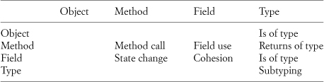
A field has a type on which it relies; this is simply the type of the field. The same holds for objects. Similarly, methods have return types. They are used to define what a piece of data is, whether it is a field or another object such as a parameter or a return value from a method. Much like scoping, defining data has the feel of describing the object or field itself, not providing a relationship between two entities.
For instance, look at the code snippet in Listing 2.4. The data member pos is defined as being an instance of the type Position. This tells us what pos is, and its scoping within Glyph tells us some of how to interpret it, but it doesn’t tell us how pos interacts with other elements in the system. Similarly, the types of the parameters to the scaleCopy method only tell us what those parameters are, not how they relate to anything else.
On the other hand, other relationships, such as a type relying on another type, provide more information than just a description of one element. Type reliance on other types, which is most often seen as inheritance, is rather well documented. We might even say it is ingrained and understood.
Listing 2.4. Typing as context.
class Glyph {
2 Position pos;
Glyph scaleCopy( float x, float y );
4 }
For the purpose of defining the EDPs, there are only the four basic relationships left in the center of Table 2.3, where either a method or a field relies on another method or field for its value, to get its job done, and so on. Those relationships are a method call (method relies on method), a field use by a method (method relies on a field), a field being set by a method (field relies on method for a state change), and a field relying on another field, such as a = b + 1. As shown in the preceding tables, we can call these a method call, a field use, a state change, and cohesion. Believe it or not, nearly this entire book concentrates on just the first one, a method call reliance. Yes, there is a lot to be said about a simple method call reliance when looked at in the right light.
It has probably occurred to you that a method call looks an awful lot like a structural entity, not a conceptual one. This is true, and that’s why I started sneaking in the word reliance earlier. A reliance by one element on another doesn’t require a direct connection. Consider a method f that calls method g in its body. We say that f relies on g. Now assume that g in turn calls another method h, as in Listing 2.5. We say that g relies on h. It should be self-evident that this relationship is transitive—if f relies on g, and g relies on h, then f also relies on h. It’s not a direct reliance, but that doesn’t really matter: f still relies on h to complete its work so that f can do its work.
Let’s turn this around a bit. If we want f to rely on h, does it matter if it is a direct method call or if method g is in the middle? It does not. As long as f relies on h by some path, our requirement holds true. We just made the leap from a structural connection, that of a method call, to a conceptual connection, that of a method call reliance. This frees us from having to discuss low-level programming concepts of design in a structural manner and enables us to describe them in the conceptual way outlined earlier as necessary for working with and finding design pattern instances with SPQR. We discuss this in more detail and show how it forms a critical portion of working with EDPs in Chapter 4, Section 4.1.1.
In the process of teaching SPQR about programming concepts, we made the transition away from rigid structures of programming and instead gained a flexible and forgiving way to describe the relationships that form software design. By using these same techniques ourselves, we provide developers and designers with the same flexible thinking and ability to abstract design from implementation in a methodical yet understandable manner. We get double duty out of the same approach.
Listing 2.5. A method call chain as pseudocode.
function f() {
2 g();
};
4
function g() {
6 h();
};
8
function h() {};
10
function main {
12 f();
};
So let’s recap. We have reduced our list of interesting elements of programming to just four: objects, methods, fields, and types (which, depending on your implementation language, you may think of as classes). Other programmatic entities, such as namespaces, packages, and so on, help us describe which element we’re looking at, but they don’t create the kind of relationships we’re focused on when inspecting nontrivial design. Of those four elements, there are really four relationships, or reliances, that we’re most concerned with: method–method, method– field, field–method, and field–field. We concentrate almost exclusively on the method–method reliance in this book.
Can this one reliance, based solely on method calls, really do anything useful to help us describe the larger design pattern literature? Given the right context, anything is possible.
2.2.3. Context
The previous section was all about finding the right relationships for our discussion. We focused on primary reliances such as those between methods and fields, bypassing other kinds of relationships, such as type–type reliances or inheritance. Now it’s time to bring these contextual relationships back into the discussion.
For a given method call reliance, there are three other pieces of information we can work with to help us figure out what the purpose of that reliance is in a particular design. These are obvious if you look at a method call, as shown in Figure 2.5. In object-oriented theory, there’s really no such thing as a plain method or function. This isn’t that unusual. In hybrid object-oriented programming languages such as C++, you can put functions in the global space. In more pure languages such as Java, you cannot; each method must be in an object, either as an instantiation of a class or as a static class-level method, which is equivalent to placing the method with the class-object for that class. Let’s assume that every method must be embedded within an object. For any given method call reliance, then, there are four pieces: the calling method, the called method, and the object (class-object or instance) each resides in. Listing 2.6 sets up the classes and objects for such a method call in C++. Figure 2.5 illustrates the four pieces of the method o.f() calling the method p.g(). These pieces are present in every method call.
Figure 2.5. The parts of a method call.
Listing 2.6. Simple method call for Figure 2.5.
1 class Class2 {
void g() {};
3 };
5 class Class1 {
void f() {
7 Class2 p;
p.g();
9 }
};
11
void main() {
13 Class1 o;
o.f();
15 };
The three pieces of information hiding in plain sight are:
1. The similarity between the enclosing objects
2. The similarity between the types of the enclosing objects The
3. similarity between the calling method and the called method
I’ve introduced a new word here: similarity. Colloquially, it means what you think—a resemblance between two things. But what does it mean in the context of method call reliance?
Object similarity is the extent to which one object is like another. Is it the same object? Is it an alias to the second object through a pointer? Is it completely unrelated?
We can also discuss the similarity of relationship between the types of the objects. Are they the same type? Is one a subtype of the other? Or maybe one is a sibling type of the other, with a common supertype ancestor?
Method similarity is a bit trickier. We need to determine whether two methods are trying to do a similar task. We could look at many aspects: we could map keywords in comments, perhaps, or do a full analysis of the method bodies to determine what they computationally accomplish. There is a much easier way, however, if we take a page from social engineering and look at the method names and, to a lesser extent, the method signatures.
No, really. Think about it for a moment. What’s the primary means by which a developer conveys the intent of a method? The name. This is even ensconced in Kent Beck’s [5] Intention Revealing Selector pattern (emphasis mine): “You have two options in naming methods. The first is to name the method after how it accomplishes its task. . . . The most important argument against this style of naming is that it doesn’t communicate well. . . . The second option is to name a method after what it is supposed to accomplish and leave “how” to the various method bodies. This is hard work, especially when you only have a single implementation. Your mind is filled with how you are about to accomplish the task, so it’s natural that the name follow how. The effort of moving the names of method from “how” to “what” is worth it, both long term and short term. The resulting code will be easier to read and more flexible.” Beck sums this up as, “Name methods after what they accomplish.”
Robert Martin’s Clean Code [27] spends an entire chapter on naming alone, because it’s so important. Perhaps this can be best encapsulated using that text’s invocation of the old adage “Say what you mean. Mean what you say.” This is just good practice, and although not every developer group will follow it religiously, it is common enough that it can be leveraged to save us a tremendous amount of hard work. At worst, we can fall back on synonym lookups and word reordering for realizing that makeAString and stringCreator are close in intent, but it’s rather shocking how often a simple lexicographic comparison will do in most cases.
Overloaded methods, those with the same name but different argument lists, offer a small hiccup, but again, we can look to how human developers reason about similarity for clues. A method is more similar to one with the same name but a different argument list than it is to a method with a completely different name. A perfect match is one with the same name and the same argument list. For the purposes of this text, however, we can set aside this detail.
This algorithm is what SPQR uses with stunningly good results. I originally selected the algorithm solely because it was the simplest to implement, and I never expected it to actually work. It was to be only a placeholder until an appropriate approach could be selected after initial testing. Once SPQR started producing data and it became obvious that this method was sufficient for most cases, the reason why had to be worked out. It’s obvious in retrospect, but then, unexpected discoveries usually are clearer in hindsight.
We shouldn’t have been surprised that this approach worked. When a developer reads code to try to ascertain its purpose, the first thing he or she does is look at the names of things as clues to what they do. This is Beck’s naming principle at work– we expect things to be named appropriately, and more to the point, consistently. We expect things that perform similar functions to have similar names. All we’re doing here is leveraging that expectation. SPQR was simply taught to do the same thing we all do when reading code: to try to ascertain how things relate to each other. In turn, that experience guided the formation of the EDP catalog by providing a better understanding of how humans perform that task and offering a simple and natural way to describe our third similarity.
For any method call, we can therefore look at the objects involved, the types of those objects, and the similarity of the methods through some fairly simple analysis, whether automated or manual. What does this give us?
It gives us three independent axes of context in which to place and describe any method call. We can think of these three axes as defining a three-dimensional space that we can start to explore. Any method call will, depending on the similarity assessments for our three contexts, sit in exactly one spot within this space. In other words, all method call reliances that share the same space have a similar form, and we can describe those forms independently of who wrote them, how they were written, the software system they appear in, or even the language used to implement them.
We can describe the reliances on the basis of what they do for us and what we intend when we use them. We can discuss when they’re best used, how they relate to other reliances around them in that three-dimensional space, and how to transform from one method-call reliance to another.
This gives us the first group of the EDPs.
2.2.4. The Design Space
Sticking with our method call reliance, let’s explore what this three-axis-defined space might look like. We have three orthogonal and independent ways of describing a single method call based on three relationships: the objects that enclose the methods, the types of those objects, and the methods themselves.
This may seem like a lot to remember, but it’s easy enough to visualize. For simplicity, we can start with method calls in which we ignore the object type relationship, instead concentrating on the object and method similarities, as in Figure 2.6.
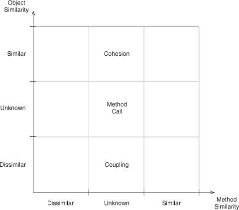
Figure 2.6. A simple design space.
We have a three-by-three grid and, along each axis, positions for similar, unknown, and dissimilar. Unknown is included for reasons that will be explained shortly. It should be pretty obvious that the center square is just a plain, vanilla method call. We don’t know anything about the objects or the methods involved. Surprisingly, this is where most software analysis and research lives. When someone talks about method calls without indicating a relationship between the methods, their enclosing objects, or the types of those objects, then all of those method calls live in that one square. All of them.
In the top center square, we have method calls with object similarity. For the purposes of this discussion, let’s just call that similarity object equivalence. These are method calls within a single object, known as an object’s cohesion, or how tightly it is bound with its own methods [42].
In the bottom center square, where we have dissimilar objects, or for this discussion, different object instances, method calls form the basis for coupling, a measure of the binding between objects [15].
The top and bottom center squares together represent the core of a wide body of research [7–9,13,16,22,23,31,34], which, along with the original center square, form just one-third of the space we’ve defined. What is in the other two-thirds? The most interesting slots are those in the four corners, where we have knowledge of both the objects and the methods.
Figure 2.7 fills out these four corners with the names of the programming concepts associated with them. For instance, a method call from an object to itself, to the same method, is what we all know as Recursion. We can write this as in Listing 2.7, with recursion occurring within countDown(). That one’s easy and obvious, but what about the other three?
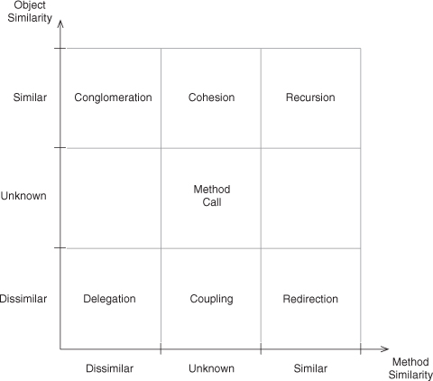
Figure 2.7. A simple design space with EDPs.
Listing 2.7. Example of a Recursion method call in Java.
1 class Timer {
public void countDown(int counter) {
3 if (counter > 0) {
this.countDown(counter--);
5 } else {
// Ignore this branch for now
7 }
};
9 };
Listing 2.8. Example of a Delegation method call in C++.
1 class VicePresidentOfSales {
public:
3 void increaseQuarterlySales();
};
5
class CEO {
7 VicePresidentOfSales vpOfSales;
void increaseProfits() {
9 vpOfSales.increaseQuarterlySales();
};
11 };
In the opposite corner, we see Delegation, which is a catch-all word used in a number of ways in software design. Here we give it a precise definition to mean a method call between two distinct objects and between dissimilar methods. An example is shown in Listing 2.8. Why use the word delegation? Because the calling method is delegating part of its work to another method in another object. It’s saying, “Go do this so I can get my work done.” It’s doling out a portion of its work that is part of, but unlike, its own intended task. Think about the CEO of a company delegating to the vice presidents in charge of various departments. The CEO has a job described as “run the company,” but each VP has a job described in different ways: “manage HR,” “ensure financial fidelity,” “investigate and deploy technologies in IT.” The CEO is asking each VP to do a task that looks nothing like his own, but each is critical to the CEO successfully completing his job.
Contrast this with the bottom right corner, labeled Redirection. The calling method is now asking another object to do some work, but it is asking for the same work to be done that the method itself is supposed to do. It is redirecting part of its workload to another object, but that part looks a lot like its own overall task. An example is shown in Listing 2.9. This is a bit like an assembly line branching out to work on multiple units in parallel during a particular task, then bringing the results back together onto one main line to continue to the next station. Imagine that your company is building cars, and you’re in charge of painting them. The long drying time, however, means that you would be holding up everyone else if you did them yourself in sequence. Instead of doing them all yourself, one at a time, you hire several teams and set up paint stations for each of them. Now you’re in charge of routing the cars to each one as they complete the previous one. Your job is to ensure the cars are painted. Their jobs are to ensure the cars are painted. Their job is a subset of yours that looks awfully similar. You’ve taken on a routing responsibility, but that’s only as part of completing your primary task: ensure the cars are painted. The routing is an implementation detail, the similarity in work between you and your subordinates is what makes this type of parceling out of work redirecting as opposed to delegating. Together, Redirection and Delegation form the basics of how objects can be coupled.
Listing 2.9. Example of a Redirection method call in Objective-C.
1 @interface Painter {}
-(void) paintCar: (Car) theCar;
3 @end
5 @interface PaintShopManager {
Painter subpainter;
7 }
-(void) paintCar: (Car) theCar;
9 @end
11 @implementation PaintShopManager
-(void) paintCar: (Car) theCar {
13 [subpainter paintCar:theCar];
}
15 @end
This leaves just the top left corner, the one marked Conglomeration. This is the flip side of Recursion, and together they define the backbone of cohesion. Conglomeration is the act of bringing together disparate elements into a whole—in this case, pulling together subtasks that look little like the main task (as in Delegation), but here just one object does the work. There are no other objects to delegate or redirect work to because this is a one-object task, but it is broken down into smaller portions that are handled by different methods within the one object. This may be done for readability, flexibility, or, as is often the case, marshaling together atomic behaviors into a more complex one some time after the atomic ones were defined. In any case, it involves one object and disparate methods, as shown in Listing 2.10, which revisits our Timer example from Listing 2.7.
These four basic concepts, Recursion, Delegation, Redirection, and Conglomeration, are four EDPs. Yes, they’re simple. Yes, they’re patterns that programmers use every day by reflex, but that’s rather the point, isn’t it? The uses are reflexive, not premeditated, and each has consequences for later implementation and design issues. If you’re new to programming, these concepts are not reflexive, not yet ingrained, and you may have questions about them. “When do I use them?” “What are they good for?” “What other concepts are related?” This is exactly the type of tribal wisdom that design patterns were created to express and pass along. Look ahead to the EDP entries in the catalog following this chapter for more detailed discussions of these four EDPs. Do so even if you’re a seasoned pro—there’s more there than you may first think.
Listing 2.10. Example of a Conglomeration method call in Java.
1 class Timer {
void goDing();
3
public void countDown(int counter) {
5 if (counter > 0) {
// Ignore this branch this time
7 } else {
this.goDing();
9 }
};
11 };
What about the final two entries in the grid where the object similarity is unknown but the method similarity is? Well, no one’s quite sure at this point. If you can think of what programming concept or design issue is addressed by those two spaces, there’s an opportunity for you to add to the EDP collection. This isn’t without precedent, after all. As developers stumble on new ways of using established pieces, some ways will be seen as useful and will develop semantics. These new techniques, if useful enough, inevitably end up in the next generation of languages as primary language features. You might be the person who helps define them. In the meantime, let’s remove the center column, where existing research sits, and the center row, which we’re really not sure what to do with yet. This leaves us with four entries in a two-by-two grid, as in Figure 2.8.
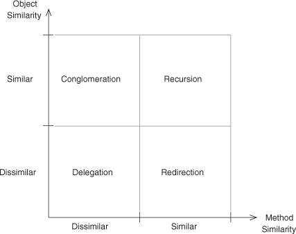
Figure 2.8. Our first four EDPs.
What’s interesting is that we derived these simple concepts from basic principles of programming theory. Once we start playing with the object types as well, the concepts become much more complex even though the theory remains just as simple. Let’s see what happens when we add that third axis.
Figure 2.9 shows the three axes. Where before we were not concerned at all with the object type, we can now work with the four entries we defined earlier for the object type similarity axis. The unknown entry has as little utility here, as it did in the previous grid, so let’s again remove it. For now we’ll concentrate on just the right-hand slice defined by fixing our method similarity to similar, as shown in Figure 2.10. The remainder of this space is more fully discussed in Chapter 5.
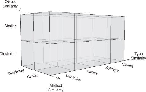
Figure 2.9. The design space extended to three dimensions.
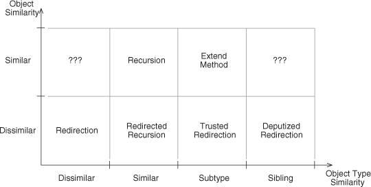
Figure 2.10. The design space with method similarity fixed to similar.
We can place Recursion on this grid by recognizing that the type of the object can’t be completely dissimilar for the object to be similar and calling a similar method.1 The definition of Recursion, however, is that the exact same method implementation is being called by itself, which does require both object and type similarity.
1. Does it have to be exactly the same? No! We’ll get to that in a moment.
Likewise, we can place Redirection on the grid by realizing that it is best descri bed as a dissimilar object and a dissimilar type. This is the most general form of Redirection. What happens when we make an incremental change, though, and we retain object dissimilarity but make the objects of the same type? This common design trait, where an object hands off a request to another object of the same type, forms a chain of like objects parceling out a task among themselves. Because this combines aspects of both Redirection (a dissimilar object) and Recursion (the same type), we use the extremely clever name of Redirected Recursion.2
2. We could have gone with Recursive Redirection, but in early feedback, that term implied to most people a loop between two objects, while this one did not, for some reason. Also, there’s a formal reason given if you care to dive in to the appendix.
Let’s continue this exploration of Redirection and change the type relationship a bit. If we redirect a method task to another object that is not of the same type, but a supertype of the current object, we can let an entire family of types handle the call polymorphically. You’ll notice that this is the first time polymorphism has explicitly popped up in our discussion. Until now, we talked about calls between similar (same) types and dissimilar (different) types, but we hadn’t refined the latter category. Now we have, and suddenly a whole new level of object-oriented design comes to light.3 This type relationship we simply call Subtype.4
3. If you’re unfamiliar with the term polymorphism, start with the Inheritance EDP. That will give you a good overview of the concept.
4. Recall that reliances go from the calling method to the method that is called; in this case the calling method is defined within a subtype of the type enclosing the method being called.
We can add one more subdivision of the dissimilar type bin, and that is the Sibling type relationship. A sibling relationship occurs when the types of the objects involved share a common ancestor supertype, but neither is a supertype of the other. We tossed the method call up our type hierarchy and then limited it back down to a trusted subset of that tree. We call this variation Deputized Redirection.
Let’s go back to Recursion, and then slide one square to the right, where the object instance is the same, but the type relationship is a subtype. Read that again. It actually does make sense to talk about having the same object, and a method call from that object to itself, but with two object types involved in that method call. In fact, to do so is super.
Specifically, super lets you access a supertype’s implementation of a method from within a subtype. In Java, it is done with the super keyword. In C++, an explicit type-scoping mechanism is used as in Supertype::. Other languages have a variety of mechanisms, but they all do the same thing—they give an object access to a supertype’s implementation of a method. How is this useful? Well, consider a case where you want to extend the functionality of a method, not completely replace it with new functionality. You would subclass the type, override the method, and then wrap a call to the original method in your bit of extra code. As you might expect, this EDP is simply called Extend Method.
Notice that in the preceding discussion, we took an existing, familar concept and moved just one space away from it at each stage, tweaking one detail or another at a time. The result of this simple progression is a surprisingly broad collection of concepts and design elements from programming. Look at the variety of the UML diagrams for the preceding eight EDPs if you’re not convinced that we’ve covered a lot of conceptual ground. Consider just the ideas involving Recursion and Deputized Redirection, shown in Figures 2.11 and 2.12. They look nothing alike, yet they sit just three steps from each other in the design space for a single method call.
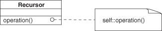
Figure 2.11. Recursion Example UML.
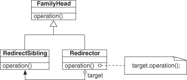
Figure 2.12. Deputized Redirection example UML.
Again, two mystery boxes remain. Let’s not ignore them this time but instead discuss what they could mean conceptually. In the first slot on the left, we have the same (or similar) object but utterly dissimilar typing on each side of the method call reliance. How can this be? Well, I’m not sure. Although some rather esoteric typing relationships exist out there, this one doesn’t make a lot of sense. For now, it is unknown territory, but perhaps a language will find a reasonable use for this context combination in the future. The BETA language [26], for example, has a unique inner construct that is the mirror image of super, creating a Supertype similarity instead of a Subtype similarity. This is exceedingly rare, however, and not used in our object similarity axis for that reason. It may be added later if it proves to be an interesting and viable design element.
An analogous situation occurs for the slot on the far right. Again, we have the same (or similar) object, but now a Sibling type similarity, and again, no language that I am aware of offers this possibility. These open slots are ripe for interpretation and thought experiment. Best of all, we can predict some properties for these undescribed entries in the design space, much like elements in a periodic table.
That’s just over half the method call EDPs that will be presented in full later in the reference section. It’s remarkable how many concepts can be expressed with a single method call, isn’t it? One method call. That’s all we’ve been discussing, and yet we have a wide range of design components to play with.
2.3. Core EDPs
To this point, we’ve discussed just method calls, but recall that we said there are three other forms of reliances that we can play with: field usage, state changes, and cohesion. What about those? Well, they are still being explored at the moment, fleshed out, and written up. Method calls were approached first because they’re the smallest, simplest design space to work with. The others are quite a bit larger. There are a few basic concepts that should be addressed, however, to fill out this first group, and they form the core of object-oriented programming from both formal and pragmatic points of view.
To begin with, there’s the entire “making objects” idea. It is one of the distinguishing characteristics of object-oriented programming, after all, or the entire paradigm probably would have been named something else. Look at the Create Object EDP for guidance here. At this vantage point, three decades or so into object-oriented programming, it seems odd that there was ever objection to it as a programming approach, but it had large hurdles to overcome. One objection was that anything that can be implemented in object-oriented programming can be implemented in procedural programming. While technically true—anything doable in any higher-level system is doable in procedural, in assembler, or in raw binary; otherwise it wouldn’t run—object-oriented programming allowed the easy enforcement of certain principles. Create Object outlines one of the major ones, creating a relationship between a single object and a single type at the same time.
Once we create objects, how do we get them talking to one another? Well, by using method calls, obviously. Okay, but how do we get them to find one another in the first place? We could statically create all the connections between the objects, but that’s rather limiting because it means the system cannot react to runtime input. The programmer must anticipate all possible uses of the system, including details such as maximal memory use for all possible data needs, regardless of the actual amount used. To get around this problem, we have to allow objects to gain access to other objects during execution. The Retrieve EDP does this, dynamically creating runtime connections between objects.
To instantiate an object, we need a type from which to do so. Often the types available to us are almost, but not quite, correct. Instead of rewriting a proper type from scratch every time, though, we’d like to leverage what we already have as a starting point. The ability to reuse types is made possible through Inheritance, another core EDP. Inheritance is a type reliance, which we mentioned earlier by one of its aliases, subtyping. It forms a connection between a base type and a type that relies on it for much of its basic functionality (methods) and state (fields). It allows a new type to reuse large chunks of logic and data in a well-formed way.
Another type-related EDP is Abstract Interface. It forms a reliance between two types that is a bit different in that only one end of the relationship is known ahead of time. It uses a method as a bridge between the two types. If a type declares a method to be abstract, it doesn’t have to—and in the strictest sense isn’t allowed to—give a method body implementation. This EDP creates a promise that at some point another type will inherit from this one and give the method a proper implementation. What that type is isn’t yet known, but it has to happen for this type to be usable. Until then, this type is incomplete.
These four EDPs, Create Object, Retrieve, Inheritance, and Abstract Interface, allow us to create objects with enforcement of certain guarantees, relate them to one another at runtime, define object types in terms of other types, and declare promises for future, unspecified types. Together, they form much of the basis for object-oriented programming. Along with the method call EDPs such as Delegation and Recursion, they provide a solid start to treating design as a reproducible discipline, one that uses well-formed building blocks connected in methodical and precise ways. Why don’t we see what we can do with just a handful of them?
2.4. Conclusion
This chapter introduced you to the Elemental Design Patterns. It gave a brief synopsis of the driving problem they helped solve and some background on how they came about. You saw how patterns such as Decorator can be described in terms of smaller patterns. This led to the conclusion that to better describe the more abstract design patterns in the standard literature, finer-grained patterns are necessary.
You were introduced to a minimalist form of object-oriented programming theory and shown how it gives rise to a small number of possible relationships, or reliances, that can occur in programming. These reliances form the basis for the smallest patterns we can define. One of these reliances, the method-call reliance, forms the core of this book. You saw that every method call has a context, defined by three simple pieces of information—the object, type, and method similarities—and that these create a design space in which well-known programming concepts live. The other three reliances—field use, state change, and cohesion—give rise to their own design spaces that are in the process of being defined.
The method-call design space was explored lightly. Code examples were given for many of the EDPs, and you saw how they relate to one another. Finally, you learned a set of the core EDPs, which define many of the basic concepts that underlie object-oriented programming.
You now have a solid footing to understand the importance and utility of the EDPs and are ready to start learning how to work with them. In Chapter 3, you’ll learn a valuable way to graphically depict pattern instances to help you visualize their interactions.