Construction of modern homes is to a very high standard of energy-efficient insulation and airtightness. Standards have gradually improved over the past 50 years, initially in response to diminishing fossil fuel resources and more recently due to concerns about the effects of atmospheric pollution and global warming. Older homes had varying degrees of air leakage and natural ventilation that ensured a healthy internal environment. A high envelope air permeability allowed air infiltration and leakage through the building enclosure. Examples include single-glazed windows with ill-fitting sashes, door and window frames not sealed to adjacent walls, doors without draught proofing, fireplaces with open flues and air vents/bricks in pantries and boiler room walls (prebalanced flue boilers).
By comparison with past standards, contemporary construction has the potential to encourage an uncomfortable and unhealthy internal environment due to the discomfort of living within an energy-efficient sealed external envelope. To avoid the symptoms of sick building (house?) syndrome (see page 311), mould growths, asthma and dust mite allergies, provision of air circulation must be integrated with building design.
Air infiltration can be achieved by natural or mechanical means. The former is partly achieved by background trickle vents in window frames and by air gaps or undercutting to internal doors. Natural ventilation by these means is difficult to regulate in defined quantities, therefore low-energy-use mechanical ventilation systems, particularly those with a heat recovery facility, are becoming quite common in new-build homes.
Building Regulations, Approved Document F1: Means of ventilation, supports provision of mechanical systems in homes that have an airtightness or air infiltration rate of less than 5m3/h per m2 envelope area at 50 Pascals (Pa or N/m2) test pressure. Most dwellings are now constructed to be tighter than this criteria.
Ventilation – a means of changing the air in an enclosed space to:
Provide fresh air for respiration – approx. 0·1 to 0·2l/s per person.
Preserve the correct level of oxygen in the air – approx. 21%.
Control carbon dioxide content to no more than 0.1%.
Concentrations above 2% are unacceptable as carbon dioxide is poisonous to humans and can be fatal.
Control moisture – relative humidity of 30% to 70% is acceptable.
Remove excess heat from machinery, people, lighting, etc.
Dispose of odours, smoke, dust and other atmospheric contaminants.
Relieve stagnation and provide a sense of freshness – air movement of 0·15 to 0·5m/s is adequate.
Measures for control:
Health and Safety at Work, etc. Act.
The Factories Act.
Offices, Shops and Railway Premises Act.
Building Regulations, Approved Document F – Ventilation.
BS 5925: Code of practice for ventilation principles and designing for natural ventilation.
Health Act.
The statutes provide the Health and Safety Executive with authority to ensure buildings have suitably controlled internal environments. The Building Regulations and the British Standard provide measures for application.
Requirements for an acceptable amount of fresh air supply in buildings will vary depending on the nature of occupation and activity. As a guide, between 10l/s of outdoor air supply per person can be applied between the extremes of a non-contaminated environment, to an extract air rate of 36l/s per person in a room where the atmosphere is contaminated, e.g. by welding fumes from a factory manufacturing process. Converting this to m3/h (divide by 1000, multiply by 3600), equates to 130m3/h per person.
Air changes per hour or ventilation rate is the preferred criterion for system design. This is calculated by dividing the quantity of air by the room volume and multiplying by the occupancy.
E.g. 50m3/h, 100m3 office for five persons: 50/100 x 5 = 2·5a/c per h.
Room/building/accommodation |
Air changes per hour |
|---|---|
Assembly/entrance halls |
3–6 |
Bathrooms (public) |
6* |
Boiler plant rooms |
10–30† |
Canteens |
8–12 |
Cinema/theatre |
6–10 |
Classrooms |
3–4 |
Dance halls |
10–12 |
Dining halls/restaurants |
10–15 |
Domestic habitable rooms |
1–4* |
Factories/garages/industrial units |
6–10 |
Factories – fabric processing |
10–20 |
Factories (open plan/spacious) |
1–4 |
Factories with unhealthy fumes |
20–30 |
Foundries |
10–15 |
Hospital wards |
6–10 |
Hospital operating theatres |
10–20 |
Kitchens (commercial) |
20–60* |
Laboratories |
6–12 |
Laundries |
10–15 |
Lavatories (public) |
6–12* |
Libraries |
2–4 |
Lobbies/corridors |
3–4 |
Offices |
2–6 |
Smoking rooms |
10–15 |
Warehousing |
1–2 |
Notes:
*For domestic applications see pages 239 and 240.
†18 air changes per hour is generally acceptable, plus an allowance of 0·5l/s (1·8m3/h) per kW boiler rating for combustion air. Double the combustion allowance for gas boilers with a diverter flue.
See also: BS 5925: Code of practice for ventilation principles and designing for natural ventilation.
Domestic Accommodation – Building Regulations
Approved Document F (Ventilation) provides the minimum requirements for comfortable background ventilation and for preventing the occurrence of condensation. It is effected without significantly reducing the high standards of thermal insulation necessary in modern buildings.
Definitions:
Habitable room – any room used for dwelling purposes, not solely a kitchen, utility room, bathroom or sanitary accommodation.
Bathroom – any room with a bath and/or shower.
Sanitary accommodation – any room with a WC.
Wet room – kitchen, utility room, bathroom and sanitary accommodation.
Ventilation opening – a means of ventilation, permanent or variable (open or closed) providing access to external air, e.g. door, window, louvre, air-brick or PSV.
PSV – passive stack ventilation is a system of vertical ducting from room ceilings to roof outlets providing ventilation by stack effect and wind passing over the roof.
Rapid or purge ventilation – openable window or mechanical fan system (see Note).
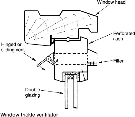
Background ventilation – permanent vents, usually trickle ventilators set in a window frame (see below). An air-brick with a sliding ‘hit and miss’ ventilator could also be used.
Whole-building ventilation – continuous ventilation through background/trickle ventilators or other purpose-made vents.
Note: With background ventilation, some part of the ventilation opening should be typically 1.70m above the floor to avoid draughts.
Note: Hinged or pivoted windows opening at least 30°, parallel sliding windows and external doors; height × width of opening min. 1/20 floor area of room served. 15° to 30°, 1/10 floor area. Less than 15° unsuitable.
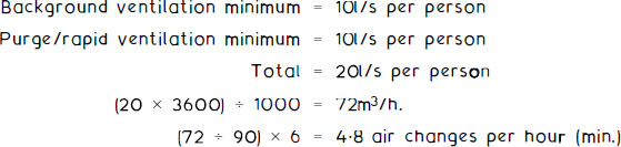
Habitable rooms – rapid or purge ventilation should be capable of producing four air changes per hour for each room, plus a whole building ventilation rate of not less than:

* Add 4l/s per person where occupancy is greater than two persons per main bedroom and greater than one person in other bedrooms.
* The minimum acceptable rate for any dwelling is 0.3l/s per m2 total internal floor area.
Kitchen, utility room, bathroom and sanitary accommodation – local ventilation by intermittent or continuous mechanical means, i.e. an extractor fan capable of achieving the following minimum rates (l/s):
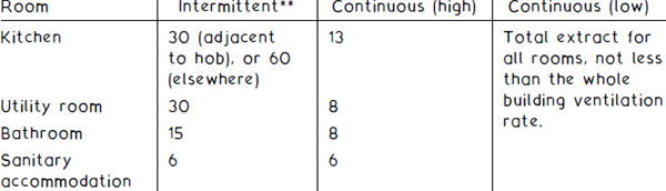
** 15min. overrun where fitted to an internal room.
10mm ventilation gap cut under all internal doors above the floor finish.
Alternatively, ventilation of dwellings can be provided by any of the following:
Background/trickle ventilators of at least 5000mm2 in each habitable room, 2500mm2 in wet rooms. Purge or rapid ventilation by fan or openable window to every habitable room. Intermittent extractor fans with background ventilators for kitchen, utility room, bathroom and sanitary accommodation as table above.
Passive stack ventilation (PSV) to kitchen, utility room, bathroom and sanitary accommodation. Positive air circulation from other rooms can be encouraged by undercutting all internal doors by 10mm (20mm kitchen) and omitting background ventilators in rooms with PSV extracts.
Purge ventilation and background ventilators to every habitable room (see page 244).
Continuous mechanical extract (MEV) with background ventilators to all rooms. Purge ventilation to all habitable rooms (see page 245).
Continuous mechanical supply and extract with heat recovery (MVHR). Purge ventilation to every habitable room (see page 246).
Mechanical supply ventilation, also known as positive input ventilation (PIV). Background ventilators to all rooms. Purge ventilation to every habitable room (see page 248).
Note: For specific requirements relating to each of the above alternatives, see Building Regulations, Approved Document F – Ventilation, Section 5: New dwellings.
Occupiable work rooms – will require a whole building ventilation air supply rate of at least 10l/s per person. Background or trickle ventilation can be used to satisfy this objective. As a guide, 4000mm2 ventilation area per 10m2 of floor area, with an additional 400mm2 thereafter for every 1m2 of floor.
Additional rapid or purge ventilation is also required for every unit of office accommodation. This may be satisfied with an openable window area at least equivalent to a percentage of the floor area as defined in BS 5925, or a mechanical air extract directly to outside, capable of at least 10l/s per person. For example, an office with an occupancy of six persons, floor area of 30m2 and a room height of 3m (90m3 volume):
Kitchen (for food and beverage preparation), washrooms, sanitary accommodation, photocopy and print processing rooms – local extract ventilation by continuous or intermittent means as follows:
Room function |
Local extract |
|---|---|
Printing and photocopying for more than 30 minutes in every hour |
20l/s per machine while in use If the room is permanently occupied, use greater value of extract and whole-building ventilation rate. |
Sanitary accommodation and washrooms |
Intermittent air extraction of: 15l/s per bath and shower. 6l/s per WC and urinal. |
Food and beverage preparation areas (not commercial kitchens, see page 238) |
Intermittent air extraction of: 15l/s for microwave and beverages only. 30l/s adjacent to hob with cooker(s). 60l/s elsewhere with cooker(s). |
Extract to engage automatically when food and beverage preparation equipment operates. |
Note: Passive stack ventilation is an acceptable alternative to use of local extract by mechanical means for sanitary accommodation and washrooms, and for food and beverage preparation areas. Further guidance and references for ventilation of non-domestic buildings, buildings other than offices and for buildings of specialised use is provided in:
CIBSE Application Manual 10, Natural Ventilation in Non-domestic Buildings, and Building Regulations, Approved Document F – Ventilation, Section 6: New buildings other than dwellings.
Natural ventilation is an economic means of providing air changes in a building. It uses components integral with construction such as air-bricks and louvres, or openable windows. The sources for natural ventilation are wind effect/pressure and stack effect/pressure.
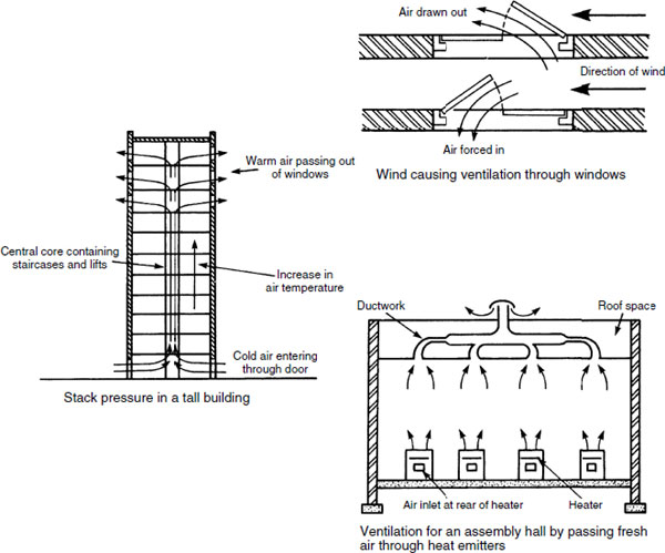
Stack effect is an application of convected air currents. Cool air is encouraged to enter a building at low level. Here it is warmed by the occupancy, lighting, machinery and/or purposely located heat emitters. A column of warm air rises within the building to discharge through vents at high level, as shown on the following page. This can be very effective in tall office-type buildings and shopping malls, but has limited effect during the summer months due to warm external temperatures. A temperature differential of at least 10K is needed to effect movement of air, therefore a supplementary system of mechanical air movement should be considered for use during the warmer seasons.
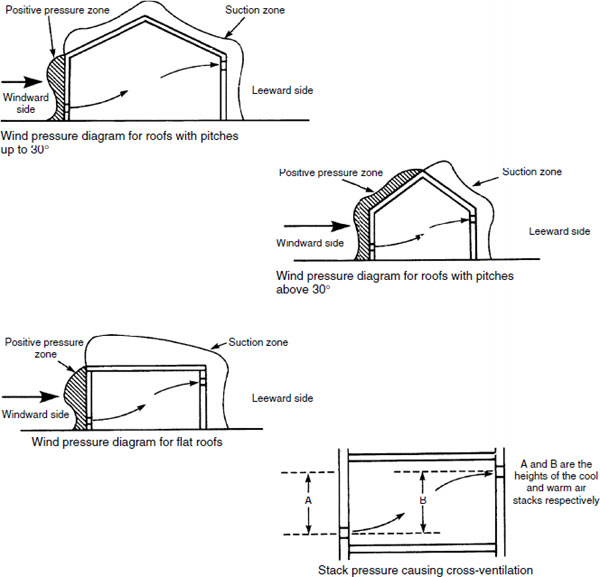
The rates of air change are determined by the building purpose and occupancy, and local interpretation of public health legislation. Public buildings usually require a ventilation rate of 30m3 per person per hour.
Wind passing the walls of a building creates a slight vacuum. With provision of controlled openings this can be used to draw air from a room to effect air changes. In tall buildings, during the winter months, the cool, more dense, outside air will tend to displace the warmer, lighter, inside air through windows or louvres on the upper floors. This is known as stack effect. It must be regulated; otherwise it can produce draughts at low levels and excessive warmth on the upper floors.
Ventilation and heating for an assembly hall or similar building may be achieved by admitting cool external air through low-level convectors. The warmed air rises to high-level extract ducts. The cool air intake is regulated through dampers integral with the convectors.
Natural Ventilation – Passive Stack Ventilation (PSV)
PSV consists of vertical or near-vertical ducts of 100 to 150mm diameter, extending from grilles set at ceiling level to terminals above the ridge of a roof. Systems can be applied to kitchens, bathrooms, utility rooms and sometimes sanitary accommodation, in buildings up to four storeys requiring up to three stacks/ducts. More complex situations are better ventilated by a Mechanical Assisted Ventilation System (MAVS) (see next page).
PSV is energy efficient and environmentally friendly with no running costs. It works by combining stack effect with air movement and wind passing over the roof. It is self-regulating, responding to a temperature differential when internal and external temperatures vary.

Ref. Building Regulations, Approved Document F1.
Mechanically Assisted Extract Ventilation Systems (MAVS or MEV)
MAVS may be applied to dwellings and commercial premises where PSV is considered inadequate or impractical. This may be because the number of individual ducts would be excessive, i.e. too space consuming and obtrusive with several roof terminals. A low-powered (40W) silent running fan is normally located within the roof structure. It runs continuously and may be boosted by manual control when the level of cooking or bathing activity increases. Humidity sensors can also be used to automatically increase air flow.
MAVS are acceptable to Approved Document F1 of the Building Regulations as an alternative to the use of mechanical fans in each room. However, both PSV and MAVS are subject to the spread of fire regulations (Approved Document B). Ducting passing through a fire-resistant wall, floor or ceiling must be fire protected with fire-resistant materials and be fitted with a fusible link automatic damper.

Mechanical Ventilation with Heat Recovery (MVHR)
MVHR is a development of MAVS to include energy recovery from the warmth in fan-extracted moist air from bathrooms and kitchens. The heat recovery unit contains an extract fan for the stale air, a fresh air supply fan and a heat exchanger. This provides a balanced continuous ventilation system, obviating the need for ventilation openings such as trickle ventilators. Apart from natural leakage through the building and air movement from people opening and closing external doors, the building is sealed to maximise energy efficiency. Up to 70% of the heat energy in stale air can be recovered, but this system is not an alternative to central heating. A space heating system is required and MVHR can be expected to contribute significantly to its economic use. MVHR complies with the ‘alternative approaches’ to ventilation of dwellings, as defined in Approved Document F1 to the Building Regulations.

Mechanical ventilation systems are frequently applied to commercial buildings, workshops, factories, etc., where the air change requirements are defined for health and welfare provision. There are three categories of system:
Natural inlet and mechanical extract
Mechanical inlet and natural extract
Mechanical inlet and mechanical extract
The capital cost of installing mechanical systems is greater than natural systems of air movement, but whether using one or more fans, system design provides for more reliable air change and air movement. Some noise will be apparent from the fan and air turbulence in ducting. This can be reduced by fitting sound attenuators and splitters as shown on page 253. Page 261 provides guidance on acceptable noise levels.
Internal sanitary accommodation must be provided with a shunt duct to prevent smoke or smells from passing between rooms. In public buildings, duplicated fans with automatic changeover are also required in the event of failure of the duty fan.
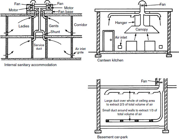
Basement car-parks require at least six air changes per hour and at exits and ramps where queuing occurs, local ventilation of at least 10 air changes per hour. Duplicate fans should be provided with a fan failure automatic change-over.
Fan-assisted ventilation systems supplying external air to habitable rooms must have a facility to pre-heat the air. They must also have control over the amount of air extracted, otherwise there will be excessive heat loss. A mechanical inlet and mechanical extract system can be used to regulate and balance supply and emission of air by designing the duct size and fan rating specifically for the situation.
Air may be extracted through specially made light fittings. These permit the heat-enhanced air to be recirculated back to the heating unit. This not only provides a simple form of energy recovery, but also improves the light output by about 10%. With any form of recirculated air ventilation system, the ratio of fresh to recirculated air should be at least 1:3. i.e. min. 25% fresh, max. 75% recirculated.
In large buildings where smoking is not permitted, such as a theatre, a downward air distribution system may be used. This provides a uniform supply of warm filtered air.
Ductwork in all systems should be insulated to prevent heat losses from processed air and to prevent surface condensation.

Profile – generally circular, square or rectangular but may be oval. For efficient distribution of air, the uniformity of circular ducting is preferred for the following reasons:
less opportunity for turbulence
less resistance to friction
inherent rigidity
lower heat losses or gains
sound transfer generally less
less potential for air leakage
Where space is restricted under floors or in suspended ceilings, rectangular ducting of high-aspect ratio may be required for practical reasons (aspect ratio and conversion from circular to square or rectangular equivalent size is explained on pages 266 to 268). Square or rectangular ducting direction changes are more easily formed than with circular sections.

Galvanised sheet steel is the most common material used for ventilation and air-conditioning ducting. Factory prefabricated sections are site jointed by bolted steel angle flanges with a rubber sealing gasket; the rigid angles can also function as suspended bracket fixings. Sleeve jointing with pop-rivets and tape sealant is also used with smaller profile sections.
In addition to galvanised steel, aluminium may be used in smaller profiles or externally in non-corrosive atmospheres. Copper or stainless steel is used where the ducting forms a feature, e.g. a cooker hood. Polypropylene and uPVC piping is suitable in short lengths and small diameters, mainly for domestic applications such as extract fan extensions. Plastic materials have limitations where performance in fire is a consideration.

Apart from standard plastic pipe profiles (100 and 150mm nominal diameter drainage pipes), most ducting is factory produced to the designer’s specification. It is unrealistic for sheet metal fabricators to produce standard sections due to unknown demand and the space requirement for storage.
Flexible ducts are useful for short connections from air distribution boxes or plenums to several diffusers within close proximity. They are also useful for correcting misalignments and for convenient connections to fan housings and terminals. Flexible connections to fans will help to reduce vibration and sound. Flexible ducting is produced in corrugations made up in a concertina format from thin sheet aluminium or from spirally wound steel-reinforced fabric. Lengths should be limited to as short as possible, as the concertina effect will impede air flow and create noise. Also, flexible ducting is more likely to suffer damage and leakage. Jointing is by taped sleeve and jubilee clip.
Propeller fan – does not create much air pressure and has limited effect in ductwork. Ideal for use at air openings in windows and walls.
Axial flow fan – can develop high pressure and is used for moving air through long sections of ductwork. The fan is integral with the run of ducting and does not require a base.
Bifurcated axial flow fan – used for moving hot gases, e.g. flue gases, and greasy air from commercial cooker hoods.
Cross-flow or tangential fan – used in fan convector units.
Centrifugal fan – can produce high pressure and has the capacity for large volumes of air. Most suited to larger installations such as air-conditioning systems. It may have one or two inlets. Various forms of impeller can be selected depending on the air condition. Variable impellers and pulley ratios from the detached drive motor make this the most versatile of fans.

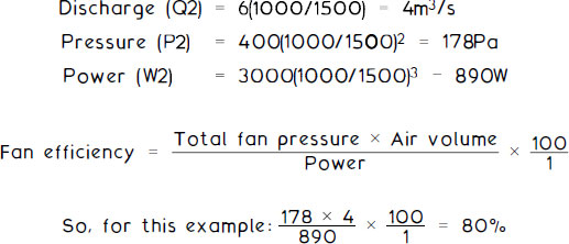
Fan performance depends very much on characteristics such as type and configuration of components. Given a standard set of criteria against which a fan’s performance is measured (i.e. 20°C dry bulb temperature, 101·325kPa (1013mb) atmospheric pressure, 50% relative humidity and 1·2kg/m3 air density), any variation in performance can be predicted according to the following fan laws:
Discharge (volumetric air flow) varies directly with the fan speed.

Fan pressure is proportional to the fan speed squared.
Fan power is proportional to the fan speed cubed.
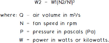
E.g. a mechanical ventilation system has the following fan characteristics:
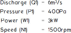
If the fan speed is reduced to 1000rpm, the revised performance data will apply:
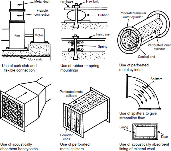
Fans and air turbulence can be a significant noise source in air distribution systems. System accessories and fittings such as ductwork material, grilles/diffusers, mixing boxes, tee junctions and bends can compound the effect of dynamic air. Ducts of large surface area may need to be stiffened to prevent reverberation.
Fans may be mounted on a concrete base, with either cork, rubber or fibre pad inserts. Strong springs are an alternative. Duct connections to a fan should have a flexible adaptor of reinforced PVC.
Sound attenuation in ducting can be achieved by continuously lining the duct with a fire-resistant, sound-absorbing material. Where this is impractical, strategically located attenuators/silencers composed of perforated metal inserts or a honeycomb of sound-absorbent material can be very effective. These have a dual function as system sound absorbers and as absorbers of airborne sound transmission from adjacent rooms sharing the ventilation system.
To prevent air impacting at bends, a streamlining effect can be achieved by fixing vanes or splitters to give the air direction.
Cell or panel – flat or in a vee formation to increase the surface contact area. Available in dry or wet (viscous) composition in disposable format for simple fitting within the ductwork. A rigid outer frame is necessary to prevent flanking leakage of dirty air. Dry filters can be vacuum cleaned to extend their life, but in time will be replaced. The viscous filter is coated with an odourless, non-toxic, non-flammable oil. These can be cleaned in hot, soapy water and recoated with oil.
Absolute – a type of dry cell filter produced from dense glass paper. The paper is folded into deep pleats to create a series of vee formations arranged parallel to the air flow to increase surface contact. Some manufacturers apply cardboard or thin aluminium interleaves to support the glass paper and to channel the air through the filter depth.
Bag – a form of filtration material providing a large air contact area. When the fan is inactive the bag will hang limply unless wire reinforced. It will resume a horizontal profile during normal system operation. Fabric bags can be washed periodically and replaced.
Roller – operated manually or by pressure-sensitive switch. As the filter becomes less efficient, resistance to air flow increases. The pressure effects a detector which engages a motor to bring down clean fabric from the top spool. Several perforated rollers can be used to vee format and increase the fabric contact area.
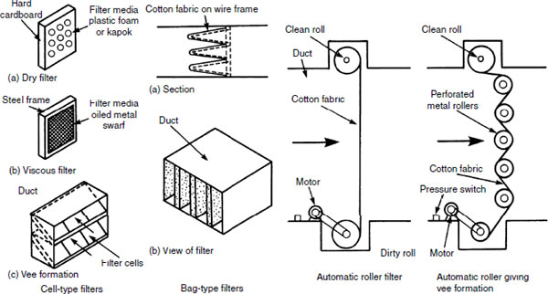
Viscous – these have a high dust-retention capacity and are often specified for application to industrial situations. An improvement on the panel type has close-spaced corrugated metal plates continuously sprayed with oil. A rotating variation has filter plates hung from chains. The lower plates in the cycle pass through a bath of oil which removes attached particles and resurfaces the plates with clean oil.
Electrostatic unit – this has an ionising area which gives suspended dust particles a positive electrostatic charge. These are conveyed in the air stream through metal plates which are alternately charged positive and earthed negative. Positively charged particles are repelled by the positive plates and attracted to the negative plates. The negative plates can also be coated with a thin layer of oil or gel for greater retention of dust. The unit can have supplementary, preliminary and final filters as shown below, giving an overall efficiency of about 99%.

Activated carbon – otherwise known as activated charcoal. A disposable filter composed of carbon particles resembling pieces of coconut shell and arranged to provide a large surface contact area. A glass fibre matting is often used to contain the carbon shells. This type of filter is used specifically in commercial cooker hoods and in other greasy, odorous atmospheres, as the carbon is extremely absorbent. The attraction between hot, greasy fumes and carbon is termed adsorption. Activated carbon filters are disposable and must be easily accessible for inspection and replacement.
Typical application –

Low-velocity Air Flow in Ducts
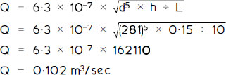
Simple ducted air systems, typical of those serving internal WCs and bathrooms, operate at relatively low air velocity with little frictional resistance or pressure drop. In these situations the relationship between air flow and duct diameter can be expressed as:
To determine duct diameter from design input data, the formula is represented:
![]()
E.g. A 10m-long ventilation duct is required to provide air at 0·10m3/sec at a pressure drop of 0·15mm wg.
To check that the calculated diameter of 281mm correlates with the given flow rate (Q) of 0·10m3/sec:
Diffusers – these vary considerably in design from standard manufactured slatted grilles to purpose-made hi-tech profiled shapes and forms compatible with modern interiors. The principal objective of air distribution and throw must not be lost in these designs.
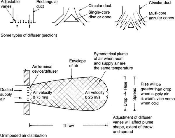
Coanda effect – diffuser location must be selected to avoid unwanted draughts, air delivery impacting on beams, columns and other air deliveries. Where structural elements are adjacent, such as a wall and ceiling, the air delivery may become entrained and drawn to the adjacent surface. This can be advantageous as the plume of air throw, although distorted, may extend to run down the far wall as well.

Location, type and size of supply air diffuser or grille will affect the way air is distributed within a room. Air temperature across the extremes of chilled to heated will also affect the air trajectory and pattern (see previous page).

Linear grille – spread control in one plane.
Modular grille – spread control in two planes.
Principle – fan-directed warm air blown across an external door opening as a barrier against cold outside air entering. Fan power must be sufficient to direct air from the top of the opening to the floor, although air direction can be horizontal. An alternative specifically for food stores and restaurants, uses ambient air to create air turbulence to prevent flying insects from entering a building.
Applications include frequently accessed buildings, e.g.
Shop openings/entrances
Workshop entrances
Public buildings
Aeroplane hangars
Restaurants
In less frequently used buildings an air curtain can be effected by a micro-switch fitted between door and frame.
Typical design data:
Discharge air temperature < 50°C
Air velocity < 15m/s
Air volume 3 to 6m3/s per m of opening width
Air jets angled 25° to 45° against external air
E.g.
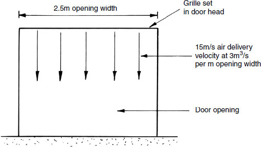
Air volume = 3m3/s for a 2.5m-wide opening = 7.5m3/s
Delivery ÷ velocity = 7.5m3/s ÷ 15m/s = 0.5m2 grille area
Grille will be 2.5m long (door-opening width) x 0.2m. i.e. 0.5m2
Ventilation Design – Air Velocity
Air velocity within a room or workplace should be between 0·15 and 0·50m/s, depending on the amount of activity. Sedentary tasks such as desk work will fall into the range of 0·15 to 0·30m/s, while more active assembly work, shop work and manufacturing, between 0·30 and 0·50m/s. These figures are designed to provide a feeling of freshness, to relieve stagnation without noise distraction from air movement equipment.
Conveyance of air and discharge through ducting and outlet diffusers will produce some noise. This should not be distracting and must be maintained at an unobtrusive level. As the extent of occupancy activity and/or machinery and equipment noise increases, so may the ducted air velocity, as background noise will render sound from air movement unnoticeable. For design purposes, the greater the ducted air velocity, the smaller the duct size and the less space consuming the ducting. However, some regard must be made for acceptable ducted air noise levels and the following table provides some guidance:
Situation |
Ducted air velocity (m/s) |
|---|---|
Very quiet, e.g. sound studio, library, study, operating theatre |
1·5–2·5 |
Fairly quiet, e.g. private office, habitable room, hospital ward |
2·5–4·0 |
Less quiet, e.g. shop, restaurant, classroom, general office |
4·0–5·5 |
Non-critical, e.g. gym, warehouse, factory, department store |
5·5–7·5 |
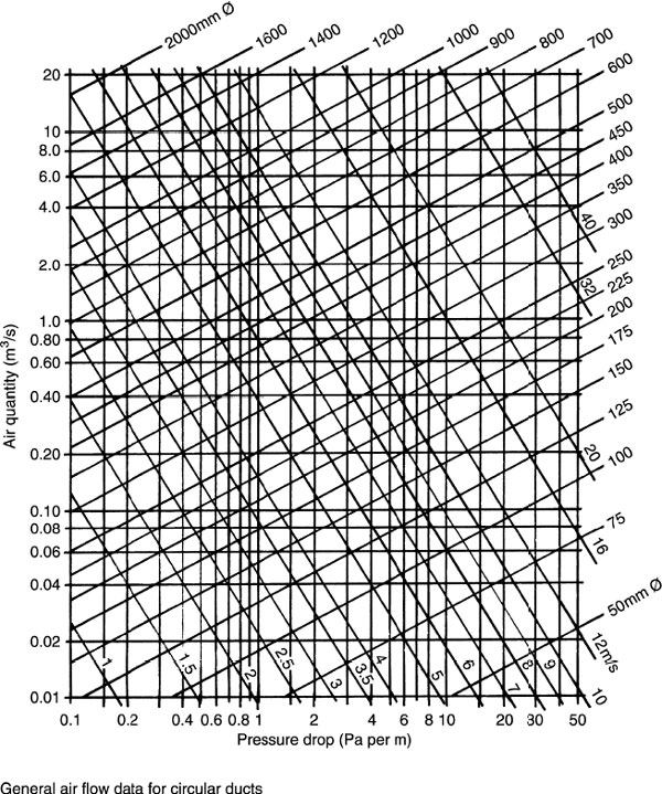
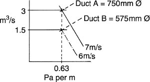
Ventilation Design – Duct Sizing Chart
Estimation of duct size and fan rating can be achieved by simple calculations and application to design charts. The example below is a graphical representation of the quantity of air (m3/s), friction or pressure reduction (N/m2 per m) or (Pa per m) and air velocity (m/s) in circular ductwork. Conversion to equivalent size square or rectangular ductwork is shown on pages 266–268.
Ventilation Design – Air Quantity
For mechanical supply and extract systems, the air volume flow rate or quantity of air can be calculated from the following formula:
![]()
Air changes per hour can be obtained from appropriate legislative standards for the situation or the guidance given on pages 237 and 238.
E.g.

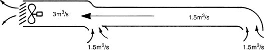
The ducted extract air system shown is a simple straight run, with duct A effectively 8m long and duct B effectively 16m long. Where additional bends, tees, offsets and other resistances to air flow occur, a nominal percentage increase should be added to the actual duct length. Some design manuals include ‘k’ factors for these deviations and an example is shown on pages 269 and 270.
For the example given:
![]()
Disposition of extract grilles and room function will determine the quantity of air removed through each grille and associated duct. In this example the grilles are taken to be equally disposed, therefore each extracts 1·5m3/s. Duct A therefore must have capacity for 3m3/s and duct B, 1·5m3/s.
There are several methods which may be used to establish ventilation duct sizes, each having its own priority. The following shows three of the more popular, as applied to the design chart on page 262.
Equal velocity – applied mainly to simple systems where the same air velocity is used throughout. For example, selected velocity is 7m/s (see page 261), therefore the design chart indicates:

Velocity reduction – air velocity is selected for the main section of ductwork and reduced for each branch. For example, selected air velocities for ducts A and B are 8m/s and 5m/s respectively:

Equal friction/constant pressure drop – air velocity is selected for the main section of ductwork. From this, the friction is determined and the same figure applied to all other sections. For example, selected air velocity through duct A is 7m/s:
Ventilation Design – System and Fan Characteristics
Using the example on page 263 with the equal velocity method of duct sizing shown on page 264, the fan will be required to extract 3m3 of air per second at a pressure of:
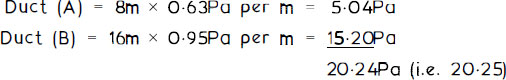
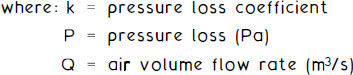
System pressure loss is calculated from: k = P/Q2
Therefore: k = 20·25/32 = 2·25
Using this coefficient, the system characteristic curve may be drawn between the operating air volume flow rate of 3m3/s down to a nominal low operating figure of, say, 0·5m3/s. By substituting figures in this range in the above transposed formula, P = k × Q2, we have:
P = 2·25 × (0·5)2 = 0·56Pa |
[0·5m3/s @ 0·56Pa] |
P = 2·25 × (1·0)2 = 2·25Pa |
[1·0m3/s @ 2·25Pa] |
P = 2·25 × (1·5)2 = 5·06Pa |
[1·5m3/s @ 5·06Pa] |
P = 2·25 × (2·0)2 = 9·00Pa |
[2·0m3/s @ 9·00Pa] |
P = 2·25 × (2·5)2 = 14·06Pa |
[2·5m3/s @ 14·06Pa] |
P = 2·25 × (3·0)2 = 20·25Pa |
[3·0m3/s @ 20·25Pa] |
Plotting these figures graphically against fan manufacturers’ data will provide an indication of the most suitable fan for the situation:

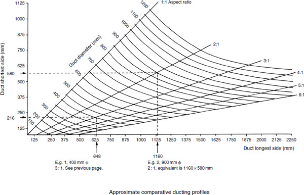
Ventilation Design – Duct Conversion
Some ventilation design manuals limit data presentation to circular profile ductwork only. It is often more convenient for manufacturers and installers if square or rectangular ductwork can be used. This is particularly apparent where a high-aspect ratio profile will allow ducting to be accommodated in depth-restricted spaces such as suspended ceilings and raised floors.
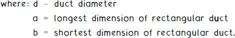
Aspect ratio:

The numerical relationship between dimension a to b. Square = 1:1.
Conversion of circular ductwork to square or rectangular (or vice versa) using the equal velocity of flow formula:
![]()
E.g. a 400mm diameter duct to be converted to a rectangular profile of aspect ratio 3:1.
![]()
Substituting in the above formula:
![]()
Therefore:
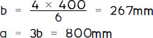
For equal volume of flow and pressure drop there are two possible formulae:
Notes: |
0.2 represents the fifth root of data in brackets. |
Formulae assume identical coefficient of friction occurs between circular and rectangular ducts, i.e. same material used. |
E.g. circular duct of 400mm diameter to be converted to rectangular having an aspect ratio of 3:1 . Therefore, a = 3b.
Substituting in formula 1:
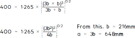
Substituting in formula 2:

See next page for a simplified graphical conversion.
Note: A circular duct has diameter equivalent to the side of a square duct multiplied by 1.1.
Most ducting is sized using the same pressure drop or pressure loss per metre length. Larger ducting in a ventilation system will require a higher velocity to maintain a pressure drop equivalent to the smaller distribution ducting that it serves. The higher velocity will generate some increase in air movement noise, but this is not usually a problem as larger ducting is generally remote from occupied areas.
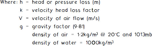
There are many scientific applications to frictional or pressure losses created as air flows through ductwork. One of the most established is derived from Bernoulli’s theorem of energy loss and gain as applied to fluid and air flow physics. Interpretation by formula:
![]()
‘k’ factors have been calculated by experimentation using different ductwork materials. They will also vary depending on the nature of fittings (i.e. tees, bends, etc.), the profile, extent of direction change, effect of dampers and other restrictions to air flow. Lists of these factors are extensive and can be found in ventilation design manuals. The following is provided as a generalisation of some mid-range values for illustration purposes only:
Duct fitting |
Typical ‘k’ factor |
|---|---|
Radiused bend (90°) |
0·30 |
Mitred bend (90°) |
1·25 |
Branch (tee) piece (90°) |
0·40–1·70* |
Branch (tee) piece (45°) |
0·12–0·80* |
Reductions (abrupt) |
0·25 |
Reductions (gradual) |
0·04 |
Enlargements (abrupt) |
0·35 |
Enlargements (gradual) |
0·20 |
Obstructions (louvres/diffusers) |
1·50 |
Obstructions (wire mesh) |
0·40 |
Obstructions (dampers) |
0·20–0·50† |
Notes:
*Varies with area ratios of main duct to branch duct.
†Varies depending on extent of opening.
Resistances to Air Flow – Calculations
E.g. Calculate the pressure loss in a 10m length of 400mm-diameter ductwork containing four 90° radiused bends. Velocity of air flow is 5m/s.
![]()
Bernoulli’s formula:
From the duct sizing chart on page 262, the pressure loss for a 400mm diameter duct at 5m/s is approximately 0.8Pa per metre.
For 10m of ductwork = 10 × 0·8 = 8Pa.
Total pressure loss = 18Pa + 8Pa = 26Pa.
An alternative to the duct sizing chart for finding air flow resistance is the application of another established fluid and air flow theorem attributed to D’Arcy. This can be used for pipe sizing as well as for sizing small ducts.
D’Arcy’s formula:
![]()

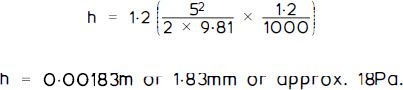
Using the above example of a 10m length of 400mm (0.4m) ductwork conveying air at 5m/s:
![]()
h = 0·0008 m or 0·8 mm or approx. 8 Pa.
Ventilation System Heating Load
When designing ventilation systems, provision must be made for the displacement of heat energy resulting from the movement of air. This is necessary for maintenance of the building or room ambient temperature. Also, to prevent cold draughts and condensation.
Cold supply air is pre-heated to discharge at the same temperature as the design air temperature for the room served. This will have no real effect on any separate heating system and can be regulated independently by a control thermostat. The following formula can be used to establish the ducted air heater rating in kW, relative to design temperature parameters:
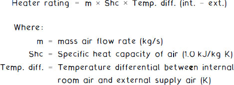
Air flow rate by volume (Q) is calculated in m3/s. To convert this to mass air flow rate in kg/s, the volume rate is multiplied by air density (ρ) of 1.2kg/m3.
Therefore:
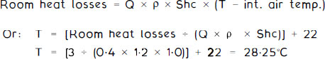
Heater rating = Q × ρ ρ Shc × Temp. diff. (int. − ext.)
For example, a room with total fabric and infiltration heat losses of 3kW (see method of calculation on page 189), with air supply and temperature design factors as given below:

![]()
Therefore if the ducted air is required to supply all heating needs, then 12.48kW is added to the room losses of 3kW, bringing the total heat input to 15.48kW. If the ducted air system is to provide for the design room heat loss of 3kW, the discharge air temperature (T) can be found by rewriting the formula: