Chapter 3. The Arduino Platform
Arduino is composed of two major parts: the Arduino board, which is the piece of hardware you work on when you build your objects; and the Arduino IDE, the piece of software you run on your computer. You use the IDE to create a sketch (a little computer program) that you upload to the Arduino board. The sketch tells the board what to do.
Not too long ago, working on hardware meant building circuits from scratch, using hundreds of different components with strange names like resistor, capacitor, inductor, transistor, and so on.
Every circuit was “wired” to do one specific application, and making changes required you to cut wires, solder connections, and more.
With the appearance of digital technologies and microprocessors, these functions, which were once implemented with wires, were replaced by software programs.
Software is easier to modify than hardware. With a few keypresses, you can radically change the logic of a device and try two or three versions in the same amount of time that it would take you to solder a couple of resistors.
The Arduino Hardware
The Arduino board is a small microcontroller board, which is a small circuit (the board) that contains a whole computer on a small chip (the microcontroller). This computer is at least a thousand times less powerful than the MacBook I’m using to write this, but it’s a lot cheaper and very useful to build interesting devices. Look at the Arduino board: you’ll see a black chip with 28 “legs”—that chip is the ATmega168, the heart of your board.
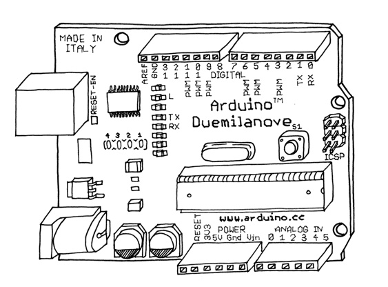
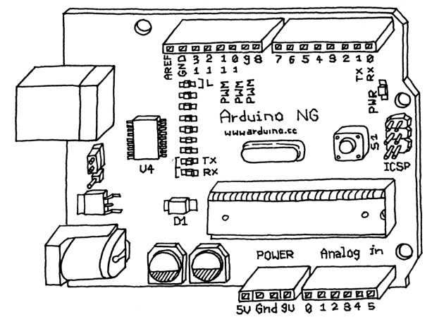
We (the Arduino team) have placed on this board all the components that are required for this microcontroller to work properly and to communicate with your computer. There are many versions of this board; the one we’ll use throughout this book is the Arduino Duemilanove, which is the simplest one to use and the best one for learning on. However, these instructions apply to earlier versions of the board, including the more recent Arduino Diecimila and the older Arduino NG. Figure 3-1 shows the Arduino Duemilanove; Figure 3-2 shows the Arduino NG.
In those illustrations, you see the Arduino board. At first, all those connectors might be a little confusing. Here is an explanation of what every element of the board does:
14 Digital IO pins (pins 0–13)
These can be inputs or outputs, which is specified by the sketch you create in the IDE.
6 Analogue In pins (pins 0–5)
These dedicated analogue input pins take analogue values (i.e., voltage readings from a sensor) and convert them into a number between 0 and 1023.
6 Analogue Out pins (pins 3, 5, 6, 9, 10, and 11)
These are actually six of the digital pins that can be reprogrammed for analogue output using the sketch you create in the IDE.
The board can be powered from your computer’s USB port, most USB chargers, or an AC adapter (9 volts recommended, 2.1mm barrel tip, center positive). If there is no power supply plugged into the power socket, the power will come from the USB board, but as soon as you plug a power supply, the board will automatically use it.
The Software (IDE)
The IDE (Integrated Development Environment) is a special program running on your computer that allows you to write sketches for the Arduino board in a simple language modeled after the Processing (www.processing.org) language. The magic happens when you press the button that uploads the sketch to the board: the code that you have written is translated into the C language (which is generally quite hard for a beginner to use), and is passed to the avr-gcc compiler, an important piece of open source software that makes the final translation into the language understood by the microcontroller. This last step is quite important, because it’s where Arduino makes your life simple by hiding away as much as possible of the complexities of programming microcontrollers.
The programming cycle on Arduino is basically as follows:
Plug your board into a USB port on your computer.
Write a sketch that will bring the board to life.
Upload this sketch to the board through the USB connection and wait a couple of seconds for the board to restart.
The board executes the sketch that you wrote.
Note
NOTE: Installing Arduino on Linux is somewhat complicated at the time of this writing. See www.arduino.cc/playground/Learning/Linux for complete instructions.
Installing Arduino on Your Computer
To program the Arduino board, you must first download the development environment (the IDE) from here: www.arduino.cc/en/Main/Software. Choose the right version for your operating system.
Download the file and double-click on it to uncompress it; this will create a folder named arduino-[version], such as arduino-0012. Drag that folder to wherever you would like it to be: your desktop, your /Applications folder (on a Mac), or your C:Program Files folder (on Windows). Now whenever you want to run the Arduino IDE, you’ll open up the arduino folder, and double-click the Arduino icon. Don’t do this just yet, though; there is one more step to perform.
Note
NOTE: If you have any trouble running the Arduino IDE, see Chapter 7, Troubleshooting.
Now you must install the drivers that allow your computer to talk to your board through the USB port.
Installing Drivers: Macintosh
Look for the Drivers folder inside the arduino-0012 folder and double-click the file called FTDIUSBSerialDriver_x_x_x.dmg (x_x_x will be replaced with the version number of the driver, for example FTDIUSBSerialDriver_v2_2_9_Intel.dmg). Double-click the .dmg file to mount it.
Note
Note: If you are using an Intel-based Mac, such as a MacBook, MacBook Pro, MacBook Air, Mac Pro, or Intel-based Mac Mini or iMac, be sure to install the driver with “Intel” in its name, as in FTDIUSBSerialDriver_v2_2_9_Intel.dmg. If you aren’t using an Intel-based Mac, install the one without “Intel” in its name.
Next, install the software from the FTDIUSBSerialDriver package by double-clicking on it. Follow the instructions provided by the installer and type the password of an administrative user if asked. At the end of this process, restart your machine to make sure that the drivers are properly loaded. Now plug the board into your computer. The PWR light on the board should come on and the yellow LED labelled “L” should start blinking. If not, see Chapter 7, Troubleshooting.
Installing Drivers: Windows
Plug the Arduino board into the computer; when the Found New Hardware Wizard window comes up, Windows will first try to find the driver on the Windows Update site.
Windows XP will ask you whether to check Windows Update; if you don’t want to use Windows Update, select the “No, not at this time” option and click Next.
On the next screen, choose “Install from a list or specific location” and click Next.
Check the box labeled “Include this location in the search”, click Browse, select the folder where you installed Arduino, and select the DriversFTDI USB Drivers folder as the location. Click OK, and Next.
Windows Vista will first attempt to find the driver on Windows Update; if that fails, you can instruct it to look in the DriversFTDI USB Drivers folder.
You’ll go through this procedure twice, because the computer first installs the low-level driver, then installs a piece of code that makes the board look like a serial port to the computer.
Once the drivers are installed, you can launch the Arduino IDE and start using Arduino.
Next, you must figure out which serial port is assigned to your Arduino board—you’ll need that information to program it later. The instructions for getting this information are in the following sections.
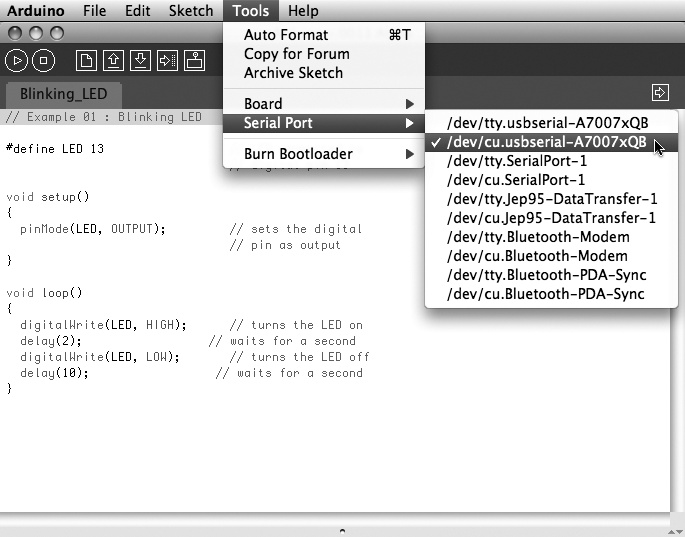
Port Identification: Macintosh
From the Tools menu in the Arduino IDE, select “Serial Port” and select the port that begins with /dev/cu.usbserial-; this is the name that your computer uses to refer to the Arduino board. Figure 3-3 shows the list of ports.
Port Identification: Windows
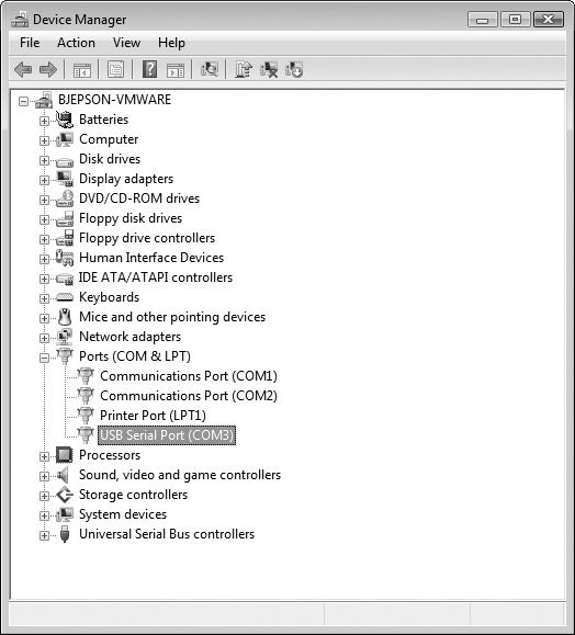
On Windows, the process is a bit more complicated–at least at the beginning. Open the Device Manager by clicking the Start menu, right-clicking on Computer (Vista) or My Computer (XP), and choosing Properties. On Windows XP, click Hardware and choose Device Manager. On Vista, click Device Manager (it appears in the list of tasks on the left of the window).
Look for the Arduino device in the list under "Ports (COM & LPT)”. The Arduino will appear as a USB Serial Port and will have a name like COM3, as shown in Figure 3-4.
Note
Note: On some Windows machines, the COM port has a number greater than 9; this numbering creates some problems when Arduino is trying to communicate with it. See Chapter 7, Troubleshooting for help on this problem.
Once you’ve figured out the COM port assignment, you can select that port from the Tools > Serial Port menu in the Arduino IDE.
Now the Arduino development environment can talk to the Arduino board and program it.