


IBM XIV Storage System
This chapter addresses specific considerations for using the IBM XIV® Storage System as storage for IBM ProtecTIER servers.
This chapter describes the following topics:
•XIV Storage System hardware overview
•Fibre Channel switch cabling and zoning and zoning configuration for maximum performance with an XIV Storage System
10.1 XIV Storage System hardware
Figure 10-1 shows an example of the IBM XIV Storage System hardware and
supported modules.
supported modules.

Figure 10-1 XIV Storage System hardware
XIV Storage System supports configurations of 6, 9, 10, 11, 12 13, 14, or 15 modules (Table 10-1):
•Modules 1 - 3 and 10 - 15 are disks only and are called data modules.
•Modules 4 - 9 have disks and host interfaces and are called interface modules.
Table 10-1 Configurations of modules
|
Number of modules
|
6
|
9
|
10
|
11
|
12
|
13
|
14
|
15
|
|
Interface Module 9 state
|
Empty
|
Disabled
|
Disabled
|
Enabled
|
Enabled
|
Enabled
|
Enabled
|
Enabled
|
|
Interface Module 8 state
|
Empty
|
Enabled
|
Enabled
|
Enabled
|
Enabled
|
Enabled
|
Enabled
|
Enabled
|
|
Interface Module 7 state
|
Empty
|
Enabled
|
Enabled
|
Enabled
|
Enabled
|
Enabled
|
Enabled
|
Enabled
|
|
Interface Module 6 state
|
Disabled
|
Disabled
|
Disabled
|
Disabled
|
Enabled
|
Enabled
|
Enabled
|
Enabled
|
|
Interface Module 5 state
|
Enabled
|
Enabled
|
Enabled
|
Enabled
|
Enabled
|
Enabled
|
Enabled
|
Enabled
|
|
Interface Module 4 state
|
Enabled
|
Enabled
|
Enabled
|
Enabled
|
Enabled
|
Enabled
|
Enabled
|
Enabled
|
|
FC ports
|
8
|
16
|
16
|
20
|
20
|
24
|
24
|
24
|
|
Usable capacity (1 / 2 / 3 / 4 / 6 TB)
|
28 TB
55 TB
84 TB
112 TB
169 TB
|
44 TB
88 TB
132 TB
177 TB
267 TB
|
51 TB
102 TB
154 TB
207 TB
311 TB
|
56 TB
111 TB
168 TB
225 TB
338 TB
|
63 TB
125 TB
190 TB
254 TB
382 TB
|
67TB
134 TB
203 TB
272 TB
409 TB
|
75 TB
149 TB
225 TB
301 TB
453 TB
|
81 TB
161 TB
243 TB
325 TB
489 TB
|
10.2 Fibre Channel switch cabling and zoning
For maximum performance with an XIV Storage System, connect all available XIV Storage System Interface Modules and use all of the back-end ProtecTier ports. For redundancy, connect Fibre Channel cables from the ProtecTIER server to two Fibre Channel switched fabrics.
If a single XIV Storage System is being connected, each Fibre Channel switched fabric must have six available ports for Fibre Channel cable attachment to the XIV Storage System. Generally, two connections are used for each interface module in XIV Storage System. Typically, XIV Storage System Interface Module port 1 is used for Fibre Channel switch 1, and port 3 is used for switch 2 (Figure 10-2).

Figure 10-2 Cable diagram for connecting a TS7650G to XIV Storage System
When you use a partially configured XIV Storage System rack, see Figure 10-2 to locate the available FC ports.
10.2.1 Zoning configuration
For each ProtecTIER disk attachment port, multiple XIV Storage System host ports are configured into separate isolated zone pairing in a 1:1 manner:
•All XIV Storage System Interface Modules on port 1 are zoned to the ProtecTIER host bus adapter (HBA) in slot 6, port 1 and HBA in slot 7, port 1.
•All XIV Storage System Interface Modules in port 3 are zoned to the ProtecTIER HBA in slot 6, port 2 and HBA in slot 7, port 2.
|
Information: The suggested way is to connect port 1 and port 3 of the XIV Storage System Interface Modules because they are predefined for host I/O. Other ports might be predefined for XIV Storage System replication. Also, ports 1 and 3 are distributed across the XIV internal dual-port adapters. So, using ports 1 and 3 minimizes administrative effect and ensures protection against an adapter failure of XIV I/O modules.
|
Each Interface Module in the XIV Storage System has a connection with both ProtecTIER HBAs. A typical ProtecTIER configuration uses 1:1 zoning (one initiator and one target in each zone) to create zones. These zones connect a single ProtecTIER server with a
15 module XIV Storage System with all six Interface Modules (Example 10-1).
15 module XIV Storage System with all six Interface Modules (Example 10-1).
Example 10-1 Zoning example for an XIV Storage System attachment
Switch 1:
Zone 01: PT_S6P1, XIV_Module4Port1
Zone 02: PT_S6P1, XIV_Module6Port1
Zone 03: PT_S6P1, XIV_Module8Port1
Zone 04: PT_S7P1, XIV_Module5Port1
Zone 05: PT_S7P1, XIV_Module7Port1
Zone 06: PT_S7P1, XIV_Module9Port1
Zone 02: PT_S6P1, XIV_Module6Port1
Zone 03: PT_S6P1, XIV_Module8Port1
Zone 04: PT_S7P1, XIV_Module5Port1
Zone 05: PT_S7P1, XIV_Module7Port1
Zone 06: PT_S7P1, XIV_Module9Port1
Switch 02:
Zone 01: PT_S6P2, XIV_Module4Port3
Zone 02: PT_S6P2, XIV_Module6Port3
Zone 03: PT_S6P2, XIV_Module8Port3
Zone 04: PT_S7P2, XIV_Module5Port3
Zone 04: PT_S7P2, XIV_Module5Port3
Zone 05: PT_S7P2, XIV_Module7Port3
Zone 06: PT_S7P2, XIV_Module9Port3
This example has the following characteristics:
•Each ProtecTIER back-end host bus adapter (HBA) port sees three XIV Storage System Interface Modules.
•Each XIV Storage System Interface Module is connected redundantly to two separate ProtecTIER back-end HBA ports.
•There are 12 paths (4 x 3) to one volume from a single ProtecTIER server.
10.3 Configuring XIV Storage System for ProtecTIER server
An IBM Service Support Representative (SSR) uses the ProtecTIER Capacity Planning tool to size the ProtecTIER repository metadata and user data. Capacity planning varies, because it depends heavily on your type of data and expected deduplication ratio.
The planning tool output includes the detailed information about all volume sizes and capacities for your specific ProtecTIER installation. If you do not have this information, contact your IBM SSR to get it.
|
Tip: When you calculate the required size of the repository for ProtecTIER, always account for three factors:
•Factoring ratio (can be estimated using the IBM ProtecTIER Performance Calculator)
•Throughput
•Size of the repository
The factoring ratio and the size of the repository directly impact the size of the metadata volumes; the bigger these values are, the bigger the required metadata volumes will be, while higher throughput will require a larger number of metadata volumes. These three factors must be considered for the initial installation, always accounting for the future growth of the business.
|
You must configure the XIV Storage System before the ProtecTIER system is installed by an SSR. To configure the system, complete the following steps:
1. Configure an XIV Storage System for the ProtecTIER system. Set the snapshot space to zero because creating snapshots on XIV Storage System is not supported by a ProtecTIER server.
2. Set up volumes in the XIV Storage System with the ProtecTIER Capacity Planning tool and the Create repository planning wizard output. Starting with ProtecTIER V3.2.0, you can select XIV MD Device 8 +8 for the MD RAID Configuration from the ProtecTIER Manager when you are using the Create repository planning wizard.
The ProtecTIER Capacity Planning tool output gives you the metadata volume size and the size of the 32 user data volumes. Also configure a Quorum volume with a minimum of 1 GB, or 17 GB for XIV Storage System because that is the smallest volume size that can be created, in case the solution needs more ProtecTIER servers in the future.
|
Important: Your IBM SSR can use the Capacity Magic tool to calculate the size of the XIV volumes accurately to ensure that you get the expected volume sizes.
|
3. Map the volumes to the ProtecTIER server or ProtecTIER cluster.
Example of configuring an XIV Storage System
If you want to set up a ProtecTIER environment with a 79 TB XIV Storage System and a deduplication factoring ratio of 12, use the following volumes sizes:
•2 x 1571 GB volumes for metadata: Make these volumes equal to each other, and nearest to the XIV Storage System allocation size, in this case, 1583 (see Figure 10-4 on page 163).
•1 x 17 GB volume for Quorum (see Figure 10-5 on page 163): It must be 17 GB because that is the XIV Storage System minimum size.
•32 x <Remaining Pool Space available>, which is 75440: Dividing 75440 by 32 means that user data LUNs on the XIV Storage System should be 2357 GB each (see Figure 10-6 on page 164).
|
Memory totals: When you have an XIV Storage System Gen 3 full rack, you can have up to 243 TB of available space. With that configuration, and also if you have more than one XIV Storage System connected to the ProtecTIER server, you might need more than 32 LUNS. For the best performance, do not exceed the LUN size of 6 TB.
For example, two full racks equal 486 TB. Dividing this number by 6 (as in the 6 TB suggested LUN size), you need roughly 81 LUNs. Create the necessary metadata LUNs of the suggested size and the 6 TB LUNs for user data.
Always upgrade the firmware of your XIV Storage System to the current supported level. For more information, see Appendix B, “ProtecTIER compatibility” on page 457.
For XIV Storage System series, capacity, and connectivity details, see this web page:
|
As illustrated in the following examples, the XIV Storage System client GUI makes this calculation easy for you. Enter the number of volumes to create, then drag the slider to the right to fill the entire pool. The GUI automatically calculates the appropriate
equivalent amount.
equivalent amount.
Create a pool size for the capacity that you want to use for the ProtecTIER Deduplication Gateway with the XIV Storage System GUI, as shown in Figure 10-3. Normally, this would be 100% of the available space on the XIV. Create one single pool only; there is no benefit to having multiple pools.
|
Information: On older firmware levels of XIV, you might be required to have multiple pools to allocate all the space that you want to use with ProtecTIER. Besides a slightly increased administrative effect, there is no drawback to completing this action.
|

Figure 10-3 Creating a pool
|
Tip: Use a regular pool and zero the snapshot reserve space. Snapshots and thin provisioning are not supported when XIV Storage System is used with a
ProtecTIER server. |
Figure 10-4 shows the creation of the metadata volumes.
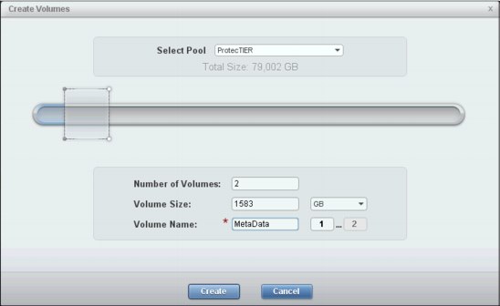
Figure 10-4 Creating metadata volumes
Figure 10-5 shows the creation of the quorum volume.

Figure 10-5 Creating a quorum volume
Figure 10-6 shows the creation of volumes for user data. The arrows show dragging the slider to use all of the pool. This action automatically calculates the appropriate size for all volumes.

Figure 10-6 Creating user data volumes
If you have a ProtecTIER cluster (two ProtecTIER servers in a high availability solution), complete the following steps:
1. Create a cluster group (Figure 10-7).

Figure 10-7 Creating a cluster group
2. Add a host that is defined for each node to that cluster group.
3. Create a cluster definition for the highly available ProtecTIER cluster (Figure 10-8).

Figure 10-8 Adding a cluster definition

Figure 10-9 Adding a host to the cluster

Figure 10-10 Adding a ProtecTIER host to a cluster
6. Find the worldwide port names (WWPNs) of the ProtecTIER servers. WWPNs can be found in the name server of the Fibre Channel switch. If zoning is in place, they are selectable from the menu. Alternatively, they can also be found in the basic input/output system (BIOS) of the HBA cards and then entered manually in to the XIV Storage System graphical user interface (GUI).
7. Add the WWPNs to the ProtecTIER servers (Figure 10-11).

Figure 10-11 Adding the WWPN of ProtecTIER server 1 to the cluster
Figure 10-12 shows the WWPNs that are added to the hosts.

Figure 10-12 ProtecTIER WWPNs added to host and cluster definitions
8. Map the volumes to the ProtecTIER cluster. In the XIV Storage System GUI, right-click the cluster name or on the host if you have only one ProtecTIER server, and select Modify LUN Mapping. Figure 10-13 shows you what the mapping view looks like.
|
Tip: If you have only one ProtecTIER server, map the volumes directly to the
ProtecTIER server. |

Figure 10-13 Mapping LUNs to the ProtecTIER cluster
..................Content has been hidden....................
You can't read the all page of ebook, please click here login for view all page.