


ProtecTIER replication
Information technology (IT) organizations that use an IBM ProtecTIER system with replication can easily expand the coverage of that replication to all of the applications in their environment. You can create replication policies to set rules for replicating data objects across ProtecTIER repositories. This chapter describes the purpose of replication and the enhanced features of the latest ProtecTIER code.
This chapter describes the procedures for replication deployment, including preinstallation steps, creation of the replication grid, and synchronization of the primary and secondary repositories. It also describes upgrading the existing system and enabling replication.
In addition, this chapter provides the principal rules and guidance of replication deployment for the ProtecTIER product in environments with Virtual Tape Library (VTL), and File System Interface (FSI). It also describes the concepts, procedures, and considerations that are related to optimizing replication performance, including the procedures to automate and script the daily operations.
This chapter primarily focuses on preferred practices for planning, configuration, operation, and testing of ProtecTIER native replication. The concept, detailed planning, and implementation of native replication is described in IBM TS7650 with ProtecTIER V3.4 User's Guide for VTL Systems, GA32-0922. This chapter describes the following topics:
21.1 ProtecTIER IP replication
The ProtecTIER IP replication function (Figure 21-1) provides a powerful tool that you can use to design robust disaster recovery architectures. You electronically place backup data into vaults with much less network bandwidth, therefore changing the paradigm of how data is taken off-site for safe keeping. The ProtecTIER IP replication feature can eliminate some of the expensive and labor-intensive handling, transport, and securing of the real tapes for disaster recovery purposes.

Figure 21-1 IP replication in a backup and recovery environment
Figure 21-1 illustrates how the ProtecTIER IP replication function can be used in a backup and recovery environment. This particular client uses this feature to replicate all of the virtual tapes in onsite PT_VTAPE_POOL off-site. It also backs up all backup application databases or catalogs to virtual tapes. These database backup virtual tapes are also replicated to Site B.
If a disaster occurs, this client can restore the backup server environment on Site B, which is connected to a ProtecTIER VTL. It contains the backup application database (catalog) together with all of the client backup files on virtual tapes in the PT_VTAPE_POOL pool.
21.2 Native replication
ProtecTIER native replication enables data replication capability across repositories, among ProtecTIER systems, which are connected to the wide area network (WAN). Because the ProtecTIER product deduplicates data before storing it, only the changes, or unique elements of data, are transferred to the DR site over the replication link. This feature can translate into substantial savings in the bandwidth that is needed for the replication TCP/IP link.
In early versions of ProtecTIER, the repository replication was handled by the disk array systems. Starting with Version 2.4, ProtecTIER introduced the function that is known as native replication, where the replication of deduplicated data became a function of ProtecTIER. Deduplicated data is replicated to a secondary ProtecTIER system through TCP/IP rather than relying on the back-end disk arrays and their associated infrastructure.
21.2.1 One-to-one replication
The initial replication design of ProtecTIER consisted of two ProtecTIER systems, with one system that is designated as the source and the other system that is designated as the target. The target system (or hub) was dedicated to receive incoming replicated data and was not eligible to take local backups.
21.2.2 Many-to-one replication
ProtecTIER Version 2.4 expanded the native replication functionality and introduced the many-to-one replication grid. Also known as spoke and hub, up to 12 source systems (spokes) can all replicate to a single target ProtecTIER system (hub) simultaneously. The hub system can provide DR functionality for one or more spokes concurrently, and the hub system can accept and deduplicate local backup data. The hub system cannot replicate outgoing data.
21.2.3 Many-to-many replication
ProtecTIER Version 3.1 built upon existing replication technology and introduced the many-to-many bidirectional replication grid. Up to four systems (all hubs) can be joined into a bidirectional replication grid and can accept and deduplicated local backup data, replicate data to up to three other ProtecTIER systems in the grid, and receive incoming replicated data from up to three other ProtecTIER systems in the grid.
21.2.4 VTL replication
VTL replication can be set up as one-to-one, many-to-one, and many-to-many. The ProtecTIER VTL service emulates traditional tape libraries. Your existing backup application can access virtual robots to move virtual cartridges between virtual slots and drives. The backup application perceives that the data is being stored on cartridges, although the ProtecTIER product stores data on a deduplicated disk repository. In a VTL replication scenario, data is replicated at the virtual tape cartridge level.
21.2.5 FSI replication
With FSI replication, up to eight ProtecTIER FSI systems can be included in the bidirectional replication group (Figure 21-2). Each FSI system can replicate deduplicated data to as many as three other remote ProtecTIER FSI systems. Data is replicated at the file system level.

Figure 21-2 FSI replication topology group
21.2.6 Replication grid
A replication grid is a logical set of repositories that can replicate from one repository to other repositories. A ProtecTIER system must be a member of a replication grid before the system is able to create replication policies.
All ProtecTIER systems are capable of replication. Different models of ProtecTIER systems, such as the TS7650G Gateway and TS7620 Appliance Express models, can be part of the same grid. You can have more than one replication topology group in the same grid. A grid can also contain various types of replication groups, such as groups of VTL and FSI. A single replication grid can include up to 24 ProtecTIER systems.
|
Important: A ProtecTIER system can be a member of only one replication grid in its lifetime. After a ProtecTIER system joins a grid, it is no longer eligible to join any other ProtecTIER replication grid.
|
21.2.7 Replication topology group
A replication topology group defines the relationship between ProtecTIER systems in a replication grid. A group includes many-to-one, many-to-many, and FSI groups. A replication grid can have multiple topology groups of various types, as shown in Figure 21-3.
|
Note: A ProtecTIER system can be a member of only one topology group at a time. A ProtecTIER system can move from one topology group to another in the same grid.
|

Figure 21-3 Multiple topology groups in a single replication grid.
21.3 Replication policies
The rules for replicating ProtecTIER data objects (VTL cartridges, and FSI file systems) are defined in replication policies. Replication policies for VTL and FSI data objects are defined on the ProtecTIER system.
When the backup application writes to a ProtecTIER data object (VTL cartridge or FSI file system) that is part of a replication policy, the ProtecTIER software conducts a check on the object and places it in the replication queue. For VTL cartridges the check includes determining the replication priority, for FSI file systems the replication policies do not have a priority option.
Data objects created in the primary site repository are read/write enabled so that the backup application at the primary site has full control of them and their content. Data objects replicated to the DR site are set in a read-only mode.
In VTL replication, only one cartridge instance can be in a library at the same time; all replicas are on the virtual shelf in the disaster recovery site repository.
|
Tip: At any time, you can override the default location of any VTL cartridge and manually move the replica from the virtual shelf to a library in the repository of the disaster
recovery site. |
Before replication occurs, the dirty bit technology system determines which data objects need to be replicated. Both the local and secondary sites hold synchronized data for each of their data objects. The destination site then references this synchronized data to determine which data (if any) should be transferred. The replication mechanism has two types of data to transfer:
Metadata Data that describes the actual data and carries all the information about it.
User data The actual backed up data.
A data object is marked as synced after its data finishes replicating from the primary to the secondary site. So, at the time of synchronization, the local objects and their remote replicas are identical. Before replication starts running, the system ensures that only unique new data is transferred over the TCP/IP link.
|
Attention: If you delete a data object in the source repository, then all the replicas are also deleted in the target repositories.
Network failure: If a network failure occurs during replication, the system continues to try, for up to seven consecutive days, to complete the replication tasks. After seven days, a replication error is logged and the replication tasks are no longer retried automatically by the system.
|
21.4 Visibility switching
Visibility switching is the automated process that transfers the visibility of a VTL cartridge from its master to its replica and vice versa. The visibility switching process is triggered by moving a cartridge (that is part of a replication policy) to the source library import/export slot. The cartridge then disappears from the import/export slot and appears at the destination library import/export slot, and at the source the cartridge is moved from the import/export slot to the shelf.
To move the cartridge back to the source library, the cartridge must be ejected to the shelf at the destination library. The cartridge then disappears from the destination library and reappears at the source import/export slot.
21.5 Principality
Principality is the privilege to write to a cartridge (set it to read/write mode). The principality of each cartridge belongs to only one repository in the grid. By default, the principality belongs to the repository where the cartridge was created. The cartridge metadata information includes the principality repository ID field.
Principality can be changed from one repository to another, by which the writing permissions are transferred from one repository to another. Principality can be changed in the following cases:
•During normal replication operation, from the repository where the cartridge was created to the DR repository, if the cartridge is 100% synced.
•During failback process, if the principality belongs to one of the following repositories:
– The DR repository
– The original primary repository, and this site is the destination for the failback.
– The original primary repository with the following exceptions:
• The original primary repository is out of the replication grid.
• The target for the failback is a repository that is defined as a replacement repository through the ProtecTIER repository replacement procedure.
21.6 Replication Manager
The ProtecTIER Replication Manager, also known as Grid Manager, is the part of the software that is used to remotely manage the replication configuration. From the Replication Manager, you can build and maintain the replication infrastructure and
repository relationships.
repository relationships.
The preferred practice is to designate the DR site system as the Replication Manager.
A possibility is to have a ProtecTIER Replication Manager (Grid Manager) installed in a node that is not one of the systems that the Grid Manager is managing. To have a dedicated host as a Grid Manager requires a request for product quotation (RPQ), which must be requested by your IBM marketing representative.
The ProtecTIER Replication Manager that is installed on a ProtecTIER node can manage only one grid with up to 24 repositories. If a dedicated server is chosen, and approved by the RPQ process, it can manage up to 64 grids with 256 repositories in each grid.
You must activate the Grid Manager function before you can add it to the list of known Grid Managers on the ProtecTIER Manager GUI, as shown in Figure 21-4 on page 368.

Figure 21-4 Designate ProtecTIER system as a ProtecTIER Replication Manager
To designate a ProtecTIER system as a Grid Manager, use the menu command (Figure 21-5):
ProtecTIER Configuration > Configure replication

Figure 21-5 Enable Replication Manager function
21.7 Initial synchronization
When a new ProtecTIER system is configured as a replication target (secondary) for an already existing ProtecTIER system (primary), it is necessary to synchronize the primary system with the secondary system.
A deployment of a second ProtecTIER server at a secondary (DR) site has an effect on the planning cycle because the first replication jobs use more bandwidth than required after deduplication takes effect. So, when you prepare for replication deployment, bandwidth is an important consideration.
During the planning cycle, the planners and engineers must consider the amount of nominal data that will be replicated, and the amount of dedicated bandwidth. It might be necessary to implement a replication policy that enables the first replication job to complete before the next backup activity begins.
|
Note: For the initial replication, you must arrange enough network bandwidth to account for the full nominal size of the data to be replicated.
|
Two methods can be used; both methods focus on gradually adding workload to the replication policies over time.
Gradual management of policies over time
This is the preferred method, whether you are deploying a new system or adding replication to an existing system. In this method, you add new replication policies over time, and manually ensure that the total daily volume of replicated data remains in the bandwidth limit. Replication policies with a gradual increase are preferred to stay in the available network bandwidth boundaries and in the time frame that is scheduled for replication activity.
Priming the DR repository at a common locality with the primary system
Priming the DR system at a primary site first and then moving it to its DR location has limited practical value, and is not the preferred choice. In a multisite deployment, this method is a poor choice:
•If you take this approach, you must manage the synchronization process again when the systems are placed in to their final location.
•If you are synchronizing a full, partial, or even a newly started repository, the system must have sufficient network bandwidth for primary and secondary systems to synchronize in the available time frame.
21.8 Replication schedules
The ProtecTIER product offers two modes of operation for the replication activity:
•Scheduled replication occurs during a predefined time frame.
•Continuous replication runs constantly.
The mode of operation can be set on both sending (spoke) and receiving (hub) ProtecTIER systems. All defined replication policies operate in one of these modes. In most cases, scheduled replication is the best approach. It enables administrators to accurately plan for performance, and to better ensure that service level agreements (SLAs) are met. The replication mode of operation is a system-wide option and it affects all polices in the system.
By default, data objects are continuously being replicated from the primary (local) site to the repository at the DR site. Optionally, a replication schedule can be defined to limit replication activity to specific time slots during the week.
21.8.1 Continuous replication
Continuous replication can run concurrently with the backup operation. Typically, it requires a larger system to enable concurrent operations at a high throughput rate. This option can affect backup performance because the “read” function is shared between the deduplication processes and the replication operation. Consider the following aspects when you plan continuous replication:
•Data automatically starts replicating to a DR site repository soon after it is written to the primary ProtecTIER system.
•Replication runs faster (up to 100% of available performance) if the primary system is not performing backup or restore activity.
•If it is running concurrently, replication is prioritized lower than backup or restore in the ProtecTIER system.
Continuous replication is available or suggested in the following situations:
•A system has consistently low bandwidth.
•The operation calls for few backup windows that are spread throughout the day.
•Deploying a multisite scenario, especially across multiple time zones.
21.8.2 Scheduled replication
The scheduled replication occurs during a predefined time frame, which is the suggested mode for most applications. This mode imitates the procedure that is used with physical tapes that are being transported to a DR site after backup is completed. This method enables users to keep complete sets of backup data together with a matching backup application catalog or database for every 24 hour period.
With this approach, consider the following information:
•Backups are allowed to finish without performance effect from replication.
•The user defines the start and end of the replication time frame.
•Replication activity begins at the predefined time.
•Replication stops at the end of the time window specified; each cartridge in transit stops at a consistent point at the end of the time window.
•Replication does not occur outside of the dedicated time window.
During a scheduled replication, replication activity has the same priority as backup and restore activity. If backup and restore activity takes place during the same time frame, they are equally weighted and processed in a first-in-first-out manner. Because the overall system throughput (backup and restore plus replication) can reach the maximum configured rate, the backup duration might vary.
|
Tip: Because backup, restore, and replication jobs access the same back-end disk repository, contention between these processes can slow them down. You must plan for and configure the ProtecTIER system resources to accommodate these types of activities to finish their tasks in the wanted time frames.
However, the ProtecTIER system remains available to the backup application throughout the time frame that is dedicated to replication. So if a backup or restore operation is necessary during the replication time frame, the operation can be performed.
|
A primary benefit of scheduled replication is the ability to strictly classify when the ProtecTIER server uses the network infrastructure, and accurately isolate the usage of the network. This mode of operation is aligned with the backup and DR activity, where users manage a specific backup time frame and schedule replicating jobs that follow the backup.
21.8.3 Centralized Replication Schedule Management
Each ProtecTIER system has the optional ability to schedule both incoming and outgoing replication activity by using a weekly schedule that is divided into one-half hour time slots. Only one schedule exists for a ProtecTIER system that governs all replication policies on that system. Figure 21-6 shows the Set Replication Timeframe window.

Figure 21-6 Replication schedule
Schedules can be set on both sending (spoke) and receiving (hub) ProtecTIER systems.
|
Important: Avoid time window conflicts when you define time frames at the hub and at
the spokes: •No synchronization mechanism exists to foresee misalignments, so if you set the hub and spokes to different time slots, replication never runs.
•Ensure that the hub has enough time frame slots to accommodate all of the spokes’ combined time frames.
|
Starting with Version 3.1, ProtecTIER introduced the Centralized Replication Schedule Management function. Using this function, you can view and set replication schedules for all the nodes in a grid and visually check time frame alignment between nodes, as shown in Figure 21-7.
|
Note: Centralized Schedule Management is available in the Grid Management view of the ProtecTIER Manager GUI
|
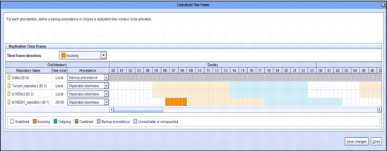
Figure 21-7 Centralized Replication Schedule Management
21.8.4 Replication rate control
There are enhanced system replication throttling and dynamic system resource allocation functions for incoming and outgoing replication. ProtecTIER replication offers the following enhanced features and benefits:
•Setting replication performance limits: It can be either a nominal or a physical limit. The nominal performance limit reflects the overall resource consumption of the system. The physical performance limit reflects the network transfer rate of the replication network.
•Enhancements to the replication rate control mechanism: Currently, the Replication Rate Control (RRC) is used when a user does not provide a time frame and the system replicates continuously. The rate calculation determines the maximum rate that is possible in both levels of system usage (IDLE and BUSY), and normalizes the rate.
•A GUI feature that provides an at-a-glance view of the proportion of the repository data, replication data, local backup data, and free space, as shown in Figure 21-8.

Figure 21-8 Repository usage by category
The nominal and physical throughput (data flow rate) can be limited by setting the RRC. The following information must be considered:
•Both the nominal and physical amounts of data that are being processed or transferred.
•The ability to send and receive new unique data between spokes and the hub.
•ProtecTIER validates all the new or updated objects at the target repository before it makes them available for the user. Setting the replication rate control enables the user to limit the nominal and physical throughput (data flow rate of replication). This feature can be used on spokes and on the hub for both sending and receiving. The values that are set in the physical throughput might, but do not necessarily, affect those values that are set in the nominal throughput, and vice versa. However, when you use both methods, the physical settings override the nominal ones.
Setting a nominal limit
When you set a nominal limit, you define the maximum ProtecTIER server system resources that can be used to process the replication data. The nominal throughput directly affects the replication data flow and the load on both the source and destination repositories.
On a ProtecTIER system that performs both backup and replication, setting a nominal replication limit enables you to select a replication throughput limit such that it does not compete with the backup operation for system resources. Setting the limit on a source repository ensures that the backup operation realizes the total possible throughput minus the nominal limit set.
For example, on a node with a performance capacity of 500 MBps that performs backup and replication concurrently, you might set the following limits:
•300 MBps when replication is running on its own
•100 MBps when replication is running concurrently with a backup
Setting a physical limit
When you set a physical limit, you limit replication network bandwidth consumption by the ProtecTIER server. This limit is intended to be used when the network is shared between the ProtecTIER server and other applications so that all applications can run concurrently. The physical throughput limit restrains the amount of resources that the replication processes can use. This limit reduces the total load on the replication networks that are used by the repository.
Although this limit can be set at either the spoke, the hub, or both, it is typically set at the spoke. Setting a limit at the hub results in de facto limitations on all spokes.
21.8.5 Setting replication rate limits
You can limit the replication rates and throughput (Figure 21-9) in the following situations:
•During a backup or restore operation
•When there is no backup or restore activity
•In a defined replication time frame

Figure 21-9 Setting replication rate limits
21.8.6 Limiting port bandwidth consumption
Bandwidth throttling (physical limit) controls the speed at which replication operates, where the user can specify a maximum limit for the network usage. By default, there is no configured bandwidth limit; the ProtecTIER server uses as much bandwidth as it can.
If the physical network layer consists of dark fiber or other high-speed network infrastructure, there is typically no reason to limit replication throughput. However, if the ProtecTIER server is running over a smaller network pipe that is shared by other applications, you can restrict the maximum physical throughput that is used by ProtecTIER replication.
This parameter is adjustable per Ethernet replication port on all nodes in the replication grid. It applies only to outgoing data. Set it at the source (sending) system. If the source system is composed of a dual-node cluster, be sure to consider all ports of both nodes when setting the limit.
For example, to hold ProtecTIER replication to a limit of 100 MBps, set each of the four available Ethernet replication ports to 25 MBps, as shown on Figure 21-10. Likewise, if the replication traffic is split between two networks with different bandwidth capacities, you can set different limits per port to implement a network-specific capacity. By default, the setting per port is Unlimited.
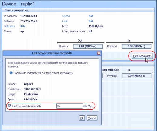
Figure 21-10 Potential modification of the replication interface limit
|
Changing the bandwidth: If the bandwidth limitation is changed during replication, the change does not take effect immediately. If replication begins after the bandwidth limitation change, the effect is immediate.
|
21.9 Replication backlog
When replication activity is started, the source system builds a list of new and changed data blocks and sends that list to the receiving system. The receiving system checks the list and determines which data blocks it must synchronize with the source system and then sends requests for the transferal of data blocks. Now, there is a backlog of data to replicate. The source system monitors and displays the amount of backlog replication data in the ProtecTIER Manager GUI Activities view.
Having a backlog of data to replicate is not inherently a problem. A potential problem is indicated when the amount of backlog replication data does not go down over time.
If there is an unscheduled long network or DR site outage, the replication backlog might become too large for the system to catch up. A prolonged replication backlog might be an indication of insufficient available bandwidth that is allocated for the replication operation. In an optimal situation, the replication backlog should follow the backup activities (Figure 21-11).

Figure 21-11 Backlog status in replication activities
Use either of these methods to dismiss the replication backlog:
•From the ProtecTIER Manager replication Policy view, select a specific policy and click Stop activity.
•From the ProtecTIER Manager replication Activities view, select a specific activity and click Stop activity.
These options cause the replication backlog to be discarded; if the replication activities are restarted, the replication backlog will be calculated at that time.
Stopping replication tasks
|
SLAs: For the system to support the organization’s set of SLAs, enough bandwidth must be allotted for replication during the replication window so that all the policies are run in the allotted time.
|
Stopping replication tasks removes them from the list of pending and running tasks. These tasks are automatically returned to the replication queue if the specific cartridge is in one of the following states:
•Appended
•Ejected from the library
•Selected for manual execution
One way to prevent these replication tasks from rerunning is to mark those cartridges as read-only either on the ProtecTIER server or by the backup application. These cartridges are not used for further backups, and therefore do not replicate. New (scratch) sets of cartridges are used for subsequent backups, and do not contain backlog data that does not need to
be replicated.
be replicated.
|
Tip: When backup activity is resumed, using a different set of bar codes can enable having the new data replicated, and skip replication of the data from the old cartridges.
|
21.9.1 SNMP alerts for replication backlog
ProtecTIER provides a Simple Network Management Protocol (SNMP) method for monitoring backlog data and notifying you if backlog data becomes greater than a user-defined threshold setting, as shown in Figure 21-12.

Figure 21-12 Replication backlog SNMP Alerts Reserving space for local backup data
ProtecTIER can reserve local-backup-only space for the hub repository. You can use this enhancement to exclusively assign a portion of a hub repository for local backups. This enhancement was added to ensure that capacity is reserved only for local backup. Replication cannot be written to this portion of the hub repository.
Error notifications display if the repository hub areas that are reserved for local backup or replication are reaching maximum capacity. Figure 21-13 shows the window for this enhancement.

Figure 21-13 Current capacity
21.10 Replication planning
The planning process for ProtecTIER systems with replication deployed requires more input and considerations beyond the individual capacity and performance planning that is needed for a system that is used only as a local VTL, or FSI. When a multiple-site, many-to-one, or many-to-many replication strategy is deployed, the entire configuration, including all spokes and hubs, must be evaluated.
The planning of a many-to-one replication environment is similar to the planning of a one-to-one replication strategy. The only difference is that you must combine all replication loads (and potentially a local backup) for the hub. The ProtecTIER Planner tool should be used at the planning stages before any ProtecTIER deployment Bandwidth sizing and requirements. For more details, see 7.1.1, “ProtecTIER Planner tool” on page 102.
The ProtecTIER server replicates only the new or unique deduplicated data. Data that was deduplicated on the primary server is not sent to the DR site. However, the DR site (hub) must synchronize with all of the data on the primary server to ensure 100% data integrity.
For example, two cartridges are at the primary site, cartridge A and cartridge B, and each contains the same 1 GB of data:
•Replicating Cartridge A transfers 1 GB of physical (which equals nominal) data. The data is new to the DR site repository.
•Replicating Cartridge B transfers 0 GB of physical data to the DR site. Because the same data was transferred with the Cartridge A replication, all of the Cartridge B data exists at the DR site repository. Following the replication action, 1 GB of nominal data is indexed on Cartridge B at the DR site.
|
Throughput: The maximum replication throughput for any scenario depends on many factors, such as the data type and change rate.
Tip: When you configure a system with unbalanced replication network lines, the total throughput is reduced to the slowest line.
The preferred practice is for both networks in the replication network topology to be set at the same speed at the source. If need be, set the speed of the port, by using ethtool, of the faster network to the same speed as the slower network. This is an example of
the command: ethtool -s eth2 speed 100
|
21.10.1 Replication throughput barriers
The following types of replication data transfer throughput barriers have been identified: physical data-transfer barrier and nominal data barrier.
Physical data-transfer barrier
This barrier results from the Ethernet ports used for replication on the ProtecTIER (1 Gbps or 10 Gbps).
•1 Gbps = 1000 Mbps = 125 MBps. If two 1 Gbps ports are used for replication, the maximum possible physical transfer rate is 250 MBps (125 MBps x 2).
•10 Gbps = 10,000 Mbps = 1250 MBps. If two 10 Gbps ports are used for replication, the maximum possible physical transfer rate is 2500 MBps (1250 MBps x 2).
The speed of the Ethernet ports is a reference of a physical speed limit that cannot be overpassed. Nevertheless, these physical speed limits are not usually reached, due to many factors that can reduce the transfer rates:
•TCP’s handshake phase. The three-way handshake imposes a certain latency penalty on every new TCP connection.
•Latency. Depending upon many factors along the network span, the latency in any WAN varies, but must never exceed 200 ms. If so, it might decrease the system replication throughput. For more information about this topic, contact your network administrator.
•Packet loss. Packet loss across the network should be 0%. Any other value indicates a major network problem that must be addressed before replication is deployed. For more information about this topic, contact your network administrator.
Nominal data barrier
The nominal data barrier results from the maximum processing capability of a given ProtecTIER system (3958-DD6):
•A single node system might support up to 1,660 MBps of nominal data backup ingest, replication, or a combination of these activities.
•A dual-node clustered system might support sustainable rates of up to 2,990 MBps of nominal data backup ingest, replication, or a combination of these activities.
|
Note: Maximum specifications are based on a TS7650G 3958-DD6 and a correctly configured back-end disk array. Typical restores are approximately 15 - 20% faster than backups.
|
21.10.2 Calculating the replication data transfer
Use the following formula to calculate the replication data transfer. The formula estimates the number of gigabytes of changed data to be sent across the network, and adds 0.5% for control data.
Replication data transfer = daily backup × (Change rate + 0.5%)
Example 21-1 shows this formula with values.
Example 21-1 Replication of a 6 TB daily backup with change rate of 10%
replication data transfer = 6,144 GB × (10% + 0.5%)= 645.12 GB
In this scenario, 645.12 GB of physical data is replicated to the secondary site, rather than 6 TB of nominal data that would otherwise be transferred without deduplication.
21.10.3 Calculating replication bandwidth
Use this formula to calculate the required replication bandwidth:
Replication bandwidth = replication data transfer ÷ available replication hours
Example 21-2 shows this formula with values.
Example 21-2 For a replication window of 10 hours
replication bandwidth = 645.12 GB ÷ 10h = 64.51 GB per hour
The WAN bandwidth must be able to transfer an average 64.51 GB per hour, which represents the requirements for an 18.34 MBps link between spoke and hub.
|
Tip: Continuous replication operation (24 hour replication concurrent with a backup operation) is rarely the suggested mode of operation. Add 10% of the required bandwidth for a buffer in case of network outages or slowdown periods.
|
21.10.4 Ports for replication in firewalled environments
In a firewalled environment, you must open the following TCP ports so that IP replication can function properly:
•The replication manager uses TCP ports 6202, 3501, and 3503.
•The replication operation between any two repositories uses TCP ports 6520, 6530, 6540, 6550, 3501, and 3503.
ProtecTIER replication does not use any User Datagram Protocol (UDP) ports.
21.11 Bandwidth validation utility
The pt_net_perf_util network testing utility is included as part of the ProtecTIER software package. As a part of the installation process, the installer must ensure that the ProtecTIER nodes at both sites (sender and receiver) can run this utility concurrently.
The objective of the pt_net_perf_util utility is to test maximal replication performance between two ProtecTIER repositories. It does so by emulating the network usage patterns of the ProtecTIER native replication component. This utility does not predict replication performance, but it might discover performance bottlenecks.
|
Tip: It is not necessary to build a repository or configure the ProtecTIER back-end disk to run the pt_net_perf_util test tool.
|
The utility includes the following requirements:
•Red Hat Enterprise Linux Version 5.2 or later.
•Standard external utilities that are expected to be in the current path are as follows:
– ping
– netstat
– getopt
– echo
The pt_net_perf_util utility uses the iperf tool internally. Both tools are installed as part of the ProtecTIER software installation; pt_net_perf_util is installed under path /opt/dtc/app/sbin, and iperf is installed under path /usr/local/bin.
|
Important: Prior to ProtecTIER Version 3.2, the pt_net_perf_util utility had the option to use internally either the iperf or nuttcp tools, but the option to use nuttcp was removed.
|
The utility has two modes of operation: client and server. The client is the ProtecTIER system that transmits the test data. The server is the ProtecTIER system that receives the replication data (also known as the target server). Based on the data that is sent by the client and received by the server, the script outputs key network parameter values that indicate certain attributes of the network.
The goal of these tests is to benchmark the throughput of the network. The most important benchmark is the direction that replication actually takes place. The replication target must be tested as the server, because the flow of data is to that server from the client. However, it is also important to test the reverse direction to measure the bandwidth performance during disaster recovery failback. Network bandwidth is not always the same in both directions.
21.11.1 Using the bandwidth validation utility to test the data flow
Consider the following generalities before you start the bandwidth validation process:
•Before you run the utility, the ProtecTIER services on both client and server need to be stopped.
•The server must be started and running before the client.
•Each test runs for 5 minutes (300 seconds). Because there are five tests, the process takes about 25 minutes.
Use these steps to test network performance between two ProtecTIER systems on a WAN:
1. Stop the services on both ProtecTIER systems that participate in the test.
Unless otherwise indicated, use the ProtecTIER Service menu to stop ProtecTIER services:
Manage ProtecTIER services > Stop ProtecTIER services only (including GFS)
2. Start the server mode of the pt_net_perf_util utility on the target server (the ProtecTIER system that receives the replication data).
Example 21-3 shows how to start the pt_net_perf_util utility in server mode. The -s flag indicates to the utility to start as server.
Example 21-3 Start pt_net_perf_util server mode
[root@tintan ~]# /opt/dtc/app/sbin/pt_net_perf_util -s
------------------------------------------------------------
Server listening on TCP port 5001
TCP window size: 85.3 KByte (default)
------------------------------------------------------------
3. Start the client mode of the pt_net_perf_util utility on the client (the ProtecTIER system that sends the replication data).
Example 21-4 shows how to start the pt_net_perf_util utility in client mode.
The -c <server> flag indicates to the utility to start as a client, and to connect to the given server. The -t flag indicates the seconds to run each test. Without the -t flag, the utility will not run, and an error (ERROR: -t not specified) along with the utility usage will be displayed. Unless otherwise indicated, use 300 seconds to start the client.
The -c <server> flag indicates to the utility to start as a client, and to connect to the given server. The -t flag indicates the seconds to run each test. Without the -t flag, the utility will not run, and an error (ERROR: -t not specified) along with the utility usage will be displayed. Unless otherwise indicated, use 300 seconds to start the client.
Example 21-4 Start pt_net_perf_util client mode
[root@torito ~]# /opt/dtc/app/sbin/pt_net_perf_util -c 10.0.5.44 -t 300
*** Latency
4. The utility automatically performs the tests in sequence; wait until the client completes all tests. Example 21-5 shows the output of the client after all tests completed running.
Example 21-5 Output of the pt_net_perf_util client
[root@torito ~]# /opt/dtc/app/sbin/pt_net_perf_util -c 10.0.5.44 -t 300
*** Latency
PING 10.0.5.44 (10.0.5.44) 56(84) bytes of data.
--- 10.0.5.44 ping statistics ---
300 packets transmitted, 300 received, 0% packet loss, time 298999ms
rtt min/avg/max/mdev = 0.066/0.118/0.633/0.039 ms
*** Throughput - Default TCP
[ 3] 0.0-300.0 sec 32.9 GBytes 942 Mbits/sec
*** Throughput - 1 TCP stream(s), 1024KB send buffer
[ 3] 0.0-300.0 sec 32.9 GBytes 942 Mbits/sec
*** Throughput - 16 TCP stream(s), 1024KB send buffer
[SUM] 0.0-300.4 sec 32.9 GBytes 942 Mbits/sec
*** Throughput - 127 TCP stream(s), 1024KB send buffer
[SUM] 0.0-303.7 sec 33.2 GBytes 940 Mbits/sec
Number of TCP segments sent: 4188852
Number of TCP retransmissions detected: 969530 (23.145%)
As the tests are run, the server prints output of each test. Example 21-6 shows excerpts of the output on the server.
Example 21-6 Output on the pt_net_perf_util server
[root@tinTAN ~]# /opt/dtc/app/sbin/pt_net_perf_util -s
------------------------------------------------------------
Server listening on TCP port 5001
TCP window size: 85.3 KByte (default)
------------------------------------------------------------
[ 4] local 10.0.5.44 port 5001 connected with 10.0.5.41 port 43216
[ ID] Interval Transfer Bandwidth
[ 4] 0.0-300.0 sec 32.9 GBytes 941 Mbits/sec
[ 5] local 10.0.5.44 port 5001 connected with 10.0.5.41 port 43227
[ ID] Interval Transfer Bandwidth
[ 5] 0.0-300.0 sec 32.9 GBytes 941 Mbits/sec
[ 4] local 10.0.5.44 port 5001 connected with 10.0.5.41 port 43238
[ 5] local 10.0.5.44 port 5001 connected with 10.0.5.41 port 43239
...
[ ID] Interval Transfer Bandwidth
[ 16] 0.0-300.4 sec 2.06 GBytes 58.8 Mbits/sec
[ ID] Interval Transfer Bandwidth
[ 18] 0.0-300.4 sec 2.05 GBytes 58.7 Mbits/sec
...
[ 20] local 10.0.5.44 port 5001 connected with 10.0.5.41 port 43264
[ 4] local 10.0.5.44 port 5001 connected with 10.0.5.41 port 43265
...
[ ID] Interval Transfer Bandwidth
[101] 0.0-303.9 sec 269 MBytes 7.43 Mbits/sec
[ ID] Interval Transfer Bandwidth
[ 88] 0.0-303.9 sec 224 MBytes 6.18 Mbits/sec
...
[ ID] Interval Transfer Bandwidth
[ 13] 0.0-306.9 sec 186 MBytes 5.08 Mbits/sec
[SUM] 0.0-306.9 sec 33.2 GBytes 930 Mbits/sec
5. Restart the ProtecTIER services after finishing the tests. Unless otherwise indicated, use the ProtecTIER Service menu to stop ProtecTIER services:
Manage ProtecTIER services > Start all services
21.11.2 Interpreting the results
The utility performs five foreground tests and one background test (TCP) re-transmissions (versus total TCP segments sent on the five foreground tests).
Interpretations of the following tests is based on the example output that is shown in Example 21-5 on page 383. Results vary in each environment.
Test 1: Latency
This test checks the nominal network link latency and packet loss. The following results can be interpreted:
•There was 0% packet loss.
•The average round-trip-time (RTT) was 0.118 ms.
The latency in WAN topologies might vary, but must never exceed 200 ms. Contact your network administrator if latency reports more than 200 ms. Higher latency values cause a major deterioration in replication throughput. Packet loss must be 0%, because any other value implies a major network problem.
Test 2: Throughput - Default TCP
This test checks the maximum TCP throughput by using a single data stream with default TCP settings. The following results can be interpreted:
•The test ran for 300 seconds.
•32.9 GB of data was transferred.
•The average throughput was 942 Mbps.
|
Remember: 1 MB = 1,048,576 bytes. 1 MBps = 1,000,000 Bps
|
Test 3: Throughput - 1 TCP stream(s), 1024 KB send buffer
This test checks the maximum TCP throughput by using a single data stream with a 1 MB send buffer. The following results can be interpreted:
•The test ran for 300 seconds.
•32.9 GB of data was transferred.
•The average throughput was 942 Mbps.
Test 4: Throughput - 16 TCP stream(s), 1024 KB send buffer
This test checks the maximum TCP throughput by using 16 data stream with a 1 MB send buffer. The following results can be interpreted:
•The test ran for 300.4 seconds.
•32.9 GB of data was transferred.
•The average throughput was 942 Mbps.
The megabits per second reported in this test is the maximum replication performance the system can achieve if the backup environment uses three or fewer cartridges in parallel.
Test 5: Throughput - 127 TCP stream(s), 1024 KB send buffer
This test checks the maximum TCP throughput by using 127 data streams with a 1 MB send buffer. The following results can be interpreted:
•The test ran for 303.7 seconds.
•33.2 GB of data was transferred.
•The average throughput was 940 Mbps.
The throughput value that is given by this test is the potential physical replication throughput for this system. It is directly affected by the available bandwidth, latency, packet loss, and retransmission rate. If this number is lower than anticipated, contact your network administrator.
Test 6: TCP retransmissions versus total TCP segments sent
This test compares the total TCP transmissions sent with the number of packets that are lost and retransmitted. The following results can be interpreted:
•A total of 4,188,852 TCP segments were sent during the five tests.
•969,530 were lost and retransmitted.
•The retransmission rate is 23.145%.
The retransmission rate imposes a direct penalty on the throughput, because the retransmission of these packets take up bandwidth. The retransmission can be caused by the underlying network (for example, packet dropping by an overflowed router). It can also be caused by the TCP layer (for example, retransmission because of packet reordering). Segment loss can be caused by each of the network layers.
|
Important: TCP retransmission larger than 2% might cause performance degradation and unstable network connectivity. Contact your network administrator to resolve this issue.
|
21.11.3 Repository replacement
Use the repository replacement function when you want to fail back to a different repository or rebuild a repository. To accomplish this task, complete the following steps:
1. Cancel the pairing of the original repositories in the replication manager.
2. Take the original primary repository out of the replication grid.
|
Important: If a new repository replaces the original one, then the new repository must be installed and join the replication grid.
|
3. Run the ProtecTIER repository replacement wizard and specify the repository to be replaced and the replacement repository.
After the disaster recovery situation ends and the primary repository is restored or replaced, you can return to normal operation with the replacement repository on the production site as the primary site.
Figure 21-14 shows how to leave ProtecTIER DR mode by selecting Replication → Replication Disaster Recovery → Leave DR mode.

Figure 21-14 Leaving ProtecTIER DR mode
|
Important: Leaving DR mode should always be preceded by a failback action.
|
For more information, see IBM TS7650 with ProtecTIER V3.4 User's Guide for VTL Systems, GA32-0922-10.
Cartridge ownership takeover
Cartridge ownership takeover enables the local repository, or hub, to take control of cartridges that belong to a deleted repository. Taking ownership of the cartridges on a deleted repository enables the user to write on the cartridges that previously belonged to the replaced (deleted) repository. This process is also known as a change of principality.
|
Cartridge ownership: The repository can take ownership of a cartridge only if the repository is defined on the Replication Manager as the replacement of the deleted repository.
|
21.12 Planning ProtecTIER replication
This section provides case studies of planning and sizing ProtecTIER Replication. Both many-to-one (spoke and hub) replication environment and many-to-many bidirectional replication scenarios are described.
21.12.1 Deployment planning scenario: many-to-many
This section shows a deployment planning scenario for four sites, each with a dual-node gateway, building a maximum of four repositories, many-to-many VTL configuration, with various replication strategies.
VTL and FSI systems are configured in many-to-many replication groups, so this same sizing strategy applies, but the throughput numbers vary for each type.
At the time of the writing of this book, the maximum listed speed for a dual-node DD6 VTL gateway is 2500 MBps, so all calculations are based on this speed. As ProtecTIER technology improves, the rated performance numbers continue to increase. For the current published ratings, see the following web page:
Assume that the following characteristics of the replication grid are present:
•All processes have the same maximum rate (2,500 MBps).
•All data exists at all sites.
Maximum backup with no replication
With no data replication, a maximum of 24 hours can be used to accept backup data. One 24-hour time slot translates to 216 TB per day for each system. This is not a recommended configuration; it is included in this scenario for purposes of the example.
Figure 21-15 shows an overview of this scenario.

Figure 21-15 Maximum workload with no replication
Maximum workload with one replicated copy
For this example, all four ProtecTIER systems receive and replicate the same maximum amount of data that is possible in a 24 hour period. Because the workloads are equal, you can divide the 24 hour period into three equal time slots:
•One backup process (all four nodes accept backup at the same time.)
•One incoming replication processes
•One outgoing replication processes
With one data replication for each node, a maximum of 8 hours can be used to accept backup data. One 8 hour time slot translates to 72 TB per day for each system.
Figure 21-16 shows an overview of this scenario.

Figure 21-16 Maximum workload with one replicated copy
Two replicated copies
For this example, all four ProtecTIER systems receive and replicate the same maximum amount of data that is possible in a 24 hour period. Because the workloads are equal, you can divide the 24 hour period into five equal time slots:
•One backup process (all four nodes accept backup at the same time.)
•Two incoming replication processes
•Two outgoing replication processes
With two data replications for each node, a maximum of 4.8 hours can be used to accept backup data. One 4.8 hour time slot translates to 43 TB per day for each system.
Figure 21-18 on page 390 shows an overview of this scenario.

Figure 21-17 Maximum workload with two replicated copies
Three replicated copies
For this example, all four ProtecTIER systems receive and replicate the same maximum amount of data that is possible in a 24 hour period. Because the workloads are equal, you can divide the 24 hour period into seven equal time slots:
•One backup process (all four nodes accept backup at the same time)
•Three incoming replication processes
•Three outgoing replication processes
With three data replications for each node, a maximum of 3.4 hours can be used to accept backup data. One 3.4 hour time slot translates to 30.6 TB per day for each system.
Figure 21-18 shows an overview of this scenario.

Figure 21-18 Maximum workload with three replicated copies
Table 21-1 depicts activity in different time frames in a 4-way many-to-many replication configuration.
Table 21-1 Example of a 4-way many-to-many replication configuration
|
Time frame
|
Activity
|
|
1
|
All systems process backups at 2500 MBps for 3.4 hours (30.6 TB).
|
|
2
|
System C replicates to B at 2500 MBps for 3.4 hours.
System D replicates to A at 2500 MBps for 3.4 hours.
|
|
3
|
System C replicates to D at 2500 MBps for 3.4 hours.
System A replicates to B at 2500 MBps for 3.4 hours.
|
|
4
|
System C replicates to A at 2500 MBps for 3.4 hours.
System B replicates to D at 2500 MBps for 3.4 hours.
|
|
5
|
System B replicates to A at 2500 MBps for 3.4 hours.
System D replicates to C at 2500 MBps for 3.4 hours.
|
|
6
|
System D replicates to B at 2500 MBps for 3.4 hours.
System A replicates to C at 2500 MBps for 3.4 hours.
|
|
7
|
System B replicates to C at 2500 MBps for 3.4 hours.
System A replicates to D at 2500 MBps for 3.4 hours.
|
21.12.2 Many-to-one replication
The specific performance numbers would vary depending of the ProtecTIER model used, but this same process can be followed for IBM System Storage TS7620 small and medium business (SMB) appliances and TS7650G Gateway systems when sizing and planning a replication scenario. Figure 21-19 shows a many-to-one replication example.

Figure 21-19 Many-to-one replication example
Assumptions
The case modeling is based on the following assumptions:
•A maximum environment of 12 Spoke systems and one hub system.
•Eight hour backup windows (hub and spokes).
•A 16 hour replication window.
•All windows are aligned, meaning that the eight hour backup window is the same actual time at all 13 ProtecTIER systems (spokes and hub).
•Adequate bandwidth between all spokes and hub.
•A 10:1 deduplication ratio throughout the system.
•Data change rate at spokes does not saturate physical reception capabilities at the hub.
Maximum workloads assumed
The values for the maximum workloads are as follows:
•Hub backup:
– 8-hour backup window.
– 9 TB per hour (2500 MBps).
– 72 TB of nominal daily backup at the hub.
– 16-hour replication window.
– 9 TB per hour (2500 MBps) replication performance.
– 144 TB of nominal data can be replicated from all spokes.
•Spoke backup:
– 8-hour backup window.
– 144 TB for all 12 spokes = 12 TB of daily backup data per spoke.
– 12 TB/eight hours = 1.5 GB per hour or 1500 MBps sustained for eight hours.
– A spoke can potentially back up 72 TB of nominal data, but can replicate only 12 TB because of configuration constraints.
Sizing the repositories for spokes and hub
This section provides examples for sizing repositories for spokes and hubs. It also provides examples for calculating local backup space and incoming replication space.
Example of spoke repository sizing
In this example, each spoke can process up to 12 TB per day of local backup data, with a 10:1 deduplication ratio.
To size the spoke repository in this example, complete the following steps:
1. Assuming a 10:1 deduplication ratio, approximately 1200 GB of new data must be replicated to the hub per backup. The total daily space for 27 incremental backups is calculated as follows:
1,200 GB x 27 incrementals = 32,400 GB (or ~32 TB) of physical space (for incrementals)
2. With a backup compression ratio of 2:1, add 6 TB for the first “full” backup (12 TB at 2:1 compression):
32 TB + 6 TB = 38 TB of physical space for incrementals and full backup
3. Calculate the space that is necessary for spare capacity by multiplying the total physical space that is needed by 10%:
38 TB x 10% = 3.2 TB of spare capacity
4. Calculate the total physical repository for each spoke by adding the total physical space that is needed and the spare capacity:
38 TB + 4 TB = 42 TB
Example of hub repository sizing
The hub repository must be sized to handle 27 days of local backups and 27 days of incoming replication from all 12 spokes plus approximately 10% spare capacity.
Local backup space
In this example, the hub system can back up 72 TB in the 8-hour window. The first full backup at the hub requires 36 TB of physical space (72 TB @ 2:1 compression ration). With a 10:1 deduplication ratio, the hub accumulates 7.2 TB of new data for each of the next 27 days.
The following example is the calculation for the local backup space:
36 TB +194.4 TB (7.2 TB x 27 days) = 230.4 TB
Incoming replication space
To calculate the incoming replication space in this example, complete the following steps:
1. Calculate the hub repository space for a full backup of all 12 spokes at 2:1 compression:
(12 TB x 12 spokes)/2 = 72 TB of repository space
2. Assuming a 10:1 deduplication ratio, approximately, 1,200 GB (1.2 TB) of new data per spoke must be replicated to the hub per backup. Calculate the new data received daily at the hub from all spokes:
1200 GB x 12 spokes = 14.4TB of new data
3. The total daily space for 27 incremental backups is calculated as follows:
14.4 TB x 27 incrementals = 388 TB of physical space
4. The total hub repository space that is necessary to accommodate the 27 incremental backups and one full backup is:
230.4 TB + 388 TB +40 TB (10% spare capacity) = 464 TB for hub repository space
21.13 The backup application database backup
Figure 21-20 illustrates a typical backup and DR environment using the ProtecTIER product.

Figure 21-20 Typical backup and DR environment using the ProtecTIER product
The backup application environment is straightforward. The backup application servers are connected to storage devices (disk, real tape, or virtual tape). Every action and backup set that the backup servers process is recorded in the backup application database or catalog. The catalog is at the heart of any recovery operation. Without a valid copy of the database or catalog, restoration of data is difficult, and sometimes even impossible.
The ProtecTIER server provides a virtual tape interface to the backup application server, which you can use to create tapes, as represented by ONSITE_VTAPE_POOL in Figure 21-20 on page 393. The client can also maintain another tape library to create real tapes to take off-site, called OFFSITE_TAPE in Figure 21-20 on page 393.
ONSITE_VTAPE_POOL is where most client recoveries and restores come from. The key advantage of this architecture is that restoration occurs much faster because the data is coming from the ProtecTIER disk-based virtual tape rather than from real tape.
..................Content has been hidden....................
You can't read the all page of ebook, please click here login for view all page.