

Configuring settings
This chapter describes the Settings function (Figure 7-1 on page 232) of the IBM FlashSystem 900 graphical user interface (GUI). The Settings function offers various options for monitoring, configuring network interfaces, and extracting support logs. It also offers remote authentication and the firmware update process, and explains how to access IBM FlashSystem 900 Service Assistant Tool.
This chapter covers the following topics:
7.1 Settings menu
You can use the Settings function to configure system options for event notifications, security, IP addresses, FC connectivity, and preferences related to display options in the management GUI.
The Settings menu includes these options:
•Notifications: Alerting
•Network: Management and service
•Security: Remote authentication with Lightweight Directory Access Protocol (LDAP)
•System: Time settings, firmware update, and so on
•Support: Extract support logs
•GUI Preferences
7.1.1 Navigating to the Settings menu
If you hover the cursor over the Settings function icon, the Settings menu opens (Figure 7-1).

Figure 7-1 Navigate to the Settings menu
7.1.2 Notifications menu
FlashSystem 900 can use Simple Network Management Protocol (SNMP) traps, syslog messages, and call home email to notify you and IBM Support when significant events are detected. Any combination of these notification methods can be used simultaneously.
Notifications are normally sent immediately after an event is raised. However there are exceptions. For example, event 085031 “Array is missing a spare flash module”, (SEC 1690) does not report until the rebuild is complete. Also, certain events might occur because of service actions that are performed. If a recommended service action is active, these events are sent only if they are still not fixed when the service action completes.
Email
The call home feature transmits operational and event-related data to you and IBM through a Simple Mail Transfer Protocol (SMTP) server connection in the form of an event notification email. When configured, this function alerts IBM service personnel about hardware failures and potentially serious configuration or environmental issues.
To configure email alerts, navigate to Settings → Notifications. The Notifications window opens (Figure 7-2). From this window, you can configure the email alerts that are included in the call home function. During the configuration of call home, you configure contact information and email receivers for your own notification.

Figure 7-2 Event Notifications Email window
To initiate the configuration wizard, click Enable Notifications; the setup call home window opens. The procedure for configuring call home is similar to the initialization of the IBM FlashSystem 900, which also offers configuration of Email Event Notifications. The initial System setup is described in “System Setup wizard” on page 88.
The steps to enable call home involve configuring these items:
•System Location: Where is the system located?
•Contact Details: Who should IBM contact in case of a call-home situation?
•Email Servers: What is the IP address of the SMTP email server?
•Email Notifications: Who else requires notification through email?
Figure 7-3 shows the Welcome window in the Email Events Notification wizard. Click Next to continue.

Figure 7-3 Notifications Welcome
Figure 7-4 shows how the System Location details are configured. This is the address and location of the system, and where IBM Support assumes the system is located when a call home is received. Click Next to continue.

Figure 7-4 Notifications System Location
|
Note: The State or province field and Country or region field must be configured correctly, otherwise IBM Support is not able to react on call home calls from the system.
You can test the validity of this field by submitting an Email Notification test. Wait until the Email Notification wizard finishes to submit your test. IBM Support will contact your organization if settings are configured correctly.
|
Figure 7-5 shows how the client contact is configured. To continue, click Apply and Next.

Figure 7-5 Notifications Contact Details
To send email, the IBM FlashSystem 900 needs to know which mail server can transport the email. It also needs to know the TCP port through which the emails are sent.
Figure 7-6 demonstrates how to configure an SMTP email server. Multiple SMTP email servers can be configured by clicking the plus sign (+) to the right of the Server Port box. Click Apply and Next to continue.

Figure 7-6 Notifications Email Servers
The call home feature from the IBM FlashSystem 900 is enabled by sending an email to IBM at a fixed email destination address that cannot be altered.
Optionally, you can configure event notifications to additional email receivers. Email notification to IBM Support is automatically configured, but typically the client prefers to be notified if any issues occur that need attention. Client event notification is valuable if email transport to IBM fails. An email transport error can occur in an SMTP server outage, or if the SMTP server IP address is changed without the call home function of the IBM FlashSystem 900 being updated correctly.
Additional mail receivers can be configured, as shown in Figure 7-7. Click Apply and Next to continue.

Figure 7-7 Notifications email receivers
A summary is displayed when all configurations are ready to be applied (Figure 7-8). Click Finish to apply the Email Notification settings.

Figure 7-8 Notifications summary
Event notifications are now active and the system is reporting to IBM in case of hardware failure. The Email panel of the Settings > Notifications window displays information (Figure 7-9).

Figure 7-9 Notifications are now enabled and active
Mail receivers can be tested by clicking Edit and then Test for each of the mail receivers. Testing the call home receiver generates a support call at IBM and you are contacted to confirm successful configuration of call home.
SNMP
Simple Network Management Protocol (SNMP) is a standard protocol for managing networks and exchanging messages. The system can send SNMP messages that notify personnel about an event. You can use an SNMP manager to view the SNMP messages that the system sends.
|
Note: You can download the FlashSystem 900 management information base (MIB) file from the FlashSystem 900 GUI at the Settings → System → Notifications → SNMP page.
|
Figure 7-10 shows the SNMP configuration menu.

Figure 7-10 Event notifications SNMP window
In the SNMP configuration menu, you can configure one or more SNMP servers. For each of these SNMP servers, you configure the following information:
•IP address
•SNMP server port: The default is port 162.
•SNMP community: The default is public.
•Event type: The default is Alerts but it can be changed to All events.
Various SNMP trap receiver products are on the market. These are known as SNMP managers. IBM Tivoli NetView® or IBM Tivoli Enterprise Console® can be used as IBM SNMP managers.
Syslog
The syslog protocol is a standard protocol for forwarding log messages from a sender to a receiver on an IP network. The IP network can be either IPv4 or IPv6. The system can send syslog messages that notify personnel about an event.
The IBM FlashSystem 900 can transmit syslog messages in either expanded or concise format. You can use a syslog manager to view the syslog messages that the system sends. The system uses the User Datagram Protocol (UDP) to transmit the syslog message. You can specify up to a maximum of six syslog servers (Figure 7-11).

Figure 7-11 Event notifications Syslog window
In the Syslog configuration menu, you can configure one or more syslog servers. For each of these servers, you configure the following information:
•IP address
•Facility
The facility determines the format for the syslog messages and can be used to determine the source of the message.
•Event type (The default is Alerts but it can be changed to All events.)
Various syslog server products are on the market. Many of these products are no-charge products that can be downloaded from the Internet.
7.1.3 Security menu
The security menu provides configuration of the following options:
•Remote authentication
When remote authentication is configured, users authenticate with their domain user and password rather than a locally created user ID and password. Remote authentication gives you central access control. If someone leaves the company, you only need to remove access at the domain controller, which means that no orphan user IDs remain on the storage system.
•Encryption
The IBM FlashSystem 900 provides encryption, which protects against the potential exposure of sensitive user data and user metadata that are stored on discarded, lost, or stolen flash modules. Protection of encrypted data is enforced by encryption keys stored on external USB flash drives. A USB flash drive with a valid encryption key must be placed in one of the USB connectors of the FlashSystem 900 during power up, reboot and many repair actions.
Configure remote authentication
When a FlashSystem 900 clustered system is created, the authentication settings default to local, which means that the IBM FlashSystem 900 contains a local database of users and their privileges. Local users can be created by the superuser account.
You can create two types of users who can access the system. These types are based on how the users authenticate to the system. Local users are authenticated through the authentication methods that are located on the IBM FlashSystem 900.
If the local user needs access to the management GUI, a password is needed for the user. If the user requires access to the command-line interface (CLI) through Secure Shell (SSH), either a password or a valid SSH key file is necessary. Local users must be part of a user group that is defined on the system. User groups define roles that authorize the users within that group to a specific set of privileges on the system.
For users of the FlashSystem 900 clustered system, you can configure authentication and authorization using the CLI and the GUI as configured in the Users and User Groups menu.
A remote user is authenticated on a remote service with Lightweight Directory Access Protocol (LDAP) as configured in the Settings → Security section of the FlashSystem 900 GUI (Figure 7-1 on page 232). Remote users have their roles defined by the remote authentication service.
Remote authentication is disabled by default and can be enabled to authenticate users against LDAP servers.
A user who needs access to the CLI must be configured as a local user on the IBM FlashSystem 900.
Remote users do not need to be configured locally; they need to be defined only on the LDAP server.
For more information about how to configure remote authentication and authorization for users of the IBM FlashSystem 900, search for the “User authentication configuration” section of the IBM FlashSystem 900 web page of the IBM Knowledge Center:
Reasons for using remote authentication
Use remote authentication for the following reasons:
•Remote authentication saves you from having to configure a local user on every IBM storage system that exists in your storage infrastructure.
•If you have multiple LDAP-enabled storage systems, remote authentication makes it more efficient to set up authentication.
•The audit log shows the domain user name of the issuer when commands are executed. The domain user name is more informative than a local user name or just superuser.
•Remote authentication gives you central access control. If someone leaves the company, you only need to remove access at the domain controller, which means that no orphan user IDs remain on the storage system.
Prepare the LDAP server
The first step in configuring LDAP is to prepare the LDAP server. This example use a Microsoft Windows 2008 R2 Enterprise server, which is promoted to be a Domain Controller by using the dcpromo command. Next, the computer role Active Directory Lightweight Directory Services is added.
The privileges that the LDAP user gets on the IBM FlashSystem 900 are controlled by user groups on the storage system. There must be matching user groups on the Active Directory (AD) server and on the IBM FlashSystem 900, and the LDAP users must be added to the AD server group.
In this example, you create a group called FlashAdmin, which you use to manage your FlashSystem 900 storage device.
1. To create this group, log on to the AD Domain Controller and configure Active Directory. An easy way to configure Active Directory from the AD controller is to select Start → Run, type dsa.msc, and click OK. The Active Directory Users and Computers management console opens (Figure 7-12).
Click the Create a new group in the current container icon.

Figure 7-12 Active Directory Users and Computers window to create a new group
2. In the New Object - Group window that opens (Figure 7-13 on page 245), type FlashAdmin for the new group name, keep the remaining default values, and click OK.

Figure 7-13 Active Directory to create a FlashAdmin group
3. Highlight the users that you want to add to the FlashSystem 900 storage administrator group and click the Adds the selected objects to a group you specify icon (Figure 7-14).

Figure 7-14 Adds the selected objects to a group you specify

Figure 7-15 Active Directory Select Groups window to add users to the FlashAdmin group
Any other users that might be added to the FlashAdmin group get the same privileges on your FlashSystem 900.
If other users with other privileges are required, another group on the IBM FlashSystem 900 with different privileges is required. A group on the AD server with a matching name is also required.
Your LDAP server is now prepared for remote authentication.
Enable remote authentication on FlashSystem 900
The next step in configuring remote authentication for the IBM FlashSystem 900 is to specify the authentication server, test connectivity, and test whether users can authenticate to the LDAP server. As shown in Figure 7-1 on page 232, the Settings > Security page has these two options:
•Remote authentication
•Encryptions
If you select, Remote Authentication, the Remote Authentication panel opens. You can configure user authentication.
The following items are highlighted in Figure 7-16:
1. The default authentication method is local authentication
2. The current authentication method is specified; authentication is enabled.
Click Configure Remote Authentication.

Figure 7-16 Enable remote authentication

Figure 7-17 Remote Authentication wizard (step 1 of 4)
In the Configure Remote Authentication window (Figure 7-18), select Microsoft Active Directory, for Security, select None, and click Advanced Settings to expand it.

Figure 7-18 Remote Authentication wizard (step 2 of 4)
Any user with authority to query the LDAP directory can be used to authenticate. The Active Directory domain is itsolab.ibm.com, so use the Administrator login name on the itsolab.ibm.com domain to authenticate (Figure 7-19). Then, click Next.

Figure 7-19 Remote Authentication wizard (step 3 of 4)
Type the IP address of the LDAP server, which in this case is 9.xx.xx.xxx, and the LDAP Group Base Domain Name (DN) for Microsoft Active Directory.
You can obtain the LDAP User and Group Base DN for Microsoft Active Directory by using the following commands:
dsquery user -name <username>
dsquery group -name <group name>
To look up the Base DN, log on to the LDAP server and run the commands shown in Example 7-1.
Example 7-1 Checking the LDAP server for the Base DN
C:UsersAdministrator>dsquery group -name FlashAdmin
"CN=FlashAdmin,CN=Users,DC=itsolab,DC=ibm,DC=com"
C:UsersAdministrator>
The Base DN to which you need to enable LDAP authentication requires only the domain part of the output in Example 7-1. In the Base DN (Optional) field of the Configure Remote Authentication window (Figure 7-20), enter the following text:
DC=itsolab,DC=ibm,DC=com

Figure 7-20 Remote Authentication wizard (step 4 of 4)
Click Finish to return to the Settings > Security window. Figure 7-21 shows that LDAP is enabled and the window shows the preferences of the configured LDAP server.

Figure 7-21 Remote Authentication enabled
Create the FlashSystem 900 LDAP-enabled user group
The first part of the LDAP configuration is complete. You need, however, to create a new user group on your FlashSystem 900 with a name that matches the name that you configured on the LDAP server. For this, configure the name FlashAdmin on the LDAP server.

Figure 7-22 Navigate to User Groups

Figure 7-23 Create a new user group
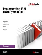
3. Select Security Administrator and select Enable for this group for the LDAP (Figure 7-24). Type the group name FlashAdmin for the new user group.
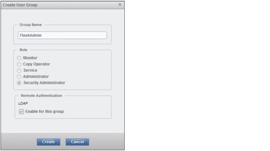
Figure 7-24 Select Security Administrator
|
Note: If the field Remote Authentication is not visible in the Create User Groups window, remote authentication is disabled in Settings → Security.
|
The new user group is created and enabled for remote authentication (Figure 7-25).

Figure 7-25 Group FlashAdmin created
Testing LDAP authentication
At this point, you can log out the user superuser and try to log in with the LDAP user. However, before you do that, the Remote Authentication window provides a capability to test LDAP.
1. From the FlashSystem 900 GUI, select Settings → Security → Remote Authentication → Configure Remote Authentication → LDAP.

Figure 7-26 Remote Authentication: Test LDAP Connections option
The Test LDAP Connections task window opens and displays the CLI command used to test the connection. In a successful connection to the LDAP server, the output is shown (Figure 7-27).

Figure 7-27 Remote Authentication: Test LDAP connections CLI result
From the Global Actions menu, you also can test whether the authentication for a specific user is functional. Click Test LDAP Authentication. The window shown in Figure 7-28 opens. Type the credentials of the LDAP user for whom you want to test authentication and click Test.

Figure 7-28 Remote Authentication: Test LDAP Authentication
The CLI command window opens. If the authentication is successful, you see the same output as shown in Figure 7-27 on page 251.
If the test is unsuccessful, you see the message shown in Figure 7-29.

Figure 7-29 Remote Authentication: Test unsuccessful
Log in as an LDAP user
Assuming that remote authentication is successful, the superuser user can now log out and the LDAP user can log in as shown in Figure 7-30.

Figure 7-30 Login window for the LDAP user
Figure 7-31 shows the FlashSystem 900 home window. The upper-right corner indicates which user is currently logged in.

Figure 7-31 Main window LDAP user logged in
Configuring remote authentication is complete.
About encryption
The IBM FlashSystem 900 provides optional encryption of data at rest, which protects against the potential exposure of sensitive user data and user metadata that are stored on discarded, lost, or stolen flash modules. Encryption of system data and system metadata is not required, so system data and metadata are not encrypted.
AES-XTS 256 bit data-at-rest encryption with local key management
Two functions are added to the encryption feature:
•Hot Encryption Activation: Adding an encryption license to a previously initialized system
•Encryption Rekey: Changing the encryption key on a previously initialized system
If you want to use encryption, ensure that you purchased feature code (FC) AF14: Encryption Enablement Pack (Plant).
Data Encryption Methology
The IBM FlashSystem 900 data encryption uses the Advanced Encryption Standard (AES) algorithm, with a 256-bit symmetric encryption key in XTS mode. This encryption mode is known as XTS–AES–256, which is described in the IEEE 1619–2007 data encryption standard. The data encryption key itself is protected by a 256-bit AES key wrap when it is stored in non-volatile form. Two layers of encryption are used with stored data:
•The data being protected
•The data encryption key itself
Protection Enablement Process
The Protection Enablement Process (PEP) transforms a system from a state that is not protection-enabled to a state that is protection-enabled.
The PEP establishes a secret encryption access key to access the system, which must be stored and made available for use at a later time, whenever the system needs to be unlocked. The secret encryption access key must be stored outside the system on a USB drive, which the system reads to obtain the key. The encryption access key should also be backed up to other forms of storage.
Encryption capability of FlashSystem 900 consists of two functions:
•Hot Encryption Activation
Allows an unencrypted FlashSystem to be encryption-enabled while the system is running, without impacting customer data in any way.
•Non-Disruptive Rekey
Permits creating a new encryption access key that supersedes the existing key on a running FlashSystem without impacting customer data.
Handling encryption and encryption keys has several aspects:
•Activating encryption using GUI
•Activating encryption using CLI
•Creating new encryption keys (Rekey)
•Keeping encryption keys from more systems on the same USB flash drives (stacking)
•Making copies of encryption keys
•Storing copies of USB flash drives holding encryption keys
•Leaving encryption keys in or out of the system during normal operation
About USB flash drives and encryption keys
The FlashSystem 900 predecessor FlashSystem 840 offered the possibility to initialize a new system and enable encryption during the initialization process using InitTool. With FlashSystem 900 and InitTool, enabling encryption during the initialization process is no longer an option. Encryption is enabled after initialization using either the GUI or CLI.
However the same rules for handling encryption keys on USB flash drives are the same.
When the encryption Feature Code AF14 is purchased, IBM sends a total of three USB flash drives: one USB flash drive for the system and two additional USB flash drives for the encryption feature code.
When encryption is activated, an encryption key is generated by the system to be used for access to encrypted data that is stored on the system. The GUI launches a wizard that guides you through the process of copying the encryption key to multiple USB flash drives. The following actions are considered preferred practices for copying and storing encryption keys:
1. Make copies of the encryption key on at least three USB flash drives to access the system.
2. In addition, copy the encryption keys to other forms of storage to provide resiliency and to mitigate risk, if, for example, the three USB flash drives are from a faulty batch of drives.
3. Test each copy of the encryption key before writing any user data to the initialized system.
4. Securely store all copies of the encryption key. As an example, any USB flash drives that do not remain inserted into the system can be locked in a safe. Use comparable precautions to securely protect any other copies of the encryption key stored to other forms of storage.
Enable the encryption license using GUI
To install the encryption license on a previously initialized system, complete these steps:

Figure 7-32 Encryption license not enabled
The encryption license is currently not enabled which shows a blank because Licensed is not selected. The Licensed column is not a modifiable column. To enable the encryption license, follow the next steps (shown in Figure 7-33, Figure 7-34 on page 256, and Figure 7-35 on page 256). After those steps are complete, a green check mark is indicated under the Licenses column.
2. Click Actions → Modify License. In the Modify Licenses window (Figure 7-33), select I have purchased an encryption license and click Modify.

Figure 7-33 Modify license
When you return to the Licensed Functions window, the encryption license is now installed and ready for use (Figure 7-34).

Figure 7-34 Encryption license is now enabled.
Enable encryption using GUI
Follow these steps to enable encryption using the GUI. For handling encryption using CLI, work with IBM Support for accurate handling procedures.
1. To enable encryption, click Settings → Security → Encryption and click Enable Encryption (Figure 7-35).

Figure 7-35 Enable encryption
The Enable Encryption wizard opens to the Welcome page (Figure 7-36). The next step requires two USB flash drives.

Figure 7-36 Enable Encryption wizard Welcome page
2. Insert two USB flash drives into the FlashSystem 900 controller USB ports and click Next. The encryption keys are now generated and stored on both USB keys, and detected (Figure 7-37).

Figure 7-37 Encryption keys writes to USB flash drives
If the system does not recognize USB keys, an error message is issued and the Enable Encryption process cannot continue until USB drives are inserted into the USB ports.
When the process finishes, a message indicates that encryption is enabled (Figure 7-38).

Figure 7-38 Encryption is now enabled
Figure 7-39 shows Settings → Security → Encryption after encryption is enabled. The system reports that USB flash drives are inserted into the USB ports of both nodes and that encryption keys are validated on these drives.

Figure 7-39 Encryption enabled and keys validated
Working with an encrypted FlashSystem 900
At system start-up (power on) or to access data on an encrypted system, the encryption key must be provided by an outside source so that the system. The encryption key is read from the USB flash drives that store copies of the keys that were created during system initialization. If you want the system to reboot automatically, a USB flash drive with the encryption keys must remain inserted in each canister, so that both canisters have access to the encryption key when they power on.
This method requires that the physical environment where the system is located is secure, so that no unauthorized person can make copies of encryption keys on the USB flash drives and gain access to data stored on the system. For the most secure operation, do not keep the USB flash drives inserted into the canisters on the system. However, this method requires that you manually insert the USB flash drives that contain copies of the encryption key in both canisters before rebooting the system.
The encryption key is required to access encrypted data, and it resides only on the USB flash drive copies and on any additional copies made on other forms of storage. The encryption key cannot be recovered or regenerated by IBM if all user-maintained copies are lost or unrecoverable.
|
Attention: Encryption keys or data from FlashSystem 900 cannot be recovered or regenerated by IBM on an encryption-enabled system if encryption keys are lost.
|
Handling encryption using CLI
In addition to using FlashSystem GUI to enable encryption and handle encryption keys, the FlashSystem CLI can be used to enable encryption while the FlashSystem 900 is running. This is a non-destructive procedure when handled correctly.
|
Note: Handling encryption using CLI involves numerous risks. To protect and preserve data, contact IBM Support for assistance with this procedure.
|
7.1.4 Network menu
The Network menu is used for the configuration of the network setup for all the interfaces in the cluster.
Click Settings → Network to open the Network menu. You can update the network configuration, configure Service IP addresses, and view information about the Fibre Channel (FC) connections.
Management IP addresses
The Management IP address is the IP address of the FlashSystem 900 management interface. This interface includes the GUI and the CLI. The GUI is accessed through a web browser and the CLI is accessed through SSH using PuTTY or a similar tool. The Management IP address is a clustered IP address, which means that if any of the canisters are offline for maintenance or for any other reason, the Management IP address is still available on the surviving node.
The configured Management IP address can be reviewed or changed by selecting Settings → Network → Management IP Address. The Management IP Address page opens (Figure 7-40).

Figure 7-40 Network menu: Set management IP address
Service IP addresses
The Service IP addresses are the IP addresses of each of the two FlashSystem 900 controllers, which are called canisters. These canisters have their own IP addresses where several support actions can be performed, as in these examples:
•Review installed hardware.
•Place canister in the Service state.
•Power cycle canister.
•Identify canister.
•Clear all system configuration data.
•Create new cluster.
•Recover a failed system (this action is performed only by IBM Support).
•Update firmware manually with the controllers offline.
•Extract system event logs.
|
Note: The Service IP addresses are normally not used by the IBM FlashSystem 900 administrator. They are used only in troubleshooting and scheduled maintenance or when IBM Support performs certain service actions.
|
To configure the FlashSystem 900 Service IP addresses, click Settings → Network → Service IP Address (Figure 7-41).

Figure 7-41 Configuring Service IP addresses
The default for setting Service IP addresses is to configure an IPv4 address for both FlashSystem 900 nodes. However, IPv6 addresses can also be set by clicking Show IPv6 and then entering the IPv6 addresses followed by clicking Save (This action is not shown in Figure 7-41).
For more information about how to access and use Service Assistant Tool, see 7.2, “Service Assistant Tool” on page 276.
7.1.5 Support menu
Click Settings → Support when log files are requested by IBM Support. IBM Support often requests log files when a support case is opened by the FlashSystem 900 administrators or by the call home function.
The system administrator downloads the requested support package from the system and then uploads it to IBM Support. IBM Support then analyzes the data.
Download support package
To download a support package, click Settings → Support and click Download Support Package (Figure 7-42 on page 262).

Figure 7-42 Download Support Package
IBM Support usually requests that you select Standard logs plus new statesaves. These logs can be downloaded within minutes to hours from the IBM FlashSystem 900, depending on the situation and the size of the support package that is downloaded.
The destination of the support package file is the system where the web browser was launched. Figure 7-43 shows the next step, where you save the support package file on a Windows system.

Figure 7-43 Download support package save file
IBM Support usually requests log files to be uploaded to a specific problem management record (PMR) number using Enhanced Customer Data Repository (ECuRep) as the upload media to IBM. See the ECuRep Standard Upload web page:
Download individual log files
After analyzing the uploaded support package, IBM Support might request additional files. To locate these files, click Settings → Support and select Show full log listing. This option allows the download of specific and individual log files. An example is shown in Figure 7-44.

Figure 7-44 Download support: Individual files
You can download any of the various log files by selecting a single item and clicking Actions → Download (Figure 7-45).
You can also delete a single item in by selecting a single item and clicking Actions → Delete.

Figure 7-45 Download and Delete options of the Actions menu
|
Delete option: When the Delete option is not available, the file cannot be deleted because it is used by the system.
|
Log files are saved from each of the installed canisters, which are called logical nodes. In the upper left of the window, click the node tab to show the node1 or node2 log files (Figure 7-46).

Figure 7-46 Change the log listing of the nodes canister
7.1.6 System menu
In the System menu, you can set the time and date for the cluster, enable Open Access, perform software updates for the cluster, and change the preferences for the GUI.
Date and Time option
Click the Settings → System option to open the Date and Time page (Figure 7-47), which has options to set the date and time.

Figure 7-47 Date and time preferences
The preferred method for setting the date and time is to configure a Network Time Protocol (NTP) server. By using an NTP server, all log entries are stamped with an accurate date and time, which is important in troubleshooting. An example might be a temporarily broken Fibre Channel link that caused a path failover at a connected host. To investigate the root cause of this event, logs from the host, logs from the storage area network (SAN) switches, and logs from the IBM FlashSystem 900 must be compared. If the date and time are not accurate, events cannot be compared and matched, which makes a root cause analysis much more difficult.
Open Access
The IBM FlashSystem 900 can be configured to allow Open Access or to disallow Open Access. Open Access is feasible when the system is directly connected to a host, because then, no other hosts can connect to the system and accidentally read from or write to volumes that belong to other hosts.
Allowing Open Access can also be used in cases where the FlashSystem 900 is connected to correctly zoned SAN switches. However, disallowing Open Access and forcing the system to map its volumes only to selected hosts provides an extra layer of security.
shows the result of Select Settings → System → Open Access. The Open Access page is displayed (Figure 7-48).
|
Note: Open Access can be enabled only when no host mappings are present.
|

Figure 7-48 Open Access
Your system does not have any hosts defined and Open Access can be enabled. The Enable Open Access button is disabled when hosts are defined and then Open Access is not configurable.
Update software
|
Note: The upgrade performed on the IBM FlashSystem V840 product is shown and is procedurally the same as the upgrade to the FlashSystem 900.
|
This section demonstrates how to update firmware through the GUI of the FlashSystem 900. The firmware update that is demonstrated is from version 1.1.2.7 to version 1.1.3.2 and is therefore an update to the current and latest available firmware level. Firmware update is initiated from the Settings > System page.
In the Monitoring > System window, which is also called the Home window of the FlashSystem 900 GUI, right-click and then select Properties to get information about the current firmware level (Figure 7-49).

Figure 7-49 The system properties indicate the current firmware version
|
Note: Available for firmware update in this section was a FlashSystem V9000. Regarding the firmware update, the only difference is the name and product number. All steps during the firmware process are exactly the same as with the FlashSystem 900.
|
Before starting the firmware update, the administrator must download the new firmware image file and the update test utility.
The current firmware for the system can be downloaded from the Internet (if the system has access), or the administrator can download from the following web page:
A firmware download requires an appropriate maintenance agreement or indication that the system is covered under warranty. When downloading firmware from IBM, the client must validate coverage by entering the system model number and serial number. The system model number and serial number are on the printed serial number label on the system. You can find them in the GUI, below the firmware version, which as shown in Figure 7-49, they are MTM and S/N.
|
Note: A firmware download from IBM is possible only if the system has an appropriate maintenance agreement or if the machine is under warranty.
|
The Settings menu allows you to update the FlashSystem 900 firmware. This update is referred to as Concurrent Code Load (CCL). Each node in the clustered system automatically updates in sequence while maintaining full accessibility for connected hosts.

Figure 7-50 Update System
The Update System wizard begins by requesting you to select the test utility and update package. The test utility checks for errors before the firmware update file can be uploaded and the update can be started. Figure 7-51 shows the Update System wizard before files are selected.

Figure 7-51 Test utility and firmware selection
Click the folder icon to locate the correct test utility and update package. The test utility file is selected (Figure 7-52).

Figure 7-52 Update test utility file selection
The purpose of running the test utility is to verify that no errors exist and that the system is ready to update. If any issues are discovered by the test utility, the firmware update aborts with a message to the administrator of which problems to fix before the update system procedure can be repeated.
The procedure for selecting the update package is shown in Figure 7-53.

Figure 7-53 Update package file selection
Figure 7-54 shows selection of the appropriate files for test utility, update package, and target code level.

Figure 7-54 Test utility and firmware selection
The system inserts the latest code level automatically, or the administrator can specify a different firmware level. This example updates to 1.1.3.2.
Click Update to proceed. The update test utility and update package files are uploaded to the FlashSystem 900 controller nodes where firmware update begins.
The initial part of the Update System procedure is shown in Figure 7-55.

Figure 7-55 Test utility and firmware is uploading
If any errors are identified by the test utility, you must resolve the errors before the firmware update can proceed. Any hardware error prevents System Update from proceeding.
If an error is identified, then take the correct actions to resolve the error identified by the update test utility. You can start troubleshooting in the menu Monitoring → Events. Use this menu to review and resolve any unfixed errors.
The Concurrent Code Load (CCL) firmware update is now executing in the background. While the system updates, the progress indicators are displayed (Figure 7-56).

Figure 7-56 Firmware update - node offline for update
The system can be operated normally while it is upgrading; however, no changes can be made until the firmware update completes. If you try to fix any error condition, the Fixes cannot be applied while the system is being upgraded message is displayed (Figure 7-57).

Figure 7-57 Fixes cannot be applied while upgrading
During the update, various messages are displayed in the Update System window. In Figure 7-58, the first controller, which is node2, completes its update and the status of the second controller is Offline for update.

Figure 7-58 Firmware update of the first controller completes
During update, when the node that has the role of configuration node reboots, a message indicates that node failover is detected (Figure 7-59 on page 272). The role of configuration node is now been moved to the other controller and the browser window must be refreshed.
Figure 7-59 Node failover happens during update
When both controllers are updated, the FlashSystem 900 firmware update commits the new firmware (Figure 7-60).

Figure 7-60 Firmware update of both controllers complete
After committing the firmware update, the system starts the updating hardware process (Figure 7-61).

Figure 7-61 Firmware updating the hardware
During the hardware update, all individual components in the system are being firmware-updated. For example, the I/O ports are updated, during which time they are being taken offline, one by one, for update.
When the Update System wizard completes, the system returns to a healthy status. The system now has the latest firmware as shown in Figure 7-62.

Figure 7-62 Firmware update finished
The new firmware version can be confirmed in the same way, as shown in Figure 7-49 on page 267.
The system properties now display the new firmware version (Figure 7-63).

Figure 7-63 System properties with new firmware
The example updated from firmware version 1.1.2.7 to firmware version 1.1.3.2 (Figure 7-63). The entire update process completed in approximately two hours.
As an alternative to upgrading firmware through the GUI, you can use the FlashSystem 900 CLI instead. The process is described at the IBM Knowledge Center:
GUI preferences
Click Settings → System → GUI Preferences to change the web address of the IBM Knowledge Center, which is the help page for the IBM FlashSystem 900. This help page can be reached from any window in the management GUI by clicking the question mark (?) in the upper-right corner of the GUI (Figure 7-64).

Figure 7-64 IBM Knowledge Center access
The default web address for the IBM FlashSystem 900 web page at the IBM Knowledge Center is the Internet accessible version.
Any address can be configured in the Web Address field. If the system does not have access to the Internet, the web address can be set to access a local version of the IBM FlashSystem 900 web page in the IBM Knowledge Center as shown in Figure 7-65.

Figure 7-65 System menu: GUI Preferences
The IBM FlashSystem 900 web page in the IBM Knowledge Center is at this web page:
7.2 Service Assistant Tool
Service Assistant Tool is used for troubleshooting or when an IBM Support engineer directs you to use it.
7.2.1 Accessing Service Assistant Tool
Service Assistant Tool is accessed with a web browser. An example of getting access is to point your browser to the cluster management IP address followed by /service. The following URL is an example:
https://192.168.10.10/service
Each of the canister’s service IP addresses can also be reached. There are different options for getting access to Service Assistant Tool.
The following example lists which IP addresses are configured and how they are accessed:
•192.168.10.10 (Service IP address for Canister 1):
– https://192.168.10.10/service opens Service Assistant Tool for Canister 1.
– https://192.168.10.10 opens Service Assistant Tool for Canister 1.
•192.168.10.11 (Service IP address for Canister 2 (configuration node)):
– https://192.168.10.11/service/ opens Service Assistant Tool for Canister 2.
– https://192.168.10.11 opens the cluster management GUI.
•192.168.10.12 (Cluster IP address):
– https://192.168.10.12/service opens Service Assistant Tool for configuration node.
– https://192.168.10.12 opens the cluster management GUI.
|
Note: Canisters are named Canister 1 (view from rear left side) and Canister 2 (view from rear right side). The logical names for canisters in the Service Assistant Tool are node 1 and node 2. Which is node 1 and which is node 2 depends of the actual configuration and in which order the controllers were added to the cluster. If Canister 2 was added first, it gets the logical name node 1. There is, therefore, no direct relation between the canister number and node number.
|
7.2.2 Log in to Service Assistant Tool
The login window of FlashSystem 900 Service Assistant Tool allows only the superuser to log in; therefore, the user name cannot be changed. The Service Assistant Tool login window is shown in Figure 7-66.

Figure 7-66 Service Assistant Tool login
|
Attention: Be careful when you open Service Assistant Tool. Incorrect usage might cause unintended downtime or even data loss. Only use Service Assistant Tool when IBM Support asks you to use it.
|
After you type the password for the superuser, the Service Assistant Tool displays the information shown in Figure 7-67.

Figure 7-67 Service Assistant Tool main page
The Home window of Service Assistant Tool shows various options for examining installed hardware and revision levels and for identifying canisters or placing these canisters into the service state.
..................Content has been hidden....................
You can't read the all page of ebook, please click here login for view all page.