

Product integration
This chapter covers the integration of the IBM FlashSystem 900 storage with the IBM SAN Volume Controller, which delivers the functionality of IBM Spectrum Virtualize, and IBM Storwize V7000. It provides an overview of the main concepts of the products involved, detailed usage considerations, port assignment, port masking, and host connectivity. Additionally, common usage scenarios are described. Throughout, suggestions and preferred practices are identified, where applicable.
This chapter covers the following topics:
|
Notes:
•Some of the following sections mention IBM SAN Volume Controller, which delivers the functions of IBM Spectrum Virtualize, part of the IBM Spectrum Storage family.
•IBM Spectrum Virtualize is industry-leading storage virtualization that enhances existing storage to improve resource utilization and productivity so you can achieve a simpler, more scalable and cost-efficient IT infrastructure.
•The functionality of IBM Spectrum Virtualize is provided by IBM SAN Volume Controller.
•For more details, see the following web page:
|
8.1 Running FlashSystem 900 with IBM Spectrum Virtualize - SAN Volume Controller
IBM FlashSystem 900 is all about being fast and resilient to minimize latency by using IBM FlashCore hardware-accelerated architecture, IBM MicroLatency modules, and many other advanced flash management features and capabilities.
For clients who want advanced software features, the IBM FlashSystem 900 and IBM System Storage SAN Volume Controller software IBM SAN Volume Controller, which delivers the functions of IBM Spectrum Virtualize, provide an enterprise-class solution by integrating SAN Volume Controller functions and services, such as mirroring, FlashCopy, thin provisioning, Real-time Compression, and broader host support. The best way to achieve all of that function is by deploying the IBM FlashSystem 900 behind a SAN Volume Controller. For clients who need efficiency, this combination also can be used with IBM Easy Tier, with SAN Volume Controller automatically promoting hot blocks to the FlashSystem. The tiered storage solution not only efficiently uses the FlashSystem to increase performance in critical applications, but it also can reduce costs by migrating less critical data to less expensive media.
You can also order IBM FlashSystem V9000, which is a comprehensive all-flash enterprise storage solution. FlashSystem V9000 delivers the full capabilities of IBM FlashCore technology plus a rich set of storage virtualization features.
The FlashSystem V9000 improves business application availability and delivers greater resource utilization so that you can get the most from your storage resources, and achieve a simpler, more scalable, and more cost-efficient IT Infrastructure. Using IBM Storwize family functions, management tools, and interoperability, this product combines the performance of the FlashSystem architecture with the advanced functions of software-defined storage to deliver performance, efficiency, and functions that meet the needs of enterprise workloads demanding IBM MicroLatency response time. For product details of the FlashSystem V840, see the IBM Redbooks Product Guide, IBM FlashSystem V840, TIPS1158.
The next topics show how to configure IBM FlashSystem 900 to provide storage to SAN Volume Controller and show how they are designed to operate seamlessly together, reducing management effort. At the time of the writing of this chapter, SAN Volume Controller software version 7.4 was available.
8.1.1 IBM System Storage SAN Volume Controller introduction
IBM System Storage SAN Volume Controller is a storage virtualization solution that helps to increase the utilization of existing storage capacity and to centralize the management of multiple controllers in an open system storage area network (SAN) environment.
SAN Volume Controller (machine type 2145 and accompanying software) supports attachment to both IBM and non IBM storage systems. For the most current SAN Volume Controller supported hardware list, see the “Supported Hardware List, Device Driver, and Firmware Levels & Supported Software for SAN Volume Controller” topic at this web page:
SAN Volume Controller enables storage administrators to reallocate and scale storage capacity and make changes to underlying storage systems without disruption to applications. SAN Volume Controller also provides the ability to simplify storage infrastructure, use storage resources more efficiently, improve personnel productivity, and increase application availability.
SAN Volume Controller pools storage volumes from IBM and non IBM disk arrays into a single reservoir of capacity, which can be managed from a central point. SAN Volume Controller also allows data to be migrated between heterogeneous disk arrays without disruption to applications. By moving functionality of copy services into the network, SAN Volume Controller allows you to use a standardized suite of copy services tools that can be applied across the entire storage infrastructure, irrespective of storage vendor restrictions that normally apply for the individual disk controllers in use.
Also, SAN Volume Controller adds functions to the infrastructure that might not be present in each virtualized subsystem. Examples include thin provisioning, automated tiering, volume mirroring, and data compression.
|
Note: Some of the SAN Volume Controller functions that were mentioned are included in the base virtualization license, although for other functions, you might need to purchase an additional license. Contact your IBM representative for assistance about extra licenses.
|
SAN Volume Controller design overview
The IBM System Storage SAN Volume Controller is designed to handle the following tasks:
•Combine storage capacity from multiple vendors into a single repository of capacity with a central management point
•Help increase storage utilization by providing host applications with more flexible access to capacity
•Help improve the productivity of storage administrators by enabling the management of combined storage volumes from a single, easy to use interface
•Support improved application availability by insulating host applications from changes to the physical storage infrastructure
•Enable a tiered storage environment, in which the cost of storage can be better matched to the value of data
•Support advanced copy services, from higher-cost devices to lower-cost devices and across subsystems from multiple vendors
SAN Volume Controller combines hardware and software into a comprehensive, modular appliance. By using Intel processor-based servers in highly reliable clustered pairs, SAN Volume Controller has no single point of failure. SAN Volume Controller software forms a highly available cluster that is optimized for performance and ease of use.
Storage utilization
SAN Volume Controller is designed to help increase the amount of storage capacity that is available to host applications. By pooling the capacity from multiple disk arrays within the SAN, it enables host applications to access capacity beyond their island of SAN storage. The Storage Networking Industry Association (SNIA) estimates that open systems disk utilization in a non-virtualized environment is currently only 30 - 50%. With storage virtualization, this utilization can grow up to 80% on average. For more details, see Implementing the IBM System Storage SAN Volume Controller V7.4, SG24-7933-03.
Scalability
A SAN Volume Controller configuration can start with a single I/O group. An I/O group is a pair of high performance, redundant Intel processor-based servers, referred to as nodes or storage engines. Highly available I/O groups are the basic configuration of a cluster. Adding extra I/O groups (a nondisruptive process) can help increase cluster performance and bandwidth.
SAN Volume Controller can scale out to support up to four I/O groups. SAN Volume Controller supports up to 2,048 host servers. For every cluster, SAN Volume Controller supports up to 8,192 volumes, each one up to 256 TB in size, and a total virtualized capacity of up to 32 petabytes (PB).
Enhanced stretched cluster configurations provide highly available, concurrent access to a single copy of data from data centers up to 300 km apart and enable nondisruptive storage and virtual machine mobility between data centers.
|
Note: For the most up-to-date SAN Volume Controller configuration limits, search for the “Configuration Limits and Restrictions” topic for the latest SAN Volume Controller version:
|
This configuration flexibility means that SAN Volume Controller configurations can start small with an attractive price to suit smaller environments or pilot projects, and then can grow with your business to manage large storage environments.
Management
SAN Volume Controller is managed at the cluster level, providing a single point of control over all the managed storage. SAN Volume Controller provides a comprehensive, easy-to-use graphical user interface (GUI) for central management. This simple interface incorporates the Storage Management Initiative Specification (SMI-S) application programming interface (API), and further demonstrates the commitment of IBM to open standards. SAN Volume Controller cluster can also be managed and monitored through a comprehensive command-line interface (CLI) through Secure Shell (SSH), enabling the use of scripts for automated repeatable operations.
The SAN Volume Controller GUI is designed for ease of use and includes many built-in IBM guidelines that simplify storage provisioning and enable new clients to get started quickly with a rapid learning curve.
Clients using IBM Spectrum Control (formerly IBM Tivoli Storage Productivity Center), IBM Systems Director, and IBM Spectrum Protect Snapshot (formerly IBM Tivoli Storage FlashCopy Manager) can take further advantage of integration points with SAN Volume Controller. Managing SAN Volume Controller under IBM Spectrum Control, enables to management of the most common day-to-day activities for SAN Volume Controller without ever needing to leave the IBM Spectrum Control user interface.
For historic performance and capacity management from the perspectives of both the host and the virtualized storage devices, IBM Spectrum Control helps clients with an end-to-end view and control of the virtualized storage infrastructure. Regarding data protection, IBM Spectrum Protect Snapshot helps integrate SAN Volume Controller FlashCopy function with major applications for consistent backups and restores.
Linking infrastructure performance to business goals
By pooling storage into a single pool, SAN Volume Controller helps insulate host applications from physical changes to the storage pool, removing disruption. SAN Volume Controller simplifies storage infrastructure by including a dynamic data-migration function, allowing for online volume migration from one device to another. By using this function, administrators can reallocate, scale storage capacity, and apply maintenance to storage subsystems without disrupting applications, increasing application availability.
With SAN Volume Controller, your business can build an infrastructure from existing assets that is simpler to manage, easier to provision, and can be changed without impact to application availability. Businesses can use their assets more efficiently and actually measure the improvements. They can allocate and provision storage to applications from a single view and know the effect on their overall capacity instantaneously. They can also quantify improvements in their application availability to enable better quality of service goals. These benefits help businesses manage their costs and capabilities more closely, linking the performance of their infrastructure to their individual business goals.
Tiered storage
In most IT environments, inactive data makes up the bulk of stored data. SAN Volume Controller helps administrators control storage growth more effectively by moving low-activity or inactive data into a hierarchy of lower-cost storage. Administrators can free disk space on higher-value storage for more important, active data.
Tiered storage is achieved by easily creating various groups of storage, or storage pools, corresponding to underlying storage with various characteristics. Examples are speed and reliability. With SAN Volume Controller, you can better match the cost of the storage used to the value of data placed on it.
Technology for an on-demand environment
Businesses are facing growth in critical application data that is supported by complex heterogeneous storage environments, while their staffs are overburdened. SAN Volume Controller is one of many offerings in the IBM System Storage portfolio that are essential for an on-demand storage environment. These offerings can help you to simplify your IT infrastructure, manage information throughout its lifecycle, and maintain business continuity.
8.1.2 SAN Volume Controller architecture and components
SAN-based storage is managed by SAN Volume Controller in one or more I/O groups (pairs) of SAN Volume Controller nodes, referred to as a clustered system. These nodes are attached to the SAN fabric, with storage controllers and host systems. The SAN fabric is zoned to allow SAN Volume Controller to “see” the storage controllers, and for the hosts to “see” SAN Volume Controller.
The hosts are not allowed to “see” or operate on the same physical storage (logical unit number (LUN)) from the storage controllers that are assigned to SAN Volume Controller, and all data transfer happens through SAN Volume Controller nodes. This design is commonly described as symmetric virtualization.
Storage controllers can be shared between SAN Volume Controller and direct host access as long as the same LUNs are not shared, and both types of access use compatible multipathing drives in the same host or operating system instance. The zoning capabilities of the SAN switch must be used to create distinct zones to ensure that this rule is enforced.
Figure 8-1 shows a conceptual diagram of a storage environment using SAN Volume Controller. It shows several hosts that are connected to a SAN fabric or LAN with SAN Volume Controller nodes and the storage subsystems that provide capacity to be virtualized. In practical implementations that have high-availability requirements (most of the target clients for SAN Volume Controller), the SAN fabric “cloud” represents a redundant SAN. A redundant SAN consists of a fault-tolerant arrangement of two or more counterpart SANs, providing alternate paths for each SAN-attached device.

Figure 8-1 Conceptual diagram of SAN Volume Controller and the SAN infrastructure
Both scenarios (using a single network and using two physically separate networks) are supported for Internet Small Computer System Interface (iSCSI)-based and LAN-based access networks to SAN Volume Controller. Redundant paths to volumes can be provided in both scenarios. For iSCSI-based access, using two networks and separating iSCSI traffic within the networks by using a dedicated virtual local area network (VLAN) for storage traffic prevent any IP interface, switch, or target port failure from compromising the host servers’ access to the volumes.
A clustered system of SAN Volume Controller nodes that are connected to the same fabric presents logical disks or volumes to the hosts. These volumes are created from managed LUNs or managed disks (MDisks) that are presented to SAN Volume Controller by the storage subsystems and grouped in storage pools. Two distinct zone sets are shown in the fabric:
•Host zones, in which the hosts can see and address SAN Volume Controller nodes and access volumes
•Storage zones, in which SAN Volume Controller nodes can see and address the MDisks/LUNs that are presented by the storage subsystems
Figure 8-2 shows the logical architecture of SAN Volume Controller, illustrating how different storage pools are built grouping MDisks, and how the volumes are created from those storage pools and presented to the hosts through I/O groups (pairs of SAN Volume Controller nodes). In this diagram, Vol2, Vol7, and Vol8 are mirrored volumes, or volumes with two copies, with each copy residing in a different storage pool. For more information about volume mirroring, see “SAN Volume Controller volume mirroring” on page 304.

Figure 8-2 Overview of a SAN Volume Controller clustered system, hosts, and storage subsystems
Each MDisk in the storage pool is divided into a number of extents. The size of the extent is selected by the administrator at the creation time of the storage pool and cannot be changed later. The size of the extent ranges from 16 MB to 8192 MB. The volume that will reside on the storage pool might be formatted in two types: sequential or striped (default). For more details, see Implementing the IBM System Storage SAN Volume Controller with IBM Spectrum Virtualize V7.6, SG24-7933.
8.1.3 SAN Volume Controller hardware options
Throughout its lifecycle, SAN Volume Controller has used IBM System x server technology to offer a modular, flexible platform for storage virtualization that can be rapidly adapted in response to changing market demands and evolving client requirements. This “flexible hardware” design allows you to quickly incorporate differentiating features. Significant hardware options are available.
Hardware options for SAN Volume Controller
SAN Volume Controller 2145-DH8 node introduces numerous hardware enhancements. Several of these enhancements relate directly to the Real-time Compression feature and offer significant performance and scalability improvements over previous hardware versions.
Additional and enhanced CPU options
The 2145-DH8 node offers an updated primary CPU that contains 8 cores as compared to the 4-core and 6-core CPUs available in previous hardware versions. Also, the 2145-DH8 node offers the option of a secondary 8-core CPU for use with Real-time Compression. This additional, compression-dedicated CPU allows for improved overall system performance when using compression over previous hardware models.
|
Note: To use the Real-time Compression feature on 2145-DH8 nodes, the secondary CPU is required.
|
Increased memory options
The 2145-DH8 node offers the option to increase the node memory from the base 32 GB to 64 GB, for use with Real-time Compression. This additional, compression-dedicated memory allows for improved overall system performance when utilizing compression over previous hardware models.
|
Note: To use the Real-time Compression feature on 2145-DH8 nodes, the additional 32 GB memory option is required.
|
Quick Assist compression acceleration cards
The 2145-DH8 node offers the option to include one or two Intel Quick Assist compression acceleration cards based on the Coletto Creek chipset. The introduction of these Intel based compression acceleration cards in SAN Volume Controller 2145-DH8 node is an industry first, providing dedicated processing power and greater throughout over previous models.
|
Note: To use the Real-time Compression feature on 2145-DH8 nodes, at least one Quick Assist compression acceleration card is required. With a single card, the maximum number of compressed volumes per I/O group is 200. With the addition of a second Quick Assist card, the maximum number of compressed volumes per I/O group is 512.
|
For more details about the compression accelerator cards, see Implementing the IBM System Storage SAN Volume Controller with IBM Spectrum Virtualize V7.6, SG24-7933.
Additional HBAs
The 2145-DH8 node offers the option to add one or two additional 4-port 8 Gbps or 2-port 16 Gbps FC HBA to improve connectivity options on SAN Volume Controller engine.
The following example scenarios describe where these additional ports can provide benefits:
•Isolation of node-to-node communication, potentially boosting write performance
•Isolation of node to IBM FlashSystem communication, allowing for maximum performance
•Isolation of remote copy traffic, avoiding performance problems
The additional HBA support on 2145-DH8 nodes requires SAN Volume Controller Storage Software Version 7.3 or higher, for 8 Gbps for 16 Gbps FC HBAs.
Support for a second SAN Volume Controller HBA was introduced with Software Version 7.1 and the 2145-CG8 nodes.
|
Note: For information about SAN Volume Controller V7.4 Configuration Limits and Restrictions for IBM System Storage SAN Volume Controller, see this web page:
|
Port masking
The addition of more Fibre Channel HBA ports allows you to optimize your SAN Volume Controller configuration by using dedicated ports for certain system functions. However, the addition of these ports necessitates the ability to ensure traffic isolation.
These two examples show traffic types that you might want to isolate by using port masking:
•Local node-to-node communication
•Remote copy traffic
Port masking was introduced with SAN Volume Controller Storage Software Version 7.1. This feature enables better control of SAN Volume Controller node ports. Host port masking is supported in earlier SAN Volume Controller software versions. In those versions, host port masking provides the ability to define which SAN Volume Controller node ports were used to communicate with hosts.
The enhanced port masking in SAN Volume Controller Storage Software Version 7.1 and later provides the ability to restrict intracluster communication and replication communication to specific ports, ensuring that these traffic types only occur on the ports that you want. This capability eliminates the possibility of host or back-end port congestion because of intracluster communication or replication communication.
|
Notes:
•A SAN Volume Controller node attempts to communicate with other SAN Volume Controller nodes over any available path. Port masking, when enabled, ensures that this will not occur on that port.
•To use the port masking feature, use the chsystem -localfcportmask or -partnerfcportmask command.
|
The features in storage area network (SAN) zoning and the physical port assignment provide greater control and enable less congestion and better usage of SAN Volume Controller ports.
|
Order of configuration: When using port masking with SAN Volume Controller, follow this configuration order:
1. Configure intracluster port masking.
2. Configure replication port masking (if using replication).
3. Configure SAN zones for intracluster communication.
4. Configure SAN zones for replication communication (if using replication).
5. Configure SAN zones for all back-end storage communication.
6. Configure SAN zones for host communication.
|
For more information about how to configure SAN Volume Controller port masking, see this web page:
SAN Volume Controller Stretched Cluster
The SAN Volume Controller Stretched Cluster configurations are supported by the IBM FlashSystem storage systems. When using the FlashSystem storage systems in the SAN Volume Controller Stretched Cluster environments, follow the guidance in the following Redbooks publications:
•IBM SAN and SVC Stretched Cluster and VMware Solution Implementation, SG24-8072
•IBM SAN Volume Controller Stretched Cluster with PowerVM and PowerHA, SG24-8142
8.1.4 IBM Spectrum Virtualize - SAN Volume Controller advanced functionality
The combination of the IBM FlashSystem 900 and IBM Spectrum Virtualize, which delivers the functionality of IBM SAN Volume Controller, help you to take advantage of the speed of the IBM FlashSystem 900 and the robust storage management capabilities of SAN Volume Controller. IBM SAN Volume Controller offers features that enrich any storage environment with introducing minimal delay or latency in the I/O path. This section describes SAN Volume Controller features and benefits.
Thin provisioning
The thin provisioning function helps automate provisioning and improve productivity by enabling administrators to focus on overall storage deployment and utilization, and longer-term strategic requirements, without being distracted by routine everyday storage provisioning.
When creating a thin-provisioned volume, the user specifies two capacities: the real physical capacity allocated to the volume from the storage pool, and its virtual capacity available to the host. Therefore, the real capacity determines the quantity of MDisk extents that is initially allocated to the volume. The virtual capacity is the capacity of the volume reported to all other SAN Volume Controller components (for example, FlashCopy, cache, and Remote copy) and to the host servers.
The real capacity is used to store both the user data and the metadata for the thin-provisioned volume. The real capacity can be specified as an absolute value or a percentage of the virtual capacity. Thin-provisioned volumes can be used as volumes assigned to the host, by FlashCopy, and Remote copy, to implement thin-provisioned targets, and also with the mirrored volumes feature.
FlashCopy
The FlashCopy function is designed to create an almost instant copy (or “snapshot”) of active data that can be used for backup purposes or for parallel processing activities. Up to 256 copies of data can be created.
FlashCopy works by creating one or two (for incremental operations) bitmaps to track changes to the data on the source volume. This bitmap is also used to present an image of the source data at the point in time that the copy was taken to target hosts while the actual data is being copied. This capability ensures that copies appear to be instantaneous.
FlashCopy permits the management operations to be coordinated, through a grouping of FlashCopy pairs, so that a common single point in time is chosen for copying target volumes from their respective source volumes. This capability is called consistency groups and allows a consistent copy of data for an application that spans multiple volumes.
IBM offers IBM Spectrum Protect Snapshot (formerly Tivoli Storage FlashCopy Manager) that is designed to perform near-instant application-aware snapshot backups using SAN Volume Controller FlashCopy, but with minimal impact to IBM DB2, Oracle, SAP, Microsoft SQL Server, or Microsoft Exchange. IBM Spectrum Protect Snapshot also helps reduce backup and recovery times from hours to a few minutes.
For more information, see the IBM Spectrum Protect Snapshot web page:
Easy Tier
SAN Volume Controller Easy Tier function helps improve performance at a lower cost through more efficient use of storage. Easy Tier is a performance function that automatically migrates or moves extents off a volume to, or from, one MDisk storage tier to another MDisk storage tier. Easy Tier monitors the host I/O activity and latency on the extents of all volumes with the Easy Tier function turned on in a multitier storage pool over a 24-hour period.
Next, Easy Tier creates an extent migration plan based on this activity and then dynamically moves high activity or hot extents to a higher disk tier within the storage pool. It also moves extents whose activity has dropped off or cooled from the higher-tier MDisks back to a lower-tiered MDisk.
SAN Volume Controller Easy Tier can deliver up to a three-time performance improvement with only 5% flash storage capacity. Easy Tier can use flash storage, whether deployed in SAN Volume Controller nodes or in virtualized disk systems, to benefit all virtualized storage. This approach delivers greater benefits from flash storage than tiering systems that are limited to only a single disk system.
Because the Easy Tier function is so tightly integrated, functions, such as data movement, replication, and management, all can be used with flash in the same way as for other storage. SAN Volume Controller helps move critical data to and from flash storage as needed without application disruptions. Combining SAN Volume Controller with the FlashSystem storage devices delivers the best of both technologies: extraordinary performance for critical applications with IBM MicroLatency, coupled with sophisticated functionality.
Mirroring and copy services
With many conventional SAN disk arrays, replication operations are limited to in-box or like-box-to-like-box circumstances. Functions from different vendors can operate in different ways, which make operations in mixed environments more complex and increase the cost of changing storage types. But SAN Volume Controller is designed to enable administrators to apply a single set of advanced network-based replication services that operate in a consistent manner, regardless of the type of storage being used.
SAN Volume Controller supports remote mirroring to enable organizations to create copies of data at remote locations for disaster recovery. Metro Mirror supports synchronous replication at distances up to 300 km (186.4 miles). Global Mirror supports asynchronous replication up to 8,000 km (4970.9 miles). Replication can occur between any Storwize family systems, and can include any supported virtualized storage. Remote mirroring works with Fibre Channel (FC), Fibre Channel over Ethernet (FCoE), and IP (Ethernet) networking between sites.
With IP networking, the IBM Storwize family systems support both 1 GbE and 10 GbE connections and use innovative Bridgeworks SANSlide technology to optimize the use of network bandwidth. As a result, the networking infrastructure can require lower speeds (and therefore, lower costs), or users might be able to improve the accuracy of remote data through shorter replication cycles. The remote mirroring functions also support VMware vCenter Site Recovery Manager to help speed up disaster recovery.
Volume mirroring is a simple RAID 1 type function that is designed to allow a volume to remain online even when the storage pool backing it becomes inaccessible. Volume mirroring is designed to protect the volume from storage infrastructure failures by providing the ability to seamlessly mirror between storage pools.
Volume mirroring is provided by a specific volume mirroring function in the I/O stack, and it cannot be manipulated like a FlashCopy or other types of copy volumes. This feature does however provide migration functionality, which can be obtained by splitting the mirrored copy from the source or by using the “migrate to” function. Volume mirroring does not have the ability to control back-end storage mirroring or replication.
Real-time Compression
Real-time Compression is designed to enable storing up to five times1 as much data in the same physical disk space by compressing data as much as 80%. Unlike other approaches to compression, Real-time Compression can be used with active primary data, such as production databases and email systems, which dramatically expands the range of candidate data that can benefit from compression. Real-time Compression operates immediately while data is written to disk, which means that no space is wasted storing decompressed data waiting for post-processing.
The benefits of using Real-time Compression together with other efficiency technologies are significant and include reduced acquisition cost (because less hardware is required), reduced rack space, and lower power and cooling costs throughout the lifetime of the system. Real-time Compression can significantly enhance the usable capacity of your existing storage systems, extending their useful life even more.
By significantly reducing storage requirements with Real-time Compression, you can keep more information online, use the improved efficiency to reduce storage costs, or achieve a combination of greater capacity and reduced cost. Because Real-time Compression can be applied to a much wider range of data, including primary online data, the benefits of compression with SAN Volume Controller can be much greater than with alternative solutions, resulting in much greater savings. Enhancements to SAN Volume Controller nodes support up to three times the performance with Real-time Compression, enabling even larger configurations to experience compression benefits.
Starting on SAN Volume Controller version 7.1, the concurrent use of Easy Tier and Real-time Compression is supported on the same volume.
|
Note: To use the Real-time Compression feature on 2145-DH8 nodes, additional CPU, memory and compression acceleration cards are required as mentioned in 8.1.3, “SAN Volume Controller hardware options” on page 285.
|
8.2 SAN Volume Controller connectivity to FlashSystem 900
The IBM FlashSystem 900 is an all-flash storage array that provides extreme performance and is capable of sustaining highly demanding throughput and low latency across its FC interfaces. It includes up to 16 ports of 8 Gbps or eight ports of 16 Gbps FC. It also provides enterprise-class reliability, large capacity, and “green” data center power and cooling requirements.
To maximize the performance that you can achieve when deploying the FlashSystem 900 with SAN Volume Controller, carefully consider the assignment and usage of the FC HBA ports on SAN Volume Controller. Specifically, SAN switch zoning, coupled with port masking (a feature introduced in SAN Volume Controller Storage Software Version 7.1), can be used for traffic isolation for various SAN Volume Controller functions, reducing congestion and improving latency.
After racking, cabling, and powering on the IBM FlashSystem, you must perform several steps to configure the FlashSystem 900 optimally for use with SAN Volume Controller. The first configuration steps are described in Chapter 3, “Planning” on page 49. Follow the procedures in that chapter to set up your IBM FlashSystem 900. You do not need to create any volumes or hosts at this time because the preferred practices of creating volumes and hosts are described in the following topics.
8.2.1 SAN Volume Controller FC cabling to SAN
When deploying a new SAN Volume Controller cluster, important steps are to connect the Fibre Channel (FC) ports correctly and to match the port masking and zoning configuration. Figure 8-3 shows the suggested SAN Volume Controller cabling diagram to SAN for dual redundant fabrics.

Figure 8-3 Cabling schema for a SAN Volume Controller 8-node cluster with one HBA card
For FlashSystem 900 connectivity, consider using additional HBAs in SAN Volume Controller. Figure 8-4 shows a configuration with one additional SAN Volume Controller HBA in each node, and the cabling schema for cabling to SAN fabric switches.

Figure 8-4 Cabling schema for SAN Volume Controller 2-node cluster with two HBA cards per node
8.2.2 SAN zoning and port designations
SAN Volume Controller can be configured with two, or up to eight SAN Volume Controller nodes, arranged in a SAN Volume Controller clustered system. These SAN Volume Controller nodes are attached to the SAN fabric, along with disk subsystems and host systems. The SAN fabric is zoned to allow the SAN Volume Controllers to “see” each other’s nodes and the disk subsystems, and for the hosts to “see” the SAN Volume Controllers. The hosts are not able to directly see or operate LUNs on the disk subsystems that are assigned to the SAN Volume Controller system. The SAN Volume Controller nodes within an SAN Volume Controller system must be able to see each other and all of the storage that is assigned to the SAN Volume Controller system.
In an environment where you have a fabric with multiple-speed switches, the preferred practice is to connect the SAN Volume Controller and the disk subsystem to the switch operating at the highest speed. SAN Volume Controller 7.4 with 16 GBps hardware supports 16 GBps, and must be connected to a supported 16 GBps capable switch.
All SAN Volume Controller nodes in the SAN Volume Controller clustered system are connected to the same SANs, and they present volumes to the hosts. These volumes are created from storage pools that are composed of MDisks presented by the disk subsystems.
The zoning capabilities of the SAN switches are used to create three distinct zones:
• SAN Volume Controller cluster system zones: Create up to two zones per fabric, and include a single port per node, which is designated for intracluster traffic. No more than four ports per node should be allocated to intracluster traffic.
• Host zones: Create an SAN Volume Controller host zone for each server accessing storage from the SAN Volume Controller system.
• Storage zones: Create one SAN Volume Controller storage zone for each storage subsystem that is virtualized by the SAN Volume Controller.
Certain limits and restrictions apply for SAN zoning and switch connectivity in SAN Volume Controller 7.4 environments. For more information, see the following web page:
For information about supported SAN switches see the IBM storage interoperability matrix:
|
Note: The 4 Gbps and 8 Gbps fabrics are not supported when directly connected to the 16 Gbps ports on the node hardware. The 16 Gbps node ports must be connected to a supported 16 Gbps switch.
|
8.2.3 Port designations
The port-to-local node communication is used for mirroring write cache and also metadata exchange between nodes and is critical to the stable operation of the cluster. The DH8 nodes with their 6-port, 8-port, and 12-port configurations provide an opportunity to isolate the port to local node traffic from other cluster traffic on dedicated ports thereby providing a level of protection against misbehaving devices and workloads that can compromise the performance of the shared ports.
Another benefit of isolating remote application traffic on dedicated ports is to ensure that problems impacting the cluster-to-cluster interconnect do not adversely impact ports on the primary cluster and thereby impact the performance of workloads running on the primary cluster.
To isolate both port-to-local and port-to-remote node traffic, be sure to follow the port designations that are listed in Table 8-1 on page 294. Additional port configurations might apply for iSCSI and FCoE connectivity.
Table 8-1 SAN Volume Controller designations
|
Port
|
SAN
|
4-port nodes
|
8-port nodes
|
12-port nodes
|
12-port nodes,
write Data Rate
> 3 GBps per
IO Group
|
|
C1P1
|
A
|
Host/Storage/
Inter-node
|
Host/Storage
|
Host/Storage
|
Inter-node
|
|
C1P2
|
B
|
Host/Storage/
Inter-node
|
Host/Storage
|
Host/Storage
|
Inter-node
|
|
C1P3
|
A
|
Host/Storage/
Inter-node
|
Host/Storage
|
Host/Storage
|
Host/Storage
|
|
C1P4
|
B
|
Host/Storage/
Inter-node
|
Host/Storage
|
Host/Storage
|
Host/Storage
|
|
C2P1
|
A
|
|
Inter-node
|
Inter-node
|
Inter-node
|
|
C2P2
|
B
|
|
Inter-node
|
Inter-node
|
Inter-node
|
|
C2P3
|
A
|
|
Replication or
Host/Storage
|
Host/Storage
|
Host/Storage
|
|
C2P4
|
B
|
|
Replication or
Host/Storage
|
Host/Storage
|
Host/Storage
|
|
C5P1
|
A
|
|
|
Host/Storage
|
Host/Storage
|
|
C5P2
|
B
|
|
|
Host/Storage
|
Host/Storage
|
|
C5P3
|
A
|
|
|
Replication or
Host/Storage
|
Replication or
Host/Storage
|
|
C5P4
|
B
|
|
|
Replication or
Host/Storage
|
Replication or
Host/Storage
|
|
localfcportmask
|
|
1111
|
110000
|
110000
|
110011
|
|
•SAN column assumes an odd/even SAN port configuration. Modifications must be made if other SAN connection schemes are used.
•Be careful when zoning so that inter-node ports are not used for Host/Storage in the 8-port and 12-port configurations.
•These options represent optimal configurations based on port assignment to function. Using the same port assignment but different physical locations will not have any significant performance impact in most client environments.
|
This suggestion provides the traffic isolation that you want while also simplifying migration from existing configurations with only 4 ports, or even later migrating from 8-port or 12-port configurations to configurations with additional ports. More complicated port mapping configurations that spread the port traffic across the adapters are supported and can be considered, but these approaches do not appreciably increase availability of the solution because the mean time between failures (MTBF) of the adapter is not significantly less than that of the non-redundant node components.
Although alternate port mappings that spread traffic across HBAs might allow adapters to come back online following a failure, they will not prevent a node from going offline temporarily to reboot and attempt to isolate the failed adapter and then rejoin the cluster. Our suggestion takes all these considerations into account with a view that the greater complexity might lead to migration challenges in the future and the simpler approach is best.
|
Notes:
•For recent information about the DH8 node as of SAN Volume Controller 7.4, SAN zoning and SAN connections, and port designation recommendations for isolating traffic, see IBM SAN Volume Controller 2145-DH8 Introduction and Implementation, SG24-8229 (the chapter about planning and configuration).
•When you attach your IBM FlashSystem to a SAN Volume Controller node that contains a single HBA quad port, follow the zoning and port guidelines that are suggested for any other storage back-end device. See IBM System Storage SAN Volume Controller and Storwize V7000 Best Practices and Performance Guidelines, SG24-7521.
|
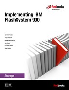
8.2.4 Verifying FlashSystem 900 connectivity in SAN Volume Controller
After you activate the zoning, you are to be able to identify the IBM FlashSystem 900 as a controller to SAN Volume Controller. You can use the SAN Volume Controller command lscontroller or the SAN Volume Controller GUI to navigate to Pools → External Storage to verify.
Change the controller name on the SAN Volume Controller system by one of two methods:
•Issue the SAN Volume Controller command chcontroller with the -name parameter
•Use the SAN Volume Controller GUI to navigate to Pools → External Storage and then right-click the controller that you want and select Rename.
After you change the name, you can easily identify the IBM FlashSystem 900 as a controller to SAN Volume Controller as shown in Figure 8-5.

Figure 8-5 IBM FlashSystem 900 as an external storage to SAN Volume Controller
You also need to create zones between SAN Volume Controller and the host. For guidance to configure zoning for host access to SAN Volume Controller, see IBM System Storage SAN Volume Controller and Storwize V7000 Best Practices and Performance Guidelines, SG24-7521.
IBM FlashSystem 900 host and volume creation
To provide usable storage (managed disks) to SAN Volume Controller, the IBM FlashSystem 900 must have volumes defined. These volumes must be mapped to the SAN Volume Controller host that also must be created. For guidance to perform these steps, see Chapter 6, “Using IBM FlashSystem 900” on page 161.
Create one host and name it, for example, SVC. Then, add the SAN Volume Controller worldwide port names (WWPNs) that will communicate with the FlashSystem (in this case, SAN Volume Controller nodes port 1 and port 5) to this newly created host. Then, create the volumes following the guidelines described in the next topic and map them to this newly created host called SVC.
SAN Volume Controller managed disk configuration
The preferred practices and considerations to design and plan the SAN Volume Controller storage pool (MDisk group) setup using the IBM FlashSystem 900 are described. There are several considerations when planning and configuring the MDisks and storage pools for the IBM FlashSystem 900 behind the SAN Volume Controller.
When using the IBM FlashSystem 900 behind the SAN Volume Controller, it is important to note the following points when planning to design and create MDisks for use in storage pools. In this case, the queue assignment and cache assignment are not as relevant as they are with traditional spindle-based disk systems because of the rapid speed with which the IBM FlashSystem 900 is able to process I/O requests.
It is advised to use MDisks in multiples of 4, which is an optimal number for CPU processing, because the MDisks and extents will be equally distributed to the SAN Volume Controller CPU cores.
The second CPU with 32 GB memory feature on SAN Volume Controller Storage Engine Model DH8 provides performance benefit only when Real-time Compression is used. IBM intends to enhance IBM Storwize Family Software for SAN Volume Controller to extend support of this feature to also benefit uncompressed workloads.
Storage pool extent size
When you work with an all IBM FlashSystem 900 behind a SAN Volume Controller configuration, the extent size can be kept at the default2 value of 1024 MB (1 GB). The performance of the IBM FlashSystem 900 with random I/O workload does not require the extent size to be smaller. The maximum extent size is 8,192 MB which provides for a maximum Mdisk of 1,024 TB or one petabyte.
If there are existing systems and storage pools, you must have the same extent size for all pools to use transparent volume migration between pools. If you have different extent sizes, you can use volume mirroring to create a copy of the disk and then promote it to the master volume when the copy is completed. However, this manual process takes slightly longer to complete.
All FlashSystem versus mixed storage pools
If you use the FlashSystem 900 as the primary data storage, add all of the MDisks from the controller to a single managed disk group (also know as a storage pool in the SAN Volume Controller GUI). However, if more than one FlashSystem 900 is presented to a SAN Volume Controller cluster, a preferred practice is to create a single storage pool per controller.
If you use the FlashSystem 900 with the SAN Volume Controller Easy Tier function, you likely want to create multiple volumes for each hybrid storage pool. Create four or more volumes for each hybrid pool, with the combined capacity of these volumes matching the capacity that you want for the SSD tier in that pool. More information about SAN Volume Controller Easy Tier with the FlashSystem is in the next topic.
MDisk mapping, storage pool, and volume creation
This section describes mapping MDisks from an IBM FlashSystem 900 to SAN Volume Controller is defined. Defining a storage pool to accommodate those volumes and the process to provision a volume from the FlashSystem 900 storage pool to the hosts are also explained.
After volumes are created on the IBM FlashSystem 900 and presented to the SAN Volume Controller, they need to be recognized in the SAN Volume Controller. The first step is to click the Detect MDisks option from the SAN Volume Controller GUI to detect the newly presented MDisks, as shown in Figure 8-6. Use the following sequence to perform this operation (follow the arrows in Figure 8-6):
1. Select the Pools option.
2. Choose External Storage.
3. Click the Detect MDisks option.
4. When the task completes, click Close to see the newly available MDisks.
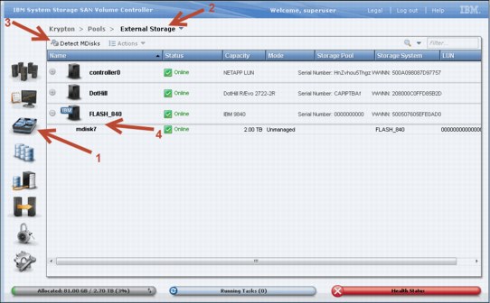
Figure 8-6 Detect MDisks option in the GUI
When this detection completes, a list of MDisks appears, as shown in Figure 8-6 (see mdisk7). It is important to rename the MDisks when they are added, for identification purposes. When naming an MDisk, the suggested naming convention is as follows:
%controller name_lun id on disk system%
This defines the name of the controller from which the LUN is presented and the local identifier that is referenced on the source disk system. This information is helpful when troubleshooting.
To rename an MDisk, select the MDisk that you want, right-click, and select Rename. A Rename MDisks window opens. Type the new names of the MDisks and then click Rename.
The next step is to create a new storage pool, if you want, as shown in Figure 8-7. A pop-up menu is displayed that you can use to configure the storage pool name and extent size. Ensure that Advanced Settings is clicked to show the extent size menu. The default is 1 GB (1024 MB), which can be left as the default, as explained in “SAN Volume Controller managed disk configuration” on page 296. You enter the name of the storage pool, and when complete, click Next.
Use the following sequence to perform this operation (follow the arrows in Figure 8-7):
1. Select the Pools icon.
2. Choose MDisks by Pools.
3. Click New Pool.
4. Enter the pool name and extent size that you want.
5. Click Next to advance.

Figure 8-7 The new pool option
The MDisk that will be in this storage pool needs to be added. Select the MDisk to be a member of this group, as shown in Figure 8-8, and then click Create.

Figure 8-8 Showing the MDisk candidate to include in the storage pool being created
The process begins, as shown in Figure 8-9. Click Close when completed to return to the main page.
Figure 8-9 Command to create a storage pool being processed
After the command completes, the storage pool is created and the MDisk is a member of the storage pool. To confirm, review the details of the new storage pool just created, as shown in Figure 8-10.

Figure 8-10 Checking storage pool details for the newly created pool
The definition of the MDisk and one storage pool is complete. If a second storage pool is necessary for volume mirroring or for more volume allocation, create the second storage pool by repeating the steps in these figures: Figure 8-7 on page 298, Figure 8-8 on page 299, Figure 8-9 on page 299, and Figure 8-10.
|
Suggestion: Add all MDisks to the defined storage pool at creation time, or before starting volume allocation on that pool. You can select more than one MDisk candidate during the storage pool creation process, or you can add it manually by using the addmdisk command (or by using the GUI, also).
|
Now that you have an available storage pool, you can create a host. Assuming that zoning is already configured between the host and SAN Volume Controller, Figure 8-11 shows the main menu to create a host on SAN Volume Controller. Use the following sequence to perform this operation (follow the arrows in Figure 8-11):
1. Select the Hosts icon.
2. Click Hosts.
3. Click New Host.
4. Select the Fibre Channel port to be added to that host.
5. Click Add Port to List.
6. Check the Port Definitions to ensure that you added the port.
7. Click Create Host to complete the process.

Figure 8-11 The New Host option
After you create the host, you can now create a volume (shown in Figure 8-12). Note that the selected pool is the FlashSystem 900 pool that you created previously. Use the following sequence to perform this operation (follow the arrows in Figure 8-12):
1. Select the Volumes icon.
2. Choose Volumes.
3. Click the New Volume option.
4. Choose a volume preset. In this case, use the Generic icon.
5. Select a pool (in this case, use the FlashSystem pool), and enter the quantity, capacity, and name in the Volume Details section.
6. Click Create to complete the process.

Figure 8-12 The New Volume option
The final step is to assign the recently created volume to the host that is already created. Use the following sequence to perform this operation (follow the arrows in Figure 8-13):
1. Select the Volumes icon.
2. Choose Volumes.
3. Select the volume that you want to map.
4. Click Actions.
5. Select the option Map to Host.

Figure 8-13 The Map to Host option
6. Another pop-up menu is displayed. Select the volumes that you want to map to the host (Figure 8-14). Click Apply to complete the assignment.

Figure 8-14 The Map to Host steps
The tasks on SAN Volume Controller side are complete. At this point, the server is able to recognize the volume, assuming that the server is already prepared in terms of multipathing software and HBA firmware.
SAN Volume Controller volume mirroring
The SAN Volume Controller volume mirroring feature allows the creation of one volume with two copies of its extents. The two data copies, if placed in separate storage pools, allow volume mirroring to eliminate the impact to volume availability if one or more MDisks, or the entire storage pool, fail.
When you design for a highly available SAN Volume Controller and FlashSystem deployment, a good approach is to have each storage pool that is built with MDisks come from separate back-end storage subsystems. This allows the mirrored volumes to have each copy in a different storage pool. In this manner, volume mirroring can provide protection against planned or unplanned storage controller outages because the volume continues to be available for read/write operations from hosts with the surviving copy.
SAN Volume Controller volume mirroring is a simple RAID 1-type function that allows a volume to remain online even when the storage pool backing it becomes inaccessible. Volume mirroring is designed to protect the volume from storage infrastructure failures by seamless mirroring between storage pools.
Volume mirroring is provided by a specific volume mirroring function in the I/O stack, and it cannot be manipulated like a FlashCopy or other types of copy volumes. However, this feature provides migration functionality, which can be obtained by splitting the mirrored copy from the source or by using the “migrate to” function. Volume mirroring cannot control back-end storage mirroring or replication.
With volume mirroring, host I/O completes when both copies are written. Before version 6.3.0, this feature took a copy offline when it had an I/O time-out, and then resynchronized with the online copy after it recovered. With 6.3.0, this feature is enhanced with a tunable latency tolerance. This tolerance provides an option to give preference to losing the redundancy between the two copies. This tunable time-out value is Latency or Redundancy.
•The Latency tuning option, which you set with the chvdisk -mirrowritepriority latency command, is the default. This behavior was available in releases before 6.3.0. It prioritizes host I/O latency, which yields a preference to host I/O over availability.
•However, you might have a need in your environment to give preference to Redundancy when availability is more important than I/O response time. Use the chvdisk -mirror writepriority redundancy command.
Regardless of which option you choose, volume mirroring can provide extra protection for your environment.
Migration offers the following options:
•Volume migration by using volume mirroring and then by using Split into New Volume
By using this option, you can use the available RAID 1 functionality. You create two copies of data that initially has a set relationship (one volume with two copies: one primary and one secondary) but then break the relationship (two volumes: both primary and no relationship between them) to make them independent copies of data. You can use this to migrate data between storage pools and devices. You might use this option if you want to move volumes to multiple storage pools. Volume can have two copies at a time, which means you can add only one copy to the original volume and then you have to split those copies to create another copy of the volume.
•Volume migration by using Move to Another Pool
By using this option, you can move any volume between storage pools without any interruption to the host access. This option is a quicker version of the previous option (volume mirroring and Split into New Volume). You might use this option if you want to move volumes in a single step or you do not have a volume mirror copy already.
|
Note: Volume mirroring does not create a second volume before you split copies. Volume mirroring adds a second copy of the data under the same volume; as a result, you have one volume presented to the host with two copies of data connected to this volume. Only splitting copies creates another volume and then both volumes have only one copy of the data.
|
With volume mirroring, you can move data to various MDisks within the same storage pool or move data between different storage pools. There is a benefit of using volume mirroring compared to volume migration: With volume mirroring, storage pools do not need the same extent size as is the case with volume migration.
Starting with firmware 7.3 and the introduction of the new cache architecture, mirrored volume performance is significantly improved. Now, lower cache is beneath the volume mirroring layer, which means each copy has its own cache. This helps in cases of having copies of different types, for example generic and compressed, because now each copy uses its independent cache and each copy can do its own read prefetch now. Destaging of the cache can now be done independently for each copy, so one copy does not affect performance of a second copy.
Also, because the Storwize destage algorithm is MDisk-aware, it can tune or adapt the destaging process, depending on MDisk type and utilization; this can be done for each copy independently.
Use cases: SAN Volume Controller volume mirroring with FlashSystem
Depending on the storage system chosen for each of the two volume mirror copies, certain details must be considered to meet the high performance and low latency expectations of the solution. This section describes usage scenarios for the SAN Volume Controller volume mirroring when virtualizing one or more FlashSystem storage systems, and the potential benefits and preferred practices for each scenario.
Use case 1: Volume mirroring between two FlashSystem storage systems
This case is the basic scenario for SAN Volume Controller volume mirroring because both copies reside on the same type of storage systems. In this scenario, there is no expected impact to performance in a failure if the two subsystems are close to the SAN Volume Controller nodes. This scenario indicates a non-stretched cluster setup. In this case, FC link latency is not likely to present an issue, and the default configuration for preferred node, primary copy, and mirroring priority is simplified.
Be careful to ensure a balanced workload between all the available resources (nodes, paths, fabrics, and storage subsystems).
However, if a SAN Volume Controller Stretched Cluster architecture is deployed in this scenario, plan carefully to ensure that the link latency between the SAN Volume Controller nodes, the hosts, and the two FlashSystem subsystems does not negatively affect the I/O operations from the applications.
Follow these suggestions, when possible:
•The preferred node for each mirrored volume needs to be kept at the same site as the subsystem that contains the primary copy of that mirrored volume.
•The host that is performing the I/O operations to the mirrored volume needs to reside in the same site as the preferred node for that volume.
•The -mirrorwritepriority flag for the mirrored volume must be set to latency if the access to the volume copy across the stretched cluster link represents a significant percentage of the total I/O latency. This can compromise the cache usage. Otherwise, the suggested value of redundancy still applies for every stretched cluster architecture to offer the highest level of data concurrency at both sites for protection against failure in the environment.
|
Note: If the primary purpose of the vdisk copy is data migration, then the mirror write priority should be set to latency. If, however, the primary purpose of the mirror is to provide protection against storage failure, the option should be set to redundancy.
|
Use case 2: Volume mirroring between a FlashSystem and a non-flash storage system
In this scenario, usually adopted for cost-reduction reasons, plan to avoid the penalty that is represented by the slowest subsystem to the overall I/O latency. Follow these suggestions:
•The primary copy of each mirrored volume must be set for the copy that resides in the FlashSystem subsystem so that all the reads are directed to it by SAN Volume Controller. This configuration is commonly referred to as a preferred read configuration.
•If both subsystems are close to the SAN Volume Controller nodes, a non-Stretched Cluster setup, the -mirrorwritepriority flag for the mirrored volume needs to be set to latency. Therefore, destaging to the volume copy in the slowest subsystem does not introduce a negative impact in the overall write latency and, consequently, to cache usage.
Using the FlashSystem with SAN Volume Controller Easy Tier
In this scenario, the IBM FlashSystem 900 is used with SAN Volume Controller Easy Tier to improve performance on a storage pool. Because of the complexity of this scenario, there are important considerations when you design and plan to add a FlashSystem to an existing environment.
A common question is when to use the FlashSystem storage over internal solid-state drives (SSDs) in SAN Volume Controller. The suggestion is to use the FlashSystem storage when your capacity requirements for Easy Tier exceed five SSDs. At this point, consider the FlashSystem storage systems for cost efficiency and performance. For more information, see Flash or SSD: Why and When to Use IBM FlashSystem, REDP-5020.
When planning to use the FlashSystem 900 with SAN Volume Controller Easy Tier, first use the IBM Storage Tier Advisor Tool (STAT) to obtain a comprehensive analysis of hot extents. This will allow you to estimate the amount of required FlashSystem capacity. For more information about using this tool, see Implementing the IBM System Storage SAN Volume Controller with IBM Spectrum Virtualize V7.6, SG24-7933.
Ensure that you add these MDisks as SSD MDisks; otherwise, SAN Volume Controller Easy Tier cannot distinguish between the spindle-based generic hard disk drives (HDDs) and the FlashSystem SSD MDisks. This task can be done by first creating the new Mdisks and then change tier level using the chmdisk -tier ssd <mdisk> command after adding the MDisks to a storage pool.
FlashSystem with SAN Volume Controller replication
Consider the following information when you use the IBM FlashSystem 900 with the SAN Volume Controller and replication:
•Additional latency overhead with synchronous Metro Mirror
•Distance of cross-site links and additional latency overhead
•Adequate bandwidth for cross-site links
•Amount of data to replicate and its I/O rate
•Dedicated replication ports
The IBM FlashSystem storage systems provide extremely low latency. The latency of Metro Mirror links might affect the FlashSystem storage systems to a greater degree than other traditional disk systems used with SAN Volume Controller. Metro Mirror replication distances in excess of 10 km (6.2 miles) must be carefully analyzed to ensure that they do not introduce bottlenecks or increase response times when used with the FlashSystem storage systems.
|
Tip: Dedicating ports for replication is strongly advised with this solution. Isolating replication ports can disperse congestion and reduce latency for replication, while protecting other ports from the impacts of increased amounts of replication traffic.
|
FC is the preferred connectivity method using a Dense Wavelength Division Multiplexer (DWDM), or equivalent device, between the source and target sites. Furthermore, the use of inter-switch links (ISLs) in a trunk or port channel to increase the aggregate bandwidth between the two sites is advised. Also, size the connectivity between sites according to the amount of bandwidth that you are allocating on SAN Volume Controller for replication, with additional bandwidth for future growth and peak loads. To summarize, consider the following factors when you design the replication connectivity:
•Current average and peak write activity to the volumes that you plan to replicate
•Desired recovery point objective (RPO) and recovery time objective (RTO) values
•Existing preferred practices for SAN Volume Controller replication (in IBM System Storage SAN Volume Controller and Storwize V7000 Replication Family Services, SG24-7574)
|
Note: When using Fibre Channel over IP (FCIP) for replication in this scenario, consider using at least 10 Gb links between sites.
|
8.2.5 Import and export
Import and export options are helpful if you use SAN Volume Controller as a migration device in the following ways:
•Import to Image mode
By using this option, you can import an existing storage MDisk or logical unit number (LUN) with its existing data from an external storage system without putting metadata on it so that the existing data remains intact. After you import it, all copy services functions can be used to migrate the storage to other locations while the data remains accessible to your hosts.
•Export to Image mode
By using this option, you can move storage from managed mode to image mode, which is useful if you are using the SAN Volume Controller as a migration device. For example, vendor A’s product cannot communicate with vendor B’s product, but you must migrate existing data from vendor A to vendor B. By using Export to image mode, you can migrate data by using Copy Services functions and then return control to the native array while maintaining access to the hosts.
8.3 Integration considerations: FlashSystem 900 and SAN Volume Controller
Figure 8-15 shows an example of a usage scenario that combines SAN Volume Controller and the IBM FlashSystem with a tiered approach to the storage management of a storage FlashSystem. In this solution, write I/O is performed to both the FlashSystem and disk storage for both VDisk Mirror copy 1 and copy 2. Read I/O is performed from the FlashSystem to boost performance with microsecond latency.

Figure 8-15 IBM FlashSystem and SAN Volume Controller tiered scenario with mirroring
8.4 Integration considerations: FlashSystem 900 and IBM Storwize V7000
IBM Storwize V7000 is a virtualized software-defined storage system that can consolidate workloads for simplicity of management, reduced cost, highly scalable capacity, performance, and high availability. This system offers improved efficiency and flexibility with built-in flash storage optimization, thin provisioning, and nondisruptive migration from existing storage.
A mid-range storage system, either a racked IBM Storwize V7000 or a chassis model (IBM Flex System® V7000 Storage Node), provides rich functionality and capacity. When you examine either type of storage node, which includes the usage of Easy Tier, you want to match a certain amount of fast storage with spinning storage. This is typically a 10:1 ratio. For example, if you wanted to achieve 100 TB of capacity with Easy Tier, you can get 90 TB of spinning capacity and 10 TB of flash capacity.
In the Storwize V7000, you can achieve 10 TB of capacity with SSDs in the controller or expansion unit, but if you price the solution, you might find that 10 TB of the FlashSystem 900 are more economical. To gain the maximum benefits in this solution, you can use the Storwize V7000 disk slots for the spinning disk capacity, and use the FlashSystem 900 as the fast tier.
Similar to SAN Volume Controller, the IBM Storwize V7000 offers the same functionalities, such as mirroring, FlashCopy, thin provisioning, Real-time Compression, and remote copy. All suggestions described in SAN Volume Controller section can also be applied to the V7000 integration.
Another similarity with SAN Volume Controller is that you can integrate the FlashSystem 900 with an existing Storwize V7000 environment and a bundled solution: the FlashSystem 900 plus the Storwize V7000. For more information about ordering these bundled solutions, contact IBM services, your IBM representative, or your IBM Business Partner for assistance.
For information about how to deploy the IBM Storwize V7000, see Implementing the IBM Storwize V7000 and IBM Spectrum Virtualize V7.6, SG24-7938 and Implementing the IBM Storwize V7000 Gen2, SG24-8244.
1 Compression data based on IBM measurements. Compression rates vary by data type and content.
2 Starting on SAN Volume Controller version 7.x
..................Content has been hidden....................
You can't read the all page of ebook, please click here login for view all page.