
Debugging the Interrupts
“Got a minute?” Cody asked as he dropped into the chair beside Matt’s desk.
“I showed the programmer to Josh and one of the marketing guys, and they want some changes that I’m not sure how to accomplish. They say that the messages are too slow during programming, it makes the system look sluggish. And they want to be able to send any command from a script file without worrying about the programmer falling behind and losing data.”
“Let’s take them one at a time,” Matt said. “How are your messages transmitted?”
Cody pulled several stapled sheets from a folder. “Here’s the pseudocode for the transmit portion of the background loop,” he said, pointing.
If UART Tx register empty (ready to transmit),
“So you do your transmitting from the background loop,” Matt said.
“Sure. I thought speedy transmitting was less important than getting the PROMs programmed.”
“But the way your code is structured, you can’t transmit more than one byte for every pass through the background loop. You also program one byte for each pass through the loop, and the loop doesn’t execute while a byte is programming. So if you are programming a chip that needs, on average, 5 milliseconds per byte, your maximum transmission rate is, um, 200 characters per second. No wonder it looks sluggish.”
“So I have to service the UART transmitter from the ISR just like the receiver, right?”
“That sounds like the best solution.”
“But my ISR is already too complicated. That’s why I have problems with executing back-to-back commands.”
“Do you execute your commands in the ISR?”
“Sure. And if it’s a fill buffer command that takes a while to execute, I miss the next couple of characters because they come in while I’m doing the fill.”
“I’d move the command processing to the background and make the ISR as simple as possible.”
Matt picked up a marker and wrote on the whiteboard:
New ISR
If UART Rx ready bit set (Rx data available),
Otherwise (there was no Rx data),
If the Tx FIFO read and write pointers are equal (FIFO empty),
The interrupts in an embedded system are, in many systems, the key to doing things in real time. They also add a level of complexity to the system that complicates the debugging process. Although they are sometimes the only way to make sure that a particular device or task is executed in a predictable fashion, they tend to make the overall system less stable and less predictable.
Interrupt Overview
An interrupt signals an external event to the microprocessor. It may indicate that a particular amount of time has elapsed, or that a user has pressed a button, or that a mechanical arm has moved another step. In general, interrupts are used to be sure that something gets serviced right away.
Let’s look at the programmer hardware as an example of the mechanics of servicing interrupts. When the UART receives a byte of data, it generates an interrupt on the 80188 INT0 pin. The 80188 internal interrupt controller sees the interrupt pin go active and interrupts the processor. The processor finishes executing the current instruction and then executes an interrupt acknowledge cycle, which is recognized by the interrupt controller. During the acknowledge cycle, the interrupt controller provides an interrupt vector to the 80188. The interrupt vector is a byte, and, in the case of the 80188 INT0, has a value of 12 (0C hex). The 80188 multiplies this by 4 to create a vector address, then gets an interrupt vector from the new address (00030 hex for INT0). The first 1k of memory, 00000 through 003FF, is the interrupt vector table for the 80188 and contains interrupt vectors for the various interrupts. In the case of INT0, locations 00030 through 00033 contain a pointer to the UART ISR in the EPROM. The processor saves the return address (the next instruction that would have executed if the interrupt hadn’t occurred) and branches to the address it reads from the vector table. Figures 6.1 and 6.2 show the 80188 interrupt sequence.

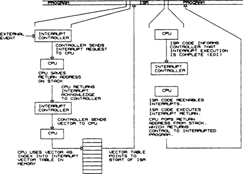
The ISR saves the CPU context and any registers that it will use, does whatever it needs to do to handle the interrupt, and then informs the interrupt controller that the interrupt has been serviced. This is necessary because the interrupt controller remembers which interrupt is in process and will not permit another one to be serviced until it has been told that the previous interrupt was serviced. The CPU context is defined as the current state of the CPU (flags, condition codes, etc.).
The last thing the ISR must do is restore the state of the CPU to whatever it was before the interrupt occurred. This means restoring the saved registers and reenabling interrupts. The CPU disables interrupts during interrupt servicing, so the ISR must tell the CPU when to turn interrupts back on. This is the End of Interrupt (EOI).
If everything was done right, the CPU will resume execution at the place it left off when the interrupt occurred, as shown in Figure 6.2, and that section of code will not even know the interrupt happened.
It is important to note the difference between the interrupt input and the interrupt to the CPU. To illustrate this, Figure 6.3 shows an 8088 processor using an 8259 interrupt controller. The 8259 accepts up to eight external interrupt inputs. But the 8259 provides only one interrupt input to the CPU. When a device requests an interrupt, the 8259 generates an interrupt to the CPU and then gives the CPU a vector when the CPU performs an interrupt acknowledge cycle. The vector is based on which interrupt input is active.

The peripheral that generated the interrupt does not know when the CPU is interrupted or when the interrupt acknowledge occurs. The first time the peripheral knows that its interrupt has been handled is when the ISR services the hardware. In fact, if the interrupts are prioritized, an interrupt from a low-priority peripheral may not be serviced for a while, if a higher priority interrupt is in progress.
The 80188, just described, has several interrupt inputs, both from external and internal sources. The CPU core, however, still gets a single interrupt and a vector from an internal controller.
Since the interrupt vector table is usually in RAM memory, the CPU must write the vector table before the first interrupt occurs. In the case of the programmer software, a copy of the interrupt vector table is stored in PROM and is copied to RAM after powerup reset before interrupts are enabled for the first time.
Some processors, such as the 8031, do not use a vector table. Instead, an interrupt sends the processor to actually execute code at a particular address, as shown in the following table:
8031 Interrupt Addresses
| Interrupt Source | Vector Address (hex) |
| I0 | 0003 |
| Timer 0 | 000B |
| I1 | 0013 |
| Tuner 1 | 001B |
| UART/USART | 0023 |
These memory locations would typically contain a branch instruction that jumps to the actual ISR somewhere else in ROM, although a very simple ISR might fit in the 8-byte interrupt address.
Some processors, such as the Z-80 family, allow an instruction to be presented to the processor during the interrupt acknowledge cycle. This will typically be a 1-byte software interrupt instruction that has the same effect as an interrupt vector.
Interrupts come in two flavors: edge and level sensitive. Edge sensitive interrupts are activated when a signal changes state. An edge sensitive interrupt typically must change from the inactive state to the active state, then be held in the active state until serviced. A level sensitive interrupt will be serviced as long as it is in the active state. Some processors, such as the 80188 and 8051, have external interrupts that can be programmed to be either level or edge sensitive.
Interrupts on some processors can be prioritized. When prioritizing is used, a high-priority interrupt can interrupt the ISR for a lower-priority interrupt, but not vice versa. Methods for prioritizing interrupts, and the flexibility those methods provide, vary from processor to processor.
Interrupts are asynchronous: they can occur at any point in code execution. Even a regular interrupt, such as a timer tick, is asynchronous with respect to the rest of the code. This one fact is probably, directly or indirectly, responsible for most of the difficult problems in interrupt-driven systems.
Debugging Interrupts
The traditional tools for debugging software are less useful for debugging interrupt problems. The most common tool for users of emulators or ROM monitors is the breakpoint. When a breakpoint is executed, the processor stops or transfers control to the monitor program. The problem is that interrupts keep coming, and they stack up. As soon as you try to step the code or resume execution, all those stacked interrupts want attention at once. All the hardware events they represent occurred several seconds or minutes ago. In addition, because interrupts are asynchronous, the actual cause of a problem may have occurred long before the symptoms you can trigger on.
Potential Interrupt Problems
The interrupt system is susceptible to all the hardware and software problems to which the rest of the system is susceptible, and also to some unique faults that occur nowhere else.
Stack Control
When the ISR is entered, it is usually necessary to save all the registers that will be used and restore them on exit. This is usually performed by pushing the registers onto the stack and popping them off before returning. Of course, the return address is also placed on the stack when the ISR is executed, so if there are more pushes than pops (or vice versa), the ISR will return to some unknown location. This condition is usually obvious—the processor just goes off “into the weeds” as soon as the interrupt is enabled. A less obvious condition is where the registers are popped in a different order than they were pushed. The following 80188 code fragment illustrates this:
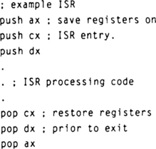
In this case, the registers were pushed in the order AX, CX, DX, but popped in the order CX, DX, AX. This has the effect of swapping the contents of CX and DX when the ISR returns. The symptom this produces can be very subtle. Let’s say that the background code doesn’t use DX or CX, but some seldom-used subroutine does. In this case, there may not be any problem until the ISR occurs during that subroutine. Or, suppose the same background code is modified so that it uses CX or DX. The new code will appear to have a bug, when it is actually the ISR that is causing the error.
Some designers get around this problem by using a standard save/restore macro that always saves all the registers. The only problem with this solution is that you may end up saving registers you don’t use in the ISR, and that takes time.
This problem is unlikely if the ISR is written in an HLL; the compiler takes care of saving and restoring the registers.
Shared Resources
This can be the cause of symptoms that are serious but difficult to isolate. This class of problems can be further divided into shared variables, shared I/O, and shared subroutines.
Shared Variables
Take a look at the two pseudocode fragments below:
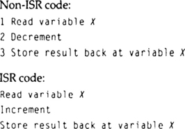
Let’s say that X is counting the number of bytes in some hypothetical buffer. The ISR code puts a byte in the buffer and increments the count to indicate the change. The non-ISR reads a byte from the buffer and decrements the count.
Say that X starts out with a value of 4. The ISR code puts a byte in the buffer and increments X to 5. The non-ISR code then reads a byte and decrements the count back to 4. But if the interrupt occurs while statement 2 in the non-ISR code is executing, the value of X will be corrupted. First, the non-ISR code reads X, which is 4. Then the ISR occurs and increments X to 5. After the ISR completes, the non-ISR code finishes, and stores 3 in the buffer.
A similar problem can occur with binary variables (semaphores) used to control access to some common resource, such as a printer. Say that the variable FLAG indicates availability of the printer. If FLAG is cleared, the printer is available and any subroutine in the code can use it. The subroutine that wants the printer must set FLAG to tell all other subroutines that the printer is in use, and resets FLAG when finished with the printer so that other subroutines can have it. Now look at the following pseudocode:

Both the ISR and non-ISR code use the same logic to get control of the printer. If the interrupt occurs between statements 1 and 2 in the non-ISR code, both the ISR and the non-ISR code will think they have control of the printer, and a conflict will result.
This problem has several solutions. Some processors have a test-and-set instruction that allows semaphores (such as FLAG in the second example) to be safely modified. These instructions will typically read the memory location, test/set the appropriate bit, then write the new value to the memory location. The instructions are typically locked or indivisible, meaning that the instruction, once it begins execution, will complete regardless of interrupts, DMA requests, and other external events.
A second solution to this problem is to disable interrupts around the read/test/write sequence in the non-ISR code, as illustrated below:

The simplest solution, and recommended whenever possible, is simply to avoid shared variables. To illustrate how this might work in the first example above (the buffer problem), let’s replace variable X with two pointers, a read pointer and a write pointer. Both pointers start out pointing to the beginning of the buffer. As the ISR puts bytes in the buffer, it increments the write pointer. To find out whether there is something in the buffer, the non-ISR code tests the pointers to see whether they are equal; if they are, the buffer is empty. If the pointers are unequal, the non-ISR code reads a byte and increments the read pointer.
Although this is a simplified explanation and leaves out some things (what do you do when one of the pointers gets to the end of the buffer?), it serves to illustrate the concept. Note that the ISR and non-ISR code never write the same pointer. This prevents the conflicts that occur with the shared variable. The PROM programmer code uses this method to handle UART receive and transmit data.
Even if the non-ISR code never writes a variable that is written by the ISR code, it is possible to have a sharing conflict. Look at the following pseudocode:
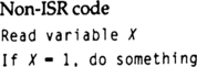
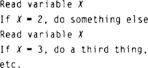
If the variable X were controlled by the non-ISR code, this code would do only one thing each time it executes, based on the value of X. However, if the variable X is set in an ISR, and if the interrupt occurs while this chunk of non-ISR code is executing, bizarre and apparently impossible results may be seen, since two of the “somethings” may be performed in one pass of the code. Since X is read every time it is tested, it can be changed by the ISR between the beginning and the end of the routine.
This problem is not as unlikely as it may appear. The 8031 microcontroller, for example, does not have a compare instruction. If X were a byte variable to be compared with three constants, the code would have to load X into the accumulator register and perform a subtract or exclusive-OR operation. Either of these alters the contents of the accumulator, so it must be reloaded before being tested again. Also, some compilers can create this sort of problem.
The fix is obvious; if you are reading a variable that is set by an ISR, and you need to use it more than once outside the ISR, read it once and store it in a temporary location, then use the copy.
Shared I/O
This problem is similar to the shared variable problem, but may be more difficult to solve. Figure 6.4 shows a control register used in the programmer example. This 8-bit register provides six control bits to the PROM programming connector and also controls the bicolor LED.

Let’s say that the LED is controlled by an ISR while the control bits are managed by non-ISR code. Since this is a write-only register, a mask byte, which we’ll call CMASK, must be stored in memory. If the ISR wants to set the LED green, it might use the following code:

Now, suppose the non-ISR code wants to set the CE output low. It might do this:

Now we have a problem similar to the shared variable problem. If the interrupt occurs between the non-ISR read of CMASK and writing the modified value to CMASK, the LED will flicker briefly green (probably too fast even to see the flicker), then revert to whatever it was before the ISR tried to change it.
There are a couple of fixes for this problem: the most obvious is to disable/enable interrupts around the non-ISR CMASK/LED register update. Another solution would be to define a second mask variable, which we’ll call LEDMASK, for the LED only. Then our pseudocode looks like this:

The drawbacks to this are that the LED color changes only when the non-ISR code changes one of the other control bits, and you always have to remember to include the value in LEDMASK when updating the control register.
A similar solution would be to create CONTROLMASK instead of LEDMASK and have the non-ISR code update this variable, but not update the control register. The ISR code would then keep the LED value in MASK, and update the LED register, including the value in CONTROLMASK. This, of course, reverses the problem in the previous solution: the non-ISR code cannot update the control bits immediately but must wait until the next ISR update of the LED register.
Some peripheral ICs, such as the Zilog Z8530 (serial communication controller) and Z8536 (timer/counter/parallel I/O), have more internal registers than they have external addresses. Registers in these devices are manipulated by first writing a value to an internal address register, and then reading or writing data to a different address to access the selected register. Figure 6.5 shows a simplified block diagram of how these devices are structured.

Pseudocode to access a register in these devices looks something like this:
![]()
A problem occurs if an interrupt happens between the above two operations, and if the ISR also must manipulate the peripheral device. The non-ISR code will set the address register to select whatever data register it needs to access. Then the ISR gets control and accesses some register. Then the ISR returns and the non-ISR code completes its access, but now the address register has changed, so the non-ISR code reads (or writes) the wrong register.
Devices that have this characteristic are typically high-integration parts with a number of functions, and there may be no way to avoid having both ISR and non-ISR code access the device. In this case, the only reliable solution is to bracket the non-ISR access with an interrupt disable/enable pair.
Shared Subroutines
The PROM programmer that Cody is building has a subroutine that converts hex data to ASCII for display. Data is passed to this routine through a global variable, HEX. The subroutine puts the resulting ASCII in a global variable, ASC. Now, suppose that this is used by both ISR and non-ISR code. Then suppose that it has been called by non-ISR code, and then the ISR that uses the subroutine is activated by its interrupt.
When this happens, the ISR code will write to HEX whatever data it wants converted, call the conversion subroutine, and then read the result from ASC. When it returns, the values of HEX and ASC have been corrupted (as far as the non-ISR code is concerned), and the wrong values will be returned. This is a software version of the address/data register problem just described.
Unlike the hardware registers, this problem can be solved without disabling interrupts. The straightforward solution is to make the conversion subroutine reentrant, passing the hex input data and the ASCII return data on the stack. Any local variables must also be dynamic, meaning they, too, are stored on the stack (or in memory that is allocated each time the subroutine is called). This way, when the subroutine is interrupted and called again by the ISR, the original input data and any half-completed output data will be saved on the stack.
Some microcontrollers, such as the 8031, have a limited stack that makes normal reentrancy impossible. One solution to this is to have a register that points to a data area where the input and output values reside, and where space is allocated for any temporary variables needed by the conversion subroutine. The ISR then saves this register on entry, calls the subroutine, and restores the register on exit. As long as the ISR and non-ISR code don’t try to use overlapping data areas, the data will be preserved.
Interrupt Stackup
Interrupt stackup problems can take three forms: latency problems, stack overflow problems, and execution delays.
Latency is the time from when an interrupt occurs until it actually gets serviced. In general, it is best to assume that, at some point in the execution of your code, you will have all interrupts occur at the same time. The result of this is that the delay in returning to the non-ISR code will be total execution time of all the interrupts, as shown in Figure 6.6. Here we have a system with three interrupts. Interrupt 1 occurs first, and while interrupt 1 is executing, interrupt 2 occurs. As soon as the ISR for interrupt 1 is finished, the ISR for interrupt 2 executes. A similar sequence occurs for the third interrupt. The result is that the background code does not get control again until all three ISRs have completed. Note that the three interrupts did not have to occur at the same time to become stacked.

If you believe you have latency problems, you can determine the latency for any given interrupt, if it is level-sensitive. Level-sensitive interrupts are asserted by some event and then cleared by the ISR, usually by reading/writing hardware. Thus the interrupt is active from the time it is asserted until it is serviced. Connecting a DSO set for repetitive mode to the interrupt line and triggering the DSO when the interrupt signal goes to the active state will give you a good picture of the minimum and maximum latency. Each new interrupt will trigger the DSO, which will overlay the new pulse width on the existing display. Extremely long latencies will show up as a very long pulse width. The one caveat to this method is that the DSO will take some time to paint the screen and may miss interrupts that occur during the screen update.
The latency of servicing an interrupt is only half the issue: in most cases, the interrupt condition is cleared early in the ISR, but there may be considerable processing in the ISR after that point. It is often useful to know how long the ISR takes.
Measurement of the entire ISR service time can be accomplished by adding a hardware trigger just before the ISR exit. This can consist of setting, then clearing, a port bit on a microcontroller or on a PIO chip, setting/clearing a spare bit in a hardware register, or writing/reading an unused location that will strobe the output of an I/O address decoder. To use this method, connect one channel of the DSO to the interrupt line, as before, and connect the second channel to the hardware trigger. Now when the interrupt occurs, the hardware trigger will indicate when the ISR is completed.
Some processors have internal peripherals that can generate interrupts. Examples of this are the timers and DMA channels on the 80188, and the timers on the 8031. Often these peripherals do not provide an interrupt signal outside the chip so that the latency can be measured. The execution time of the ISR, however, can still be measured. To do this, two hardware triggers are needed, one at the beginning of the ISR and one at the end. On a microcontroller, PIO chip, or hardware register, you can set a bit at the beginning of the ISR and clear it at the end. The DSO, again in repetitive mode, is used to capture the width of the pulse, which corresponds approximately to the execution time of the ISR.
Limited Stack
Some processors have a limited, fixed stack. The PIC17C42, for example, has a stack limited to 16 levels. If the total of your subroutine calls and ISRs exceeds this, the stack will overflow. Since the return addresses on the stack all point to valid code somewhere, the code will not necessarily go berserk.
The 8031 family of processors has stack limitations of a different type. The stack on an 8031 is in memory, so the stack is limited only by memory size. However, the internal memory on an 8031 is very limited, so it is easy to have the code grow down into the variable area and overwrite data.
If you suspect problems with stack size limitations, you might want to check the stack pointer in each ISR when it is called (on processors where you can get to the stack pointer). If you find the stack pointer at the end of the stack, set a port bit or send an action code, or do something to let the rest of the world know about the problem. A better solution is to assume that an interrupt will occur while you are at the deepest level of subroutine calls, and calculate what the result will be on the stack pointer. Fortunately, processors with extreme stack limitations are typically used in less complex applications, where it is easier to predict what the stack will do.
UART Transmit Lockup
Let’s look at the code for the UART transmitter in the programmer:
The UART itself has a bit in a hardware register, TIENAB, that allows the UART interrupt output signal to go active when the transmit register is empty.
The UART transmit code is divided into two portions: a subroutine called SNDMSG, and the UART ISR code. SNDMSG is called with a pointer to the message to be sent. Messages are terminated with a byte of 0FFh. A simplified description of SNDMSG might look like this (TWPOINT is the Tx FIFO write pointer):
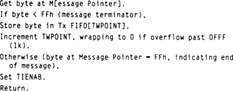
The transmit portion of the UART ISR looks like this (TRPOINT is the Tx FIFO read pointer):

Now we’ll analyze this briefly. The 16550-type UART used in the programmer is typical of UART ICs. It has a single interrupt output pin that is shared between receive and transmit. The software can enable and disable interrupts for either receive or transmit. If both interrupts are enabled, the interrupt pin will be active for either receive or transmit ready, and the software must read a register in the UART to determine which condition is causing the interrupt.
The receive interrupt function is straightforward—the interrupt is active when a new byte is in the receive holding register, and it stays active until the software reads the byte. The receive interrupt can typically be enabled all the time, since it generates an interrupt only when data is actually available.
The transmit interrupt is a different story. The transmit interrupt indicates when the UART is ready to accept data, whether there is any data to be sent or not. The default state of the transmitter, when it is idle, is to generate an interrupt. But the software needs to get an interrupt from the transmitter only when the UART is ready for data and when there is data to send. Otherwise, when there is no data to send, the interrupt signal will be continuously active and the software will spend all its time servicing the interrupt.
The way around this is to enable the transmit interrupt when there is data to send and disable it when all the data has been sent. But this requirement causes a potential problem. The non-ISR code must set the TIENAB bit and the ISR must clear it when a message is finished transmitting. So a potential race condition can exist. In the programmer, this is handled two ways:
1. The transmit buffer is a FIFO. The ISR code checks for data in the FIFO by checking for inequality between the read and write pointers. Since the write pointer for new data is set up well before the instruction that sets TIENAB, the ISR won’t find the buffer going empty just as a new message is placed there.
2. The non-ISR code sets TIENAB when done loading a message, without checking it first. This prevents a race condition that could occur if the transmit interrupt occurs between the test and the set operations. TIENAB is a bit in a UART hardware register, so writing a one when it is already a one will not cause problems.
Potential problems with any hardware, such as a UART, that needs control of an interrupt enable bit include:
• A race condition between test and set of the enable bit in the non-ISR code
• The receive interrupt enable and possible other enable bits (such as modem control) may be shared in the same UART register as the transmit enable bit. If the other bits are sometimes turned off, the code cannot set the transmit bit without reading the register (or a mask of it) and ANDing or ORing the new value in. The time between read and write has the potential for a race condition.
• Even with the arrangement used in the programmer, there is the potential for a problem if the message to be sent is very short (say, 1 byte) and the transmit ISR occurs before SNDMSG sets TIENAB. The ISR would see 1 byte in the FIFO, clear TIENAB, and return. SNDMSG would then set TIENAB even though the FIFO is now empty. To prevent this problem, the transmit ISR clears TIENAB if it finds an empty FIFO.
Interrupt Time
Most of the potential interrupt problems we’ve looked at have involved resources that are shared between the ISR and non-ISR code. It is possible for an interrupt to create problems completely unrelated to anything the ISR does or any resource it uses (except one).
Figure 6.7 shows how the asynchronous nature of interrupts can affect code that is unrelated to the interrupt. Here we have a timer IC, such as the 8253, connected to a processor. The gate input to the timer is controlled by 1 bit of a PIO IC or a register. When the gate is high, the timer increments, and when it is low, the timer holds the current count. The 16-bit timer is counting some external event, such as motor encoder pulses, regular ticks from another timer, or maybe items moving down a conveyor belt. Our hypothetical system also has an interrupt that is completely unrelated to the timer operation.

Figure 6.7 Interrupt Time Usage. The ISR execution time causes problems with a completely unrelated function.
As shown in the figure, the non-ISR code, for whatever reason, wants to read the timer contents. The problem with timers is that they may increment while reading, and the processor may end up with a mix of the old and new bits. So our non-ISR code uses the gate to stop the timer while reading the count.
As can be seen in the timing diagram, if the interrupt occurs during this read, and the ISR does not return until after the next external event occurs, a count is missed.
To fix this, we try leaving the gate active all the time and just reading the high and low bytes separately. Now a different problem is introduced. The processor reads the low byte of the count (32FF), and gets FF. Then the interrupt occurs, and after the ISR, the processor reads the high byte of the count (now 3300) and gets 33. The assembled word is now 33FF, completely incorrect.
The fix for this is to use a timer that will allow you to freeze the count in a separate register, or to read the low/high pair twice and compare them. More important, though, is this point: any time you have an interrupt-driven system with operations that are divisible but should not be, you have the potential for problems, because there is one global resource that all interrupts must use—time.
Prioritizing Interrupts
Nearly all systems have interrupts of different priorities. The 80188, for example, has several internal interrupt sources with differing priorities. It is not uncommon for a software design to leave interrupts disabled while in an ISR. In this scheme, a high-priority interrupt that is asserted at the same time as a low-priority interrupt will be serviced first. But a high-priority interrupt that occurs after a low-priority interrupt is acknowledged will be held off until the low-priority ISR is completed. This has the effect of making the low-priority ISR a higher priority.
In some systems, this is unacceptable. For example, you might have a processor that gets a continuous data stream from an RS-232 interface and also sends data to a printer. You would probably set the RS-232 receive interrupt to be a higher priority than the printer interrupt because you cannot afford to miss any serial data, but it’s okay for the printer to run slow sometimes. If the printer ISR for some reason takes longer than the time needed to receive a serial byte, then the printer ISR can cause missed data.
The solution is to add an additional level of prioritization called interrupt nesting. In interrupt nesting, an interrupt can itself interrupt the ISR of another interrupt of a lower priority. In our example, the RS-232 ISR would be higher priority than the printer ISR.
To implement interrupt nesting, you need an interrupt controller that can support it. Different processors and interrupt controllers support nesting to various degrees. The 8018x processors do support this feature with the internal controller. The commonly used 8259 interrupt controller also supports nesting. The 8031 processor supports two levels of priority for nesting. The 68000 family parts (which we’ll talk about later) has a prioritizing scheme that makes nesting nearly automatic.
The disadvantage to nested interrupts is that the ISRs themselves become susceptible to the same problems with divisibility, shared resources, and time that the non-ISR code has. In addition, the potential for stack overflow increases with nested interrupts. If you use nested interrupts, it is more important than ever to minimize the ISRs, thereby minimizing ISR execution time.
Problems with Vectored Interrupts
Of course, all interrupt systems are susceptible to the problems already described. Here we’ll take a look at problems that are less general.
A system using several individual, prioritized interrupts (like that of Figure 6.3) can hang up with one interrupt never being serviced. If you find an interrupt that is not being serviced, first look to see if that particular interrupt line is always high. If not, the peripheral, whatever it is, is not requesting an interrupt. If the interrupt line is always high, suspect that the interrupt is masked or that there is a priority problem. Note that when interrupts are nested, if the interrupt controller thinks an intermediate interrupt is still being serviced, all lower priority interrupts are blocked, but all higher-priority interrupts will continue to be serviced.
Since each interrupt in an 80188 or 8259-type system has a priority, the ISR must tell the interrupt controller when it is finished servicing the interrupt. If the ISR fails to send the EOI to the controller, or gives the controller the wrong EOI code, a lower-priority interrupt may never be passed through, since the controller believes it is still servicing a higher-priority interrupt.
Daisy-Chained Interrupts
Figure 6.8 shows a block diagram of a microprocessor using daisy-chained interrupts. In a daisy-chained system, each peripheral has an interrupt output and two priority pins, priority in and priority out. The priority in pin on the highest-priority peripheral is tied to the active state. The priority out of that peripheral is tied to priority in of the next-lowest-priority peripheral, and so on. A common open-collector or open-drain interrupt line is driven by each peripheral.
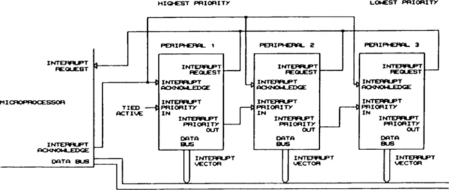
If any peripheral is not requesting an interrupt, its priority out follows priority in. If a peripheral is requesting an interrupt, priority in is blocked. A peripheral can assert the interrupt request only if its priority in is active.
The result of this is that the highest-priority device in the chain that wants to assert an interrupt will do so. Lower-priority devices that want to interrupt the processor must wait until all higher-priority devices have been serviced. When the CPU responds to the interrupt request with an acknowledge cycle, the requesting peripheral provides the interrupt vector.
The interrupt priority of each peripheral in a daisy-chained system is fixed and is determined by the position on the chain. The primary advantage of daisy-chaining is that there is no limit to the number of peripherals that can interrupt the processor. Disadvantages include the fact that interrupt priority is fixed, and the potential that a low-priority peripheral may not be serviced in a timely manner, or even at all.
The Motorola 68000-family processors add another feature to the daisy-chained structure. Motorola has three priority-encoded interrupt requests. A peripheral requests an interrupt by driving these lines to the requested priority level. If the priority lines contain a binary code greater than the current state of the processor, the interrupt will be serviced. The priority lines allow two levels of prioritization—the priority inherent in each daisy chain, and an overall priority level in multiple daisy chains. Or, the priority levels can be used by individual, non-daisy-chained peripherals.
If a daisy-chained peripheral is not being serviced, the first thing to do is look at the priority in. If this signal is always inactive, some higher-priority device is holding the priority off. This may be because the peripheral never received a valid EOI command after a previous interrupt.
If a daisy-chained peripheral gets serviced, but too late, you can look at higher-level priority out signals on a DSO or logic analyzer to see which higher-priority peripheral is holding things off too long. Of course, if you have a general throughput problem that prevents the peripheral from being serviced, you will not find a single priority out line that is holding things up.
In a 68000-type system, if things hang up, look at the encoded priority lines. If they are stuck in some state (or if a single line is stuck), the processor state is probably preventing the interrupts from being serviced. Look for an ISR or synchronization error that left the processor priority in the wrong state.
Shared Edge-Sensitive Interrupts
Sometimes it is necessary to have two devices share a single edge-sensitive interrupt. Although this should generally be avoided, you might have a situation where an interrupt controller (such as the 8259) requires that all interrupt inputs be edge- or level-sensitive (not individually programmable) and one or more peripherals requires an edge-sensitive interrupt.
Figure 6.9 shows how a shared edge-sensitive interrupt might become locked. Two devices, device 1 and device 2, share a single edge-sensitive interrupt line. The two devices might drive the line through an OR gate or through a wire-OR (open-collector) scheme.

In the figure, device 1 asserts the interrupt. While the software is servicing device 1, and before the interrupt condition is cleared, device 2 asserts an interrupt. Since there was no transition on the interrupt line, the interrupt controller does not recognize the second interrupt.
The fix for this is to have the ISR check for other interrupt request conditions after clearing the first interrupt. An alternative solution is to provide a gate in the common interrupt line so that the software can momentarily force the common interrupt line to the inactive state after clearing the first interrupt and sending the EOI to the controller. This will produce an inactive/active transition if a second device has requested an interrupt.
Missing Interrupts
Missing interrupts can take the form of missing data from a UART, from a motor that runs away because of missing encoder interrupts, or even from a system that crashes.
If you are using an external controller, you can sometimes catch a missing interrupt by connecting a logic analyzer to trigger when there are two interrupts without an interrupt acknowledge cycle between them. This works only if you have a single-interrupt system, or if you can set the analyzer up to determine which interrupt is being acknowledged.
If you are using edge-sensitive interrupts, toggle a port bit at the beginning of the ISR. If you see two interrupts without seeing the port bit between them, you’ve missed one.
A similar trigger can be accomplished by outputting an action code at the start of the ISR. Again, set the analyzer to trigger on two interrupts with no start-of-ISR action code between them. This will probably require a logic analyzer with the ability to mix state and timing triggers.
An Interrupt Status Circuit
In debugging interrupts, it is often useful to have a real-time status indication of which ISRs are in progress. This allows you, using a logic analyzer, to correlate the state of the interrupts with other system conditions (such as an error indication). As discussed earlier, if you are using a microcontroller, you can set a port pin at the start of the ISR and clear it at the end of the ISR.
If you are not using a microcontroller, or if you are using a microcontroller but have no spare port pins, the circuit in Figure 6.10 may be a useful tool.
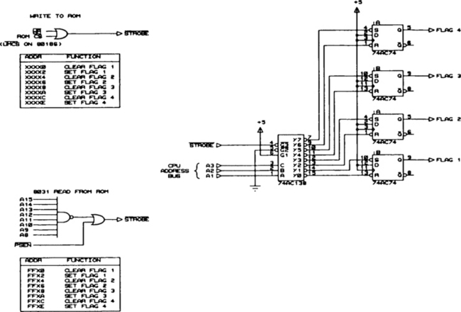
The circuit shown in the figure has four 74xx74 ICs wired as set/reset flipflops. Each flipflop represents one interrupt and is set or cleared by an output of a 74xx138 (3-to-8 decoder). The lower address lines from the CPU are used to select which flipflop will be set or cleared. The –STROBE input to the 74xx138, which enables the outputs, can be generated from a decoded I/O or memory select. The effect is to provide four bit-addressable port lines for indicating which ISRs are active.
Of course, the interrupt status could be stored in an 8-bit register. The advantage to this discrete flipflop design is that there is no need to maintain a mask of the register bits and no risk of race conditions while the mask and register are being updated. In operation, an ISR will, on entry, access the address that sets its flipflop. On exit, the flipflop is cleared. Neither operation affects the other flipflops in the circuit.
Also shown in the figure are two other methods of generating the –STROBE input to the 74xx138. The write-to-ROM circuit generates a strobe when writing to the ROM address space, and is suitable for use on processors with Intel-style read/write strobes. As with the write-to-ROM method described for action codes in an earlier chapter, make sure the ROM outputs are not enabled. The associated table shows which addresses generate which actions using this method.
The second enable circuit shown in the figure is suitable for an 8031-type processor or other Harvard-architecture processor that will not perform a write-to-ROM operation. In this case, a read from the upper 256 bytes of the ROM space generates the –STROBE signal. Again, the table shows which functions go with which addresses.
Although the circuit is shown with discrete logic, I would implement it in a PLD, which would also provide more than four outputs. When needed, the circuit could be clipped to the EPROM or connected to a header that brought out the required signals. The software can generate the set/clear strobes whether the circuit is connected or not, so no special version is needed for debugging.
Finally, when designing an interrupt system, remember the two immutable laws of interrupts:
Most of the problems illustrated in this chapter can be prevented by remembering the following rules:
Rule 1: Avoid any variable (hardware or software) that is written by both ISR and non-ISR code. Variables (and hardware registers) should be written by the ISR and read by the non-ISR code or vice versa.
Rule 2: Where shared variables (or hardware registers) cannot be avoided, identify and protect all non-ISR (and interruptible ISR) code that must be indivisible.
Rule 3: Always assume that ISR-modified variables will change between two successive reads.
Rule 4: In any system with multiple interrupts, at some point in time, all the interrupts will stack up. Count on it.
Rule 5: The real world keeps happening while interrupts are being serviced.
All the rules for non-ISR code apply to the ISR code as well, if nested interrupts are used.