Chapter Eleven. Troubleshooting and Supporting the Network
Objectives
4.6 Given a scenario, implement the following network troubleshooting methodology
![]() Information gathering—identify symptoms and problems
Information gathering—identify symptoms and problems
![]() Identify the affected areas of the network
Identify the affected areas of the network
![]() Determine if anything has changed
Determine if anything has changed
![]() Establish the most probable cause
Establish the most probable cause
![]() Determine if escalation is necessary
Determine if escalation is necessary
![]() Create an action plan and solution identifying potential effects
Create an action plan and solution identifying potential effects
![]() Implement and test the solution
Implement and test the solution
![]() Identify the results and effects of the solution
Identify the results and effects of the solution
![]() Document the solution and the entire process
Document the solution and the entire process
4.7 Given a scenario, troubleshoot common connectivity issues and select an appropriate solution
![]() Physical issues:
Physical issues:
![]() Cross talk
Cross talk
![]() Near End crosstalk
Near End crosstalk
![]() Attenuation
Attenuation
![]() Collisions
Collisions
![]() Shorts
Shorts
![]() Open impedance mismatch (echo)
Open impedance mismatch (echo)
![]() Interference
Interference
![]() Logical issues:
Logical issues:
![]() Port speed
Port speed
![]() Port duplex mismatch
Port duplex mismatch
![]() Incorrect VLAN
Incorrect VLAN
![]() Incorrect IP address
Incorrect IP address
![]() Wrong gateway
Wrong gateway
![]() Wrong DNS
Wrong DNS
![]() Wrong subnet mask
Wrong subnet mask
![]() Issues that should be identified but escalated:
Issues that should be identified but escalated:
![]() Switching loop
Switching loop
![]() Routing loop
Routing loop
![]() Route problems
Route problems
![]() Proxy ARP
Proxy ARP
![]() Broadcast storms
Broadcast storms
![]() Wireless Issues:
Wireless Issues:
![]() Interference (bleed, environmental factors)
Interference (bleed, environmental factors)
![]() Incorrect encryption
Incorrect encryption
![]() Incorrect channel
Incorrect channel
![]() Incorrect frequency
Incorrect frequency
![]() ESSID mismatch
ESSID mismatch
![]() Standard mismatch (802.11 a/b/g/n)
Standard mismatch (802.11 a/b/g/n)
![]() Distance
Distance
![]() Bounce
Bounce
![]() Incorrect antenna placement
Incorrect antenna placement
What You Need to Know
![]() Use troubleshooting steps to isolate and correct a problem.
Use troubleshooting steps to isolate and correct a problem.
![]() Identify and troubleshoot topology-specific errors.
Identify and troubleshoot topology-specific errors.
![]() Use troubleshooting techniques to identify and isolate client connectivity errors.
Use troubleshooting techniques to identify and isolate client connectivity errors.
![]() Use troubleshooting techniques to identify and isolate network wiring/infrastructure problems.
Use troubleshooting techniques to identify and isolate network wiring/infrastructure problems.
Introduction
Many duties and responsibilities fall under the umbrella of network administration. Of these, one of the most practiced is that of troubleshooting. No matter how well a network is designed and how many preventive maintenance schedules are in place, troubleshooting will always be necessary. Because of this, network administrators have to develop those troubleshooting skills.
This chapter focuses on all areas of troubleshooting, including troubleshooting best practices and some of the tools and utilities you’ll use to assist in the troubleshooting process.
Troubleshooting Steps and Procedures
Regardless of the problem, effective network troubleshooting follows some specific steps. These steps provide a framework in which to perform the troubleshooting process. When you follow them, they can reduce the time it takes to isolate and fix a problem. The following sections discuss the common troubleshooting steps and procedures as identified by the CompTIA Network+ objectives:
1. Information gathering: identify symptoms and problems.
2. Identify the affected areas of the network.
3. Determine if anything has changed.
4. Establish the most probable cause.
5. Determine if escalation is necessary.
6. Create an action plan and solution identifying potential effects.
7. Implement and test the solution.
8. Identify the results and effects of the solution.
9. Document the solution and the entire process.
Information Gathering: Identify Symptoms and Problems
The first step in the troubleshooting process is to establish exactly what the symptoms of the problem are. This stage of the troubleshooting process is all about information gathering. To get this information, we need knowledge of the operating system used, good communication skills, and a little patience. It is very important to get as much information as possible about the problem. You can glean information from three key sources: the computer (in the form of logs and error messages), the computer user experiencing the problem, and your own observation.
After you have listed the symptoms, you can begin to identify some of the potential causes of those symptoms.
Identify the Affected Areas of the Network
Some computer problems are isolated to a single user in a single location; others affect several thousand users spanning multiple locations. Establishing the affected area is an important part of the troubleshooting process, and it often dictates the strategies you use to resolve the problem.
Problems that affect many users are often connectivity issues that disable access for many users. Such problems often can be isolated to wiring closets, network devices, and server rooms. The troubleshooting process for problems that are isolated to a single user often begins and ends at that user’s workstation. The trail might indeed lead you to the wiring closet or server, but that is probably not where the troubleshooting process would begin. Understanding who is affected by a problem can give you the first clues about where the problem exists. For example, a change in DHCP scope by a new administrator might affect several users, whereas a user playing with the TCP/IP settings of a single computer will affect only that person.
Determine if Anything Has Changed
Whether there is a problem with a workstation’s access to a database or an entire network, keep in mind that they were working at some point. Although many people claim that their computer “just stopped working,” that is unlikely. Far more likely is that changes to the system or network have caused the problem. Look for newly installed applications, applied patches or updates, new hardware, a physical move of the computer, or a new username and password. Establishing any recent changes to a system will often lead you in the right direction to isolate and troubleshoot a problem.
Establish the Most Probable Cause
A single problem on a network can have many different causes, but with appropriate information gathering, you can eliminate many of them. When you’re looking for a probable cause, it is often best to look at the easiest solution first and then work from there. Even in the most complex of network designs, the easiest solution is often the right one. For instance, if a single user cannot log on to a network, it is best to confirm network settings before replacing the NIC. Remember, though, that at this point you are only trying to determine the most probable cause, and your first guess might, in fact, be incorrect. It might take a few tries to determine the correct cause of the problem.
Determine if Escalation Is Necessary
Sometimes the problems we encounter fall outside the scope of our knowledge. Very few organizations expect their administrators to know everything, but organizations do expect administrators to be able to fix any problem. To do this, you often need additional help.
Technical escalation procedures do not really follow a specific set of rules; rather, the procedures to follow vary from organization to organization and situation to situation. Your organization might have an informal arrangement or a formal one requiring documented steps and procedures to be carried out. Whatever the approach, general practices should be followed for appropriate escalation.
Unless otherwise specified by the organization, the general rule is to start with the closest help and work out from there. If you work in an organization that has an IT team, talk with others on your team; every IT professional has had different experiences, and someone else may know about the issue at hand. If you are still struggling with the problem, it is common practice to notify a supervisor or head administrator, especially if the problem is a threat to the server’s data or can bring down the server.
Suppose that, as a server administrator, you notice a problem with a hard disk in a RAID 1 array on a Linux server. You know how to replace drives in a failed RAID 1 configuration, but you have no experience working with software RAID on a Linux server. This situation would most certainly require an escalation of the problem. The job of server administrator in this situation is to notice the failed RAID 1 drive and to recruit the appropriate help to repair the RAID failure within Linux.
Create an Action Plan and Solution Identifying Potential Effects
After identifying a cause, but before implementing a solution, you should develop a plan for the solution. This is particularly a concern for server systems in which taking the server offline is a difficult and undesirable prospect. After identifying the cause of a problem on the server, it is absolutely necessary to plan for the solution. The plan must include the details of when the server or network should be taken offline and for how long, what support services are in place, and who will be involved in correcting the problem.
Planning is a very important part of the whole troubleshooting process and can involve formal or informal written procedures. Those who do not have experience troubleshooting servers might wonder about all the formality, but this attention to detail ensures the least amount of network or server downtime and the maximum data availability.
With the plan in place, you should be ready to implement a solution—that is, apply the patch, replace the hardware, plug in a cable, or implement some other solution. In an ideal world, your first solution would fix the problem, although unfortunately this is not always the case. If your first solution does not fix the problem, you need to retrace your steps and start again.
It is important that you attempt only one solution at a time. Trying several solutions at once can make it unclear which one corrected the problem.
Implement and Test the Solution
After the corrective change has been made to the server, network, or workstation, you must test the results—never assume. This is when you find out if you were right and the remedy you applied actually worked. Don’t forget that first impressions can deceive, and a fix that seems to work on first inspection might not actually have corrected the problem.
The testing process is not always as easy as it sounds. If you are testing a connectivity problem, it is not difficult to ascertain whether your solution was successful. However, changes made to an application or to databases you are unfamiliar with are much more difficult to test. It might be necessary to have people who are familiar with the database or application run the tests with you in attendance.
Identify the Results and Effects of the Solution
Sometimes, you will apply a fix that corrects one problem but creates another. Many such circumstances are hard to predict—but not always. For instance, you might add a new network application, but the application requires more bandwidth than your current network infrastructure can support. The result would be that overall network performance would be compromised.
Everything done to a network can have a ripple effect and negatively affect another area of the network. Actions such as adding clients, replacing hubs, and adding applications can all have unforeseen results. It is very difficult to always know how the changes you make to a network will affect the network’s functioning. The safest thing to do is assume that the changes you make will affect the network in some way and realize that you just have to figure out how. This is when you might need to think outside the box and try to predict possible outcomes.
Document the Solution and the Entire Process
Although it is often neglected in the troubleshooting process, documentation is as important as any of the other troubleshooting procedures. Documenting a solution involves keeping a record of all the steps taken during the fix—not necessarily just the solution.
For the documentation to be of use to other network administrators in the future, it must include several key pieces of information. When documenting a procedure, you should include the following information:
![]() When: When was the solution implemented? It is important to know the date, because if problems occur after your changes, knowing the date of your fix makes it easier to determine whether your changes caused the problems.
When: When was the solution implemented? It is important to know the date, because if problems occur after your changes, knowing the date of your fix makes it easier to determine whether your changes caused the problems.
![]() Why: Although it is obvious when a problem is being fixed why it is being done, a few weeks later, it might become less clear why that solution was needed. Documenting why the fix was made is important, because if the same problem appears on another system, you can use this information to reduce the time needed to find the solution.
Why: Although it is obvious when a problem is being fixed why it is being done, a few weeks later, it might become less clear why that solution was needed. Documenting why the fix was made is important, because if the same problem appears on another system, you can use this information to reduce the time needed to find the solution.
![]() What: The successful fix should be detailed, along with information about any changes to the configuration of the system or network that were made to achieve the fix. Additional information should include version numbers for software patches or firmware, as appropriate.
What: The successful fix should be detailed, along with information about any changes to the configuration of the system or network that were made to achieve the fix. Additional information should include version numbers for software patches or firmware, as appropriate.
![]() Results: Many administrators choose to include information on both successes and failures. The documentation of failures might prevent you from going down the same road twice, and the documentation of successful solutions can reduce the time it takes to get a system or network up and running.
Results: Many administrators choose to include information on both successes and failures. The documentation of failures might prevent you from going down the same road twice, and the documentation of successful solutions can reduce the time it takes to get a system or network up and running.
![]() Who: It might be that information is left out of the documentation or someone simply wants to ask a few questions about a solution. In both cases, if the name of the person who made a fix is in the documentation, he or she can easily be tracked down. Of course, this is more of a concern in environments that have a large IT staff or if system repairs are performed by contractors instead of company employees.
Who: It might be that information is left out of the documentation or someone simply wants to ask a few questions about a solution. In both cases, if the name of the person who made a fix is in the documentation, he or she can easily be tracked down. Of course, this is more of a concern in environments that have a large IT staff or if system repairs are performed by contractors instead of company employees.
Troubleshooting the Network
You will no doubt find yourself troubleshooting wiring and infrastructure problems much less frequently than you’ll troubleshoot client connectivity problems—and thankfully so. Wiring- and infrastructure-related problems can be difficult to trace, and sometimes a costly solution is needed to remedy the situation. When you’re troubleshooting these problems, a methodical approach is likely to pay off.
Troubleshooting Wiring
Troubleshooting wiring involves knowing what wiring your network uses and where it is being used. As mentioned in Chapter 2, “Cabling, Connectors, and Ethernet Standards,” the cable used has certain limitations, in terms of both speed and distance. It might be that the network problems are the result of trying to use a cable in an environment or in a way for which it was not designed. For example, you might find that a network is connecting two workstations that are 130 meters apart with Category 5 UTP cabling. Category 5 UTP is specified for distances up to 100 meters, so exceeding the maximum cable length could be a potential cause of the problem.
Determining the type of cable used by a network is often as easy as reading the cable. The cable should be stamped with its type—whether it is, for example, UTP Category 5, RG-58, or something else. As you work with the various cable types used to create networks, you’ll get to the point where you can easily identify them. However, be careful when identifying cable types, because some cable types are almost indistinguishable. After you have determined the cable being used, you can compare the characteristics and limitations of that cable against how it is being used on the network.
Where the Cable Is Used
Imagine that you have been called in to track down a problem with a network. After some time, you discover that clients are connected to the network via standard UTP cable run down an elevator shaft. Recall from Chapter 2 that UTP has poor resistance to electromagnetic interference (EMI), so UTP and the electrical equipment associated with elevators react to each other like oil and water. The same can be said of cables that are run close to fluorescent light fittings. Such problems might seem farfetched, but you would be surprised at just how many environments you will work in that have random or erratic problems that users have lived with for a long time and not done anything about.
Part of troubleshooting wiring problems is to identify where the cable is run to isolate whether the problem is a result of crosstalk or EMI. Be aware of problems associated with interference and the distance limitations of the cable being used.
If you find a problem with a network’s cable, you can do various things to correct the problem. For cables that exceed the maximum distance, you can use a repeater to regenerate the signal, try to reroute the cable over a more economical route, or even replace the type of cable with one that has greater resistance to attenuation. The method you choose often depends on the network’s design and your budget.
For cable affected by EMI or other interference, consider replacing the cable with one that is more resistant to such interference or rerouting the cable away from the source of the interference. If you do reroute cable, pay attention to the maximum distance, and make sure that as you’re curing one problem you don’t create another.
Wiring Issues
Depending on where the cable is used and the type of cable used, you might encounter some specific cable-related difficulties. The following are some of these problems, as well as potential solutions:
![]() Crosstalk: Whether it’s coaxial cable or UTP, copper-based cabling is susceptible to crosstalk. Crosstalk happens when the signal in one cable gets mixed up with the signal in another cable. This can happen when cables are run too closely together. Cables use shielding to help reduce the impact of crosstalk. If shielded cable is not used, cables should be separated from each other. Crosstalk can also occur when one wire pair within the twisted pair cable interferes with the signals on other wires. Crosstalk can be a result of insufficient cable shielding, disparity between signal levels in adjacent circuits, and twisted terminations at connection points. There are two types of crosstalk interference, Near End (NEXT) and Far End Cross Talk (FEXT).
Crosstalk: Whether it’s coaxial cable or UTP, copper-based cabling is susceptible to crosstalk. Crosstalk happens when the signal in one cable gets mixed up with the signal in another cable. This can happen when cables are run too closely together. Cables use shielding to help reduce the impact of crosstalk. If shielded cable is not used, cables should be separated from each other. Crosstalk can also occur when one wire pair within the twisted pair cable interferes with the signals on other wires. Crosstalk can be a result of insufficient cable shielding, disparity between signal levels in adjacent circuits, and twisted terminations at connection points. There are two types of crosstalk interference, Near End (NEXT) and Far End Cross Talk (FEXT).
![]() Near End crosstalk (NEXT): NEXT refers to interference between adjacent wire pairs within the twisted pair cable at the near end of the link (the end closest to the origin of the data signal). NEXT occurs when an outgoing data transmission leaks over to an incoming transmission. In effect, the incoming transmission overhears the signal sent by a transmitting station at the near end of the link. The result is that a portion of the outgoing signal is coupled back into the received signal.
Near End crosstalk (NEXT): NEXT refers to interference between adjacent wire pairs within the twisted pair cable at the near end of the link (the end closest to the origin of the data signal). NEXT occurs when an outgoing data transmission leaks over to an incoming transmission. In effect, the incoming transmission overhears the signal sent by a transmitting station at the near end of the link. The result is that a portion of the outgoing signal is coupled back into the received signal.
![]() Far End crosstalk (FEXT): FEXT occurs when a receiving station overhears a data signal being sent by a transmitting station at the other end of a transmission line. FEXT identifies the interference of a signal through a wire pair to an adjacent pair at the farthest end from the interfering source (the end where the signal is received).
Far End crosstalk (FEXT): FEXT occurs when a receiving station overhears a data signal being sent by a transmitting station at the other end of a transmission line. FEXT identifies the interference of a signal through a wire pair to an adjacent pair at the farthest end from the interfering source (the end where the signal is received).
![]() EMI: EMI can reduce or corrupt signal strength. This can happen when cables are run too close to everyday office fixtures such as computer monitors and fluorescent lighting fixtures, elevators, microwaves, and anything else that creates an electromagnetic field. Again, the solution is to carefully run cables away from such devices. If they have to be run through EMI areas, shielded cabling or fiber cabling needs to be used.
EMI: EMI can reduce or corrupt signal strength. This can happen when cables are run too close to everyday office fixtures such as computer monitors and fluorescent lighting fixtures, elevators, microwaves, and anything else that creates an electromagnetic field. Again, the solution is to carefully run cables away from such devices. If they have to be run through EMI areas, shielded cabling or fiber cabling needs to be used.
![]() Attenuation: All media have recommended lengths at which the cable can be run. This is because data signals weaken as they travel farther from the point of origin. If the signal travels far enough, it can weaken so much that it becomes unusable. The weakening of data signals as they traverse the medium is called attenuation. All copper-based cabling is particularity susceptible to attenuation. When cable lengths have to be run farther than the recommended lengths, signal repeaters can be used to boost the signal as it travels. If you are working on a network with intermittent problems and you notice that cable lengths are run too far, attenuation may be the problem. Chapter 2 covers the different cable lengths.
Attenuation: All media have recommended lengths at which the cable can be run. This is because data signals weaken as they travel farther from the point of origin. If the signal travels far enough, it can weaken so much that it becomes unusable. The weakening of data signals as they traverse the medium is called attenuation. All copper-based cabling is particularity susceptible to attenuation. When cable lengths have to be run farther than the recommended lengths, signal repeaters can be used to boost the signal as it travels. If you are working on a network with intermittent problems and you notice that cable lengths are run too far, attenuation may be the problem. Chapter 2 covers the different cable lengths.
![]() Open impedance mismatch (echo): Any network segment may consist of a single continuous section of cable or be constructed from multiple cable sections that are attached through switches and other hardware. If multiple cable sections are used, it can result in impedance mismatches that are caused by slight differences in the impedance of each cable section. Impedance refers to the total opposition a circuit or device offers to the flow of a signal, measured in ohms. All media such as twisted pair cable has characteristic impedance. Impedance characteristics for twisted pair cable include 100, 120, and 150 ohms. UTP typically has an impedance of 100ohms while STP has an impedance of 150 ohms. Mixing these two wires in the same cable link can result in an impedance mismatch which can cause the link to fail. To help prevent impedance mismatch, use cable rated with the same impedance rating.
Open impedance mismatch (echo): Any network segment may consist of a single continuous section of cable or be constructed from multiple cable sections that are attached through switches and other hardware. If multiple cable sections are used, it can result in impedance mismatches that are caused by slight differences in the impedance of each cable section. Impedance refers to the total opposition a circuit or device offers to the flow of a signal, measured in ohms. All media such as twisted pair cable has characteristic impedance. Impedance characteristics for twisted pair cable include 100, 120, and 150 ohms. UTP typically has an impedance of 100ohms while STP has an impedance of 150 ohms. Mixing these two wires in the same cable link can result in an impedance mismatch which can cause the link to fail. To help prevent impedance mismatch, use cable rated with the same impedance rating.
Troubleshooting Infrastructure Hardware
If you are looking for a challenge, troubleshooting hardware infrastructure problems is for you. It is often not an easy task and usually involves many processes, including baselining and performance monitoring. One of the keys to identifying the failure of a hardware network device is to know what devices are used on a particular network and what each device is designed to do. Table 11.1 lists some of the common hardware components used in a network infrastructure, as well as some common problem symptoms and troubleshooting methods.
Table 11.1 Common Network Hardware Components, Their Functions, and Troubleshooting Strategies
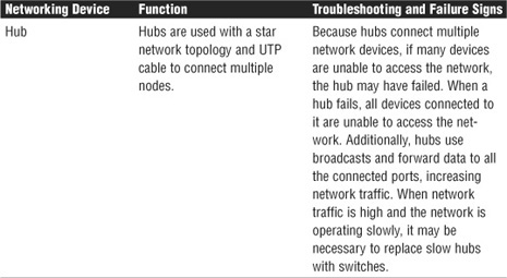
For more information on network hardware devices and their functions, refer to Chapter 3, “Networking Components and Devices.”
Configuring and Troubleshooting Client Connectivity
Connecting clients to an existing network is a common task for network administrators. Connecting a client system involves several steps, including establishing the physical connection, defining network protocols, assigning permissions, and accessing server services and resources. This section explores the requirements for connecting a client PC to a network.
Troubleshooting Client Physical Connections
Establishing physical connectivity requires configuring the client network card and connecting the system to the network medium. The first step is to select the network card. Today, selecting a NIC is simple, although you need to consider a few factors:
![]() Bus compatibility: Some older systems have only Industry Standard Architecture (ISA) slots, but most modern systems have either Peripheral Component Interconnect (PCI) slots or both PCI and ISA slots. Either way, verify that an expansion slot of the correct type is available.
Bus compatibility: Some older systems have only Industry Standard Architecture (ISA) slots, but most modern systems have either Peripheral Component Interconnect (PCI) slots or both PCI and ISA slots. Either way, verify that an expansion slot of the correct type is available.
![]() Type of network: As mentioned in the discussion of NICs in Chapter 3, unless you are using a networking system other than Ethernet, you should not need to specify another type of NIC.
Type of network: As mentioned in the discussion of NICs in Chapter 3, unless you are using a networking system other than Ethernet, you should not need to specify another type of NIC.
![]() Media compatibility: Today, although most NICs have UTP-based connections, some exceptions exist. Some older networks might require coaxial connections, newer networks might require a NIC that can support fiber-optic cable, and still other networks might use wireless NICs.
Media compatibility: Today, although most NICs have UTP-based connections, some exceptions exist. Some older networks might require coaxial connections, newer networks might require a NIC that can support fiber-optic cable, and still other networks might use wireless NICs.
Besides these criteria, which dictate to a certain extent which cards you can use, the choice also depends on manufacturer, cost, and requirements. The NIC might come preinstalled in the system or, as in an increasing number of cases, the network interface might be built into the system board. In either of these situations, you do not have to install a NIC.
Connecting to Network Media
With the NIC chosen and functioning, the next step is to connect the PC to the network medium. This can be simple or complicated, depending on the type of network you are using. The following are some of the factors to consider when connecting a new system to an existing network:
![]() Connecting to a coaxial network: The biggest consideration when connecting to a coaxial network is that it might be necessary to break the coaxial segment to insert a British Naval Connector (BNC) T-connector to physically connect the PC. Recall from Chapter 1, “Introduction to Networking,” that breaking a coaxial cable segment prevents any device connected to it from working. So if you are adding a computer to a coaxial segment and you need to add a length of cable and a connector, you need to either arrange with network users for a few minutes when the network will be unavailable, or add the cable and connector before or after working hours. The good news is that you can leave spare BNC T-connectors in the coaxial cable segment as a precaution. That way, you can add a system to the coaxial segment without affecting users other than the one whose system you are connecting.
Connecting to a coaxial network: The biggest consideration when connecting to a coaxial network is that it might be necessary to break the coaxial segment to insert a British Naval Connector (BNC) T-connector to physically connect the PC. Recall from Chapter 1, “Introduction to Networking,” that breaking a coaxial cable segment prevents any device connected to it from working. So if you are adding a computer to a coaxial segment and you need to add a length of cable and a connector, you need to either arrange with network users for a few minutes when the network will be unavailable, or add the cable and connector before or after working hours. The good news is that you can leave spare BNC T-connectors in the coaxial cable segment as a precaution. That way, you can add a system to the coaxial segment without affecting users other than the one whose system you are connecting.
![]() Connecting to a twisted-pair network: Twisted pair is the easiest of all the network types to connect to. All you need to connect is a cable (called a patch cable) that connects the system to a hub or switch. In environments that use a structured cable system, the cable can be connected to a wall jack or a jack in a floor box. In a less structured environment, the cable can be run directly between the system and the hub or switch.
Connecting to a twisted-pair network: Twisted pair is the easiest of all the network types to connect to. All you need to connect is a cable (called a patch cable) that connects the system to a hub or switch. In environments that use a structured cable system, the cable can be connected to a wall jack or a jack in a floor box. In a less structured environment, the cable can be run directly between the system and the hub or switch.
With the network card installed and the client system connected to the medium, the client is physically attached to the network. The next step is to configure the network protocols.
Configuring Client Systems for TCP/IP
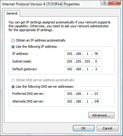
Configuring a client for TCP/IP can be relatively complex, or it can be simple. Any complexity involved is related to the possible need to configure TCP/IP manually. The simplicity is related to the fact that TCP/IP configuration can occur automatically via Dynamic Host Configuration Protocol (DHCP) or through Automatic Private IP Addressing (APIPA). This section looks at some of the basic information required to make a system function on a network using TCP/IP. At the least, a system needs an IP address and a subnet mask. The default gateway, DNS server, and WINS server are all optional, but network functionality is limited without them. The following list briefly explains the IP-related settings used to connect to a TCP/IP network:
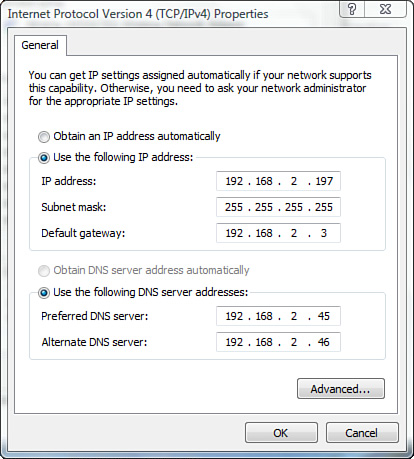
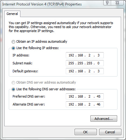
![]() IP address: Each system must be assigned a unique IP address so that it can communicate on the network. Clients on a LAN will have a private IP address and matching subnet mask. Table 11.2 shows the private IP ranges. If a system has the wrong IP or subnet mask, it cannot communicate on the network. If the client system has an IP address in the 169.254.0.0 range, the system is not connected to a DHCP server and is not getting on the network. Refer to Chapter 5, “TCP/IP Routing and Addressing,” for information on APIPA and automatic IPv4 assignments.
IP address: Each system must be assigned a unique IP address so that it can communicate on the network. Clients on a LAN will have a private IP address and matching subnet mask. Table 11.2 shows the private IP ranges. If a system has the wrong IP or subnet mask, it cannot communicate on the network. If the client system has an IP address in the 169.254.0.0 range, the system is not connected to a DHCP server and is not getting on the network. Refer to Chapter 5, “TCP/IP Routing and Addressing,” for information on APIPA and automatic IPv4 assignments.
Table 11.2 Private Address Ranges
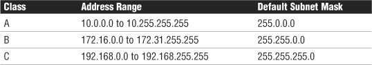
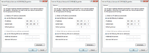
![]() Subnet mask: The subnet mask allows the system to determine what portion of the IP address represents the network address and what portion represents the node address. Table 11.2 shows the default subnet mask associated with each private IP range. To be part of the network, each client system needs the correct subnet mask, and the subnet mask must use the matching one used with the rest of the network. Figure 11.1 shows a correct IP configuration and two incorrect IP configurations on a Windows Vista system. Using Table 11.2, can you tell which is the correct configuration?
Subnet mask: The subnet mask allows the system to determine what portion of the IP address represents the network address and what portion represents the node address. Table 11.2 shows the default subnet mask associated with each private IP range. To be part of the network, each client system needs the correct subnet mask, and the subnet mask must use the matching one used with the rest of the network. Figure 11.1 shows a correct IP configuration and two incorrect IP configurations on a Windows Vista system. Using Table 11.2, can you tell which is the correct configuration?
FIGURE 11.1 One correct and two incorrect IP client configurations.
![]() Default gateway: The default gateway allows internal systems to communicate with systems on a remote network. In home use, the gateway would likely be the DSL or cable modem, which acts as a router. In a business environment the gateway is the device that routes traffic from the workstation to the outside network. This network device has an IP address assigned to it, and the client configuration must use this address as the default gateway. If it doesn’t, the system cannot be routed outside the local network.
Default gateway: The default gateway allows internal systems to communicate with systems on a remote network. In home use, the gateway would likely be the DSL or cable modem, which acts as a router. In a business environment the gateway is the device that routes traffic from the workstation to the outside network. This network device has an IP address assigned to it, and the client configuration must use this address as the default gateway. If it doesn’t, the system cannot be routed outside the local network.
![]() DNS server addresses: DNS servers allow dynamic hostname resolution to be performed. It is common practice to have two DNS server addresses defined so that if one server becomes unavailable, the other can be used. The client system must be configured with the IP address of the local DNS server. If a client system has the wrong DNS address listed, hostname resolution is impossible.
DNS server addresses: DNS servers allow dynamic hostname resolution to be performed. It is common practice to have two DNS server addresses defined so that if one server becomes unavailable, the other can be used. The client system must be configured with the IP address of the local DNS server. If a client system has the wrong DNS address listed, hostname resolution is impossible.
Exactly how this information is entered on the client depends on the operating system being configured. For example, Figure 11.2 shows the Internet Protocol Version 4 (TCP/IPv4) Properties dialog box on a Windows Vista system. As you can see, this system is fully configured for operation on a private network.
FIGURE 11.2 The Internet Protocol Version 4 (TCP/IPv4) Properties dialog box on a Windows Vista system.
Setting Port Speeds and Duplex
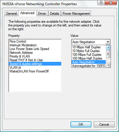
When configuring a client for the network, you need to be aware of two more settings—port speed and duplex settings. These are adjusted in Windows in the Network Properties area. Figure 11.3 shows the port speed and duplex settings of a Windows Vista system.
As shown in Figure 11.3, you have several choices for port speed and duplex settings. You can choose Auto Negotiation to detect the setting that the network uses. You also can choose one of the other settings to match the network configuration, such as 100Mbps Half Duplex. If you are working with a client system that is unable to log on to a network, you might need to ensure that the duplex setting and port speeds are set correctly for the network.
FIGURE 11.3 The port speed and duplex settings on a Windows Vista system.
Troubleshooting an Incorrect VLAN
As mentioned in Chapter 1, VLANs provide a method of segmenting and organizing the network. Computer systems can be located anywhere on the network but communicate as if they are on the same segment. For example, networks with VLANs can be segmented according to an organization’s departments, such as sales, finance, and secretaries, or can be segmented according to usage, security permissions, and more.
Being able to segment the network offers some clear advantages. It provides increased security, because devices can communicate only with other systems in the VLAN. Users can see only the systems in their VLAN segment. This can help control broadcast traffic and makes it easier to move end systems around the network.
Problems can arise when users are moved or otherwise connected to the wrong VLAN. Administrators have to ensure that the user system is plugged into the correct VLAN port. For example, suppose a network is using port-based VLANs to assign ports 1 through 8 to marketing, ports 9 through 18 to sales, and so on. Plugging a sales client into port 6 would make that sales client part of the marketing network. This sounds simple, but if the documentation is not up to date and you are walking into a new network, this can be tricky to identify.
One of the keys to preventing VLAN assignment errors is to clearly document the VLAN arrangement. If systems are moved, it is important to know how to reconnect them and forward them to the correct VLAN port.
Another consideration to keep in mind is that membership to a VLAN can be assigned both statically and dynamically. In static VLAN assignment, the switch ports are assigned to a specific VLAN. New systems that are added are assigned to the VLAN that is associated with that particular port. For example, if you plug a new system into port 8, the user becomes part of the administrator’s network. So you must ensure that you have the right port assigned to users.
Dynamic VLAN assignment requires specific software to control VLAN distribution. Using a VLAN server, administrators can dynamically assign VLAN membership based on criteria such as MAC address or a username/password combination. As a system tries to access the network, it queries the VLAN server database to ask for VLAN membership information. The server responds and logs the system onto the appropriate VLAN network. When configured correctly, dynamic assignment reduces the human error associated with static VLAN assignment.
Topology Errors
Each physical network topology requires its own troubleshooting strategies and methods. When you’re troubleshooting a network, it is important to know which topology is used, because this can greatly impact the procedures used to resolve any problems. This section describes each of the respective physical network topologies and some common troubleshooting strategies.
Star Topology
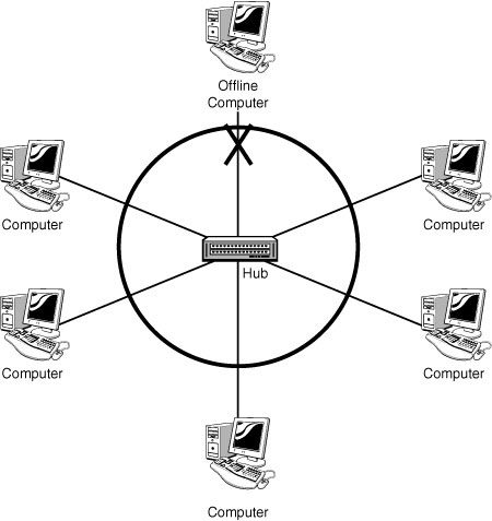
The most common topology used today is the star topology. It uses a central connection point such as a hub to connect all the devices on the network. Each device on the network uses its own length of cable, thus allowing devices to be added to or removed from the network without disrupting current network users. When troubleshooting a physical star network, consider the following:
![]() The central device, a hub or switch, provides a single point of failure. A loss of connectivity for several users might involve a faulty hub. Try placing the cables in a known working hub to confirm. You could even recycle the power to the hub or switch to see if that simple fix solves the problem.
The central device, a hub or switch, provides a single point of failure. A loss of connectivity for several users might involve a faulty hub. Try placing the cables in a known working hub to confirm. You could even recycle the power to the hub or switch to see if that simple fix solves the problem.
![]() Hubs and switches provide light-emitting diodes (LEDs) that provide information on the port status. For instance, by using the LEDs, you can determine whether there is a jabbering network card, whether there is a proper connection to the network device, and whether there are too many collisions on the network.
Hubs and switches provide light-emitting diodes (LEDs) that provide information on the port status. For instance, by using the LEDs, you can determine whether there is a jabbering network card, whether there is a proper connection to the network device, and whether there are too many collisions on the network.
![]() Each device, printer, or computer connects to a central device using its own length of cable. When troubleshooting a connectivity error in a star network, you might need to verify that the cable works. You can do this by swapping the cable with a known working one or by using a cable tester.
Each device, printer, or computer connects to a central device using its own length of cable. When troubleshooting a connectivity error in a star network, you might need to verify that the cable works. You can do this by swapping the cable with a known working one or by using a cable tester.
![]() Ensure that the patch cables and cables have the correct specifications and that the correct cable is being used, such as a straight-through or crossover cable.
Ensure that the patch cables and cables have the correct specifications and that the correct cable is being used, such as a straight-through or crossover cable.
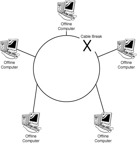
Figure 11.4 shows how a single cable break would affect only a single client system on the network.
FIGURE 11.4 Identifying cable breaks in a star network.
Ring Topology
Although it’s not as commonly used as it once was, you might find yourself troubleshooting a ring network. Most ring networks are logical rings, meaning that each computer is logically connected to the others. The ring’s function is performed by a central hub, not an actual physical ring topology. A physical ring topology is rare, but a Fiber Distributed Data Interface (FDDI) network often is configured in a physical ring topology. The FDDI actually uses two rings, a primary and a secondary. This creates fault tolerance: if one ring fails, data can still travel through the network using the other ring.
A logical ring topology uses a central connecting device, as with a star network, called a multistation access unit (MSAU). When troubleshooting either a logical or physical ring topology, consider the following:
![]() A physical ring topology uses a single length of cable, interconnecting all computers and forming a loop. If there is a break in the cable, all systems on the network are unable to access the network.
A physical ring topology uses a single length of cable, interconnecting all computers and forming a loop. If there is a break in the cable, all systems on the network are unable to access the network.
![]() The MSAU on a logical ring topology represents a single point of failure. If all devices are unable to access the network, the MSAU might be faulty.
The MSAU on a logical ring topology represents a single point of failure. If all devices are unable to access the network, the MSAU might be faulty.
![]() Verify that the cabling and connectors have the correct specifications.
Verify that the cabling and connectors have the correct specifications.
![]() All NICs on the ring network must operate at the same speed.
All NICs on the ring network must operate at the same speed.
![]() When connecting MSAUs in a ring network, ensure that the ring in and ring out configuration is properly set.
When connecting MSAUs in a ring network, ensure that the ring in and ring out configuration is properly set.
Figure 11.5 shows how a single cable break would affect other client systems on a physical ring network.
FIGURE 11.5 Identifying cable breaks in a physical ring network.
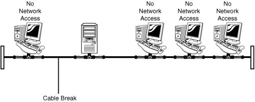
Bus Network Errors
Although the bus topology is rarely implemented anymore, enough of them are out there for it to be included in the CompTIA Network+ exam objectives. So even if you do not encounter a bus network in the real world, you will most certainly see one on the exam.
Troubleshooting a bus network can be a difficult and frustrating task. The following are a few hotspots to be aware of when troubleshooting a bus network:
![]() A bus topology must be continuous: A break in the cable at any point renders the entire segment unusable. If the location of the break is not apparent, you can check each length of cable systematically from one end to the other to find the break. Or you can use a tool such as a time domain reflectometer (TDR) to locate the break.
A bus topology must be continuous: A break in the cable at any point renders the entire segment unusable. If the location of the break is not apparent, you can check each length of cable systematically from one end to the other to find the break. Or you can use a tool such as a time domain reflectometer (TDR) to locate the break.
![]() The cable used on a bus network has two distinct physical endpoints. Each of these cable ends requires a terminator: Terminators are used to absorb electronic signals so that they are not reflected on the medium, compromising data integrity. A failed or missing terminator would render the entire network segment unusable.
The cable used on a bus network has two distinct physical endpoints. Each of these cable ends requires a terminator: Terminators are used to absorb electronic signals so that they are not reflected on the medium, compromising data integrity. A failed or missing terminator would render the entire network segment unusable.
![]() The addition, removal, or failure of a device on the network might prevent the entire network from functioning: The coaxial cable used in a bus network can be damaged very easily. Moving cables in order to add or remove devices can cause cable problems. The T-connectors used on bus networks allow devices to be added and removed without necessarily affecting the network, but you must be careful when doing this.
The addition, removal, or failure of a device on the network might prevent the entire network from functioning: The coaxial cable used in a bus network can be damaged very easily. Moving cables in order to add or remove devices can cause cable problems. The T-connectors used on bus networks allow devices to be added and removed without necessarily affecting the network, but you must be careful when doing this.
![]() One end of the bus network should be grounded: Intermittent problems or a high occurrence of errors can indicate poor or insufficient grounding.
One end of the bus network should be grounded: Intermittent problems or a high occurrence of errors can indicate poor or insufficient grounding.
Figure 11.6 shows how a single cable break affects other client systems on a bus network.
FIGURE 11.6 Identifying cable breaks in a bus network.
Mesh Network Errors
A mesh topology offers high redundancy by providing several paths for data to reach its destination. In a true mesh network, each device on the network is connected to every other device, so if one cable fails, another can provide an alternative data path. Although a mesh topology is resilient to failure, the number of connections involved can make a mesh network somewhat tricky to troubleshoot.
When troubleshooting a mesh network, consider the following points:
![]() A mesh topology interconnects all devices on the network, offering the highest level of redundancy of all the topologies. In a pure mesh environment, all devices are directly connected to all other devices. In a hybrid mesh environment, some devices are connected only to certain others in the topology.
A mesh topology interconnects all devices on the network, offering the highest level of redundancy of all the topologies. In a pure mesh environment, all devices are directly connected to all other devices. In a hybrid mesh environment, some devices are connected only to certain others in the topology.
![]() Although a mesh topology can accommodate failed links, mechanisms should still be in place so that failed links are detected and reported.
Although a mesh topology can accommodate failed links, mechanisms should still be in place so that failed links are detected and reported.
![]() Design and implementation of a true mesh network can be complex and often requires specialized hardware devices.
Design and implementation of a true mesh network can be complex and often requires specialized hardware devices.
Mesh networks are so rare that it’s unlikely you will be faced with troubleshooting one, but there will likely be questions on the Network+ Exam that focus on mesh networks.
Issue Escalation
Earlier in this chapter we discussed when escalation procedures may be necessary. The CompTIA Network+ objectives list certain scenarios in which escalation might be necessary. Not all of these issues always require escalation, however. In fact, an administrator with an Internet connection and a little determination can sometimes track them down. Nevertheless, we will quickly discuss each of the issues listed in the CompTIA objectives:
![]() Switching loop: An Ethernet network can have only a single active path between devices on a network. When multiple active paths are available, switching loops can occur. Switching loops are simply the result of having more than one path between two switches in a network. Spanning Tree Protocol (STP) is designed to prevent these loops from occurring. If the packet in the loop is a broadcast message, the loop can create a full broadcast storm (as discussed at the end of this list). Switching loops occur at the data-link layer (Layer 2) of the OSI model.
Switching loop: An Ethernet network can have only a single active path between devices on a network. When multiple active paths are available, switching loops can occur. Switching loops are simply the result of having more than one path between two switches in a network. Spanning Tree Protocol (STP) is designed to prevent these loops from occurring. If the packet in the loop is a broadcast message, the loop can create a full broadcast storm (as discussed at the end of this list). Switching loops occur at the data-link layer (Layer 2) of the OSI model.
![]() Routing loop: As the name suggests, a routing loop occurs when data packets continue to be routed in an endless circle. In proper operation, a router forwards packets according to the information in the routing table. If the routing table is correct, the packet takes the optimal path from the source to the destination. It is not common, but if the information in the routing table is incorrect through a manual misconfiguration or faulty route detection, routing loops can form. A routing loop is a path through the internetwork for a network ID that loops back onto itself. Routing loops are detectable because they can quickly bog down a network, and the destination system does not receive some packets.
Routing loop: As the name suggests, a routing loop occurs when data packets continue to be routed in an endless circle. In proper operation, a router forwards packets according to the information in the routing table. If the routing table is correct, the packet takes the optimal path from the source to the destination. It is not common, but if the information in the routing table is incorrect through a manual misconfiguration or faulty route detection, routing loops can form. A routing loop is a path through the internetwork for a network ID that loops back onto itself. Routing loops are detectable because they can quickly bog down a network, and the destination system does not receive some packets.
![]() Route problems: Route problems typically occur when routing tables contain information that does not reflect the correct topology of the internetwork. Out of date or incorrect routing tables mean that packets cannot be correctly routed through the network, and route problems occur. Verify the routing table to ensure that it is correct. Sometimes static routes are entered and cause problems when the network topology is changed.
Route problems: Route problems typically occur when routing tables contain information that does not reflect the correct topology of the internetwork. Out of date or incorrect routing tables mean that packets cannot be correctly routed through the network, and route problems occur. Verify the routing table to ensure that it is correct. Sometimes static routes are entered and cause problems when the network topology is changed.
![]() Proxy ARP: As mentioned in Chapter 8, “Network Performance Optimization,” ARP is used to resolve IP addresses to MAC addresses. This is important because on a network, devices find each other using the IP address, but communication between devices requires the MAC address. In a proxy ARP configuration, one system or network device answers ARP requests for another system. It is proxy ARP because one network system is proxying for another’s ARP communications.
Proxy ARP: As mentioned in Chapter 8, “Network Performance Optimization,” ARP is used to resolve IP addresses to MAC addresses. This is important because on a network, devices find each other using the IP address, but communication between devices requires the MAC address. In a proxy ARP configuration, one system or network device answers ARP requests for another system. It is proxy ARP because one network system is proxying for another’s ARP communications.
![]() Broadcast storms: Recall from Chapter 5, that a broadcast address is an IP address that you can use to target all systems on a subnet or network instead of single hosts. In other words, a broadcast message goes to everyone on the network. A broadcast storm occurs when a network is overwhelmed with constant broadcast or multicast traffic. Broadcast storms can eventually lead to a complete loss of network connectivity as the network is bogged down with the broadcast storm. As with other network problems, you may suspect a broadcast storm when network response times are poor and people are complaining about the slow network. These broadcast storms can be caused by faulty hardware such as a NIC that continually sends data, switching loops, or even faulty applications running on the network. Baselines work well for identifying broadcast storms.
Broadcast storms: Recall from Chapter 5, that a broadcast address is an IP address that you can use to target all systems on a subnet or network instead of single hosts. In other words, a broadcast message goes to everyone on the network. A broadcast storm occurs when a network is overwhelmed with constant broadcast or multicast traffic. Broadcast storms can eventually lead to a complete loss of network connectivity as the network is bogged down with the broadcast storm. As with other network problems, you may suspect a broadcast storm when network response times are poor and people are complaining about the slow network. These broadcast storms can be caused by faulty hardware such as a NIC that continually sends data, switching loops, or even faulty applications running on the network. Baselines work well for identifying broadcast storms.
Review and Test Yourself
The following sections provide you with the opportunity to review what you’ve learned in this chapter and to test yourself.
The Facts
For the exam, don’t forget these important concepts:
![]() When presented with a troubleshooting scenario, consider the following procedure:
When presented with a troubleshooting scenario, consider the following procedure:
![]() Information gathering: identify symptoms and problems.
Information gathering: identify symptoms and problems.
![]() Identify the affected areas of the network.
Identify the affected areas of the network.
![]() Determine if anything has changed.
Determine if anything has changed.
![]() Establish the most probable cause.
Establish the most probable cause.
![]() Determine if escalation is necessary.
Determine if escalation is necessary.
![]() Create an action plan and solution identifying potential effects.
Create an action plan and solution identifying potential effects.
![]() Implement and test the solution.
Implement and test the solution.
![]() Identify the results and effects of the solution.
Identify the results and effects of the solution.
![]() Document the solution and the entire process.
Document the solution and the entire process.
![]() The central device, a hub or switch, provides a single point of failure.
The central device, a hub or switch, provides a single point of failure.
![]() Hubs and switches have LEDs that provide information about the port status and device power status.
Hubs and switches have LEDs that provide information about the port status and device power status.
![]() A physical ring topology uses a single length of cable interconnecting all computers and forming a loop. If there is a break in the cable, none of the systems on the network can access the network.
A physical ring topology uses a single length of cable interconnecting all computers and forming a loop. If there is a break in the cable, none of the systems on the network can access the network.
![]() The MSAU on a logical ring topology represents a single point of failure. If all devices are unable to access the network, the MSAU might be faulty.
The MSAU on a logical ring topology represents a single point of failure. If all devices are unable to access the network, the MSAU might be faulty.
![]() Verify that the cabling and connectors meet the correct specifications.
Verify that the cabling and connectors meet the correct specifications.
![]() A bus topology must be continuous and correctly terminated at both ends. A break in the cable at any point will render the entire segment unusable.
A bus topology must be continuous and correctly terminated at both ends. A break in the cable at any point will render the entire segment unusable.
![]() The cable used on a bus network has two distinct physical endpoints.
The cable used on a bus network has two distinct physical endpoints.
![]() The addition, removal, or failure of a device on the bus network might prevent the entire network from functioning.
The addition, removal, or failure of a device on the bus network might prevent the entire network from functioning.
Key Terms
![]() Topology
Topology
![]() Bus
Bus
![]() Star
Star
![]() Ring
Ring
![]() Mesh
Mesh
![]() Wireless
Wireless
![]() Protocol
Protocol
![]() Authentication
Authentication
![]() Medium
Medium
![]() Interference
Interference
![]() Attenuation
Attenuation
![]() EMI
EMI
![]() Segment
Segment
![]() Hub
Hub
![]() Switch
Switch
![]() MSAU
MSAU
![]() Termination
Termination
Exam Prep Questions
1. Consider the following figure. Which of the following statements is true?
![]() A. The system cannot access the local network.
A. The system cannot access the local network.
![]() B. The system is configured correctly and can access network resources.
B. The system is configured correctly and can access network resources.
![]() C. The subnet mask should be 255.255.0.0 to access network resources.
C. The subnet mask should be 255.255.0.0 to access network resources.
![]() D. The IP address 192.168.2.197 is not a valid IP address.
D. The IP address 192.168.2.197 is not a valid IP address.
2. Consider the following figure. Which of the following statements is true?
![]() A. The system cannot access the local network.
A. The system cannot access the local network.
![]() B. The system cannot access remote networks.
B. The system cannot access remote networks.
![]() C. The system cannot have hostname resolution.
C. The system cannot have hostname resolution.
![]() D. The system has the wrong subnet mask.
D. The system has the wrong subnet mask.
3. Which of the following best describes the function of the default gateway?
![]() A. It converts hostnames to IP addresses.
A. It converts hostnames to IP addresses.
![]() B. It converts IP addresses to hostnames.
B. It converts IP addresses to hostnames.
![]() C. It allows systems to communicate with systems on a remote network.
C. It allows systems to communicate with systems on a remote network.
![]() D. It allows systems to communicate with routers.
D. It allows systems to communicate with routers.
4. Which of the following bits of IP information are mandatory to join the network? (Choose two.)
![]() A. Subnet mask
A. Subnet mask
![]() B. IP address
B. IP address
![]() C. DNS address
C. DNS address
![]() D. Default gateway
D. Default gateway
5. You are wiring a new network. Due to space limitations, you need to run several cables close to each other. After the setup, you find that the signals from each cable are overlapping. Which term describes what is happening?
![]() A. Attenuation
A. Attenuation
![]() B. Crosstalk
B. Crosstalk
![]() C. Near crosstalk
C. Near crosstalk
![]() D. EMI
D. EMI
6. Which of the following should you consider when troubleshooting wiring problems? (Choose the three best answers.)
![]() A. The distance between devices
A. The distance between devices
![]() B. Interference
B. Interference
![]() C. Atmospheric conditions
C. Atmospheric conditions
![]() D. Connectors
D. Connectors
7. You get numerous calls from users who are unable to access an application. Upon investigation, you find that the application has crashed. You restart the application, and it appears to run okay. What is the next step in the troubleshooting process?
![]() A. Email the users and let them know that they can use the application again.
A. Email the users and let them know that they can use the application again.
![]() B. Test the application to ensure that it is operating correctly.
B. Test the application to ensure that it is operating correctly.
![]() C. Document the problem and the solution.
C. Document the problem and the solution.
![]() D. Reload the application executables from the CD, and restart it.
D. Reload the application executables from the CD, and restart it.
8. A user tells you that she is having a problem accessing her email. What is the first step in the troubleshooting process?
![]() A. Document the problem.
A. Document the problem.
![]() B. Make sure that the user’s email address is valid.
B. Make sure that the user’s email address is valid.
![]() C. Discuss the problem with the user.
C. Discuss the problem with the user.
![]() D. Visit the user’s desk to reload the email client software.
D. Visit the user’s desk to reload the email client software.
9. You have successfully fixed a problem with a server and have tested the application and let the users back onto the system. What is the next step in the troubleshooting process?
![]() A. Document the problem.
A. Document the problem.
![]() B. Restart the server.
B. Restart the server.
![]() C. Document the problem and the solution.
C. Document the problem and the solution.
![]() D. Clear the error logs of any reference to the problem.
D. Clear the error logs of any reference to the problem.
10. You are called in to troubleshoot a problem with the NIC on a server that has been running well for some time. The server reports a resource conflict. What is the next step in the troubleshooting process?
![]() A. Change the NIC.
A. Change the NIC.
![]() B. Consult the documentation to determine whether any changes have occurred to the server configuration.
B. Consult the documentation to determine whether any changes have occurred to the server configuration.
![]() C. Download and install the latest drivers for the NIC.
C. Download and install the latest drivers for the NIC.
![]() D. Reload the protocol drivers for the NIC, and set them to use a different set of resources.
D. Reload the protocol drivers for the NIC, and set them to use a different set of resources.
Answers to Exam Prep Questions
1. A. The 192.168.x.x private address range corresponds with the subnet mask of 255.255.255.0; therefore, the subnet mask shown is incorrect. Because of this wrong configuration, the system would be unable to access the network. Answer D is incorrect because 192.168.2.197 is a valid IP address.
2. B. The IP addresses of the client system and the default gateway are the same. This error probably occurred when the IP address information was input. In this configuration, the client system would likely be able to access the local network and resources but not remote networks, because the gateway address to remote networks is wrong. The DNS, IP, and subnet mask settings are correct.
3. C. The default gateway allows the system to communicate with systems on a remote network, without the need for explicit routes to be defined. The default gateway can be assigned automatically using a DHCP server or can be input manually.
4. A, B. Configuring a client requires at least the IP address and a subnet mask. The default gateway, DNS server, and WINS server are all optional, but network functionality is limited without them.
5. B. Crosstalk can occur when the signal from one cable overlaps with the signal from another. This can sometimes happen when cables are run too close together. The remedy is to run the cables farther apart and use quality shielded cable.
6. A, B, D. When you’re troubleshooting a wiring problem, consider the distance between devices, interference such as crosstalk and EMI, and the connection points. Answer C is incorrect because bound media (that is, cables) are unaffected by atmospheric conditions.
7. B. After you have fixed a problem, you should test it fully to ensure that the network is operating correctly before you allow users to log back on. The steps described in answers A and C are valid, but only after the application has been tested. Answer D is incorrect because you would reload the executable only as part of a systematic troubleshooting process. Because the application loads, it is unlikely that the executable has become corrupted.
8. C. Not enough information is provided for you to come up with a solution. In this case, the next troubleshooting step would be to talk to the user and gather more information about exactly what the problem is. All the other answers are valid troubleshooting steps, but only after the information gathering has been completed.
9. C. After you have fixed a problem, tested the fix, and let users back on to the system, you should create detailed documentation that describes the problem and the solution. Answer A is incorrect because you must document both the problem and the solution. It is not necessary to restart the server, so Answer B is incorrect. Answer D would be performed only after the system’s documentation has been created.
10. B. In a server that has been operating correctly, a resource conflict could indicate that a device has failed and is causing the conflict. More likely, a change has been made to the server, and that change has created a conflict. Although all the other answers are valid troubleshooting steps, it is most likely that a change has been made to the configuration.
Need to Know More?
Mike Harwood. Network+ Exam Prep, 3rd Edition. Que Publishing, 2009. Larry Peterson and Bruce Davie. Computer Networks: A Systems Approach, Fourth Edition (The Morgan Kaufmann Series in Networking). Morgan Kaufmann, 2007.