Chapter Two. Cabling, Connectors, and Ethernet Standards
Objectives
2.1 Categorize standard cable types and their properties
![]() Types:
Types:
![]() CAT3, CAT5, CAT5e, CAT6
CAT3, CAT5, CAT5e, CAT6
![]() STP, UTP
STP, UTP
![]() Multimode fiber, single-mode fiber
Multimode fiber, single-mode fiber
![]() Coaxial
Coaxial
![]() RG-59
RG-59
![]() RG-6
RG-6
![]() Serial
Serial
![]() Plenum vs. Non-plenum
Plenum vs. Non-plenum
![]() Properties:
Properties:
![]() Transmission speeds
Transmission speeds
![]() Distance
Distance
![]() Duplex
Duplex
![]() Noise immunity (security, EMI)
Noise immunity (security, EMI)
![]() Frequency
Frequency
2.2 Identify common connector types
![]() RJ-11
RJ-11
![]() RJ-45
RJ-45
![]() BNC
BNC
![]() SC
SC
![]() ST
ST
![]() LC
LC
![]() RS-232
RS-232
![]() RG-59
RG-59
![]() RG-6
RG-6
2.4 Given a scenario, differentiate and implement appropriate wiring standards
![]() 568A
568A
![]() 568B
568B
![]() Straight vs. cross-over
Straight vs. cross-over
![]() Rollover
Rollover
![]() Loopback
Loopback
2.6 Categorize LAN technology types and properties
![]() Types:
Types:
![]() Ethernet
Ethernet
![]() 10BaseT
10BaseT
![]() 100BaseTX
100BaseTX
![]() 100BaseFX
100BaseFX
![]() 1000BaseT
1000BaseT
![]() 1000BaseX
1000BaseX
![]() 10GBaseSR
10GBaseSR
![]() 10GBaseLR
10GBaseLR
![]() 10GBaseER
10GBaseER
![]() 10GBaseSW
10GBaseSW
![]() 10GBaseLW
10GBaseLW
![]() 10GBaseEW
10GBaseEW
![]() 10GBaseT
10GBaseT
![]() Properties:
Properties:
![]() CSMA/CD
CSMA/CD
![]() Broadcast
Broadcast
![]() Collision
Collision
![]() Bonding
Bonding
![]() Speed
Speed
![]() Distance
Distance
2.8 Install components of wiring distribution
![]() Vertical and horizontal cross connects
Vertical and horizontal cross connects
![]() Patch panels
Patch panels
![]() 66 block
66 block
![]() MDFs
MDFs
![]() IDFs
IDFs
![]() 25 pair
25 pair
![]() 100 pair
100 pair
![]() 110 block
110 block
![]() Demarc
Demarc
![]() Demarc extension
Demarc extension
![]() Smart jack
Smart jack
![]() Verify wiring installation
Verify wiring installation
![]() Verify wiring termination
Verify wiring termination
What You Need to Know
![]() Identify common media considerations.
Identify common media considerations.
![]() Understand the relationship between media and bandwidth.
Understand the relationship between media and bandwidth.
![]() Identify the two signaling methods used on networks.
Identify the two signaling methods used on networks.
![]() Understand the three media dialog methods.
Understand the three media dialog methods.
![]() Identify the characteristics of IEEE standards, including 802.3, 802.3u, 802.3z, and 802.3ae.
Identify the characteristics of IEEE standards, including 802.3, 802.3u, 802.3z, and 802.3ae.
![]() Identify the commonly implemented network media.
Identify the commonly implemented network media.
![]() Identify the various connectors used with network media.
Identify the various connectors used with network media.
Introduction
When it comes to working with an existing network or implementing a new one, you need to be able to identify the characteristics of network media and their associated cabling. This chapter focuses on the media and connectors used in today’s networks and how they fit into wiring closets.
In addition to media and connectors, this chapter identifies the characteristics of the IEEE 802.3 standard and its variants.
General Media Considerations
In addition to identifying the characteristics of network media and their associated cabling, the Network+ exam requires knowledge of some general terms and concepts that are associated with network media. Before looking at the individual media types, it is a good idea to first have an understanding of some general media considerations.
Broadband Versus Baseband
Networks employ two types of signaling methods:
![]() Baseband transmissions: Use digital signaling over a single wire. Communication on baseband transmissions is bidirectional, allowing signals to be sent and received, but not at the same time. To send multiple signals on a single cable, baseband uses something called Time Division Multiplexing (TDM). TDM divides a single channel into time slots.
Baseband transmissions: Use digital signaling over a single wire. Communication on baseband transmissions is bidirectional, allowing signals to be sent and received, but not at the same time. To send multiple signals on a single cable, baseband uses something called Time Division Multiplexing (TDM). TDM divides a single channel into time slots.
![]() Broadband transmissions: In terms of LAN network standards, broadband transmissions use analog transmissions. For broadband transmissions to be sent and received, the medium must be split into two channels. Multiple channels are created using Frequency Division Multiplexing (FDM).
Broadband transmissions: In terms of LAN network standards, broadband transmissions use analog transmissions. For broadband transmissions to be sent and received, the medium must be split into two channels. Multiple channels are created using Frequency Division Multiplexing (FDM).
Simplex, Half Duplex, and Full Duplex
Simplex, half duplex, and full duplex are referred to as dialog modes, and they determine the direction in which data can flow through the network media:
![]() Simplex mode allows for one-way communication of data through the network, with the full bandwidth of the cable being used for the transmitting signal. One-way communication is of little use on LANs, making it unusual at best for network implementations.
Simplex mode allows for one-way communication of data through the network, with the full bandwidth of the cable being used for the transmitting signal. One-way communication is of little use on LANs, making it unusual at best for network implementations.
![]() Far more common is half-duplex mode, which accommodates transmitting and receiving on the network, but not at the same time. Many networks are configured for half-duplex communication.
Far more common is half-duplex mode, which accommodates transmitting and receiving on the network, but not at the same time. Many networks are configured for half-duplex communication.
![]() The preferred dialog mode for network communication is full-duplex mode. To use full duplex, both the network card and the hub or switch must support full duplexing. Devices configured for full duplexing can transmit and receive simultaneously. This means that 100Mbps network cards theoretically can transmit at 200Mbps using full-duplex mode.
The preferred dialog mode for network communication is full-duplex mode. To use full duplex, both the network card and the hub or switch must support full duplexing. Devices configured for full duplexing can transmit and receive simultaneously. This means that 100Mbps network cards theoretically can transmit at 200Mbps using full-duplex mode.
Media Interference
Depending on where network cabling (commonly called media) is installed, interference can be a major consideration. Two types of media interference can adversely affect data transmissions over network media: electromagnetic interference (EMI) and crosstalk.
EMI is a problem when cables are installed near electrical devices, such as air conditioners or fluorescent light fixtures. If a network medium is placed close enough to such a device, the signal within the cable might become corrupt. Network media vary in their resistance to the effects of EMI. Standard unshielded twisted pair (UTP) cable is susceptible to EMI, whereas fiber cable, with its light transmissions, is resistant to EMI. When deciding on a particular medium, consider where it will run and the impact EMI can have on the installation.
A second type of interference is crosstalk. Crosstalk refers to how the data signals on two separate media interfere with each other. The result is that the signal on both cables can become corrupt. As with EMI, media varies in its resistance to crosstalk, with fiber-optic cable being the most resistant.
Attenuation
Attenuation refers to the weakening of data signals as they travel through a medium. Network media vary in their resistance to attenuation. Coaxial cable generally is more resistant than UTP, STP is slightly more resistant than UTP, and fiber-optic cable does not suffer from attenuation at all. That’s not to say that a signal does not weaken as it travels over fiber-optic cable, but the correct term for this weakening is chromatic dispersion rather than attenuation.
It’s important to understand attenuation or chromatic dispersion and the maximum distances specified for network media. Exceeding a medium’s distance without using repeaters can cause hard-to-troubleshoot network problems. A repeater is a network device that amplifies data signals as they pass, allowing them to travel farther. Most attenuation- or chromatic dispersion-related difficulties on a network require using a network analyzer to detect them.
Data Transmission Rates
One of the more important media considerations is the supported data transmission rate or speed. Different media types are rated to certain maximum speeds, but whether they are used to this maximum depends on the networking standard being used and the network devices connected to the network.
Transmission rates normally are measured by the number of data bits that can traverse the medium in a single second. In the early days of data communications, this measurement was expressed in bits per second (bps), but today’s networks are measured in Mbps (megabits per second) and Gbps (gigabits per second).
The different network media vary greatly in the transmission speeds they support. Many of today’s application-intensive networks require more than the 10Mbps offered by the older networking standards. In some cases, even 100Mbps, which is found in many modern LANs, is simply not enough to meet current network needs. For this reason, many organizations deploy 1Gbps networks, and some now even go for 10Gbps implementations.
Network Media
Whatever type of network is used, some type of network medium is needed to carry signals between computers. Two types of media are used in networks: cable-based media, such as twisted pair, and the media types associated with wireless networking, such as radio waves.
In networks using cable-based media, there are three basic choices:
![]() Twisted pair
Twisted pair
![]() Coaxial
Coaxial
![]() Fiber-optic
Fiber-optic
Twisted pair and coaxial cables both use copper wire to conduct the signals electronically; fiber-optic cable uses a glass or plastic conductor and transmits the signals as light.
For many years, coaxial was the cable of choice for most LANs. Today, twisted pair has proven to be far and away the cable medium of choice, thus retiring coaxial to the confines of storage closets. Fiber-optic cable has also seen its popularity rise, but because of cost it has been primarily restricted to use as a network backbone where segment length and higher speeds are needed. That said, fiber is now increasingly common in server room environments as a server-to-switch connection method, and in building-to-building connections in what are called metropolitan area networks (MANs). For more information on MANs, see Chapter 1, “Introduction to Networking.”
The following sections summarize the characteristics of each of these cable types.
Twisted-Pair Cabling
Twisted-pair cabling has been around for a very long time. It was originally created for voice transmissions and has been widely used for telephone communication. Today, in addition to telephone communication, twisted pair is the most widely used medium for networking.
The popularity of twisted pair can be attributed to the fact that it is lighter, more flexible, and easier to install than coaxial or fiber-optic cable. It is also cheaper than other media alternatives and can achieve greater speeds than its coaxial competition. These factors make twisted pair the ideal solution for most network environments.
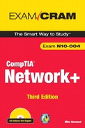
Two main types of twisted-pair cabling are in use today: Unshielded Twisted Pair (UTP) and Shielded Twisted Pair (STP). UTP is significantly more common than STP and is used for most networks. Shielded twisted pair is used in environments in which greater resistance to EMI and attenuation is required. The greater resistance comes at a price, however. The additional shielding, plus the need to ground that shield (which requires special connectors), can significantly add to the cost of a cable installation of STP.
STP provides the extra shielding by using an insulating material that is wrapped around the wires within the cable. This extra protection increases the distances that data signals can travel over STP but also increases the cost of the cabling. Figure 2.1 shows STP and UTP cabling.
FIGURE 2.1 STP and UTP cabling. (Reproduced with permission from Computer Desktop Encyclopedia. 1981–2005. The Computer Language Company, Inc. All rights reserved.)
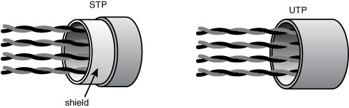
There are several categories of twisted-pair cabling. The early categories are most commonly associated with voice transmissions. The categories are specified by the Electronic Industries Association/Telecommunications Industry Association (EIA/TIA). EIA/TIA is an organization that focuses on developing standards for electronic components, electronic information, telecommunications, and Internet security. These standards are important to ensure uniformity of components and devices.
EIA/TIA has specified a number of categories of twisted-pair cable:
![]() Category 1: Voice-grade UTP telephone cable. Due to its susceptibility to interference and attenuation and its low bandwidth capability, Category 1 UTP is impractical for network applications.
Category 1: Voice-grade UTP telephone cable. Due to its susceptibility to interference and attenuation and its low bandwidth capability, Category 1 UTP is impractical for network applications.
![]() Category 2: Data-grade cable that can transmit data up to 4Mbps. Category 2 cable is too slow for networks. It is unlikely that you will encounter Category 2 on any network today.
Category 2: Data-grade cable that can transmit data up to 4Mbps. Category 2 cable is too slow for networks. It is unlikely that you will encounter Category 2 on any network today.
![]() Category 3: Data-grade cable that can transmit data up to 10Mbps with a possible bandwidth of 16MHz. For many years, Category 3 was the cable of choice for twisted-pair networks. As network speeds pushed the 100Mbps speed limit, Category 3 became ineffective.
Category 3: Data-grade cable that can transmit data up to 10Mbps with a possible bandwidth of 16MHz. For many years, Category 3 was the cable of choice for twisted-pair networks. As network speeds pushed the 100Mbps speed limit, Category 3 became ineffective.
![]() Category 4: Data-grade cable that has potential data throughput of 16Mbps. Category 4 cable was often implemented in the IBM Token-Ring Network. Category 4 cable is no longer used.
Category 4: Data-grade cable that has potential data throughput of 16Mbps. Category 4 cable was often implemented in the IBM Token-Ring Network. Category 4 cable is no longer used.
![]() Category 5: Data-grade cable that typically was used with Fast Ethernet operating at 100Mbps with a transmission range of 100 meters. Although Category 5 was a popular media type, this cable is an outdated standard. Newer implementations use the 5e standard. Category 5 provides a minimum of 100MHz of bandwidth. Category 5, despite being used primarily for 10/100 Ethernet networking, can go faster. The IEEE 802.11ae standard specifies 1000Mbps over Category 5 cable. Chapter 6, “WAN Technologies and Internet Access,” provides more information on IEEE standards.
Category 5: Data-grade cable that typically was used with Fast Ethernet operating at 100Mbps with a transmission range of 100 meters. Although Category 5 was a popular media type, this cable is an outdated standard. Newer implementations use the 5e standard. Category 5 provides a minimum of 100MHz of bandwidth. Category 5, despite being used primarily for 10/100 Ethernet networking, can go faster. The IEEE 802.11ae standard specifies 1000Mbps over Category 5 cable. Chapter 6, “WAN Technologies and Internet Access,” provides more information on IEEE standards.
![]() Category 5e: Data-grade cable used on networks that run at 10/100Mbps and even up to 1000Mbps. Category 5e cabling can be used up to 100 meters, depending on the implementation and standard used. Category 5e cable provides a minimum of 100MHz of bandwidth.
Category 5e: Data-grade cable used on networks that run at 10/100Mbps and even up to 1000Mbps. Category 5e cabling can be used up to 100 meters, depending on the implementation and standard used. Category 5e cable provides a minimum of 100MHz of bandwidth.
![]() Category 6: High-performance UTP cable that can transmit data up to 10Gbps. Category 6 has a minimum of 250MHz of bandwidth and specifies cable lengths up to 100 meters with 10/100/1000Mbps transfer, along with 10Gbps over shorter distances. Category 6 cable typically is made up of four twisted pairs of copper wire, but its capabilities far exceed those of other cable types. Category 6 twisted pair uses a longitudinal separator, which separates each of the four pairs of wires from each other. This extra construction significantly reduces the amount of crosstalk in the cable and makes the faster transfer rates possible.
Category 6: High-performance UTP cable that can transmit data up to 10Gbps. Category 6 has a minimum of 250MHz of bandwidth and specifies cable lengths up to 100 meters with 10/100/1000Mbps transfer, along with 10Gbps over shorter distances. Category 6 cable typically is made up of four twisted pairs of copper wire, but its capabilities far exceed those of other cable types. Category 6 twisted pair uses a longitudinal separator, which separates each of the four pairs of wires from each other. This extra construction significantly reduces the amount of crosstalk in the cable and makes the faster transfer rates possible.
![]() Category 6a: Also called augmented 6. Offers improvements over Category 6 by offering a minimum of 500MHz of bandwidth. It specifies transmission distances up to 100 meters with 10Gbps networking speeds.
Category 6a: Also called augmented 6. Offers improvements over Category 6 by offering a minimum of 500MHz of bandwidth. It specifies transmission distances up to 100 meters with 10Gbps networking speeds.
Table 2.1 summarizes the categories and the speeds they support in common network implementations.
Table 2.1 Twisted-Pair Cable Categories
Coaxial
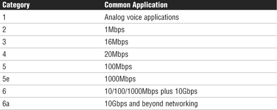
Coaxial cable, or coax as it is commonly called, has been around for a long time. Coax found success in both TV signal transmission and network implementations. As shown in Figure 2.2, coax is constructed with a copper core at the center that carries the signal, plastic insulation, braided metal shielding, and an outer plastic covering. Coaxial cable is constructed in this way to add resistance to attenuation (the loss of signal strength as the signal travels over distance), crosstalk (the degradation of a signal, caused by signals from other cables running close to it), and EMI. Two types of coax are used in networking: thin coax, also known as thinnet, and thick coax, also known as thicknet. Neither is particularly popular anymore, but you are most likely to encounter thin coax. Thick coax was used primarily for backbone cable. It could be run through plenum spaces because it offered significant resistance to EMI and crosstalk and could run in lengths up to 500 meters. Thick coax offers speeds up to 10Mbps, far too slow for today’s network environments.
FIGURE 2.2 Coaxial cabling.
Thin Coax
Thin coax is much more likely to be seen than thick coax in today’s networks, but it isn’t common. Thin coax is only .25 inches in diameter, making it fairly easy to install. Unfortunately, one of the disadvantages of all thin coax types is that they are prone to cable breaks, which increase the difficulty when installing and troubleshooting coaxial-based networks.
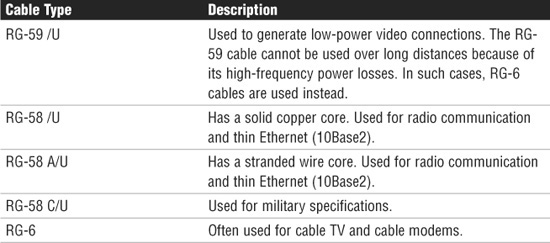
Several types of thin coax cable exist, each of which has a specific use. Table 2.2 summarizes these categories.
Table 2.2 Thin Coax Categories
Fiber-Optic Cable
In many ways, fiber-optic media addresses the shortcomings of copper-based media. Because fiber-based media use light transmissions instead of electronic pulses, threats such as EMI, crosstalk, and attenuation become nonissues. Fiber is well suited for the transfer of data, video, and voice transmissions. In addition, fiber-optic is the most secure of all cable media. Anyone trying to access data signals on a fiber-optic cable must physically tap into the medium. Given the composition of the cable, this is a particularly difficult task.
Unfortunately, despite the advantages of fiber-based media over copper, it still does not enjoy the popularity of twisted-pair cabling. The moderately difficult installation and maintenance procedures of fiber often require skilled technicians with specialized tools. Furthermore, the cost of a fiber-based solution limits the number of organizations that can afford to implement it. Another sometimes hidden drawback of implementing a fiber solution is the cost of retrofitting existing network equipment. Fiber is incompatible with most electronic network equipment. This means that you have to purchase fiber-compatible network hardware.
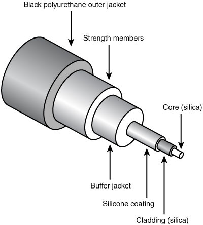
As shown in Figure 2.3, fiber-optic cable is composed of a core glass fiber surrounded by cladding. An insulated covering then surrounds both of these within an outer protective sheath.
FIGURE 2.3 Fiber-optic cabling.
Two types of fiber-optic cable are available:
![]() Multimode fiber: Many beams of light travel through the cable, bouncing off the cable walls. This strategy actually weakens the signal, reducing the length and speed at which the data signal can travel.
Multimode fiber: Many beams of light travel through the cable, bouncing off the cable walls. This strategy actually weakens the signal, reducing the length and speed at which the data signal can travel.
![]() Single-mode fiber: Uses a single direct beam of light, thus allowing for greater distances and increased transfer speeds.
Single-mode fiber: Uses a single direct beam of light, thus allowing for greater distances and increased transfer speeds.
Some of the common types of fiber-optic cable include the following:
![]() 62.5-micron core/125-micron cladding multimode
62.5-micron core/125-micron cladding multimode
![]() 50-micron core/125-micron cladding multimode
50-micron core/125-micron cladding multimode
![]() 8.3-micron core/125-micron cladding single mode
8.3-micron core/125-micron cladding single mode
In the ever-increasing search for bandwidth that will keep pace with the demands of modern applications, fiber-optic cables are sure to play a key role.
Plenum Cables
Plenum is the mysterious space that resides between the false, or drop, ceiling and the true ceiling. This space typically is used for air conditioning and heating ducts. It might also hold a myriad of cables, including telephone, electrical, and networking. The cables that occupy this space must be plenum-rated. Plenum cables are coated with a nonflammable material, often Teflon or Kynar, and they do not give off toxic fumes if they catch fire. As you might imagine, plenum-rated cables cost more than regular cables, but they are mandatory when cables are not run through a conduit. As a bonus, plenum-rated cables suffer from less attenuation than nonplenum cables.
Media Connectors
A variety of connectors are used with the associated network media. Media connectors attach to the transmission media and allow the physical connection into the computing device. For the Network+ exam, you will need to be able to identify the connectors associated with a specific medium. The following sections describe the connectors and associated media.
BNC Connectors
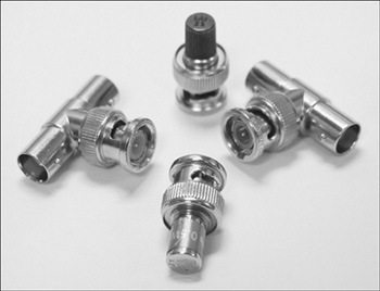
BNC connectors are associated with coaxial media and 10Base2 networks. BNC connectors are not as common as they once were, but they still are used on some networks, older network cards, and older hubs. Common BNC connectors include a barrel connector, T-connector, and terminators. Figure 2.4 shows two terminators (top and bottom) and two T-connectors (left and right).
FIGURE 2.4 BNC connectors.
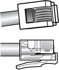
RJ-11 Connectors
RJ- (registered jack) 11 connectors are small plastic connectors used on telephone cables. They have capacity for six small pins. However, in many cases, not all the pins are used. For example, a standard telephone connection uses only two pins, and a cable used for a DSL modem connection uses four.
RJ-11 connectors are somewhat similar to RJ-45 connectors, which are discussed next, although they are a little smaller. Both RJ-11 and RJ-45 connectors have a small plastic flange on top of the connector to ensure a secure connection. Figure 2.5 shows two views of an RJ-11 connector.
FIGURE 2.5 RJ-11 connectors.
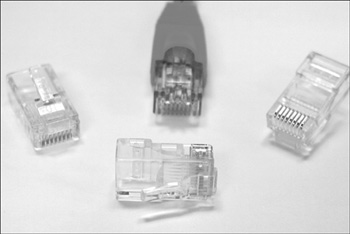
RJ-45 Connectors
RJ-45 connectors, shown in Figure 2.6, are the ones you are most likely to encounter in your network travels. RJ-45 connectors are used with twisted-pair cabling, the most prevalent network cable in use today. RJ-45 connectors resemble the aforementioned RJ-11 phone jacks, but they support up to eight wires instead of the six supported by RJ-11 connectors. RJ-45 connectors are also larger.
FIGURE 2.6 RJ-45 connectors.
F-Type Connectors and RG-59 and RG-6
F-Type connectors, shown in Figure 2.7, are screw-on connections used to attach coaxial cable to devices. This includes RG-59 and RG-6 cables. In the world of modern networking, F-Type connectors are most commonly associated with connecting Internet modems to cable or satellite Internet service providers’ (ISPs’) equipment. However, they are also used to connect to some proprietary peripherals.
FIGURE 2.7 F-Type connector.
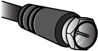
F-Type connectors have a “nut” on the connection that provides something to grip as the connection is tightened by hand. If necessary, this nut can be also be lightly gripped with pliers to aid disconnection.
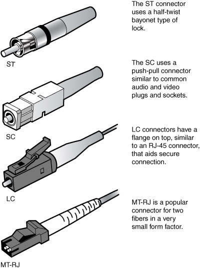
Fiber Connectors
A variety of connectors are associated with fiber cabling, and there are several ways of connecting them. These include bayonet, snap-lock, and push-pull connectors. Figure 2.8 shows the fiber connectors identified in the CompTIA Network+ objectives.
FIGURE 2.8 Fiber connectors. (Reproduced with permission from Computer Desktop Encyclopedia. 1981–2005. The Computer Language Company, Inc. All rights reserved.)
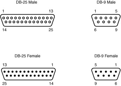
RS-232 Standard
RS-232 (Recommended Standard 232) is a TIA/EIA standard for serial transmission between computers and peripheral devices such as modems, mice, and keyboards. The RS-232 standard was introduced way back in the 1960s and is still used today. However, peripheral devices are more commonly connected using USB or wireless connections. RS-232 commonly uses a 25-pin DB-25 connector or a nine-pin DB-9 connector. Figure 2.9 shows an example of RS-232 standard connectors.
FIGURE 2.9 RS-232 DB connectors.
Of course, serial connectors need to attach to a serial cable. Serial cables often use four to six wires to attach to the connectors. Similar to other cable types, they can come in both an unshielded and shielded type. Shielding reduces interference and EMI for the cable. The distance that a length of serial cable can run varies somewhat. It depends on the characteristics of the serial port and, of course, the quality of the serial cable. The RS-232 standard specifies serial cable distances up to 50 feet and a transfer speed up to 20kbps. Other serial standards increase this range and speed.
IEEE 1394
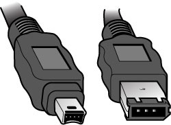
The IEEE 1394 interface, also known as FireWire, is more commonly associated with the attachment of peripheral devices, such as digital cameras or printers, than network connections. However, it is possible to create small networks with IEEE 1394 cables. The IEEE 1394 interface comes in a four- or six-pin version, both of which are shown in Figure 2.10.
FIGURE 2.10 Four-pin (left) and six-pin (right) IEEE 1394 (FireWire) connectors.
Universal Serial Bus (USB)
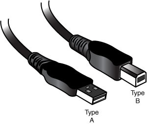
Universal Serial Bus (USB) ports are now an extremely common sight on both desktop and laptop computer systems. Like IEEE 1394, USB is associated more with connecting consumer peripherals such as MP3 players and digital cameras than with networking. However, many manufacturers now make wireless network cards that plug directly into a USB port. Most desktop and laptop computers have between two and four USB ports, but USB hubs are available that provide additional ports if required.
A number of connectors are associated with USB ports, but the two most popular are Type A and Type B. Type A connectors are the more common of the two and are the type used on PCs. Although many peripheral devices also use a Type A connector, an increasing number now use a Type B. Figure 2.11 shows a Type A connector (left) and a Type B connector (right).
FIGURE 2.11 Type A (left) and Type B (right) USB connectors.
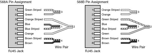
568A and 568B Wiring Standards
568A and 568B are telecommunications standards from TIA and EIA. These 568 standards specify the pin arrangements for the RJ-45 connectors on UTP or STP cables. The number 568 refers to the order in which the wires within the Category 5 cable are terminated and attached to the connector.
The 568A and 568B standards are quite similar; the difference is the order in which the pins are terminated. The signal is the same for both. Both are used for patch cords in an Ethernet network.
Network media may not always come with connectors attached, or you might need to make custom length cables. This is when you need to know something about how these standards actually work. Before you can crimp on the connectors, you need to know in which order the individual wires will be attached to the connector. Figure 2.12 shows the pin number assignments for the 568A and 568B standards. Pin numbers are read left to right, with the connector tab facing down.
FIGURE 2.12 Pin assignments for the 568A and 568B standards.
Straight Versus Crossover Cable
Two types of cables are used to connect devices to hubs and switches: crossover cables and straight-through cables. The difference between the two types is that in a crossover cable, two of the wires are crossed; in a straight-through cable, all the wires run straight through.
Specifically, in a crossover cable, wires 1 and 3 and wires 2 and 6 are crossed. Wire 1 at one end becomes wire 3 at the other end, wire 2 at one end becomes wire 6 at the other end, and vice versa in both cases. You can see the differences between the two cables in Figures 2.13 and 2.14. Figure 2.13 shows the pinouts for a straight-through cable, and Figure 2.14 shows the pinouts for a crossover cable.
FIGURE 2.13 Pinouts for a straight-through twisted-pair cable.
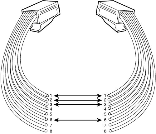
FIGURE 2.14 Pinouts for a crossover twisted-pair cable.
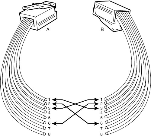
To make a crossover Ethernet cable, you need to use both the 568A and 568B standards. One end of the cable can be wired according to the 568A standard, and the other with the 568B standard.
Rollover and Loopback Cables
The rollover cable is a Cisco Systems proprietary cable used to connect a computer system to a router or switch console port. The rollover cable resembles an Ethernet UTP cable; however, it is not possible to use it on anything but Cisco equipment. Like UTP cable, the rollover cable has eight wires inside and an RJ-45 connector on each end that connect to the router and the computer port.
As far as pinouts are concerned, pin 1 on one end of the rollover cable connects to pin 8 at the other end of the cable. Similarly, pin 2 connects to pin 7, and so on. The ends are simply reversed. As soon as one end of the rollover cable is connected to the PC and the other to the Cisco terminal, the Cisco equipment can be accessed from the computer system using a program such as HyperTerminal, which is included with Microsoft Windows products.
Loopback Cable
A loopback cable, also known as a plug, is used to test and isolate network problems. If made correctly, the loopback plug causes the link light on a device such as a network interface card (NIC) to come on. This is a very quick and cheap way to test simple network cabling problems. The loopback plug redirects outgoing data signals to the system. The system then believes that it is both sending and receiving data.
The loopback cable is basically a troubleshooting tool used to test the device to see if it is sending and receiving properly. It uses UTP cable and RJ-45 connectors.
Components of Wiring Distribution
So far, this chapter has examined various types of media and the associated connectors. This section looks at wiring in the closet, the place in networks where you connect the cables and networking devices. These rooms have many names, including the wiring closet, the telecommunications room, and the network operations center (NOC). These telecommunications rooms contain the key network devices, such as the hubs, routers, switches, and servers. These rooms also contain the network media, such as patch cables that connect network devices to horizontal cables and the rest of the network.
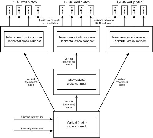
Network Cross-Connects
The cable that runs throughout a network can be divided into two distinct sections:
![]() Horizontal cabling: Connects client systems to the network.
Horizontal cabling: Connects client systems to the network.
![]() Vertical (backbone) cabling: Runs between floors to connect different locations on the network.
Vertical (backbone) cabling: Runs between floors to connect different locations on the network.
Both of these cable types have to be consolidated and distributed from a location—a wiring closet.
There are three types of cable distribution:
![]() Vertical or main cross-connect: The location where outside cables enter the building for distribution. This can include Internet and phone cabling.
Vertical or main cross-connect: The location where outside cables enter the building for distribution. This can include Internet and phone cabling.
![]() Horizontal cross-connect: The location where the vertical and horizontal connections meet.
Horizontal cross-connect: The location where the vertical and horizontal connections meet.
![]() Intermediate cross-connect: Typically used in larger networks. Provides an intermediate cross-connect between the main and horizontal cross-connects.
Intermediate cross-connect: Typically used in larger networks. Provides an intermediate cross-connect between the main and horizontal cross-connects.
The term cross-connect refers to the point where the cables running throughout the network meet and are connected.
Horizontal Cabling
Within the telecommunications room, horizontal cabling connects the telecommunications room to the end user, as shown in Figure 2.15. Specifically, the horizontal cabling extends from the telecommunications outlet, or a network outlet with RJ-45 connectors, at the client end. It includes all cable from that outlet to the telecommunications room to the horizontal cross-connect—the distribution point for the horizontal cable. The horizontal cross-connect includes all connecting hardware, such as patch panels and patch cords. The horizontal cross-connect is the termination point for all network horizontal cables.
FIGURE 2.15 Horizontal cabling.
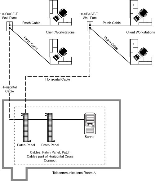
Horizontal cabling runs within walls and ceilings and therefore is called permanent cable or structure cable. The length of cable running from the horizontal connects and the telecommunication outlet on the client side should not exceed 90 meters. Patch cables used typically should not exceed 5 meters. This is due to the 100-meter distance limitation of most UTP cable.
Vertical Cable
Vertical cable, or backbone cable, refers to the media used to connect telecommunications rooms, server rooms, and remote locations and offices. Vertical cable may be used to connect locations outside the local LAN that require high-speed connections. Therefore, vertical cable is often fiber-optic cable or high-speed UTP cable. Figure 2.16 shows the relationship between horizontal cable and vertical cable.
FIGURE 2.16 Vertical and horizontal cabling.
Patch Panels
If you’ve ever looked in a telecommunications room, you have probably seen a distribution block, more commonly called a patch panel. A patch panel is a freestanding or wall-mounted unit with a number of RJ-45 port connections on the front. In a way, it looks like a wall-mounted hub without the light-emitting diodes (LEDs). The patch panel provides a connection point between network equipment such as hubs and switches and the ports to which PCs are connected, which normally are distributed throughout a building.
Also found in a wiring closet is the punchdown block. The wires from a telephony or UTP cable are attached to the punchdown block using a punchdown tool. To use the punchdown tool, you place the wires in the tip of the tool and push it into the connectors attached to the punchdown block. The wire insulation is stripped, and the wires are firmly embedded into the metal connector. Because the connector strips the insulation on the wire, it is known rather grandiosely as an insulation displacement connector (IDC). Figure 2.17 shows a punchdown tool placing wires into an IDC of a patch panel.
FIGURE 2.17 Punchdown tool inserting wires into an IDC.
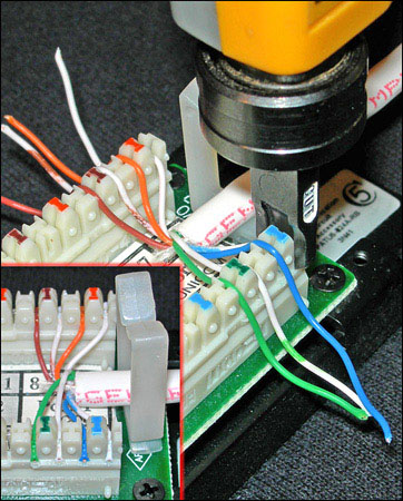
Using a punchdown tool is much faster than using wire strippers to prepare each individual wire and then twisting the wire around a connection pole or tightening a screw to hold the wire in place. In many environments, cable tasks are left to a specialized cable contractor. In others, the administrator is the one who must connect wires to a patch panel.
Type 66 and Type 110 Punchdown Blocks
Two main types of punchdown blocks are used—type 66 and type 110. Type 66 is an older design and is not as widely used as type 110. The 66 is a block used to connect wiring for telephone systems and other low-speed network systems. Like all punchdown blocks, a punchdown tool is used to force solid wire into metal slots on the 66 block. See Figure 2.17.
The 66 block has 50 rows of IDC contacts to accommodate 25-pair twisted pair cable. Block 66 was used primarily for voice communication. Although it is approved for Category 5, it may not be suitable due to crosstalk problems.
In the network wiring closet, the 110 block is used to connect network cable to patch panels. 110 connections can also be used at the other end of the network cable at the RJ-45 wall jack. 110 blocks are preferred over the older 66 blocks, the 110 block improves on the 66 block by supporting higher frequencies and less crosstalk. Therefore, it supports higher-speed networks and higher grade twisted pair cable.
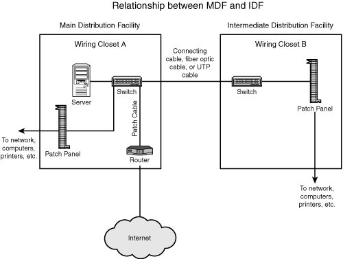
MDF and IDF
The preceding section looked at wiring closets. Two types of wiring closets are Main Distribution Frame (MDF) and Intermediate Distribution Frame (IDF). The main wiring closet for a network typically holds the majority of the network gear, including routers, switches, wiring, servers, and more. This is also typically the wiring closet where outside lines run into the network. This main wiring closet is known as the MDF. One of the key components in the MDF is a primary patch panel. The network connector jacks attached to this patch panel lead out to the building for network connections.
In some networks, multiple wiring closets are used. When this is the case, the MDF connects to these secondary wiring closets, or IDFs, using a backbone cable. This backbone cable may be UTP, fiber, or even coaxial. In today’s high-speed networks, UTP Gigabit Ethernet or high-speed fiber are the media of choice. Figure 2.18 shows the relationship between the MDF and the IDF.
FIGURE 2.18 The relationship between MDFs and IDFs.
Demarc, Demarc Extension, and Smart Jacks
A network’s demarcation point is the connection point between the operator’s part of the network and the customer’s portion of the network. This point is important for network administrators, because it distinguishes the portion of the network that the customer is responsible for from the section the owner is responsible for. As an example, for those who have high-speed Internet, the boundary between the customer’s premises and the ISP typically is mounted on the wall on the side of the home. However, high-speed service providers support everything from the cable modem back to their main distribution center. This is why, if a modem fails, it is replaced by the ISP and not by the customer. This is true for the wiring to that point as well.
As mentioned, knowing where the demarcation point is is essential, because it marks the point between where the customer (or administrator) is responsible and where the owner is. It also identifies the point at which the customer is responsible should a problem occur and who should pay for that problem. The ISP is responsible for ensuring that the network is functional up to the demarcation point. The customer/administrator is responsible for ensuring that everything from that point is operational.
The demarcation point is the point at which the ISP places its services in your network. There is not always a choice of where this demarcation is placed. This means that a company might have six floors of offices and the demarcation point is in the basement—impractical for the network. This is when you need a demarcation extension, which extends the demarcation point to a more functional location. This might sound simple, but it involves knowledge of cabling distances and other infrastructure needs. The demarcation extension might be the responsibility of the administrator, or for a fee, owners might provide extension services.
As you might imagine, you need some form of hardware at the demarcation point. This is the smart jack, also known as the Network Interface Device (NID). The smart jack performs several primary functions:
![]() Loopback feature: The loopback feature is built into the smart jack. Like the Ethernet loopback cable, it is used for testing purposes. In this case, the loopback feature allows for remote testing so that technicians do not always need to be called to visit the local network to isolate problems.
Loopback feature: The loopback feature is built into the smart jack. Like the Ethernet loopback cable, it is used for testing purposes. In this case, the loopback feature allows for remote testing so that technicians do not always need to be called to visit the local network to isolate problems.
![]() Signal amplification: The smart jack can amplify signals. This feature is similar to that of the function of repeaters in an Ethernet network.
Signal amplification: The smart jack can amplify signals. This feature is similar to that of the function of repeaters in an Ethernet network.
![]() Surge protection: Lighting and other environmental conditions can cause electrical surges that can quickly damage equipment. Many smart jacks include protection from environmental situations.
Surge protection: Lighting and other environmental conditions can cause electrical surges that can quickly damage equipment. Many smart jacks include protection from environmental situations.
![]() Remote alarms: Smart jacks typically include an alarm that allows the owner to identify if something goes wrong with the smart jack and therefore the connections at the demarcation point.
Remote alarms: Smart jacks typically include an alarm that allows the owner to identify if something goes wrong with the smart jack and therefore the connections at the demarcation point.
Verify Wiring Installation and Termination
After a segment of network cable has been placed where it needs to go, whether run through the plenum or connecting a patch cable, the final task is wiring termination. Termination is the process of connecting the network cable to the wall jack, plug, or patch panel. Termination generally is a straightforward process. You can quickly see if the wiring and termination worked if the LED on the connected network card is lit. Also, if you’re connecting a client system, you will be able to ping other devices on the network if all is working.
If you have run the wiring and completed termination, but a system cannot access the network and the link light is not lit, you should look for a few things when troubleshooting the wiring installation and termination.
Verify that the termination and wiring installation link light on the device (switch/NIC) is not lit:
![]() If you’re connecting a patch cable to a PC or switch, and no link light is lit, verify that the patch cable is good by switching it with a known working one.
If you’re connecting a patch cable to a PC or switch, and no link light is lit, verify that the patch cable is good by switching it with a known working one.
![]() If it is a homemade patch cable, ensure that the RJ-45 connector is properly attached.
If it is a homemade patch cable, ensure that the RJ-45 connector is properly attached.
![]() Ensure that the RJ-45 connector is properly seated in the wall jack and NIC or switch port.
Ensure that the RJ-45 connector is properly seated in the wall jack and NIC or switch port.
![]() If no link light is lit when you connect to a switch, change to another port on the switch. Sometimes a single port can be faulty.
If no link light is lit when you connect to a switch, change to another port on the switch. Sometimes a single port can be faulty.
![]() Verify that the correct patch cable is being used. It is possible that a rollover cable or crossover cable has been used accidentally.
Verify that the correct patch cable is being used. It is possible that a rollover cable or crossover cable has been used accidentally.
![]() Verify that the cables used are the correct standard. For example, the patch cable should be a 568A or 568B.
Verify that the cables used are the correct standard. For example, the patch cable should be a 568A or 568B.
If the link light on a device is lit and intermittent problems occur, check the following:
![]() Try replacing the cable with a known working one.
Try replacing the cable with a known working one.
![]() Verify where the network cable is run. Ensure that a plenum-rated cable is used if it is running through ceilings or ductwork.
Verify where the network cable is run. Ensure that a plenum-rated cable is used if it is running through ceilings or ductwork.
![]() Look for heavy bends or partial breaks in the network cable.
Look for heavy bends or partial breaks in the network cable.
![]() Verify that shielded cabling is being used in areas of potentially high interference.
Verify that shielded cabling is being used in areas of potentially high interference.
![]() Check the length of the cable run. Remember, the total run of cable should be about 100 meters. If the patch cable or the cable between the wall jack and the wiring closet is too long, intermittent signals can occur.
Check the length of the cable run. Remember, the total run of cable should be about 100 meters. If the patch cable or the cable between the wall jack and the wiring closet is too long, intermittent signals can occur.
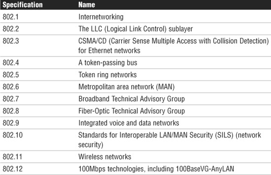
IEEE and Overview of Networking Standards
The Institute of Electrical and Electronics Engineers (IEEE) developed a series of networking standards to ensure that networking technologies developed by respective manufacturers are compatible. This means that the cabling, networking devices, and protocols are all interchangeable when designed under the banner of a specific IEEE standard. Table 2.3 summarizes the IEEE 802 networking standards.
Table 2.3 IEEE 802 Networking Standards
Each of these IEEE specifications outlines specific characteristics for LAN networking, including the speed, topology, cabling, and access method. The following sections outline the key features of the standards you are likely to encounter on the Network+ exam.
IEEE 802.2 Standard
The 802.2 standard, called Logical Link Control (LLC), manages data flow control and error control for the other IEEE LAN standards. Data flow control regulates how much data can be transmitted in a certain amount of time. Error control refers to the recognition and notification of damaged signals. The LLC layer is discussed more in Chapter 4, “OSI Model and Network Protocols.”
IEEE 802.3x Standard Characteristics
The IEEE 802.3 standards define a range of networking systems that are based on the original Ethernet standard. The variations for each standard include speed, access method, physical topology, and implementation considerations. The next sections review some of the characteristics specified within each standard.
Speed
Many factors contribute to the speed of a network. The standard defines the maximum speed of a networking system. The speed normally is measured in megabits per second (Mbps), although some faster network systems use gigabits per second (Gbps, where 1Gbps is equivalent to 1000Mbps).
Some networks are faster than others. For example, a token ring (802.5) network has a maximum speed of 16Mbps. Many Ethernet networks (802.3 variants) now operate at 100Mbps and far beyond. However, the maximum speed attainable on a network can be affected by many factors. Networks that achieve 100% of their potential bandwidth are few and far between.
Access Methods
Access methods govern how systems access the network media and send data. Access methods are necessary to ensure that systems on the network can communicate with each other. Without an access method, two systems could communicate at the exclusion of every other system. Access methods ensure that everyone gets an opportunity to use the network.
Several access methods are used in networks; the most popular are CSMA/CD and CSMA/CA.
CSMA/CD
Carrier Sense Multiple Access/Collision Detection (CSMA/CD), which is defined in the IEEE 802.3 standard, is the most common media access method because it is associated with 802.3 Ethernet networking, which is by far the most popular networking system.
On a network that uses CSMA/CD, when a system wants to send data to another system, it first checks to see whether the network medium is free. It must do this because each piece of network medium used in a LAN can carry only one signal at a time. If the sending node detects that the medium is free, it transmits, and the data is sent to the destination. It seems simple.
Now, if it always worked like this, you wouldn’t need the CD part of CSMA/CD. Unfortunately, in networking, as in life, things do not always go as planned. The problem arises when two systems attempt to transmit at exactly the same time. It might seem unlikely that two systems would pick the exact same moment to send data, but you are dealing with communications that occur many times in a single second—and most networks have more than two machines. Imagine that 200 people are in a room. The room is silent, but then two people decide to say something at exactly the same time. Before they start to speak, they check (listen) to see whether someone else is speaking; because no one else is speaking, they begin to talk. The result is two people speaking at the same time, which is similar to a network collision.
Collision detection works by detecting fragments of the transmission on the network media that result when two systems try to talk at the same time. The two systems wait for a randomly calculated amount of time before attempting to transmit again. This amount of time—a matter of milliseconds—is known as the backoff period or jam signal.
When the backoff period has elapsed, the system attempts to transmit again. If the system doesn’t succeed on the second attempt, it keeps retrying until it gives up and reports an error.
The upside of CSMA/CD is that it has relatively low overhead, meaning that not much is involved in the workings of the system. The downside is that as more systems are added to the network, more collisions occur, and the network becomes slower. The performance of a network that uses CSMA/CD degrades exponentially as more systems are added. Its low overhead means that CSMA/CD systems theoretically can achieve greater speeds than high-overhead systems, such as token passing. However, because collisions take place, the chance of all that speed translating into usable bandwidth is relatively low.
Despite its problems, CSMA/CD is an efficient system. As a result, rather than replace it with some other technology, workarounds have been created that reduce the likelihood of collisions. One such strategy is the use of network switches that create multiple collision domains and therefore reduce the impact of collisions on performance.
CSMA/CA
Instead of collision detection, as with CSMA/CD, the Carrier Sense Multiple Access with Collision Avoidance (CSMA/CA) access method uses signal avoidance rather than detection. In a networked environment, CSMA/CA is the access mechanism used in Apple’s LocalTalk network and with the 802.11 wireless standards.
On CSMA/CA >networks, each computer signals its intent to transmit data signals before any data is actually sent. When a networked system detects a potential collision, it waits before sending the transmission, allowing systems to avoid transmission collisions. The CSMA/CA access method uses a random backoff time that determines how long to wait before trying to send data on the network. When the backoff time expires, the system again “listens” to verify a clear channel on which to transmit. If the medium is still busy, another backoff interval is initiated that is less than the first. The process continues until the wait time reaches zero, and the medium is clear.
CSMA/CA uses a broadcast method to signal its intention to transmit data. Network broadcasts create a considerable amount of network traffic and can cause network congestion, which could slow down the entire network. Because CSMA/CD and CSMA/CA differ only in terms of detection and avoidance, they have similar advantages and disadvantages.
Topology
As discussed in Chapter 1, topologies dictate both the physical and logical layouts of the network. Remember that topologies include bus, star, ring, mesh, and wireless. Each of the IEEE LAN standards can be implemented by using the topology specified within the standard. Some standards, such as 802.3 (Ethernet), have multiple physical topologies but always use the same logical topology. Token Ring has two possible physical topologies and a single logical topology.
Media
Each IEEE specification defines what media are available to transport the signal around the network. The term media, which is the plural of medium, generically describes the methods by which data is transported from one point to another. Common network media types include twisted-pair cable, coaxial cable, infrared, radio frequency, and fiber-optic cable.
Baseband Versus Broadband Signaling
Before delving any further into 802.3 standards, you should understand the difference between baseband and broadband signaling. Two types of signaling methods are used to transmit information over network media: baseband and broadband.
Baseband
Baseband transmissions typically use digital signaling over a single wire; the transmissions themselves take the form of either electrical pulses or light. The digital signal used in baseband transmission occupies the entire bandwidth of the network medium to transmit a single data signal. Baseband communication is bidirectional, allowing computers to both send and receive data using a single cable; however, the sending and receiving cannot occur on the same wire at the same time.
Using baseband transmissions, it is possible to transmit multiple signals on a single cable by using a process known as multiplexing. Baseband uses Time Division Multiplexing (TDM), which divides a single channel into time slots. The key thing about TDM is that it doesn’t change how baseband transmission works—only how data is placed on the cable.
Broadband
Whereas baseband uses digital signaling, broadband uses analog signals in the form of optical or electromagnetic waves over multiple transmission frequencies. For signals to be both sent and received, the transmission medium must be split into two channels. Alternatively, two cables can be used—one to send and one to receive transmissions.
Multiple channels are created in a broadband system by using a multiplexing technique known as Frequency Division Multiplexing (FDM). FDM allows broadband media to accommodate traffic going in different directions on a single medium at the same time.
802.3 Ethernet Standards
Now that you know some of the characteristics defined by the IEEE standards, let’s examine the standards themselves. Make sure that you are completely familiar with the information provided in each of the following sections before you take the Network+ exam.
10BaseT
The 10BaseT LAN standard specifies an Ethernet network that commonly uses unshielded twisted-pair cable. However, in some implementations that require a greater resistance to interference and attenuation, shielded twisted pair (STP) can be used. STP has extra shielding to combat interference.
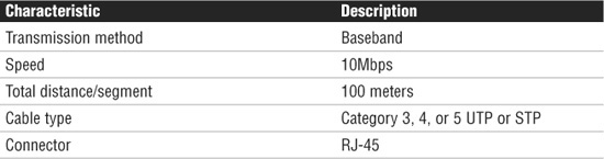
10BaseT uses baseband transmission and has a maximum physical segment length of 100 meters. Repeaters are sometimes used to extend the maximum segment length, although the repeating capability is now often built into networking devices used in twisted-pair networks. 10BaseT specifies transmission speeds of 10Mbps and can use several categories of UTP cable, including Categories 3, 4, and 5 (all of which use RJ-45 connectors). 10BaseT takes advantage of the multiple wires inside twisted-pair cable to create independent transmit and receive paths, which means that full-duplex mode can optionally be supported. The maximum number of computers supported on a 10BaseT network is 1,024.
All 10BaseT networks use a point-to-point network design, with one end of the connection attaching to the network card and the other to a hub or switch. These point-to-point connections result in a physical star topology. Chapter 3, “Networking Components and Devices,” provides more information on the devices used in twisted-pair networks.
Table 2.4 summarizes the characteristics of the 10BaseT standard.
Table 2.4 Summary of 10BaseT Characteristics
10BaseFL
10BaseFL is an implementation of 10Mbps Ethernet over fiber-optic cabling. The primary advantage of 10BaseFL over 10BaseT is that it can be used over distances up to 2 km. However, given the availability of other, faster networking standards, such as 100BaseFX (discussed later), you are unlikely to encounter many 10BaseFL implementations.
Fast Ethernet
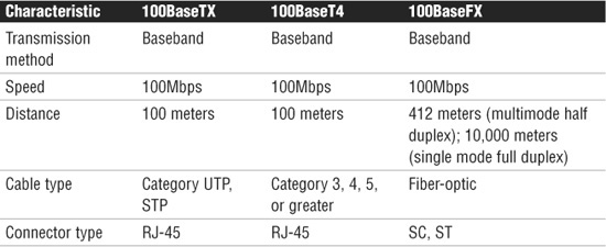
There was a time when 10Mbps networks were considered fast enough, but those days are long gone. Today, companies and home users alike demand more bandwidth than is available with 10Mbps network solutions. For such networks, Fast Ethernet is the most commonly used network design. Fast Ethernet standards are specified in the IEEE 802.3u standard. Three standards are defined by 802.3u: 100BaseTX, 100BaseT4, and 100BaseFX.
100BaseTX
100BaseTX is known as Fast Ethernet networking design and is one of three 802.3u standards. As its name suggests, 100BaseTX transmits network data at speeds up to 100Mbps, the speeds at which most LANs operate today. 100BaseTX is most often implemented with UTP cable, but it can use STP; therefore, it suffers from the same 100-meter distance limitations as other UTP-based networks. 100BaseTX uses Category 5 UTP cable, and, like 10BaseT, it uses independent transmit and receive paths and therefore can support full-duplex operation. 100BaseTX is, without question, the most common Fast Ethernet standard.
100BaseT4
100BaseT4 is the second Fast Ethernet standard specified under 802.3u. It can use Category 3, 4, and 5 UTP cable, and it uses all four of the available pairs of wires within the cable, limiting full-duplex transfer. 100BaseT4 is similar in other respects to 100BaseTX: Its cable distance is limited to 100 meters, and its maximum transfer speed is 100Mbps. 100BaseT4 is not widely implemented, but it is sometimes used in environments with existing cable, such as Category 3 cable. In such a situation, you can use 100BaseT4 instead of replacing the Category 3 cable with Category 5 UTP.
100BaseFX
100BaseFX is the IEEE standard for running Fast Ethernet over fiber-optic cable. Due to the expense of fiber implementations, 100BaseFX is largely limited to use as a network backbone. 100BaseFX can use two-strand multimode fiber or single-mode fiber media. The maximum segment length for half-duplex multimode fiber is 412 meters, but this maximum increases to an impressive 10,000 meters for full-duplex single-mode fiber. 100BaseFX often uses SC or ST fiber connectors. Table 2.5 shows how 100BaseFX compares with other 100Base technologies.
Fast Ethernet Comparison
Table 2.5 summarizes the characteristics of the 802.3u Fast Ethernet specifications.
Table 2.5 Summary of 802.3u Fast Ethernet Characteristics
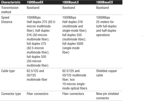
Gigabit Ethernet: 1000BaseX
Gigabit Ethernet, 1000BaseX, is another variation on the 802.3 standard and is given its own identifier: 802.3z. Gigabit Ethernet offers transfer rates of up to 1000Mbps and is most often associated with fiber cable, but not always. 1000BaseX refers collectively to three distinct standards: 1000BaseLX, 1000BaseSX, and 1000BaseCX.
Both 1000BaseSX and 1000BaseLX are laser standards used over fiber. SX refers to short wavelength laser, and LX refers to long wavelength laser. Both the SX and LX wave lasers can be supported over two types of multimode fiber-optic cable: fibers of 62.5-micron and 50-micron diameters. Only LX wave lasers support the use of single-mode fiber.
The differences between 1000BaseLX and 1000BaseSX have to do with cost and transmission distance. 1000BaseLX can transmit over 316 meters in half duplex for both multimode fiber and single-mode fiber, 550 meters for full-duplex multimode fiber, and 5,000 meters for full-duplex single-mode fiber. Although 1000BaseSX is less expensive than 1000BaseLX, it cannot match the distances achieved by 1000BaseLX.
1000BaseCX moves away from fiber cable and uses shielded copper wire. Segment lengths in 1000BaseCX are severely restricted; the maximum cable distance is 25 meters. Because of the restricted cable lengths, 1000BaseCX networks are not widely implemented. Table 2.6 summarizes the characteristics of Gigabit Ethernet 802.3z standards.
Table 2.6 Summary of IEEE 802.3z Gigabit Ethernet Characteristics
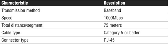
1000BaseT
1000BaseT, sometimes called 1000BaseTX, is another Gigabit Ethernet standard, and it is given the IEEE 802.3ab designation. The 802.3ab standard specifies Gigabit Ethernet over Category 5 UTP cable. The standard allows for full-duplex transmission using the four pairs of twisted cable. To reach speeds of 1000Mbps over copper, a data transmission speed of 250Mbps is achieved over each pair of twisted-pair cable. Table 2.7 summarizes the characteristics of 1000BaseT.
Table 2.7 Summary of 1000BaseT Characteristics
10 Gigabit Ethernet
In the never-ending quest for faster data transmission rates, network standards are always being pushed to the next level. In today’s networking environments, that level is 10 Gigabit Ethernet, also called 10GbE. As the name suggests, 10GbE can provide data transmission rates of up to 10 gigabits per second. That’s 10000 Mbps, or 100 times faster than most modern LAN implementations. A number of 10GbE implementations exist. This section explores the standards highlighted in the Network+ objectives.
Designed primarily as a WAN and MAN connectivity medium, 10GbE was ratified as the IEEE 802.3ae standard in June 2002. Many networking hardware manufacturers now market 10GbE equipment. Although 10GbE network implementations are very expensive, companies such as ISPs that require extremely high-speed networks have been relatively quick to implement 10GbE.
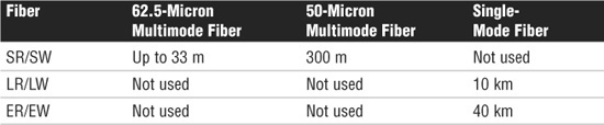
10GBaseSR/SW
The IEEE 802.3ae 10 Gigabit Ethernet specification includes a serial interface referred to as 10GBaseS (the S stands for short wavelength) that is designed for transmission on multimode fiber. Two Ethernet standards that fall in the S category are 10GBaseSR and 10GBaseSW. Both SR and SW are designed for deployment over short-wavelength multimode fiber. The distance range for both classifications ranges from as little as 2 meters to 300 meters. The difference between the two classifications is that SR is designed for use over dark fiber. In the networking world, dark fiber refers to “unlit” fiber or fiber that is not in use and connected to any other equipment. The 10GBaseSW standard is designed for longer-distance data communications and connects to Synchronous Optical Network (SONET) equipment. SONET is a fiber-optic transmission system for high-speed digital traffic and is discussed in greater detail in Chapter 6.
10GBaseLR/LW
The 10GBaseLR/LW Ethernet standards are not used over multimode fiber. Instead, they offer greater distances using single-mode fiber. Both the LR and LW standards are designed to be used over long-wavelength single-mode fiber, giving it a potential transmission range of anywhere from 2 meters to 10 kilometers. This transmission range makes the standards available for LAN, MAN, and WAN deployments. As with the previous standards, the LR standard is used with dark fiber, whereas the LW standard is designed to connect to SONET equipment.
10GBaseER/EW
When it comes to WANs that require greater transmission distances, the Ethernet 10GBaseER/EW standards come into play. Both the ER and EW Gigabit standards are deployed with extra-long wavelength single-mode fiber. This medium provides transmission distances ranging from 2 meters to 40 kilometers. As with the previous two standards, ER is deployed over dark fiber, whereas the EW standard is used primarily with SONET equipment. Table 2.8 outlines the characteristics of the 10GBase Ethernet standards.
Table 2.8 Summary of 802.3ae Characteristics
10GBaseT
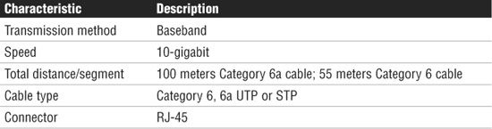
The final standard outlined in the Network+ objectives is the 802.3an Ethernet standard. The 802.3an standard brings 10 gigabit speed to regular copper cabling. Although transmission distances may not be that of fiber, it allows a potential upgrade from 1000 gigabit networking to 10 gigabit networking using the current wiring infrastructure.
The 10GBaseT standard specifies 10-gigabit transmissions over UTP or STP twisted-pair cables. The standard calls for a cable specification of Category 6 or Category 6a. With Category 6, the maximum transmission range is 55 meters; with the augmented Category 6a cable, transmission range increases to 100 meters. Category 6 and 6a cables are specifically designed to reduce attenuation and crosstalk, making 10-gigabit speeds possible. 802.3an specifies regular RJ-45 networking connectors. Table 2.9 outlines the characteristics of the 802.3an standard.
Table 2.9 Summary of 802.3an Characteristics
Review and Test Yourself
The following sections provide you with the opportunity to review what you’ve learned in this chapter and to test yourself.
The Facts
For the exam, don’t forget these key concepts:
![]() RJ-11 connectors are used with standard phone lines and are similar in appearance to RJ-45 connectors used in networking. However, RJ-11 connectors are smaller.
RJ-11 connectors are used with standard phone lines and are similar in appearance to RJ-45 connectors used in networking. However, RJ-11 connectors are smaller.
![]() RJ-45 connectors are used with UTP cabling.
RJ-45 connectors are used with UTP cabling.
![]() F-type connectors are used to connect coaxial cable to devices such as Internet modems.
F-type connectors are used to connect coaxial cable to devices such as Internet modems.
![]() Fiber-optic cabling uses a variety of connectors, but SC and ST are more commonly used than others.
Fiber-optic cabling uses a variety of connectors, but SC and ST are more commonly used than others.
![]() SC and ST connectors are associated with fiber cabling. ST connectors offer a twist-type attachment, whereas SCs have a push-on connector.
SC and ST connectors are associated with fiber cabling. ST connectors offer a twist-type attachment, whereas SCs have a push-on connector.
![]() LC and MT-RJ are other types of fiber-optic connectors.
LC and MT-RJ are other types of fiber-optic connectors.
![]() UTP cabling is the most common type used on today’s networks. For greater speeds, distances, and resistance to interference, fiber-optic cable provides an increasingly affordable alternative.
UTP cabling is the most common type used on today’s networks. For greater speeds, distances, and resistance to interference, fiber-optic cable provides an increasingly affordable alternative.
![]() 10BaseT networks use UTP cable and RJ-45 connectors to transfer data at up to 10Mbps.
10BaseT networks use UTP cable and RJ-45 connectors to transfer data at up to 10Mbps.
![]() 10BaseFL networks use fiber-optic cabling and can span distances of up to 2 km.
10BaseFL networks use fiber-optic cabling and can span distances of up to 2 km.
![]() 100BaseTX networks use RJ-45 connectors and use Category 5 STP or UTP cable.
100BaseTX networks use RJ-45 connectors and use Category 5 STP or UTP cable.
![]() 100BaseT4 networks use Category 3, 4, and 5 cable with RJ-45 connectors.
100BaseT4 networks use Category 3, 4, and 5 cable with RJ-45 connectors.
![]() 100BaseFX uses fiber-optic cable and often uses SC or ST connectors.
100BaseFX uses fiber-optic cable and often uses SC or ST connectors.
![]() 1000BaseSX and 1000BaseLX offer 1000Mbps transfer speeds using fiber-optic cable.
1000BaseSX and 1000BaseLX offer 1000Mbps transfer speeds using fiber-optic cable.
![]() 1000BaseCX offers 1000Mbps transfer speeds over shielded copper cable. Distances are restricted to 25 meters.
1000BaseCX offers 1000Mbps transfer speeds over shielded copper cable. Distances are restricted to 25 meters.
![]() 1000BaseTX offers 1000Mbps transfer speeds over UTP cable up to a maximum of 100 meters.
1000BaseTX offers 1000Mbps transfer speeds over UTP cable up to a maximum of 100 meters.
![]() 10Gbps networks are defined by the IEEE 802.3ae standard.
10Gbps networks are defined by the IEEE 802.3ae standard.
![]() 10GBaseSR is designed for use over short distances up to 300 meters with 50-micron multimode fiber.
10GBaseSR is designed for use over short distances up to 300 meters with 50-micron multimode fiber.
![]() 10GBaseLR uses single-mode fiber-optic cable and can be used up to 10 km.
10GBaseLR uses single-mode fiber-optic cable and can be used up to 10 km.
![]() 10GBaseER uses single-mode fiber-optic cable and can be used up to 40 km.
10GBaseER uses single-mode fiber-optic cable and can be used up to 40 km.
Key Terms
![]() Media
Media
![]() Bandwidth
Bandwidth
![]() Baseband/broadband
Baseband/broadband
![]() Duplexing
Duplexing
![]() Thin coax/twisted pair/fiber-optic cable
Thin coax/twisted pair/fiber-optic cable
![]() 10BaseT/10Base2/100BaseTX/100BaseFX/Gigabit Ethernet/10 Gigabit Ethernet (10GbE)
10BaseT/10Base2/100BaseTX/100BaseFX/Gigabit Ethernet/10 Gigabit Ethernet (10GbE)
![]() RJ-11/RJ-45/F-type/ST/SC/LC/MT-RJ/BNC connectors
RJ-11/RJ-45/F-type/ST/SC/LC/MT-RJ/BNC connectors
![]() Crosstalk
Crosstalk
![]() Attenuation
Attenuation
![]() EMI
EMI
Exam Prep Questions
1. You are troubleshooting a network using 1000BaseCX cable, and you suspect that the maximum length has been exceeded. What is the maximum length of 1000BaseCX cable?
![]() A. 1,000 meters
A. 1,000 meters
![]() B. 100 meters
B. 100 meters
![]() C. 25 meters
C. 25 meters
![]() D. 10,000 meters
D. 10,000 meters
2. Which of the following 10 Gigabit Ethernet standards has the greatest maximum transmission distance?
![]() A. 10GBaseSR
A. 10GBaseSR
![]() B. 10GBaseER
B. 10GBaseER
![]() C. 10GBaseLR
C. 10GBaseLR
![]() D. 10GBaseXR
D. 10GBaseXR
3. Your manager has asked you to specify a high-speed 10GbE link to provide connectivity between two buildings 3 km from each other. Which of the following IEEE standards are you likely to recommend?
![]() A. 10GBaseLR
A. 10GBaseLR
![]() B. 10GBaseSR
B. 10GBaseSR
![]() C. 10GBaseT4
C. 10GBaseT4
![]() D. 10GBaseFL
D. 10GBaseFL
4. Which of following connectors is commonly used with fiber cabling?
![]() A. RJ-45
A. RJ-45
![]() B. BNC
B. BNC
![]() C. SC
C. SC
![]() D. RJ-11
D. RJ-11
5. Which of the following describes the loss of signal strength as a signal travels through a particular medium?
![]() A. Attenuation
A. Attenuation
![]() B. Crosstalk
B. Crosstalk
![]() C. EMI
C. EMI
![]() D. Chatter
D. Chatter
6. What kind of cable would you associate with an F-type connector?
![]() A. Fiber-optic
A. Fiber-optic
![]() B. UTP
B. UTP
![]() C. Coaxial
C. Coaxial
![]() D. STP
D. STP
7. In a 100BaseTX network environment, what is the maximum distance between the device and the networking equipment, assuming that no repeaters are used?
![]() A. 1,000 meters
A. 1,000 meters
![]() B. 100 meters
B. 100 meters
![]() C. 500 meters
C. 500 meters
![]() D. 185 meters
D. 185 meters
8. A user calls to report that he is experiencing periodic problems connecting to the network. Upon investigation, you find that the cable connecting the user’s PC to the switch is close to a fluorescent light fitting. What condition is most likely causing the problem?
![]() A. Crosstalk
A. Crosstalk
![]() B. EMI
B. EMI
![]() C. Attenuation
C. Attenuation
![]() D. Faulty cable
D. Faulty cable
9. Which of the following is not a type of fiber-optic connector used in network implementations?
![]() A. MT-RJ
A. MT-RJ
![]() B. SC
B. SC
![]() C. BNC
C. BNC
![]() D. LC
D. LC
10. Which of the following fiber connectors uses a twist-type connection method?
![]() A. ST
A. ST
![]() B. SC
B. SC
![]() C. BNC
C. BNC
![]() D. SA
D. SA
Answers to Exam Prep Questions
1. C. The 1000BaseCX standard specifies Gigabit Ethernet transfer over Category 5 UTP cable. It uses STP twisted-pair cable and has a 25-meter length restriction.
2. B. The 10GBaseER standard specifies a maximum transmission distance of 40,000 meters. The 10GBaseSR standard specifies a maximum transmission distance of 300 meters, whereas 10GBaseLR specifies a maximum transmission distance of 10,000 meters. 10GBaseXR is not a recognized 10 Gigabit Ethernet standard.
3. A. 10GBaseLR can be used over distances up to 10 km. 10GBaseSR can only be used up to a maximum distance of 300 meters. 10GBaseT4 and 10GBaseFL are not recognized 10 Gigabit Ethernet standards.
4. C. SC connectors are used with fiber-optic cable. RJ-45 connectors are used with UTP cable, BNC is used for thin coax cable, and RJ-11 is used for regular phone connectors.
5. A. The term used to describe the loss of signal strength for media is attenuation. Crosstalk refers to the interference between two cables, EMI is electromagnetic interference, and chatter is not a valid media interference concern.
6. C. F-type connectors are used with coaxial cables. They are not used with fiber-optic, Unshielded Twisted Pair (UTP), or Shielded Twisted Pair (STP) cabling.
7. B. 100BaseT networks use UTP cabling, which has a maximum cable length of 100 meters. Answer A is incorrect because this distance could only be achieved with UTP cabling by using repeaters. Answer C specifies the maximum cable length for 10Base5 networks. Answer D specifies the maximum cable length for 10Base2 networks.
8. B. EMI is a type of interference that is often seen when cables run too close to electrical devices. Crosstalk is when two cables interfere with each other. Attenuation is a loss of signal strength. Answer D is incorrect also. It may be that a faulty cable is causing the problem. However, the question asked for the most likely cause. Because the cable is running near fluorescent lights, the problem is more likely associated with EMI.
9. C. BNC is a connector type used with coaxial cabling. It is not used as a connector for fiber-optic cabling. MT-RJ, SC, and LC are all recognized types of fiber-optic connectors.
10. A. ST fiber connectors use a twist-type connection method. SC connectors use a push-type connection method. The other choices are not valid fiber connectors.
Need to Know More?
Mike Harwood. Network+ Exam Prep, Que Publishing, 2009.
Doug Lowe. Networking All-in-One Desk Reference For Dummies, 3rd Edition, For Dummies, 2008.
Douglas Comer. Computer Networks and Internets, 5th Edition, Prentice Hall, 2008.