Chapter 7
,Synchronous Machine and Inverter Fault Tolerant Predictive Controls 1
7.1. Introduction
Electric drives (machine and converter) are prone to many faults that can lead to an inability to ensure the requested functionality, if nothing has been planned. This situation is undesirable and can become unacceptable for some applications, where service continuity or peoples‘ safety are at stake. We mainly find these applications in aeronautics or in the current (electric power steering) and future (Drive by wire) automobile industry. Fault tolerant functioning must then be planned. Fault tolerance can have several meanings: it can help a drive to survive a temporary fault, such as a short-circuit or to ensure its main function [MEC 96], [BIA 04], even in deteriorated mode if necessary. In this last case we talk about the functioning safety. The functioning safety mainly uses the component redundancy and is often confused with the reliability. Reliable components improve the functioning safety, but the components‘ redundancy reduces the reliability of the set, by increasing the instances of faults, while helping to increase the functioning safety.
Tolerance to machine faults is often associated with the redundancy brought by the increase in the phase number [LOC 07]. However, this chapter is limited to the study of three-phase synchronous machines, multi-phase machines with more than three phases will be presented in the forthcoming book [KES 11]. Some design elements of the machines tolerant to temporary faults, especially in the converter, will be presented first. Then, some converter topologies for three-phase machines will be listed and analyzed from the functioning safety point of view. Later on, we will talk about fault tolerant controls, after a brief recollection of the modeling of the machine and of its converter. In particular, we will present in more detail the principle of the hybrid predictive strategy, insofar as it is not a solution based on the dynamic reconfiguration of the control, but a technique that is naturally good at dealing with converter failures, by a check a posteriori of the predictions. This is in conjunction with the fault handling limited to a restriction of the control space to the last valid states of the power electronics converter.
7.2. Topologies of three-phase fault tolerant machines
7.2.1. Restriction of the short-circuit current of permanent magnet machines
Permanent magnet synchronous machines are particularly valued in applications launched for their compactness. They have however one important disadvantage in terms of behavior in the case of a phase short-circuit. Indeed, the phase at fault remains supplied by the electromotive force induced by the magnet flux. The short- circuit current (equation [7.1]) is the ratio of the magnet flux on the direct inductance:
[7.1] ![]()
The restriction of the short-circuit current will not be obtained by a restriction of the flux with a permanent magnet. It will thus be necessary to modify the machine design [WEL 03a], in order to increase the direct inductance (it is relatively easy to increase the leakage inductances). This has some consequences on the machine behavior in normal functioning: a compromise will be necessary, for example between a good power factor and a reduced short-circuit current. A multi-criteria optimization of the machine topology could be useful to find the machine, meeting at best the multiple criteria and constraints encountered in the launched applications.
7.2.2. Restriction of the fault to the phase at fault alone
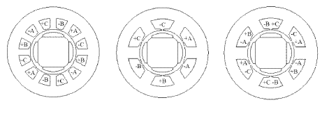
The distribution of the stator winding implies more or less interactions between the phases. In the case of a fault, we will seek to reduce its interactions to contain the fault. Figure 7.1 shows several winding configurations: with spread distribution for the left case, a concentric single layer winding in the middle and a concentric double layer winding on the right side. Research on fault tolerant solutions recommends phases be maximally separated (electric, thermal, magnetic separation). The spread distribution winding cumulates the disadvantages of proximity with the different phases‘ wires in the winding overhangs and of the important mutual inductances. The concentric double layer winding operates an efficient magnetic separation, but leaves the wires of the different phases in the same notch. The concentric single layer winding is the most efficient for the functioning safety, by eliminating any possibility of electric and thermic contact between the phases, and by operating a good magnetic separation of these phases.
Figure 7.1. Winding (from left to right): spread distribution, concentric single layer, concentric double layer
7.3. Topologies of fault tolerant converters
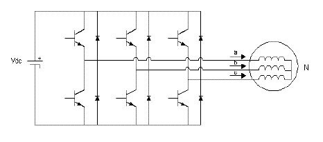
The restriction of the number of phases to three, forces the transfer of the redundancy on the converter alone. In that case, a fault leading to the loss of a phase in a three-phase motor without neutral with a conventional inverter (one bridge arm per phase as in Figure 7.2) no longer leads to the creation of rotating fields. Indeed, the current entering one of the healthy phases is inevitably the same as in the other healthy phase. There is then a creation of a pulsating field, but no possible piloting to ensure the rotation.
Figure 7.2. Conventional three-phase inverter (without redundancy)
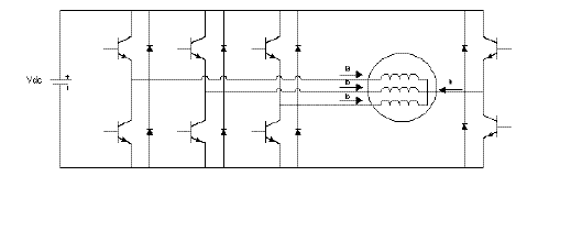
To compensate for this situation, we can offer an alternative to the current flow by adding a neutral wire, or better yet to make the phases electrically independent using a complete bridge (also called H bridge: as in Figure 7.3) for each phase [KRA 99]. This last solution helps to isolate the faulty phase and to independently pilot the healthy phases, in order to create a rotating field.
Figure 7.3. Three-phase inverter with complete bridges (with redundancy)

The disadvantage of this solution is the increase in the number of components reducing the economic interest [WEL 03a] of a machine with only three-phases, but also the reduction of the reliability inherent in any increase in the components number. It is also good to know that the switching component is the weak point of the system [SCH 03]. The appearance of the fault occurs more often in the converter than in the winding, but it can easily spread to the winding.
All these remarks favor research for other solutions, that use fewer components. A three-phase inverter (four arms in Figure 7.4) with neutral handling [BIA 03] seems to be a good compromise, provided that we implement the suitable control and that we add a component able to quickly disconnect the faulty phase [WEL 04]. These topologies will be evaluated with their controls (section 7.4.2.)
Figure 7.4.Three-phase inverter with the fourth bridge arm on neutral)
7.4. Fault tolerant controls
As presented in the previous sections, fault tolerance relies mostly on an appropriate “physical” device, with notable redundancies on the implemented components. However, it cannot rely on this material aspect alone, because the specificities of the topologies of fault tolerant converters inevitably impact on the way to ensure the piloting. It is thus essential to think differently about the control element and more precisely the control laws, in order to actually guarantee a satisfactory functioning when the faults occur.
7.4.1. Modeling synchronous machines in preparation for fault tolerant control
We can illustrate fault tolerant control with the “simple” case of the supply of a permanent magnet synchronous machine with non-salient poles (PMSM-NSP)1. The formation of the equations of the PMSM-NSP in a two-phase reference frame is as follows:
[7.2] 
where:
−Rs is the phase resistance of the stator windings;
−Ls is the cyclic stator inductance;
−p is the number of poles pairs;
−θ is the angular position of the rotor in relation to the stator;
−ψa is the Concordia (or Clarke) flux of the magnets;
−Ω is the machine rotation speed;
−vαβ is the two-phase vector of the stator voltages;
−iαβ is the two-phase vector of the stator currents;
and where P(.) is a rotation matrix defined as follows:

Later on we will introduce the electric angle θe=pθ , in order to simplify the notations.
7.4.2.Simulation of synchronous machines with fault tolerant control
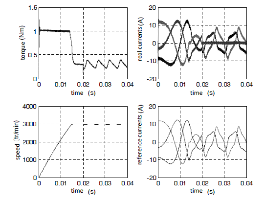
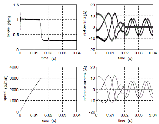
Figure 7.5. In normal functioning, evolutions of the torque, of the speed and of the three-phase reference or real currents
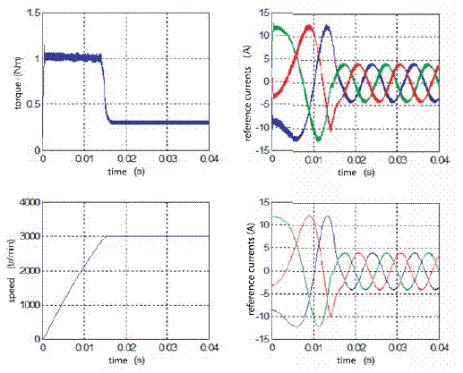
This section shows the simulation results of a low power permanent magnet synchronous machine [DOC 07]. Control is dependent on the converter topologies and will have to take into account the zero-sequence component that can appear in the faulty case. Figure 7.5 presents the torque, the speed and the real and reference currents forms during starting in normal functioning with an inverter in half-bridge. This structure does not have any fault tolerance. However, the simulation results will be used as a reference for comparison with the fault cases (in all the following figures, the fault will be set off at 0.02 seconds, after the establishment of a steady state).
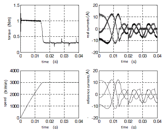
The first fault-tolerant structure considered uses an inverter with complete bridges (called H-bridges). The minimal protection consists of disconnecting the faulty phase, without changing anything about the control (see Figure 7.6). However, it is necessary to bring more energy than usual for each healthy phase, in order to preserve a constant speed. Moreover, the torque will flicker between 0.2 Nm and 0.4 Nm, for a normal value of 0.3 Nm. This simple (or even simplistic) solution leads to a deteriorated functioning mode, at the expense of the torque quality and of the component number. The current increase in steady state can be a problem in the case of extended use of the deteriorated mode.
Figure 7.6. In deteriorated mode, evolutions of the torque, of the speed and of the three-phase reference and real currents
To limit the torque it is better to modify the control depending on the fault. The homopolar current does not participate in the creation of the torque and thus a generic method consists of imposing the currents in the three-phase reference frame (a-b-c), so that the corresponding currents in the two-phase revolving reference frame (id and iq) are those at the origin of the reference torque. The regulation taking care of this task will need to have at its disposal the three-phase reference currents, according to the fault.
By using the Clarke (C3) and rotation (P3) matrices, according to the θ angle in the two-phase plane with conservation of the zero-sequence component, it is possible to determine the references of the three-phase currents for the healthy phases, as follows (example for a fault on phase A):
[7.3] ![]()
[7.4] 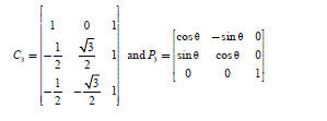
[7.5] 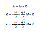
Once the fault on the phase has been detected, we proceed to the fastest possible disconnection of this phase, leading to the cancellation of ia (iα = - i0) and to the following relations:
[7.6] 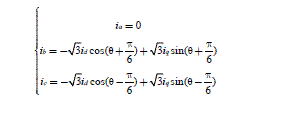
We can observe the result of this method in Figure 7.7. The developed torque has exactly the level sought after, without any ripple.
The modification in phase and amplitude of the two healthy phases leads to the expected result, but the amplitude increase for a steady state can be a problem in the case of extended use of the deteriorated mode.
In some applications, it will be better to limit the currents amplitude and to be satisfied with a slightly lower torque, in order not to risk putting another phase at fault and thus losing any piloting possibility.
Figure 7.7. In deteriorated mode, evolutions of the torque, the speed and the three-phase reference and real currents
In the particular case of a fault on a switch remaining in open circuit, it is possible, with the same complete bridges structure, to continue to pilot the three healthy switches of the H-bridge at fault (Figure 7.8).
This leads to a piloting by half-period of the phase at fault, by always seeking to find the id and iq currents, able to create the requested torque.
The piloting transitions can make low impact small torque peaks appear at each half-period.
This method leads to a reduction of the current levels at fault, thanks to the power contribution of the third phase, although it is only partial.
Figure 7.8. In deteriorated mode, evolutions of the torque, the speed and the three-phase reference or real currents
One of the justifications of the choice of a limited three-phase motor lies in the reduction of the number of power components.
It then seems appropriate to seek a fault-tolerant solution that uses fewer components than the complete bridges structure.
A conventional half-bridge inverter with neutral linked to the mass helps to obtain the same results as those obtained with the complete bridges (see Figure 7.6).
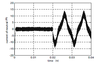
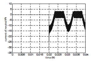
This very low cost solution, with a good reliability level, is far from being optimal, with respect to the torque quality, and generates an important neutral current in deteriorated functioning (Figure 7.9).
Figure 7.9. Appearance of a neutral current in deteriorated functioning
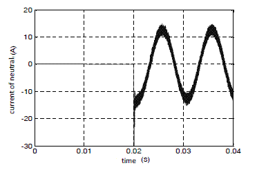
The solution to obtain a good quality torque with the use of a reduced number of switches consists of using a conventional half-bridge inverter with neutral linked to a fourth bridge arm for the neutral handling. This method helps to exactly impose the requested two-phase currents, as in the case of H bridges (Figure 7.7). This solution is always accompanied by a current increase in the healthy phases, but also by a high neutral current (Figure 7.10).
Figure 7.10. Appearance of a neutral current in deteriorated functioning
The half-bridge structure with the fourth inverter leg on neutral also leads to a half-period piloting of the faulty phase in the particular case of a fault on a switch remaining in open-circuit. The results presented in Figure 7.11 a are identical to those with complete bridges (Figure 7.8), with the appearance of a significant neutral current.
Figure 7.11.Appearance of a neutral current in deteriorated functioning
7.4.3. Predictive control
The strategies of hybrid predictive control [MOR 08] are good candidates for fault tolerant control of the power electronics converter, used for the supply of an electric machine (synchronous or asynchronous). Indeed, these strategies are based on a simple statement:
– (eventually simplified) modeling of electric machines in preparation for their control is well monitored, and helps to evaluate the evolution of the electric current in the windings for a supply at a given voltage;
– power electronics converters are essentially elements piloted by discrete (from a temporal point of view) and quantified (number of finished values) controls.
Consequently, we can plan not to calculate the control law of the converter in closed-loop, as in the case of the systems with analogical variables (i.e. belonging to the set of real numbers), but rather in “open”2 loop by a prediction of the evolution of the electric currents in the machine for each possible control value.
In the case of a three-phase inverter, we can note that piloting of the bridge arms is done by a control complemented by two switches. Thus, only one binary control ck (worth 0 or 1), called the connection function, pilots the whole of an arm. The conventional inverter is thus piloted via three binary variables and it is thus controllable by a 3D vector ϰ = (c1,c2,c3), able to take 23 = 8 distinct values.
And yet, a quick study of the association load (machine)/converter shows that the controls (0,0,0) and (1,1,1) lead to the same result: i.e. a null voltage at the terminals of each phase of the three-phase load thus supplied.
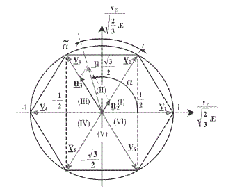
There are only seven distinct controls for one three-phase voltage inverter thus piloted: these controls result in a two-phase αβ frame (in the Clarke or Concordia sense) by the “voltage” vectors Vx (where x = 0..7) represented in Figure 7.12 (we will moreover note the equality between the vectors V0 and V7, corresponding to the controls mentioned above).
Figure 7.12. αβ “ voltage” vectors generated by a three-phase voltage inverter with three bridge arms (for a constant continuous bus voltage Vdc)
From this equation, we can simulate the evolution of the currents by doing a temporal discretization on a sufficiently fine calculation step (time interval noted Te):
[7.7] ![]()
Yet, with the predictions being based on a potentially wrong (error in the structure itself of the model) or vague (parametric uncertainties) model, a difference between reality and the predictions is inevitable.
If the control is completely in open loop, this difference will increase from one step to another, to reach unacceptable proportions for the control. Consequently, it is better to keep a closed-loop element by basing the calculation of the current prediction iαβ at the n+1 instant, not on the current prediction at the instant n, but rather on the real measured signal, highlighted with the exponent mea:
[7.8] ![]()
In addition, to make a difference between the iαβ current and a prediction, the latter will be marked with the exponent #. Of course, the EMF of the machine used in the model is an estimate of the real EMF, hence the notation êαβ.
Finally, we will note that the voltage vαβ[n,k] must successively take at each instant n all the possible values k = 0.6 (we can avoid the case 7 equivalent to 0).
At the end of all these calculations, we thus have seven prediction values of the current vector iαβ for the instant n+1. Finally, the optimal control kopt must be chosen, based on one criterion that remains to be defined.
This criterion normally consists of comparing the prediction to a reference used as set point of a currents feedback in the machine (for a torque control):
Figure 7.13. Predictions of the current vector and choice of the vector minimizing the error with the set point (⇒ voltage to apply to the load during the following Te interval)
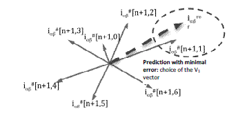
Once kopt has been determined, we apply the Vkopt vector during the time interval between the instants n and n+1. This technique is the simplest form of the predictive hybrid strategies, because it does not lead to a modulation of the “voltage” vector inside the cutting period Te. Indeed, we could describe this control as “full wave”. However, it is possible to perfect this control by doing a (balanced) composition of several predictions to exactly reach (to the model errors) the set point, provided that the set point is physically reachable in the time interval Te. It is then a response form in the sense of the automatics with discrete time.
In the framework of our study, this improvement is not really useful, even if it improves the general performances of the system, because we are mostly interested here in the principle of the predictive hybrid strategy and in its adequacy in fault tolerant control. It is thus a question of exploiting the pieces of information coming from the predictions, in order to detect the converter failures and then possibly to compensate for these failures if the physical redundancies of the system help to do it. For this, at the moment of the current acquisition at the instant n+1, it is sufficient to check that the prediction is carried out for the applied control (to the limited error). If this is not the case, a failure is detected. It is then possible to check that the obtained result gets close to another prediction (corresponding to another control value), that was kept in memory in the control element. If this is the case, it remains to compare the obtained control and the control theoretically applied to carry out a localization of the fault. Once the fault is located (completely disconnected arm, open faulty switch, closed faulty switch3), the control can then limit the control space as a function of the lost freedom degrees: a certain number of control values are indeed unreachable in the case of a fault, and it is necessary, so that this strategy is relevant, that there are redundancies in the converter, in order to guarantee a satisfactory functioning of the system (possibly in deteriorated mode).
It is obvious that a three-phase inverter with three classical bridge arms cannot meet these requirements. We will be able to consider in the following the case of the four arm inverter, ensuring a capacity to a functioning in deteriorated mode, while reasonably increasing the device complexity (from the physical point of view at the power electronics and piloting level, as well as from the software point of view with the control algorithm).
Indeed, this last point can be critical for the predictive algorithm, insofar as the number of combinations exponentially grows with the number of switches, growing all the more as we have to take a look at the additional deteriorated state of the bridge arms: the high impedance state (Z). Thus, if we discuss each of the four bridge arms of the inverter in an identical way, by considering three possible control states (“0”, “1” and “Z”), we obtain a control space at 34 = 81 available states (but some are still equivalent).
The real time calculation of the predictions for all the possible cases then becomes particularly tough. Even in the case of an installation on FPGA, that can profit from an important parallelism in the processes, the difficulty will be carried forward on the number of the logic gates consumed by such a quantity of predictions, required if another simplification is not brought (by a sharp multiplexing, or by exploitation of the symmetries in the results for the different controls, or finally by a restriction of the tested cases as a function of the objective to reach).
At first, we can take a look at the conventional healthy cases in which the fourth arm (connected to the neutral point of the star connected load) is located in the high impedance state. In that case, we find the expressions of simple voltages v1, v2 and v3 applied to the load, defined with the help of the following vector equation:
[7.10] 
where c1, c2 and c3 are the functions of binary connections (taking 0 or 1 as values) defining the state of each of the three main bridge arms of the inverter.
In the case of a load supply implementing an active state of the fourth bridge arm, we then introduce a new connection function c4 (taking 0 or 1 as values). This leads to the writing of new expressions of simple voltages gathered in the vector equation below:
[7.11] 
With equations [7.10] and [7.11], 21 distinct inverter states are described. The other cases can be considered as “deteriorated” or “faulty”, because they correspond to a setting in high impedance of at least one main arm. This case is obviously not desirable in a healthy system.
We can then focus on the prediction of the current evolution only on these cases and carry out fault detection by comparison between the prediction and a posteriori realization. This leads to three cases:
– either the prediction is carried out (with a reasonable error) and the system is healthy (no detected failure);
– or the prediction is not carried out, but the realization gets close to a case belonging to the tested set (there is a fault and it corresponds to a known state of the inverter, different from the one imposed by the control);
– or finally the prediction is not carried out and the realization does not correspond to any tested cases (there is a fault and it corresponds to an unknown state of the inverter, different from the one imposed by the control).
NOTE.– Because the last case corresponds to a high impedance situation of one of the three main arms, detection is immediate. Moreover, it is necessary to have three current sensors in the case of fault tolerant control with a four wire three-phase supply.
The optimization criterion to be applied for fault tolerant control cannot be summarized to the proposed form in equation [7.9], insofar as the system is piloted, not only in the two-phase plane with the iαβ current, but also in the homopolar direction, thanks to the increase of the number of degrees of freedom brought by the four arm inverter. Consequently, the criterion to be optimized would take the following form:
[7.12] 
where i0# is the homopolar current predicted in the load, whereas λ is a weight of this component on the criterion to be optimized.
7.4.4. Application
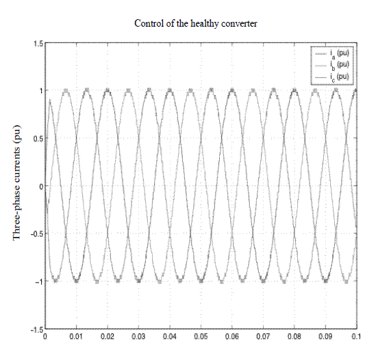
The validation tests presented below correspond to the simulation of the torque control of a synchronous machine. In Figure 7.13, we see the control behavior in the case of a healthy converter (no switches failure), whereas in Figure 7.14, we see the reaction of the controller in the case of the loss of a main bridge arm.
Figure 7.14. Reaction of the predictive hybrid control to a fault of the third inverter arm
We then note that the fourth arm becomes active, insofar as the currents injected in the two remaining phases are of a non-null sum and thus able to generate a revolving field in the machine.
Moreover, we notice that the currents amplitude is increased by maintaining the desired torque in the machine.
This is the consequence of the fact that at a given power (constant speed and torque), the same electric value must be supplied before (on three phases) and after the failure (on two phases), hence the multiplier of 3/2 applied on the currents amplitude.
Figure 7.15. Reaction of the predictive hybrid control to a failure of the third inverter arm
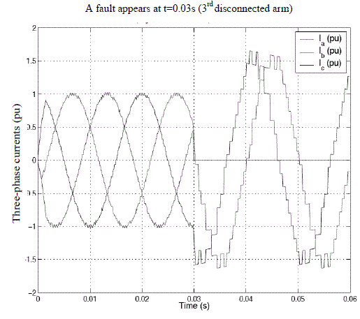
Evidently, this increase will be applied in the limit of the switches calibers and of the section of the machine windings operators: the torque set point results in a current set point (of the d-q or α,β axes) in the machine; set points that are not directly applied to the regulation, but possibly clipped, if they exceed the authorized limits.
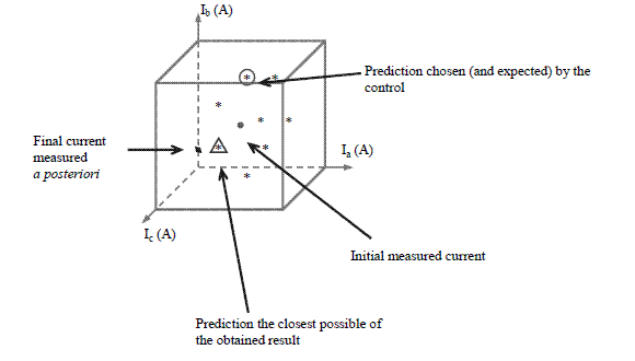
Failure detection is illustrated by the prediction cluster in Figure 7.16. When the measurement made at the end of the period gets too far from the prediction made at the beginning of it (i.e. when the error module exceeds a fixed marker4), the most likely real state (i.e. values of the connection functions) for the inverter is the one minimizing the error between the measurement and the prediction. It is then time to compare the connection function values chosen for the control in the previous sampling period and those actually applied by the system at fault. The comparison thus leads to highlighting the differences and to determine the switch(es) at fault and the corresponding fault type.
Figure 7.16. Reaction of the predictive hybrid control to a failure of the inverter third arm
7.5. Conclusion
In this chapter, we discussed the fault-tolerant control of the converter and of the means to reach the objective aimed for: i.e. to maintain a satisfying functioning (possibly in deteriorated mode) of the machine. For this, it is necessary to have a suitable control, but also a converter topology bringing the redundancies sufficient to compensate for the switch(es) at fault. In addition, we have shown that the machines can themselves be designed to limit the impact of failures such as short- circuits. Concerning the controls in themselves, we have shown several methods helping to handle failures, without any reconfiguration of its structure being necessary. Indeed, the fault tolerant control is only, with this strategy, a natural extension of the control of the healthy system, insofar as it only consists of verifying a posteriori that the prediction made at the previous sampling instant is indeed carried out at the end of the period and of possibly detecting and then locating the fault, in order to then restrict the control space to the only freedom degrees still available in the converter at fault.
NOTE.- Figure 7.15 shows the predictions in the a-b-c reference frame, but this is completely equivalent to what is obtained in the α-β-0 reference frame, where 0 corresponds to the homopolar axis.
7.6. Bibliography
[BIA 03] BIANCHI N., BOLOGNANI S., ZIGLIOTTO M., ZORDAN M., “Innovative remedial strategies for inverter faults in IPM synchronous motor drive”, IEEE Transactions on Energy Conversion, vol. 18, no. 2, p. 306-314, 2003.
[BIA 04] BIANCHI N., BOLOGNANI S., ZIGLIOTTO M., “Experiences in the design and control of PMSM drives for light traction applications”, IEEE VTS- VPPS04, Paris, 2004.
[DOC 07] DOC C., LANFRANCHI V., FRIEDRICH G., “Inverter topology comparison for remedial solution in transistor faulty case”, EPE 2007, Aalborg, Denmark, 2007.
[KES 11] KESTELYN X., SEMAIL E., “Modélisation vectorielle et commande de machines polyphasées à pôles lisses alimentées par onduleur de tension”, in J.-P. Louis (ed.), Commandes d‘actionneurs électriques synchrones et spéciaux, Hermès, forthcoming, 2011.
[KRA 99] KRAUTSTRUNK A., MUTSCHLER P., “Remedial Strategy for a Permanent Magnet Synchronous Motor Drive”, 8th European Conference on Power Electronics and Applications, Lausanne, Switzerland, 1999.
[LOC 07] LOCMENT F., BRUYERE A., SEMAIL E., KESTELYN X., BOUSCAYROL A., DUBUS J.-M., “Comparison of 3, 5 and 7 leg voltage source inverters for low voltage applications”, IEEE IEMDC07 Conference, Antalya, Turkey, 2007.
[MEC 96] MECROW B.C., JACK A.G., HAYLOCK J.A., COLES J., “Fault tolerant permanent magnet machine drives”, IEE Proceedings Electric Power Application, vol. 143, no. 6, p. 437-441, 1996.
[MOR 08] MOREL F., RÉTIF J.-M., LIN SHI X., VALENTIN C., “Permanent magnet synchronous machine hybrid torque control”, IEEE Transactions on Industrial Electronics, vol. 55, no. 2, p. 501-511, February 2008.
[PAT 07] PATIN N., MONMASSON E., LOUIS J.-P., “Fault tolerant control using a hybrid predictive strategy applied to a current controlled four-legged three phase converter”, IET Colloque on Reliability in Electromagnetic Systems, Paris, CD-ROM, May 2007.
[SCH 03] SCHWAB H., KLÖNNE A., RECK S., RAMESOHL I., “Reliability evaluation of a permanent magnet synchronous motor drive for an automotive application”, 10th European Conference on Power Electronics and Applications, Toulouse, 2003.
[WEL 03a] WELCHKO B.A., JAHNS T. M., SOONG WEN L., NAGASHIMA J.-M., “IPM synchronous machine drive response to symmetrical and asymmetrical short circuit faults”, IEEE Transactions on Energy Conversion, vol. 18, no. 2, p. 291-298, June 2003.
[WEL 03b] WELCHKO B.A., LIPO T.A., JAHNS T. M., SCHULZ S. E., “Fault tolerant three-phase ac motor drive topologies: a comparison of features, cost and limitations”, IEEE International Electric Machines and Drives Conference, Madison, USA, June 2003.
1 Chapter written by Caroline DOC, Vincent LANFRANCHI and Nicolas PATIN.
1. But generally, this can be applied to any other type of machine, as long as we have its electric model.
2. In fact, open loop functioning is restricted to a sampling period, because the predictions rely on the current measurements at the beginning of the period. The functioning is simply sampled, and as with all looped sampled systems, it functions in open loop between two sampling instants.
3. We need to specify here that the failures detected are “slow” failures not leading to a fast increase of one or several currents (short-circuit type). The fast faults are indeed preferably handled by the close control (drivers) of the switches, monitoring for example a desaturation of an IGBT in case of a sudden short-circuit (reflex action not handled by the far control).
4. To be set as a function of the degree of trust in the established model and of the precision of the parameters evaluation of this model (evidently in reasonable limits so that a failure remains detectable by discrimination between the different calculated predictions).

