Chapter 2
,Optimal Supply and Synchronous Motors Torque Control: Designs in the a-b-c Reference Frame 1
2.1. Introduction: problems of the controls in a-b-c
Chapter 1 of this book presented synchronous motors‘ modeling. The reader can find there an overview of the control problem (see sections 1.1 and 1.2, as well as [LOU 99]). This chapter utilizes the “direct models” written in the “natural reference frame”, i.e. in the “a-b-c reference frame”. It is logical to essentially consider the case of “non-salient pole” machines, particularly well adapted for representation in this reference frame. This restriction has the advantage of prioritizing “conventional controls”, adapted to “sinusoidal field distribution” machines (sections 2.2. to 2.4). This restriction also leads to powerful extensions.
Indeed, these strategies can be “extended” to – common but less conventional – controls, such as the controls of “trapezoidal field distribution” machines (or brushless DC motor), but also “advanced controls” applied to really “non- sinusoidal” machines (see sections 2.2.2, 2.2.3 and 2.3.2). We will thus conclude this chapter with a very complete presentation of original and efficient methods to optimize the supply of non-sinusoidal field distribution motors (see sections 2.5 and 2.6).
Most of this chapter will be devoted to the often critical examination of torque controls carried out by three-phase current regulations (section 2.3). We will see the limits of the classical controllers. Among the countless possible solutions, we will choose an example of an “advanced controller” (section 2.4).
2.2. Model in the a-b-c reference frame: extension of the steady state approach in transient regime
2.2.1. Case of sinusoidal field distribution machines
We start this chapter with a heuristic approach to the non-salient poles synchronous machines control. We search to extend a simple method about the steady state supply shown in Chapter 1 (section 1.4.2). In this approach, we will not use the Park transformation, but we will observe that the matrix notations help us to perform synthetic calculations. The expression of the steady state torque C1rp =Kabc ·I · sin(α) (see [1.38]) shows that the sinusoidal shape of the current leads to a torque that we can adjust in amplitude by adjusting the amplitude (I) and the phase angle (α). This legitimizes the following idea: in transient regime, the torque being described by a formula seen in Chapter 1 ([1.34], section 1.4.2), we can seek to impose a (three-phase) current defined by the expression:
[2.1] 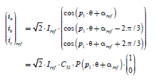
We can observe that this sinusoidal form does not impose a steady state, because the phase angle (p1 · θ+αref) can be arbitrary. This is in fact a “polar” definition of the current, with amplitude and phase (thus modulus and argument), against a “Cartesian” form. With this current form, we obtain a torque expression clearly equal to the one already described in Chapter 1, section 1.4.2.1, formulas [1.38] and [1.39]. Let us note that the index “des” indicates that it is a “desired” value:
The optimization (minimization of the current amplitude) leads to the same result as in steady state (see formula [1.40] of Chapter 1):
Therefore, we obtain the following relation ( Kabc has been defined in [1.39], Chapter 1):
[2.4] ![]()
2.2.2. Case of trapezoidal field dist ribution machines (brushless DC motor)
For the non-sinusoidal cases studied here (non-salient pole machines), the general formulas giving the converted mechanical power and the electromagnetic torque (Chapter 1, section 1.4.1, formulas [1.22] to [1.24]), deduced from the energy conservation, are applicable. Formula [1.34] (Chapter 1, section 1.4.2) only concerns the sinusoidal distribution machines. To calculate the electromagnetic torque, we will use a general formula deduced from [1.24] and [1.21] (Chapter 1, section 1.4.1):
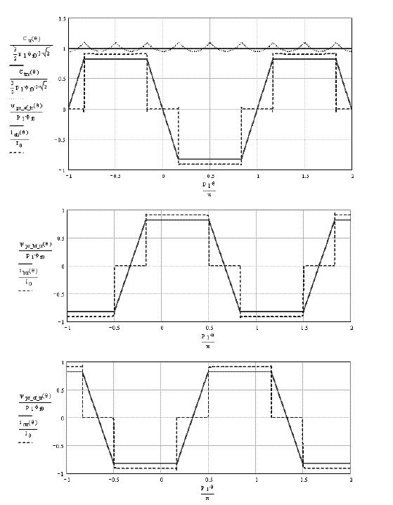
Let us consider the case of a brushless DC motor: the field distribution is trapezoidal (presented in Chapter 1, section 1.4.3.1), and the flux derivative is piecewise constant. By analogy with the case studied above (section 2.2.1), we consider supplying this machine with currents also constant at the same intervals: thus, the converted mechanical power is constant. This is technically possible in three-phase in the case δ = π/6 as seen in Figure 2.1. The current thus has a square wave form and its expression on a quarter of a period is:
[2.6] 
The Fourier series of the first phase current is:
[2.7] ![]()
Figure 2.1. Electromagnetic torque, currents and flux derivatives of the three phases of a trapezoidal field distribution machine. The square wave currents are “in phase” with the back-EMF (note: the magnitudes are reduced)
We choose to supply the machine with a current that has the same first harmonic as the current of the sinusoidal case of section 2.3.2. The first harmonic amplitude thus verifies:
The top curve of Figure 2.1 helps us to compare the torque obtained with square wave currents (see [2.6] and [2.7]), with the torque that we would obtain with a sinusoidal current with the same first harmonic. We can observe that using the sinusoidal current, the average value of the torque is almost equal to the torque created by the square wave currents. However, it is rippled.
We verify that the currents‘ sum is always equal to zero at any time, since it is a necessary property in the case of the supply by a classical three-phase inverter (Chapter 1, section 1.3.6). In fact, at any instant, one of the three phase currents is equal to zero and the other two are worth Im or -Im . The torque obtained by the square wave currents in phase with the back-EMF (back electromotive forces) verifies:
with:
[2.10] ![]()
This solution is often used in industry to supply a brushless DC motor.
2.2.3. Note on the electromagnetic torque for non-sinusoidal machines
The solution presented for the trapezoidal distribution machine is not optimal, because we do not use the back-EMF during their fluctuations (the current is then equal to zero). We will demonstrate (sections 2.5 and 2.6) that there are more efficient solutions to exactly obtain the desired torque, with no fluctuation and with a minimization of the Joule losses. This is not possible with the two solutions presented here.
We will see (section 2.6) that we can also minimize the number of harmonics introduced into the currents, in order to facilitate the implementation of the supply and of the current regulations.
2.3. Structures of torque controls designed in the a-b-c reference frame
2.3.1. Case of the sinusoidal distribution machine
Result [2.4] can be physically interpreted as follows: if a high level control unit (usually, but not necessarily the speed regulation) asks the motor to develop an electromagnetic torque of a desired value, noted Cdes , the current must have an amplitude determined from formula [2.4]. In fact, we determine “references” and Cdes is the reference torque. Therefore, it is noted Cref . It helps to calculate the
reference of the current amplitude, deduced from [2.4]. This reference then helps to determine the three-phase current references, noted (i3 _ref ) and deduced from [2.1]. The equations used to determine the references are thus:
[2.11] 
[2.12] ![]()
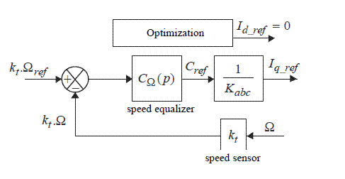
Figure 2.2 gives a determination diagram of the current reference in the case of a speed regulation. The transfer function of the speed controller is noted CΩ (P).
Figure 2.2. Block diagram for the current reference; kt is the gain of the speed sensor
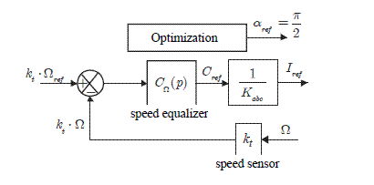
Figure 2.3 gives the schematic diagram for the determination of the three-phase current references.
Figure 2.3. Schematic diagram for the determination of the current references
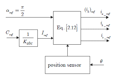
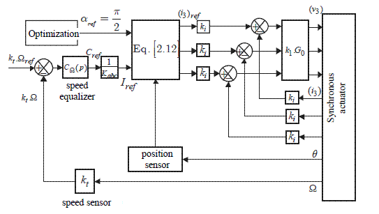
Two elements are necessary: a position sensor and a mathematical operation symbolized by the rotation matrix, carrying out formula [2.12]. This operation is usually called “self-control”; this is a synchronization of the currents on the counter electromotive forces and thus on the position. Figure 2.4 gives a schematic diagram of the current regulations.
Figure 2.4. Three-phase current regulation. ki is the gain of the currents sensors; k1 is the gain of the currents controllers; G0 is the inverter gain (see equation [1.13])
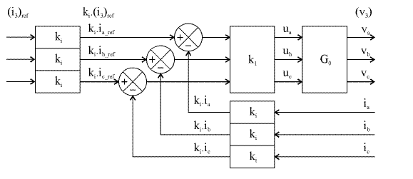
Figure 2.4 is a schematic diagram. First, there are usually only two sensors. The third one is replaced by the relation between the currents: ic = −(ia +ib). This avoids the introduction of a zero-sequence component term due to errors (measures noises, rounding errors, etc.). Then, we have represented proportional controllers, but many other variants are possible: often PI controllers, but also different types of “hysteretic regulations”. We will only discuss some forms of these questions (see section 2.4) because they are at the heart of another volume of this series [MON 11]. Figure 2.5 gives a general diagram of this control.
Figure 2.5. Global functional diagram of the speed control of the synchronous motor with a current control in the a-b-c reference frame
2.3.2. Extension to brushless DC motors (case of trapezoidal field distribution machines)
This strategy can naturally be transposed to the case of trapezoidal field distribution machines (section 2.2.2). By applying equation [2.10], we see that the amplitude of the square wave currents is given by:
with
We must then inject the currents in the three phases; these currents must be worth Im_ ref, −Im_ref or 0 . A six pulse per rotation basic encoder can then be used to impose switching instants (every 2· π/6), as seen in Figure 2.1.
2.4. Performances and criticisms of the control approach in the a-b-c reference frame
The control in the a-b-c reference frame was without a doubt the first to be implanted. This is easily explained. Indeed, it is conceptually simple and appears as a direct extension to the control of the direct current motors. It demands a minimum of components to carry out the “self-control”, and is economically appealing. But it quickly became evident that simple current regulations (such as the one that we have just presented) had limited performances. The most visible of these limits results from the presence of a static error, which is likely to be important. Indeed, the conventional linear controllers (proportional-integral) can only eliminate the static error on a constant input, whereas here the regulations seek to “follow” sinusoidal references. These references are all the more difficult to follow, as the speeds (thus the angular frequencies, since ω = p1Ω) become higher.
2.4.1. Case of a proportional control
Figure 2.6. Functional diagram of a proportional controller: phase a case
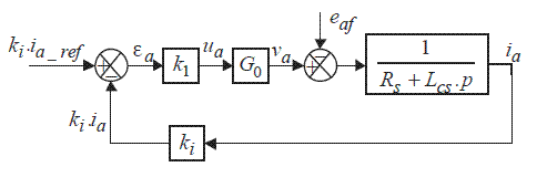
Figure 2.6 defines a very simple regulation: a proportional controller of gain k1. In the following, we will define the loop gain:
where ki is the gain of the current sensor and G0 the static converter gain. The control equation and the electrical differential equation become:
We can process this equation in transient regime or in steady state. In the latter case, it is practical to use the complex notations of Table 2.1.
Table 2.1. Notation of the variables in sinusoidal steady state in real and complex temporal forms
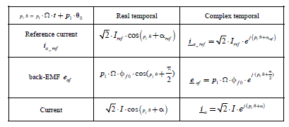
In this system, the inputs are the current references i a _ ref and the back-EMF e af (which is a disturbance). The output is the current effectively obtained, i a . Let us examine the properties of this regulation. Firstly, we can give an analytical expression of the steady state in complex notations, deduced from the forms presented in Table 2.1. We obtain [2.18]:
[2.18] 
Secondly, we examine an example of transient obtained with a “normal” gain, corresponding to a time-constant in closed-loop equal to the time-constant in open- loop (robustness arguments make this choice legitimate):
[2.19] ![]()
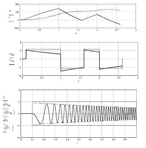
Figure 2.7. Transient example. Control in a-b-c reference frame with a proportional controller with a small gain. Note: ia (t) is given by the transient regime, but the amplitude √2.1 s given by the characteristic in steady state ([2.18])
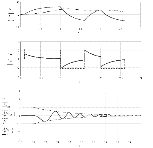
This value will give very interesting results in the controls in the d-q reference frame, examined in Chapter 3 (section 3.4.3). But in the case of this control in the a-b-c reference frame, this value is considered a “small gain”, leading to very important static errors, as showed by the results of Figure 2.7. This controller is unable to eliminate the effects created by the counter electromotive forces, such as eaf. The obtained currents are smaller than the desired references. The bottom curves show that the obtained currents‘ amplitudes are much smaller than the references‘ amplitudes. The middle curves show that the electromagnetic torque is much lower than the reference torque. And the top curves really show that the errors grow with the speed (let us recall that: ω = p1 ·Ω), as predicted by formula [2.18].
We now examine the condition of a “large gain”. We arbitrarily take a gain ten times larger than the previous one. This solution is frequently used in concrete applications, but we need to keep in mind that we currently use an analogical model, which is, in fact, an ideal case.
Figure 2.8. Transient example. Control in a-b-c reference frame with a proportional controller with a large gain
In industrial applications, the implementation is performed with digital components. We need to take into account the sampling period and the delays due to calculation times (see Chapter 5). This necessarily limits the gain amplitude (to avoid the risk of overshoots).
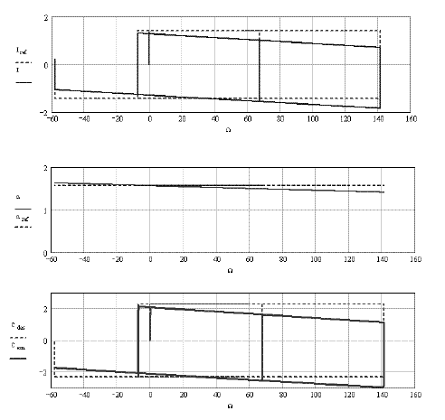
Figure 2.8 shows better results, but they remain mediocre: the torque characteristic still drops as a function of the speed. The bottom curves show that the RMS value in steady state, given by formula [2.18], is an excellent approximation of the envelope observed in the transient regime. These performances are generally illustrated by the different characteristics, functions of the speed of Figure 2.9: whether it is the RMS amplitude of the phase current (top curves) or the electromagnetic torque (bottom curves), the amplitudes are absolutely decreasing with the speed and thus move away from the reference values. Only the phase (middle curves) moves little from the desired value (αref = π/2).
Figure 2.9. Example of the current and torque characteristics, as a function of the speed during transient regimes (case of a proportional controller with a large gain)
We could look for solutions to minimize the gaps between the desired and obtained values. A very high gain is not realistic. We should consider compensating for the effect of the electromotive force, a solution that we will practice a lot with the controls in the d-q axes, where the necessary additional calculations are not prohibitive (see Chapter 3). But the point of the controls in the a-b-c reference frame is its simplicity: the necessity to determine the back-EMF value in real time in order to insert them in the control, leads to heavier calculations and the robustness is not ensured. This solution will not be studied here. Indeed, in this case, it is better to go through the d-q reference frame: the increase due to the calculation volume (because of compensation terms) is then acceptable there, with an easy “robustification”. In the a-b-c reference frame, we naturally seek simple regulations, without compensation. We can then think about integral effect controllers, a technique very popular amongst industrial applications.
2.4.2. Case of an integral and proportional (IP) current regulation
2.4.2.1. General information
The main problem is due to the pursuit of an alternative reference: there can be important static errors. We can analytically discuss the case of steady state for an IP regulator, whose principle is given by Figure 2.10.
Figure 2.10. Functional diagram of an IP controller: case of phase a

We will examine the problem of the static error in steady state on a sinusoidal input, with an IP regulation of the diagram in Figure 2.10. The equations of this control are:
[2.20] 
As we are only considering the steady state, where the angle θ verifies p1·θ = ω.t+ p1·θ0, we can associate complex amplitudes with sinusoidal temporal magnitudes, as shown in Table 2.1. The control law is defined by the amplitude and the reference current phase (see [2.11], i.e. Iref = Cref/Kabc and (αopt = π/2) and the regulation by [2.20]. The calculation in complex representation gives result [2.21]. The term τα has been defined in [2.19]:
[2.21] 
Formula [2.21] shows the existence of a static error due at the same time to:
- the presence of the back-EMF (subtractive term at the numerator);
- the ohmic drop (role of the term Rs);
- and finally, the fact that we follow a sinusoidal reference with a controller with an integrating effect (roles of the terms containing the product τy1·ω).
We see that the choice of a high loop gain ka limits the disturbance effect and the ohmic drop. But with the physical limits, we cannot choose an immensely high gain ka, and in any case the term due to the pursuit. This result shows that the control in the a-b-c reference frame with conventional controllers, cannot give good results. We will verify that fact with two examples. In these two examples, we take as a reference the electric time-constant of the phase (noted τe) and we apply results that will be demonstrated in the case of a control in the d-q reference frame (see Chapter 3, sections 3.4 and 3.5), where they will give excellent results. We thus have comparison means. With this method, we impose that the current loop with its IP controller (of the 2nd order) has two time-constants equal to τi, with:
The choice of λ (and thus of τi) imposes the gain values k1 and the time constant τy1. Indeed, the control parameters verify:
2.4.2.2. First case: with a small gain
Figure 2.11. Example of transients obtained with a control in a-b-c reference frame. IP controller with a small gain
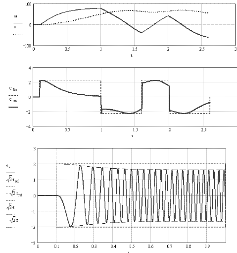
In the first example, we choose the value λ = 2 which would give very good results in the case of a control in the d-q reference frame: fast transient and elimination of the disturbance effects (such as back-EMF). In addition there are no static errors. This is not the case for this control in the a-b-c reference frame, as shown in Figure 2.11. This figure gives an example of transient response to references in the torque step. We observe (middle curves) that the torque highly decreases when the speed increases (top curves). The bottom curves give an enlargement showing that the obtained alternating currents (here ia (t)) have an envelope very well determined by the steady state formula [2.21]. We clearly see that the current‘s amplitude decreases with the speed.
Figure 2.12. The three top figures, characteristics: current (amplitude and phase) and static torque (dynamics and statics) as a function of the speed. Bottom figures, enlargement: flux derivative, reference current, current as a function of the time. Case of an IP controller with a small gain
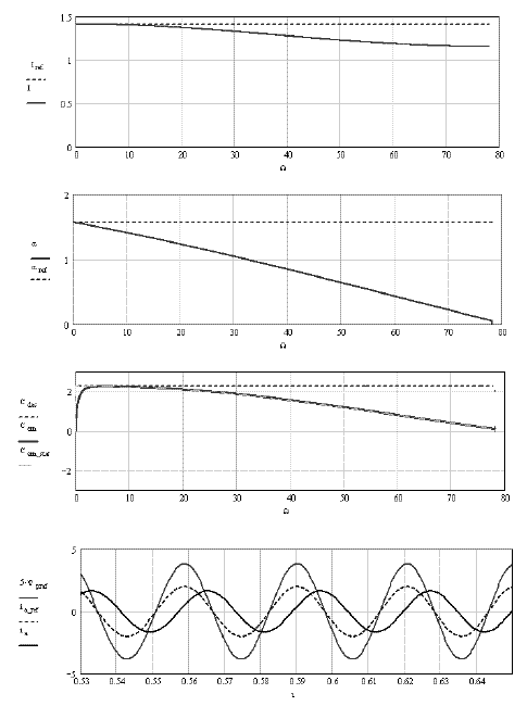
Figure 2.12 gives an example of the characteristics as a function of the speed (or the angular frequency: ω = p1·Ω), the amplitude and the current phase (see [2.21]). We observe that the amplitude and the phase decrease with the speed compared to the desired value. This results in a torque drop when the speed increases (see formula [1.38], section 1.4.2.1 of Chapter 1, i.e. C1rp = Kabc·I·sin(α)).
The bottom curve of Figure 2.12 shows the AC signals as a function of the time. We see that the current reference is well in phase with the flux derivative, but we also note that the current has a smaller amplitude and a phase angle shift that sensibly decreases. All this leads to a very important decrease in the torque. This torque control thus has very limited performances.
The third diagram in Figure 2.12 (from the top) depicts the torques. It shows that, besides the instants when there is a strong transient (as in t = 0), the static characteristic [1.38] (recalled above) is a good approximation of the determined torque in transient regime. This shows that the terms of dynamic errors are quickly softened and that the main error comes from the static terms.
2.4.2.3. Second case: with a high gain
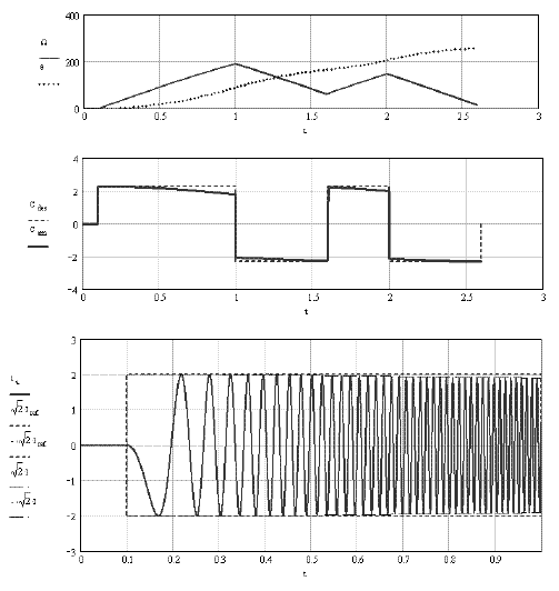
To decrease the static errors, we can work with very high gains; for example with λ = 10. Figure 2.14 gives the same magnitudes as those in Figure 2.11. It clearly appears that the large gains really have the expected effect: when the speed increases, the torque drop is limited.
These results are confirmed on the characteristics in Figure 2.13 (the same magnitudes as in Figure 2.12): when the speed increases, the amplitude and the phase angle shift decrease, but much less than in the first example. The torque has the same property: it always decreases when the speed increases, but just a little bit. However, we know that the high gains can be practically limited for the technological reasons already mentioned (in particular, the sampling period of the digital components). In any case, even reduced, the static errors still remain, because an integral effect cannot pursue a sinusoidal reference without error.
For example, the compensation can be taken into account by the higher-level loop (usually the speed regulation). But the adjustment will be done with the slow dynamics of the mechanical variables, and not with the fast dynamics of the electrical variables. Moreover, the strict model in the a-b-c reference frame is complex. And we have seen that the regulation parameters have been determined with a model adapted to the controls in the d-q reference frame, which is simpler to use for the controller design.
Figure 2.13. Three figures, characteristics: current (amplitude and phase) and static torque (dynamics and statics) as a function of the speed. Bottom curves, enlargement: flux derivative, reference current, current as a function of the time. Case of an IP controller with large gains
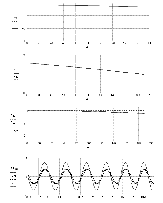
Figure 2.14. Example of transients obtained with an a-b-c control. IP controller with fast dynamics (large gains)
2.4.3. Interpretation in Park components of the IP controller designed in a-b-c
It is not particularly easy to determine the dynamic characteristics of the control in a-b-c with the a-b-c model. This is the opportunity to specify that we should not confuse “modeling in preparation of the control” with “control structure”. If it is “natural” to design an “a-b-c control” with the help of “a-b-c modeling”, we can perfectly design an a-b-c control with a d-q model (and – why not – vice versa, even if this is not really practical). We can also (as will be done in this section) model and design in a-b-c, but then interpret the result in d-q. Indeed, in the Park reference frame, the magnitudes in steady state are of the “continuous” type and it is then easier to access the dynamic performances of this type of conventional variable.
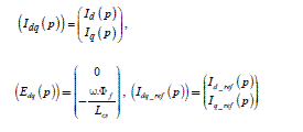
A Park transformation has been defined in Chapter 1 (section 1.5.3, formulas [1.66] and [1.67]) and the whole model of the machine in the d-q reference frame has been given by equations [1.68] to [1.71]. In the current study, we will limit ourselves to non-salient pole machines ( Ls2 = 0 thus Ld = Lq ). It is moreover necessary to have the equations giving the optimal references (see [2.1]) in the Park reference frame (it is in fact a transfer from “polar coordinates” to “Cartesian coordinates”):
The torque is written (by application of formulas [1.74] and [1.75] of Chapter 1, section 1.5.3, to the case of non-non-salient pole machines):
with:
The diagram in Figure 2.2 is immediately interpreted by the diagram in Figure 2.15.
Figure 2.15. Functional diagram for the determination of the current reference: structure in the a-b-c reference frame interpreted in d-q
Finally, it is necessary to rewrite the control equation [2.20], this time no longer in “three times single-phase”, but effectively in “three-phase”:
The Park transformation of these equations gives:
[2.28] 
We observe in the second equation of [2.28] the presence of a term describing the integration effect on sinusoidal terms. This term is a “disturbance” introducing the static error already observed in [2.21]. From the equations of the model, we can deduce the model of the current regulation state:
[2.29] 
with:
Moreover:
Let us note that this model relates to the only “fast part” of the device, i.e. to the electrical magnitudes (and to their associated values). The slow part is represented by “mechanical equations” (see [1.15] and [1.16] of Chapter 1, section 1.3.7), to which should be added the equations of the speed controller (not yet considered at this stage of the study). This model is then linear, because we can consider in it the angular frequency ω (thus the speed) as a parameter linked to the environment. In fact, we decouple the “slow” and “fast modes” and when we study the fast variables, we act as if the speed was immensely slow. In practice, we consider that ω is a constant parameter, whose value we choose for the study.
In steady state, Park components of sinusoidal magnitudes are constant and their derivatives are equal to zero. It is thus easy to analytically extract from [2.29] the expressions of the variables in steady state. Those will be noted in uppercase (for example Xd or Xq ) by analogy with continuous variables. We thus propose to write the results with complex variables defined by:
We obtain a result strictly equivalent to [2.21], but which is written with notations (in d and q) of the Park equations:
The Park approach thus gives easy access to the steady state, but also to the transient regime (see model [2.29]), which is not possible with the method in section 2.4.2. (for example with the result [2.21]).
In particular, we observe:
– that the control in the a-b-c axes is not able to “decouple” the two d and q axes;
– that the transfer function giving a Id or Iq current is of the 4th order. As we only have two control parameters, we cannot adjust the poles at will.
The transfer function can be deduced from the following equation:
where:
The characteristic equation is of the fourth degree and one expression is as follows:
We observe that analytical processing is possible. We could give a literal expression of the four poles (it would then be necessary to write square roots of complex numbers). We could use this result to perform a “poles placement”. To stay on a simple level, we have chosen the same control parameters resulting from the design in the d-q plane (Chapter 3, section 3.5). The electric part is of the 4th order. We must add mechanical variables; the dynamic model is thus of the 6th order (the state variables are id ,iq , yd , yq ,Ω, θ ).
2.4.4. Advanced controllers: example of the resonant controller
There are several solutions to force the currents to follow sinusoidal references. The most popular ones are the hysteresis controllers, discussed in specific chapters in another book in this series ([MON 11], see [NAA 11], [LEC 11], [PIE 11a]). There are other solutions (for example [NAO 11]). We will limit ourselves here to an example of a linear controller, whose “conventional integration” function is completed or replaced by “generalized integrating circuits”. Indeed, a simple integrating circuit (term in1τp) can only eliminate the errors on constant inputs. A double integrating circuit (term in 1(τ-pf ) can eliminate errors on the ramp input. A resonant controller (term in 1(p2 +ω2)) can eliminate errors on sinusoidal inputs of ω angular frequencies ([HAU 99], [PIE 11b]). Figure 2.16 gives an example of a controller deduced from the one in Figure 2.10, where the pure integrating circuit has been replaced by a resonant term. There are several variants, with terms in series or parallel, but the generalized theory of these controllers is outside the scope of this discussion. We examine only a particular example. We first observe that the loop gain is indeed infinite at the sinusoidal steady state (putp = j-ω). Moreover, the presence of a denominator k2+τ1-p gives the number of control parameters leading to a complete poles placement. Let us note that the angular frequency ω is known by the control, since the speed Ω is known (measured) and ω = p1 · Ω.
Figure 2.16. Functional diagram of a resonant-proportional controller; case of phase a

With this controller, the control equation for each phase is given by two equations (in Laplace transformation):
We use the electric equation of phase a (Chapter 1, section 1.4.1, formula [1.17]). The global transfer functions in closed-loop for phase a are then:
[2.39] 
with:
This model helps us to propose an example of parameter control. We take as a time-constant reference, the electric time-constant of a phase: τes =Lcs/Rs . We choose to impose on the closed-loop systems, three equal time-constants, τi = τes/λ, where the parameter λ has been chosen by the designer. We set out:
![]()
We identify the denominator of equation [2.39] with (1 +τi·p)3 and we obtain rules [2.41] to [2.43].
[2.41] 
[2.43] 
We observe that the time-constant τ1 and the gain k2 strongly vary with the angular frequency ω (they are even likely to become negative). This control thus raises complex theoretical and technical problems (implementation in real time). However, Figures 2.17 and 2.18 show their advantage.
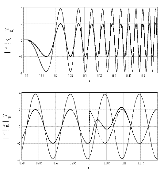
Figure 2.17 shows that the torque reference is closely followed (besides the instants of the reference discontinuity, bottom curves) and the speed fluctuation is almost linear, as expected (top curves).
Figure 2.17. Example of transients obtained with a-b-c control. Resonant-proportional controller
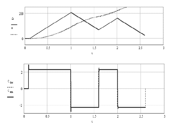
Figure 2.18 gives enlargements helping us to see the dynamic behavior of the phase current. At low speed, and thus at low frequency (top curves), the current closely follows the reference (the reference and the current are visually indistinguishable).
At high speed (bottom curves), we observe that the steady states are excellent: the current is indistinguishable from its reference, which is in phase with the flux derivative when the torque is positive, and in antiphase, when the requested torque is negative.
During a discontinuity of the requested torque (at t =1s ), we observe the current transient (reference in dashes, current in continuous curve) changing phase.
Figure 2.18. Example of the current transients with a-b-c control. Resonant-proportional controller
2.4.5. Interpretation by Park transformation of the regulation by resonant controller
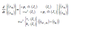
The previous analysis is done in a “three times single-phase” (or “tri-single- phase”) context. The electric equations are (apparently) simple, but the expression of the electromagnetic torque is complex (see Chapter 1, section 1.4.1., formulas [1.24] or [1.34]). To study the complete system properties, it is “friendly” to have a model in the rotating Park reference frame. We write the control equation by resonant controller under the state form of the first phase:
In fact, in three-phase, this is a 6th order system:
This equation is completed by:
where the equal to zero (O3 ) and units (I3 ) matrices are of dimensions 3x3. Park transformations are given by:
The specific dynamic model of the resonant controller is then:
These equations are completed by:
and by dynamic motor equations (see Chapter 1, for the mechanical part: section 1.3.7, equations [1.15] and [1.16], and for the electric part: section 1.5.3, equations [1.68] to [1.71]).
The dynamic model is thus of the 8th order (the state variables are
id, iq, yd, yq, zd, zq,Ω,θ).
We thus have a suitable tool to digitally simulate the system and to test its dynamic performances.
2.5. Generalization: extension of the supplies to the case of non-sinusoidal distribution machines
The controls previously described are essentially adapted to the sinusoidal field distribution machines. We have presented some extensions to a classical and quite simple non-sinusoidal case and to the trapezoidal case. But, as seen in Chapter 1 (section 1.4.3.2), more complex non-sinusoidal machines are more and more frequently used.
There is also the question of the optimization of their supply, an optimization that must take into account several criteria: minimize the torque ripples (or even eliminate them), minimize the Joule losses, facilitate the regulations implementation (it can be difficult, or even impossible to impose current harmonics of too high orders). The first question to ask is about the machine modeling, in order to do the supply optimization. In several studies, we will take into account the cogging torque.
About this subject, let us note that there are several specific strategies to eliminate this cogging torque. For example, [FAV 90] and [FAV 93] propose, thanks to an iterative approach (necessary because of the interactions between the different current harmonics), to eliminate the 6·q harmonics of the torque by determining the amplitude and the phase of the current harmonic, that will produce the same torque harmonic, but in phase opposition. In our work, we will show that a multiphase approach (n phases) is possible, and we will immediately give the application to the three-phase case.
2.5.1. Generalization of the modeling
We consider the general case of a non-salient poles machine, with non-sinusoidal distribution, a cogging torque and n phases (the phases are numbered from j = 1 to n). The model relies on the electromagnetic torque expression and on the back-EMF expressions. The total electromagnetic torque is the sum of the torque created by stator currents (containing the rotor saliency effect and the excitation effect) and of the cogging torque. We call the first, Cem _ stat (this is a function of the stator currents and of the position) and the second, Cd (this is a function of the position only):
We can write Cem_stat in the form of:
The power conversion helps us to write a relation between the torque Cem_stat and the back-EMF induced in the n phases:
We note (enf ) , the vector of n back-EMF. Each component of this vector can be represented by its development in the Fourier series, taken here in its most general case:
where:
![]()
2.5.2. A first (heuristic) approach of the solution
Correctly supplying the machine requires the choice of the ij current for each phase of the j index, so that the total electromagnetic torque is the one desired, noted Cem _1_ des. The equation to be solved is thus:
[2.54] ![]()
We propose to build a vector of the stator currents (in ) (n component vector), whose jth component has as an expression (this is an heuristic a priori choice, initially presented by [CLE 93]):
[2.55] ![]()
We find that the total electromagnetic torque can be written:
[2.56] ![]()
Then, with expression [2.55], the equation [2.54] admits a solution:
Supplying the machine with these current, produces the desired torque and compensates for the cogging torque. We will notice later on that there is an infinite number of solutions verifying the problem and that this solution is optimal when:
An extension of this method is presented in [FLI 08]. It consists of experimentally determining the term A(θ) of formula [2.56] by its Fourier series, whose coefficients are identified by a neural network.
2.5.3. First generalization: optimization of the Joule losses (without constraint on the zero-sequence component current)
Let us resume the previous problem and look for the stator currents minimizing the Joule losses and producing the total desired electromagnetic torque. The equation to be solved is then:
[2.59] ![]()
The solution must also minimize the criterion:
We have here a problem of optimization under constraint that can be solved by the Lagrange formulation. We thus write the Lagrangian:
[2.61] ![]()
where we make the multiplier λ1 appear. The optimization problem is completely described by equations [2.59] to [2.61]. It is necessary to obtain the derivative of the Lagrangian in relation to each current, and we obtain n equations of the type:
We can thus write the power created by the stator in the form of:
[2.63] ![]()
which gives an expression of the Lagrange multiplier λ1 :
We replace λ1 in [2.63] and we obtain the first optimal solution for the currents (without constraint on the zero-sequence component current):
[2.65] 
Let us write the three-phase case (n = 3 ). Then the squared back-EMF amplitude appears: ‖ef 2‖ = eaf 2 +ebf 2 +ecf 2 . We obtain the expression of optimal currents:
[2.66] 
Figure2.19. Back-EMF (top) and absolute optimal current iopt _1 (bottom, with the constant torque: 1.5 N.m) in the case of trapezoidal back-EMF
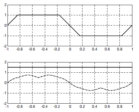
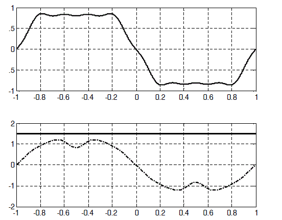
This solution ensures that the desired torque is achieved, that the Joule losses are minimized and that the cogging torque is compensated. Figures 2.19 and 2.20 illustrate these results. Figure 2.19 shows the form of the back-EMF and the optimal current in the case of a trapezoidal distribution. Figure 2.20 shows the same magnitudes in the more general case of non-sinusoidal back-EMF.
Figure 2.20. Back-EMF (top) and absolute optimal current iopt _1 (bottom, with the constant torque equal to 1.5 Nm) in the case of non-sinusoidal back-EMF
2.5.4. Application of this approach: optimization in the case where electromotive forces are sinusoidal
If the back-EMF are in the form of:
the optimal currents, deduced from [2.65], have as an expression:
which is the result given by the first heuristic approach (section 2.5.2, [2.57]), which legitimizes it.
When the back-EMF are sinusoidal, this solution does not have a zero-sequence component current, which is not necessarily the case if the back-EMF are ordinary. To cancel the zero-sequence component, we must take into account a second constraint. This is the subject of the next section.
2.5.5. Second generalization: optimization of the Joule losses with constraint (the zero-sequence component current must be equal to zero)
The equation of the second approach [2.59] and the criterion [2.60] are maintained, but we put an additional constraint: the zero-sequence component current must be equal to zero:
[2.69] 
We find a variant of this approach in [DWA 08]. The Lagrangian uses two types of multiplier, λ2 and μ2 , and is now written:
The Lagrangian derivative compared to each stator current ( j =1…n ) gives n equations:
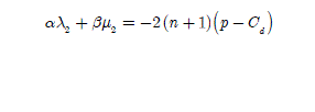
The analytical resolution of these equations helps us to give the expressions of the Lagrange multipliers:
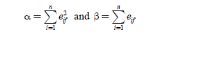
where α and β are defined by:
Note.– We have the property:
Then, we can determine several expressions of the second solution of optimal currents (with the constraint of a zero-sequence component equal to zero):
[2.77] 
Another expression can also be written:
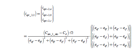
from which we deduce the most useful expressions for the three-phase machines (n = 3), corresponding to an extension of the results of [KOG 03]:
2.5.6. Geometrical interpretation of the two optimal currents
Figure 2.21. Geometrical representation of optimal currents
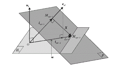
Figure 2.21 shows the geometrical properties of the optimal currents. The set of points M of coordinates equal to (in), verifying that p = Cem 1 des ·Ω = (enf)·(in) + Cd·Ω is located on the hyperplane (P) of equation (Cem 1 des − Cd) ·Ω = (enf) · (in). The vector (enf) is thus a normal vector to plane (P).
The hyperplane (P) is represented in dark gray in Figure 2.21. The point M 1 is the point at which coordinates are (iopt_,n) belonging to (P) and minimizing the norm of the vector (in) (minimization of the Joule losses without constraint on the zero-sequence component current). It is thus the closest point to O, the center of the reference frame. The vector (iopt_1n) is then proportional to (enf), so that(iopt_1n) = kopt_.(enf).
By replacing it in the equation of (P) , we obtain:
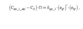
thus:
[2.81] 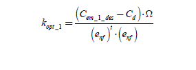
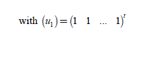
We thus find the algebraically obtained expression [2.77]. The set of points M of coordinates equal to in verifying constraint [2.69] is located on the hyperplane (H1) of the equation (u1 )t · (in) = 0 .
The vector (u1) is thus a normal vector to (H1). The hyperplane (H1) is represented in light gray in Figure 2.21.
The pointMopt 2 is the coordinates point(iopt 2n) belonging to (H1) and(P), so that the norm of (in) is minimal (with constraint on the zero-sequence component current). This is thus the closest point to O at the intersection of (H1) and(P). The vector (iopt_ 2,n) has no component according to(u1). Thus, (w) is the vector (enf) without its component according to (u1). This vector (w) is written:
[2.82] 
(iopt_2,n)is proportional to (w) so that(iopt,2,n) = Kopt_ 2·(w) . We replace it in the equation of (P) and we obtain:
Hence:
This result is similar to [2.81], the term (w) (defined by [2.82]) being substituted for (enf) . We have again the expression found algebraically (see [2.77]).
PROPERTY .– The vector X = (iopt_ 2,n) − ( iopt −1,n ) is normal to (iopt−1,n ) . We can verify it by calculating the scalar product(iopt 1,n)· X . The result can be put in the form of A/B, where:
Figures 2.22 and 2.23 give the same waveforms (back-EMF and optimal currents) as Figures 2.19 and 2.20, respectively for the trapezoidal distribution machine (Figure 2.22) and then for the non-sinusoidal distribution machine (Figure 2.23), but this time with the constraint of the zero-sequence component equal to zero current.
Figure 2.22. Waveform of the optimal current without zero-sequence component iopt _ 2 (bottom) for the trapezoidal back-EMF (top). We verify that the obtained torque is actually constant (1.5 N.m, top curve of the bottom figure)
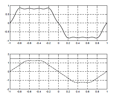
Figure 2.23. Waveform of the optimal current without zero-sequence component iopt _ 2 (bottom) for the non-sinusoidal back-EMF (top). The torque is clearly constant (1.5 N.m)
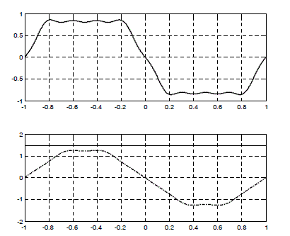
This constraint (from technical origin, related to the three wires supply) decreases the performances. Figure 2.24 represents the Joule losses obtained in three cases in the characteristic example of the trapezoidal back-EMF machine, for which we supply a comparison with the traditional square wave currents (see section 2.2.2, in particular Figure 2.1). We show that the optimal currents without constraint really minimize the Joule losses. With the constraint of the equal to zero zero-sequence component, the Joule losses increase by 4.5%. With the square wave supply, these Joule losses increase by 15%. This classical solution is thus not optimal.
Figure 2.24. Waveform of currents and torque (top) and Joule losses (bottom) in three cases: (1) with the absolute optimal current iopt _1 with zero-sequence components; (2) with the optimal current without zero-sequence component iopt _ 2 (increase of the Joule losses by 4.5%); (3) with conventional square wave currents (increase of the Joule losses by 15%)

2.6. Use of Fourier expansion to obtain optimal currents
2.6.1. Interest of the Fourier expansion (FS)
The methods carried out in the previous section are general methods leading to an absolute determination of the optimal currents, with or without constraint on the zero-sequence component current. The currents form fits synchronous machines‘ back-EMF form (see for example the curves in Chapter 1, Figure 1.9, section 1.4.3.2). Let us take an example, that of the (relatively) simple case of trapezoidal back-EMF (see Chapter 1, Figure 1.8, section 1.4.3.1). The classically implemented currents (see section 2.3.2) have apparently simple forms, since they are square wave (see Figure 2.1). But these currents are not optimal. They do not use the back- EMF during their decrease and they generate unnecessary Joule losses. Moreover, they contain high harmonics, technically difficult to realize, and maybe useless. A current regulation, generating alternating wave forms of high orders, will be difficult to carry out. We have presented the example of a “resonant controller” for the currents with only one fundamental (section 2.4.4). For a current with M harmonics, there should be a “multi-resonant controller” ([GUI 00], [ZEN 04]), that we can (for example) carry out with M resonant controllers, each one of them being tuned on a specific harmonic. This solution is very efficient, but sometimes difficult to implement.
It is also very interesting to seek to determine the optimal currents for a synchronous motor, looking to have the desired electromagnetic torque (with a minimum ripple or no ripple at all), by minimizing the Joule losses and restricting the number of harmonics in the expressions of the currents, that will be the references of current regulations. The method presented here is an extension of the one exposed in [HUN 92], [HUN 93], [HUN 94].
2.6.2. Modeling by Fourier series (with complex coefficients)
We consider the case of three-phase systems and we write the general form of Fourier series (with complex coefficients) of back-EMF and currents. For the first phase, the expressions are as follows:
For the b and c phases, we obtain the expressions of the magnitudes ebf, ib, then ecf and icby substituting firstp1-θ-2π/3, then p1·θ 2-π/3 for p1·θ . The electromagnetic torque developed by the stator currents can be written:
or:
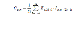
The Ca,m coefficient can be written with a convolution sum:
The torque created by the stator then has as an expression:
with
2.6.3. Properties of the results by the Fourier expansion
For m = 0 , we have C0 = 3·Ca,0 , which is the constant term of the Fourier expansion of the torque; C0 corresponds to the mean value of the torque (this is a real number). From the expression:
it appears that the useful currents to create the term C0 must have harmonics of the same order as the back-EMF. We will see later on conditions to obtain a constant torque. According to the present symmetries, the harmonics present in the back-EMF and the currents can all be of even order or all of odd order. In any case, it will give torque harmonics of a 6th order multiple.
2.6.4. First important case: the back-EMF only contains uneven order harmonics
This case appears when the back-EMF have symmetries of the type eaf (P1 · θ) = -eaf (A ·θ + π) · Then:

with m−(2k + l) = ±l,±3,±5… for each k, i.e. m = 0,±2,±4,±6… We observe that Cm is then different from zero for cos(m · 2π/3) = 1, i.e. for m = ±6·q , q = 0,1,2,3… Hence:
2.6.5. Second important case: the back-EMF only contain even order harmonics
This case appears when the back-EMF have symmetries of the type eaf (P1·θ) = −eaf (P1·θ+π). Then:
with: m−2k = ±2,±4,±6.., i.e. m = 0,±2,±4,±6.. We observe that Cm is then also different from zero for cos(m · 2π/3) = 1, i.e. for m = ±6 · q , q = 0, 1, 2, 3…
Note.– In the two previous cases, the torque has harmonics of the order 0, ±6, 12, 18…
2.6.6. General case, even and uneven order harmonics
The back-EMF contain uneven and even order harmonics. They thus do not have particular symmetries. Then:
with: m−k = ±1,±2,±3,±4., i.e. m = 0,±1,±2,±3,±4… Then, we observe that Cm is different from zero forcos(m · 2π/3) = 1, i.e. for m = ±3 · q, q = 0,1,2,3…
In that case, the torque will have harmonics of the order 0, ±3, ±6, ±9, ±12… We find again the results presented in [BOL 84].
2.6.7. Rules: to impose the torque, it is necessary to impose its different harmonics
We note as follows the limits of the harmonic orders. For the back-EMF: they contain 2.L different from zero terms; the harmonics indexes then vary from -LMax to +LMax with: LMax ≥ L , because some harmonics can be equal to zero; let us note that the constant term is equal to zero. For the currents, they contain 2·M which are different from zero terms; the harmonics indexes vary from -MMax to +MMax with MMax ≥ M .
If the back-EMF has some symmetries, the torque harmonics produced by the stator currents will be a 6th order multiple. Otherwise, the torque harmonics will be a 3rd order multiple. In general, the cogging torque is also a 6th order multiple. It is thus possible to obtain a given torque, imposed by its Fourier series (FS), if the harmonics that it contains are multiples of six or three (according to the present symmetries). However, the current must contain a minimal number of harmonics.
By choosing the number of terms of the current FS (i.e. 2·M ), the FS of the torque will then theoretically have (2·(M + L) + 1) terms, knowing that only the multiples of 3 and 6 (depending on the cases) are different from zero. Imposing the torque comes down to imposing its different harmonics. If the problem lies in the determination of the 2·M current harmonics, we would need 2· M equations, so that the problem has only one solution. But this is never the case, since the number of equations is an uneven number. There are then two situations, depending on whether there are more unknown parameters than equations and vice versa. In the first case, there is an infinity of solutions among which there is one optimal solution (minimizing the Joule losses for example). In the second case, there is no solution.
2.6.8. General approach for the optimization (heuristic demonstration in one example)
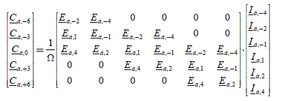
Let us consider the following case: the back-EMF complex coefficients are Ea, + 1, Ea−1, Ea, +2, Ea−2, E a, +4, Ea, −4 .
There are no symmetries in back-EMF, L = 3 and Lmax = 4.
2.6.8.1. First possibility: if we chooseM = 3
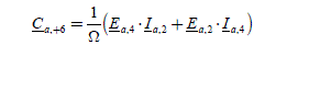
The current complex coefficients are then Ia ,1, Ia−1, Ia2, Ia ,−2, Ia ,+4, Ia ,−4, andMMax = 4 ; the torque coefficients are Ca−6, Ca−3, Ca0, Ca+3, Ca +6. There are then six unknowns to determine (coefficients of the current Fourier series) with five equations. There is thus an infinity of solutions among which there is an optimal solution. The five equations are as follows:
To obtain a constant torque of value Cem _1_des , the order of −6, −3, 3 and 6 of the torque harmonics must be equal to zero and the constant term must be the one C sought, i.e. ref for the phase a alone. We thus write: 3
[2.105] 
which we can write in the form of:
and that we synthetically note:
[2.107] 
We note that the elements of (E) are such that Ea,−k = Ea,k* , those of (C) are such as that Ca,-k = Ca,k* , which leads to Ia,-k = Ia,k* . There are three cases to consider.
2.6.8.1.1. First case: all terms of (E) are real
Then, the components of (I )and (C) are reals. The problem can be reduced to the following system:
This system admits a single solution, which is in the case of Ca,+3 = Ca,+6 = 0 :
with:
2.6.8.1.2. Second case: (E) has all its imaginary terms
Then, the components of ( I ) are also imaginary terms.
However, the components of (C) are real. The problem can be reduced to the following system:
This system admits a single solution, which is applied in the case of Ca,+3 =Ca,+6 =0:
with
2.6.8.1.3. General case: the terms of (E) are not all real, nor all imaginary
By its construction, the matrix (E) is never a square matrix, since it has an odd number of lines and an even number of columns. It is thus not reversible and the problem has an infinity of solutions. We rely on Parseval‘s equality. The optimal solution, minimizing the Joule losses at the stator of the machine, consists of finding the coefficient vector of the FS of the currents: (I) = [Ia−4 Ia−2 I a−1 Ia 1 Ia 2 Ia 4]t , its module should be minimal. The constraint to respect is always [2.107] (torque expression) and the criterion to be minimized, J, is written:
The Lagrangian is thus written:
hence:
We deduce an expression of multipliers:
The optimal solution is then given by the expression:
[2.118] 
where (C) has been defined in [2.105]. The solutions found in the first or second case (sections 2.6.8.1.1 and 2.6.8.1.2) give the same results as solution [2.118]. In the following sections (2.6.9 to 2.6.11), we will show that this expression is in fact the general solution, provided that we clearly specify the expressions of the matrix (E), corresponding to each case encountered.
2.6.8.2. Second possibility: let us look for a solution with less harmonics, for example with M = 2
The complex current coefficients are then I 1,I−1,I2,I−2 (MMax =2) and the torque coefficients are still Ca ,_6, Ca_3, Ca,0, Ca3, Ca ,6. We have four unknowns to determine (current Fourier coefficients) with five equations. This results in a hyperstatic problem, for which there is no solution. Conclusion: the minimal number of current harmonics cannot be arbitrarily chosen. There are constraints to respect.
2.6.9. General formulation of the optimization method
2.6.9.1. Objective
We propose to show how the model (E)-(I) = (C)·Ω (see [2.107]) can always
be written. Therefore, the general result [2.118] with [2.105] still remains true. For that, we need to show that we can systematically build a matrix (E) in the general case.
2.6.9.2. Discussion
The result [2.118] can be generalized, but a discussion is necessary about the harmonics orders of the current (the unknowns) and of the torque (the constraints) compared to the back-EMF harmonics (the data). The torque harmonic of a higher order depends onMMax and LMax . Theoretically, it would be worth MMax+LMax, but as it should be a multiple of 3 or 6, it is the largest multiple of 3 or 6 lower than MMax+LMax . Thus, according to the symmetries, it verifies:
or:
For example, for MMax = 23 and LMax = 9 , we obtain 30. For the case where the back-EMF have symmetries, the expression of the torque harmonics is written:
The torque harmonic of order 6 q is written with a limited number of terms.
2.6.9.3. Notations
The unknowns are the components of the current gathered in the vector: (I) = [Ia,-mMAx,…,Ia-1,Ia-1,…,Ia-1M]t. We introduce the magnitude (Ka,6.q) intervening in the convolution sum below ([2.122]) written:
[2.122] 
[K6q)t is the vector gathering the harmonics Ek of the back-EMF intervening in the convolution sum. For the currents harmonics, it is necessary to respect:
At the same time, we must take into account the constraint on the indexes of the back-EMF components, i.e. −LMax ≤ l ≤ LMax . We can finally obtain the boundaries lmin and lmax between which l varies:
hence:

2.6.9.4. Construction of the components of (K6q)t
We can consider three possible cases for the writing of (K6q)t.
Application example: we can deduce from it the first line of the matrix (E) given by C a, −6qMax·Ω = (K−6qMax)t·(I), thus:
Application example: we can deduce from this the last line of the matrix (E) given by (Ca,6qMax )·Ω = (K6qMax)t · (I , then:
The construction of the matrix (E) thus operates as follows ([2.130]):
[2.130] 
2.6.9.5. Resolution Then the equation:
Then the equation:
[2.131] 
has as a solution the expression already encountered ([2.118]) that we recall here:
[2.118] ![]()
where (C) has already been defined in [2.105]:
[2.105] 
This general result can be demonstrated by examining three cases.
2.6.9.5.1. First case: all the terms of (E) are real
In that case, the components of (I )and (C) are real. The problem can be reduced to the following system:
– the system admits a single solution if M = qMax +1;
– if M > qMax +1, there is an infinity of solutions, including the optimal solution given by [2.118];
– if M < qMax +1, there is no solution.
2.6.9.5.2. Second case: all the terms of (E) are imaginary terms.
In that case, the components of (I )are also imaginary terms, but those of (C) are real. The problem can be reduced to the following system:
with:
– the system admits a single solution if M = qMax +1;
– if M > qMax +1, there is an infinity of solutions, whose optimal solution is still given by [2.118];
– if M < qMax +1, there is no solution.
2.6.9.5.3. Application of a classical example [LEH 86]
In the example given in reference, the cogging torque is equal to zero.
This example is often quoted, because it concerns a particular case (harmonics 5 and 7) admitting an analytical solution.
The back-EMF of the first phase has as an expression:
then:
We choose to limit the current to three harmonics. It is in the form of:
then:
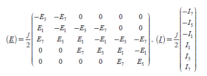
The torque harmonics presented here are Ca,−12 , Ca,-6 , Ca,0 , Ca,6 , Ca,12 and the matrix (E) and the vector (I)are written:
The equation to be solved is still [2.131], i.e.:
The three last lines give:
We then find:
with:
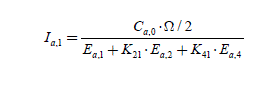
The example of harmonics 5 and 7 has a clear analytical solution:
2.6.9.5.4. General case: the terms of(E) are not all real, nor all imaginary terms
–if 2M < 2qMax +1, there is no solution;
– if 2M > 2qMax +1, there is an infinity of solutions, whose optimal solution is always given by [2.118] with [2.105]. As announced, it is the general solution.
2.6.9.6. Comments: how to optimize the harmonics?
The current thus obtained is the optimum with M harmonic components. By increasing the number of harmonics, the solution converges on the harmonic components of the optimal solution without constraint on the zero-sequence component (see section 2.5.3, formula [2.66]):
It is interesting to note that with this method, it is possible to eliminate some current harmonics. Let us assume that the machine is Y-connected, the current harmonics multiples of 3 cannot be present in the solution; which means that if the back-EMF have harmonics that are multiples of three, they should not be present in the solution. The optimal solution without zero-sequence component current then has harmonic components contained in the vector (I) . The solution has a form similar to the general solution ([2.118] with [2.105]):
The matrix(E‘)is obtained as the matrix (E) without the harmonics multiple of 3. If we increase the number of harmonics of this solution, it converges on the harmonic components of the optimal solution without constraint on the zero- sequence component (equal to zero) (see sections 2.5.5 and 2.5.6):
2.6.10. An important example: the sinusoidal field distribution machine
Let us consider the case of a sinusoidal field distribution machine. We have:
then:
i.e.:
hence:
We then find the result of section 2.2.1.
2.6.11. Application: obtaining a constant torque
2.6.11.1. Discussion
In this section, the cogging torque is neglected. The constant FS term of the torque is written:
[2.153] 
To obtain a constant torque, it is necessary to impose this term and cancel all torque harmonics of multiples of 6 or 3, depending on whether or not there are symmetries. The currents and back-EMF harmonics of the same order contribute to the term Ca 0. To obtain a constant torque, it is thus sufficient to have MMax = LMax.
QUESTIONS.- Under which conditions can sinusoidal currents create a constant torque? Under which conditions can currents with harmonics of order −(2k +1), − (2kr − l),…,−3, −1, 1, 3, … (2k − l), (2K +1) create a constant torque?
A sinusoidal current has two harmonics in the order of ±1 that will create 0 torque harmonics with the back-EMF fundamental and torque harmonics of the order of ±3q or ±6q, if the back-EMF contain harmonics in the order of ±3g±l or ±6q±l (respectively).
The two unknowns are the current harmonics, and the equations to be respected are Ca0 = Cref/3 on the one hand, and all the torque harmonics produced by the interaction of the current fundamental and the back-EMF harmonics in the orders of ±3 · g ± 1 or ± 6 ± q ± 1, i.e.: Ca ±3 =0 or Ca ±6 = 0 on the other hand. As it is not possible to impose more than one constraint with only two current constraints, the only possible solutions are those for which the back-EMF do not have harmonics in the order of ±3·q±l (no symmetries in the back-EMF) or ±6·q± 1 (symmetries in the back-EMF).
2.6.11.2. Example
A machine with the harmonics −9,−7, −5, −3, −1, 1, 3, 5, 7, 9 in its back-EMF will not be able to produce a constant torque with a pure sinusoidal current, because there will be creation of a torque harmonic in the order of 6 (±6 = ± (7 − 1) = ±(5 +1)). However, it will be possible if the back-EMF contain only harmonics in the order of multiples of three.
Let us extend the reasoning: currents with harmonics in the order of -3,-1,1 and 3 (i.e. four unknowns) will be able to give a constant torque, if the equations to be respected concern the torque harmonics in the order of -3, 0 and 3 (no symmetries in the back-EMF) or -6, 0 and 6 (symmetries in the back-EMF). In those two cases, there are only three equations to respect. We will not be able to cancel the torque harmonics in the order of ±3 · q for q ≥ 2 or ±6 · q for q ≥ 2 ; they must be naturally equal to zero. This imposes that the back-EMF does not contain harmonics in the order of ±(3q±l) and ±(3q±3) for q ≥ 2 or ±(6q±l) and ±(6q±3) for q ≥ 2 . For example, the same machine will not be able to produce a constant torque with a current with a fundamental and a 3 harmonic, because there would be the presence of 12th order torque harmonics (±12 = ±(9 + 3)).
In the general case, if the currents have harmonics in the order of −(2k l),−(2k−l),…,−3 ,−1, 1, 3,...(2k−l),(2k + l) (i.e. 2k unknowns), they will be able to give a constant torque, if the equations to be respected concern the torque harmonics in the order of −6(k−ϊ),−6(k−2),..., −12, −6, 0, 6, 12,..., 6(k−ϊ) (symmetries in the back-EMF), i.e. 2k −1 equations. We will not be able to cancel the torque harmonics in the order of ±6q for q ≥ k; they must naturally be equal to zero. This imposes that the back-EMF must not contain harmonics in the order of ± (6q ± l), ± (6q ± 3),…, ± (6q ± (2k +1)), for q ≥ k. If the back-EMF does not have symmetries, it must not contain harmonics in the order of ±(3q±l),±(3q±3),…,±(3q±(2k + 1)),q ≥k.
2.6.12. Some results
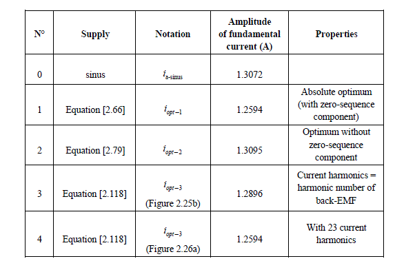
Figure 2.25a recalls the waveforms (flux and counter electromotive forces) of the machine presented in Chapter 1 (section 1.4.3, Figures 1.9 and 1.10, with the parameters quoted in appendix section 1.7.1). Figure 2.25b presents the currents obtained with the different methods exposed in the previous sections (Table 2.2 explains the captions). It is striking that, despite the fact the currents‘ forms are different, they produce the same constant desired torque. Let us note here that with the purely sinusoidal current supply, the torque fluctuates with an amplitude △Cem = 0.093 Nm (i.e. 6.2% of the reference torque). This fluctuation is important and is not acceptable for many applications where we demand much better performances.
Figure 2.25a. Flux (top) and counter electromotive forces (bottom) of the machine studied
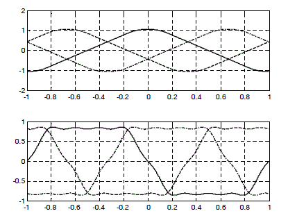
Figure 2.25b. Top curve: obtained torques. Bottom curves: optimal torques, iopt _1 (absolute optimal with zero-sequence component), iopt _ 2 (optimal without homoplar), iopt _ 3 (the latter obtained with a number of harmonics identical to that of the back-EMF). Table 2.2 clarifies the legends
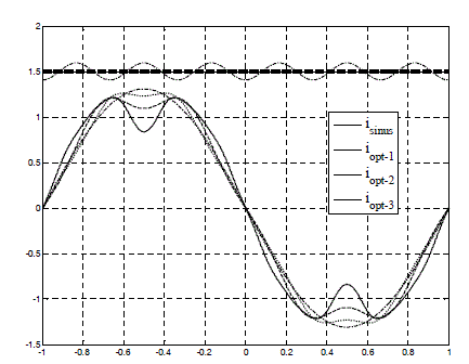
Figure 2.25c. Joule losses related to each method exposed in Figure 2.25b. The band no. 0 corresponds to the sinusoidal case; the band no. 1 presents the losses with the absolute optimal current (with zero-sequence component); the band no. 2 corresponds to the optimal with constraints (equal to zero zero-sequence component current, losses raised by 4%); the band no. 3 shows the losses with the method where current harmonics are in limited number (losses raised by 2%)
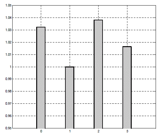
Figure 2.25c compares the Joule losses obtained by different methods. By observing this figure, we see that solution 1 (no constraint on the zero-sequence component) is clearly the absolute optimal. Other methods also give a constant torque, but they are not optimized on the Joule losses level in the machine. We have seen that if the number of harmonics taken in the method with FS tends towards infinity, then this approach converges on the optimal solution.
Figure 2.26a shows the result given by the Fourier series method, in the case where current harmonics are of order 1, 3, 5, 7, 11, 13, 15, 17, 19, 21, 23. We observe that the two currents iopt−1 and iopt−3 are also superimposed. With Figure 2.26b, we can conclude that the two solutions are optimal.
Figure 2.26a. Torques (top curves) and stator currents (bottom curves) obtained by the different calculation methods to obtain a constant torque by minimizing the Joule losses (for legends, see Table 2.1). Let us note that the current iopt-3 is obtained with current harmonics taken up to the 23rd order, which eliminates the torque harmonics up to the 30th order. The solution iopt _1 (absolute optimum with zero-sequence component) and solution iopt _ 3 are superimposed
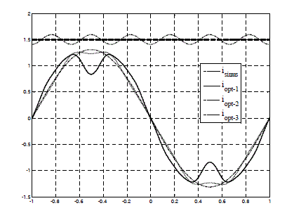
Figure 2.26b. Joule losses related to each method exposed in Figure 2.25d
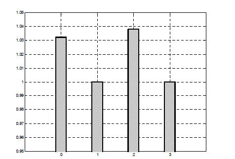
Table 2.2. Comparison of the different methods
2.7. Conclusion
In the first sections (sections 2.2 and 2.3), we presented the torque and current controls of classic synchronous motors (with sinusoidal or trapezoidal field distribution), when they are designed in the three-phase a-b-c reference frame, which is natural for non-salient pole machines. Section 2.4 gave examples of classical controllers and we saw that the design and implementation simplicity can be paid for by mediocre performances for the tracking of alternating references. There are “advanced” solutions for the controllers: we gave one example (but this theme is more the subject of [MON 11]). The controls in the “Park reference frame” or the d-q reference frame are another solution to this question, and they will be examined in Chapter 3.
In sections 2.5 and 2.6, we extended the study by exposing very complete general methods to define the optimal current references for “less classic” synchronous motors with non-sinusoidal back-EMF (more complex than the trapezoidal back-EMF). In section 2.5, we saw that we can systematically determine the absolute optimum (currents which generally use a zero-sequence component) and optimums with constraint on the zero-sequence component current (equal to zero). These currents lead to the desired torque, by compensating for the cogging torque. As the presence of high harmonics in the feed current can have technological difficulties (for the implementation), section 2.6 has been devoted to an optimization with or without constraints on the harmonics. Once again, a general resolution method has been achieved, finding again all the known results and providing new ones.
2.8. Appendices
2.8.1. Digital parameters values
The examples of the back-EMF and of the currents presented in this chapter concern motors whose parameters have been defined in appendix section 1.8.1. of Chapter 1.
2.8.2. Nomenclature and notations
Chapter 1 defined a large number of notations (section 1.8.2). Here we will only give those specific to this chapter.
2.8.2.1. Regulations
We give the notations related to the regulation parameters and variables:
- of speed: speed controller, CΩ (p) ;
- of current:
- three-phase feed current references, current parameters in sinusoidal: Iref, αre/ ; in dynamic regime: iref a (example of the first phase),
- torque references Cdes, Cem_1_des, Cem_1_des,
- current and voltage plateaus values (trapezoidal case): Im,Em,
- current controller: gain k1 ; loop gain ka ; time-constant of the integrating circuit τy1 ; state variable of the integrating circuit y; angular frequency of a resonant controller ω,
- controller adjustments, control parameter λ , reference time-constant: |τref.
2.8.2.2. Current optimization with non-sinusoidal back-EMF
We give notations related to the variables for the currents optimization with non- sinusoidal back-EMF:
- current vectors: with n phases, (in) ; in three-phase, (i3) ;
- torques: total electromagnetic torque, Cem ((i3),θ) ; torque created by the stator only, Cem stat ((i3),θ) ; cogging torque, Cd (θ) ; references, Cem_1_des ;
- optimal currents, without constraints on the zero-sequence component (iopt_1, n)(n: phases number) or with constraint on the zero-sequence component equal to zero (iopt 2 n) ; in three-phase (iopt 2 3).
2.8.2.3. Current optimization with non-sinusoidal back-EMF by FS
We give the notations related to the variables for the currents optimization with non-sinusoidal back-EMF by the FS method:
- mth order harmonics (phase a as an example) for the back-EMF: Eam ; for the currents: I_am; for the torques: Ca m (note: average torque, Ca 0);
- harmonics orders: the back-EMF contain 2 L terms different from zero; the indexes harmonics vary from -LMax to +LMax, with: LMax ≥ L . The currents contain 2·M different from zero terns; the harmonics indexes vary from −MMax to +MMax, withMMαx ≥M ;
- k or l: integers intervening in the convolution sums helping the electromagnetic torque calculation;
- q: integer helping us to perform the electromagnetic torque harmonics indexing;
- (E), (I), (C): vectors of the complex coefficients containing the complex amplitudes of the harmonics (notations for the optimization).
2.9. Bibliography
The bibliography in Chapter 1 (section 1.9) gave the first references list. We only give further references here.
[BOL 84] BOLTON H. R., ASHEN R., “Influence of motor design and feed-current waveform on torque ripple in brushless DC drives”, IEE Proceedings. Part A. Physical Science, Measurements and Instrumentation Management, vol. 131, no. 3, 1984.
[CLE 93] CLENET S., LEFEVRE Y., Sadowski N., Astier S., LAJOIE-MAZENC M., “Compensation of permanent magnet motors torque ripple by means of current supply waveshapes control determined by finite element method”, IEEE Transactions on Magnetics, vol. 29, no. 2, 1993.
[DWA 08] DWARI S., L. PARSA, “An optimal control technique for multiphase pm machine under open-circuit faults”, IEEE Transaction on Industrial Electronics, vol. 55, no. 5, 2008.
[FAV 90] FAVRE E., JUFER M., “Cogging torque suppression by a current control”, Proceeding of International Conference on Electric Machines, Cambridge, MA, United States, p. 601-606, August 1990.
[FAV 93] FAVRE E., CARDOLETTI L., JUFER M., “Permanent-magnet synchronous motors: a comprehensive approach to cogging torque suppression”, IEEE Trans. Ind. Applicat., vol. 29, p. 1141-1149, November-December, 1993.
[FLI 08] FLIELLER D., GRESSIER J., STURTZER G., OULD ABDESLAM D., WIRA P., “Optimal currents based on adalines to control a permanent magnet synchronous machine”, 34th Annual Conference of IEEE, (IECON 2008), p . 2702-2707, 10-13 November 2008.
[GRE 04] GRENIER D., STURTZER G., FLIELLER D., LOIUS J.-P., “Extension de la transformation de Park aux moteurs synchrones à distribution de champ non sinusoïdales”, in Louis J.-P (ed.), Modèles pour la commande des actionneurs électriques, Hermès, Paris, 2004.
[GUI 00] GUILLAUD X., HAUTIER J.-P., Wulve K. M., Crespi F., “Multiresonant corrector for active filter”, Industry Applications Conference, 2000, Conference Record of the 2000 IEEE, vol. 4, p. 2151-2155, 8-12 October 2000.
[HAU 99] HAUTIER J.-P., GUILLAUD X., Vandecasteele F., Wulveryck M., “Contrôle de grandeurs alternatives par correcteur résonnant”, Revue Internationale de Génie Electrique, vol. 2, no. 2, p. 163-183, 1999.
[HUN 92] HUNG J.Y., DING Z., “Minimization of torque ripple in permanent magnet motors-a closed form solution”, International Conference on Industrial Electronics, Control, Instrumentation, and Automation, vol. 1, p. 459-463, 1992.
[HUN 93] HUNG J. Y., DING Z., “Design of currents to reduce torque ripple in brushless permanent magnet motors”, IEEE Proceedings-B, vol. 140, no. 4, 1993.
[HUN 94] HUNG J. Y., “Design of the most efficient excitation for a class of electric motor”, IEEE Transactions on Circuits and Systems-I: Fundamental Theory and Applications, vol. 41, no. 4, 1994.
[KOG 03] KOGURE H., Shinohara K., Nonaka A., “Magnet configurations and current control for high torque to current ratio in interior permanent magnet synchronous motors”, IEEE International on Electric Machines and Drives Conference, vol. 1, p. 353-259, 2003.
[LAJ 95] LAJOIE-MAZENC M., VIAROUGE P., “Alimentation des Machines synchrones”, electrical engineering treatise, D3630 and D 3631, Techniques de l‘Ingénieur, 1991.
[LEC 11] LE CLAIRE J.-C., “Current control using self-oscillating current controllers”, in Monmasson E. (ed.), Power Electronic Converters: PWM Strategies and Current Control Techniques, ISTE, London and John Wiley & Sons, New York, 2011.
[LOU 99] LOIUS J.-P, BERGMANN C., “Commande Numérique des Machines synchrones”, Techniques de l‘Ingénieur, Paris, D 3644, May 1999.
[MAR 92] MARCHAND C., RAZEK A., “Electromagnetic modeling to optimize low speed and position control in servo motor”, International Workshop on Electric and Magnetic Fields from Numerical Models to Indutrial Applications, Liège, Belgium 28-30 September 1992.
[MON 11] MONMASSON E. (ed.), Power Electronic Converters: PWM Strategies and Current Control Techniques, ISTE, London and John Wiley & Sons, New York, 2011.
[NAA 11] NAASSANI A.-A., NAOUAR W., MONMASSON E, SLAMA-BELKHODJA I., “Sliding mode current control for a synchronous motor”, in Monmasson E. (ed.), Power Electronic Converters: PWM Strategies and Current Control Techniques, ISTE, London and John Wiley & Sons, New York, 2011.
[NAO 11] NAOUAR W., MONMASSON E., SLAMA-BELKHODJA I., NAASSANI A.A., “Predictive current control for a synchronous motor”, in Monmasson E. (ed.), Power Electronic Converters: PWM Strategies and Current Control Techniques, ISTE, London and John Wiley & Sons, New York, 2011.
[PIE 11a] PIERFEDERICIi I. S., MEIBODY-TABAR F., “Hybrid current controller with large bandwidth and fixed switching frequency”, in Monmasson E. (ed.), Power Electronic Converters: PWM Strategies and Current Control Techniques, ISTE, London and John Wiley & Sons, New York, 2011.
[PIE 11b] PIERQUIN J., DAVIGNY A., ROBYNS B., “Current and voltage control strategies using resonant correctors: examples of fixed-frequency applications”, in Monmasson E. (ed.), Power Electronic Converters: PWM Strategies and Current Control Techniques, ISTE, London and John Wiley & Sons, New York, 2011.
[STU 00] STURTZER G., FLIELLER D., LOIUS J.-P., GABSI M., “Extension de la transformation de Park aux moteurs synchrones à entrefer variable non sinusoïdaux et saturés”, RIGE, vol. 3, no. 3, p. 313-345, 2000.
[STU 02] STURZER G., FLIELLER D., LOIUS J.-P., “Extension of the Park‘s transformation applied to non-sinusoidal saturated synchronous motors” EPE Journal, vol. 12, no. 3, p. 16-20, August 2002.
[STU 03] STURZER G., FLIELLER D., LOIUS J.-P., “Mathematical and experimental method to obtain the inverse modeling of non-sinusoidal and saturated synchronous reluctance motors”, IEEE Transactions on Energy Conversion, vol. 18, no. 4, p 494-500, December 2003.
1 Chapter written by Damien FLIELLER, Jean-Paul LOIUS, Guy STURTZER and Ngac Ky NGUYEN.


