2
Security of Wireless Systems
2.1 Overview
This chapter describes the security architecture of the most relevant modern wireless and mobile systems, with the main weight on 3GPP and IEEE 802 networks. The security aspects of satellite systems, special systems represented by TETRA and broadcast networks are discussed, as well as local wireless connectivity. Practical examples are presented that identify potential security threats and also methods for protecting confidentiality of the mobile communications. The examples include user actions like calls and messaging, as well as operator‐related functions like subscription management. This chapter also gives an overview of security aspects in the interoperability and interworking of the networks, including 3GPP networks, non‐3GPP networks and related Wi‐Fi Offload.
2.1.1 Overall Security Considerations in the Mobile Environment
The data services of current mobile communications networks are increasingly based on packet connectivity. This has greatly enhanced the efficiency of the cellular connections, providing superior user experiences compared to the preceding solutions that were based on circuit‐switched techniques. At the same time, as the current mobile services are comparable to the principles of the Internet, so have similar types of security threats increased. It can be generalized that the security breaches familiar from the public Internet are in many ways relevant in mobile communications, and thus require similar protection mechanisms. This applies to both ‘traditional’ feature mobile phone equipment and advanced smart devices. Furthermore, not only is data transmission under threat but also the services related to voice communications may be vulnerable.
Some examples of the security threats of commercial mobile communications may be related to the economical exploitation of the user credentials (some concrete cases being the stealing of credit card information or other type of company secrets) or ‘virtual vandalism’ (as can be the case, e.g., in the interfering of calls). Apart from the threats related to end‐user and business communications, there also exist potential threats in special environments which may jeopardize the safety of, e.g., governments and defence forces. An example is an attacker who may want to seek strategic level information from the mobile communications, either in real time or by post‐processing the stored data that could be obtained via the publicly exposed but secured channels, or by trying to enter the internal network infrastructure. There may also be intentions to paralyze mobile networks and related services in order to block completely the legitimate communications.
Whatever the threat, its impact needs to be minimized via preparation from the known and expected threats and by setting up respective protection mechanisms prior to the moment when the concrete attacks take place. This is a joint effort which can ideally be done in cooperation between operators, equipment manufacturers and end‐users.
As the mobile communications networks develop along with the new generations, the protection mechanisms also improve. As is the case with any other form of telecommunications, the latest mobile system generations may contain weaknesses that are exposed as a result of the overall development of electronics and novelty HW and SW attack types. Not only are the networks and user equipment under threats but today’s environment, especially services and applications that are used on top of the protocol layers, brings along previously unknown challenges. One example is the increasingly utilized cloud storage that can be accessed via mobile communications networks. Typically deployed as a separate component from the mobile network infrastructure, the contents of the cloud server may be vulnerable against unauthorized access regardless of the security level of the mobile systems. Equally, the increasingly popular smart devices equipped with applications expose security vulnerabilities familiar from the public Internet, i.e., the malicious attacker can aim to access the user data, copy, modify and destroy the contents and manage the devices via viruses.
2.1.2 Developing Security Threats
One of the highly concrete security threats of today and in the near future is related to the IoT, which also includes M2M communications. A multitude of devices that are connected to Internet either wirelessly or via a wired manner, like printers and video surveillance cameras, audio systems or even light bulbs, may open unknown back doors right into the otherwise well‐protected environment. One such security threat is a simple default password of the device manufacturer that the user does not change. This is especially problematic for devices that are able to jeopardize the personal health of the user, such as Internet‐connected self‐driving cars [8].
Whether it is about servers, laptops or simple IoT devices, the ways for ensuring adequate shielding against the most obvious attack attempts include changing the default passwords before utilization of the equipment, as well as monitoring the traffic flows of systems, updating virus protection, maintaining the latest and protected firewall settings, using common sense in the installing of new applications, and applying any other reasonable shielding principles familiar from the public Internet. For highly confidential communications, a feasible way to ensure protection is to use a point‐to‐point scrambling solution in the application layer. Furthermore, when storing confidential information outside of the local systems, like into clouds, a user‐managed data‐scrambling solution provides extra protection.
As for the fixed and mobile network operators and service providers, monitoring of the fraudulent attempts has been a daily routine for a long time, and typically there is also at least some sort of basic virus protection mechanism applied. The obviously suspicious behaviour, such as intentions to modify user profiles as a part of hijacked end‐user equipment for scam emailing, can be tracked from the network side but that alone cannot prevent security breaches without the active role of the end‐user.
The importance of the IoT, as well as the increasing amount of IoT security threats, can be interpreted from the statistics presented by Verizon in Refs. [9,12]. According to the data, the year‐to‐year growth of global IoT devices can be estimated to present a steady 28% figure during 2015–2020. According to this source, the total number of IoT devices may be around 5.4 billion by 2020 while it was about 1.4 billion in 2014.
Regardless of the technology and level of the radio interface protection, the path of the mobile system’s radio network represents similar security principles as is the case for fixed telephony networks. The telecommunications networks are by default closed environments and thus protected from external attacks. The modern networks are based on digital transmission and fibre optics which means that it is challenging to access them by external parties for unauthorized eavesdropping. Nevertheless, if the unauthorized party does have access to the communications, e.g., via an unprotected radio link of the transport network, there is not much to be done for detecting or preventing such attempts, apart from the deployment of additional encryption devices for those links.
Not only is eavesdropping a threat but also the intentional – or unintentional – damaging of the network may be a severe issue. As a result, part of the communications network service may break down, including emergency call attempts. Public news stories have reported occasionally about service level degradation of fixed or mobile communications networks, which can result in regional service blackout. This can happen when strategically important fibre optics cables are damaged, typically due to construction works in the area. The proper redundancy with clearly physically separated cabling of the transport network is thus one of the important preventive protection methods of the infrastructure provider to minimize the negative impacts of such incidences.
Back in the 1990s, the mobile networks were isolated from the public data networks, and only circuit‐switched data methods were used for accessing early Internet‐type of services. The General Packet Radio Service (GPRS) that was deployed at the beginning of the 2000s opened packet‐switched channels into the Internet which, in turn, exposed a completely new world of potential security threats for the end‐users as well as for the operators. One example of such an issue is the attempt to overload the internal network by repeatedly sending Packet Data Protocol (PDP) context activation requests from the external network to either real or imaginary GPRS users. Such attempts can trigger a big amount of signalling by the Home Location Register (HLR) and Visitor Location Register (VLR) of the GSM network as part of the procedure for resolving the location of the receiving party. These messages can overload the signalling resources of the GPRS, and as the GSM user registers are common for both data and voice users, the voice traffic of the GSM network may also be impacted. This type of relatively simple DoS attack can be prevented in the border of the GPRS network at the GPRS Gateway Support Node (GGSN) element by using additional traffic analysis and blocking procedures. Thus, the early deployment of GPRS has resulted in the introduction of such firewall‐type of protection mechanisms familiar from the public Internet. In fact, operators tend to avoid the utilization of the option to activate the PDP context via the network due to the aforementioned reason, so the user device typically makes the opening – which can also happen after a push message in a form of a short message from the network side.
Since then the utilization of the packet data has increased exponentially as a result of considerably higher data rates and lower latency of the mobile communications networks, which makes the mobile data communications comparable or even more appealing for Internet traffic compared to fixed Internet lines. As a result, many more mobile applications have been developed for all kinds of purposes. One of the main drivers for future data utilization is related to the growth of smartphone penetration. As an example, Informa estimated that during 2010, 65% of global mobile data traffic was generated by the 13% of mobile subscribers who used smartphones, with the average traffic per user of 85 MB per month. As can be seen in the ITU statistics presented in Figure 2.1, the mobile broadband traffic has been growing exponentially, as interpreted from Ref. [60,36].
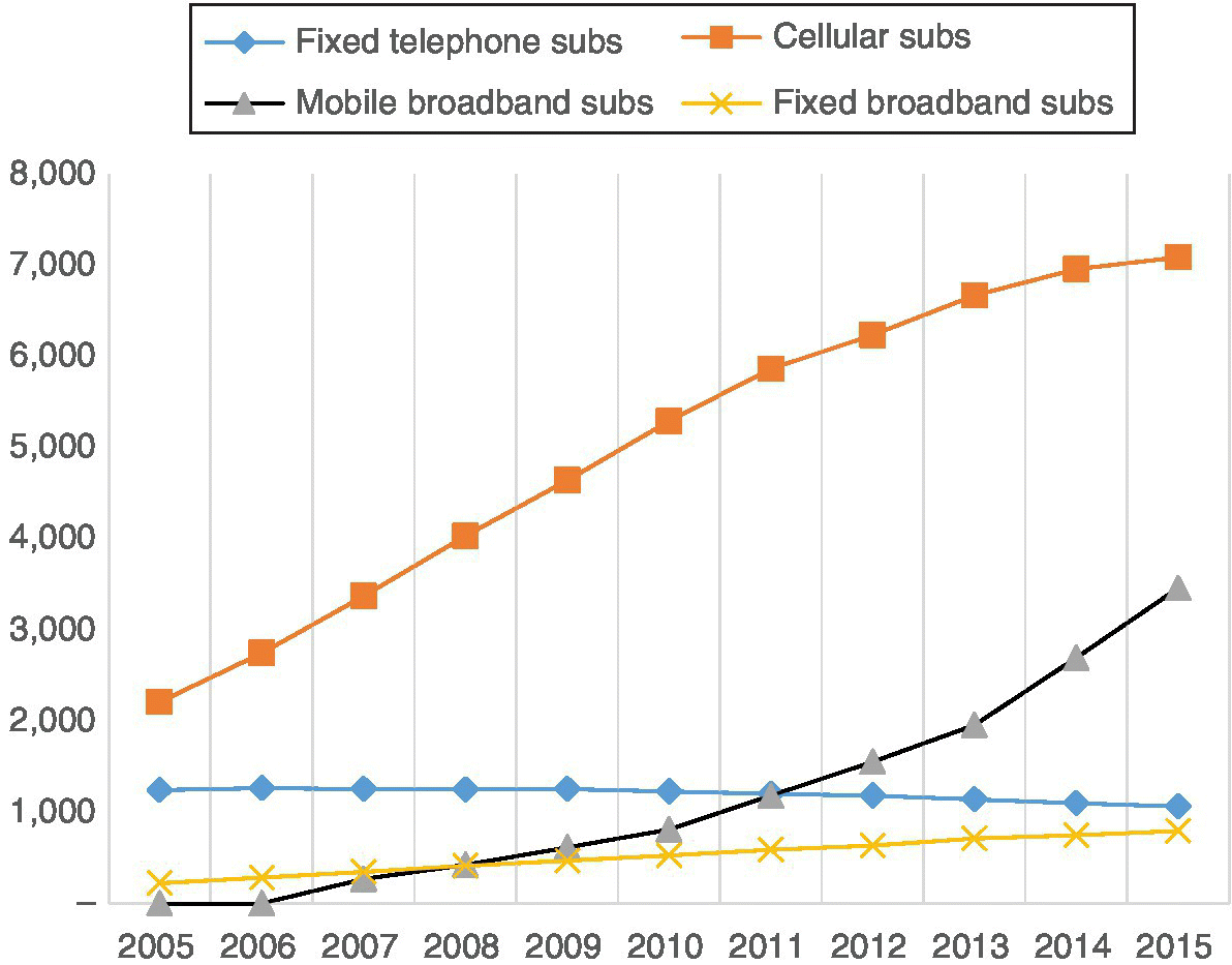
Figure 2.1 The statistics of data consumption of mobile laptop and smartphone users
In order to cope with the increasing mobile data consumption, the LTE and LTE‐A networks will provide highly needed capacity and higher data rates for end‐users during the forthcoming years. The LTE/LTE‐A networks are being actively deployed at the moment. As the protection level of these networks can be assumed to be superior compared to previous generations, new attack types will most probably focus on the application level instead of the network infrastructure.
2.1.3 RF Interferences and Safety
In the practical LTE/LTE‐A radio network deployment, the Electro‐Magnetic Field (EMF), Electro‐Magnetic Compatibility (EMC) and Specific Absorption Rate (SAR) need to be taken into account. They refer to the radiation properties of radio transmitters, the shielding and safety regulation and bio‐effects, respectively. They thus belong in the area of wireless safety. The EMF domain includes scientific and general debate about RF radiation and its interaction with living biological tissue. EMF generally covers RF ranging from 10 MHz to 300 GHz, as well as Intermediate Frequency (IF) from 300 Hz to 10 MHz, Low Frequency (LF) up to 300 Hz, and static fields. For the LTE and LTE‐A deployments, the focus is on RF as the range for the potential practical frequency bands varies from a few hundred MHz up to a few GHz.
For various reasons (expenses of land, lack of site or tower sharing concept due to the competitive environment, etc.) it is not uncommon for operators to deploy two or more antenna towers relatively close to each other as the topology in those locations may be the most suitable for radio network planning. The potential exceeding of recommended RF radiation exposure should be taken into account in these situations when field personnel is working in towers, especially when antenna height matches the working height [40].
It is a universally acknowledged fact that negative health effects occur above a certain level of RF exposure in terms of SAR to living tissue, caused by the rise in tissue temperature. Even after various decades of mobile communications networks and devices available for public use, the question remains if there are other effects which may cause aforementioned thermal effects below this critical level, or if there are any other negative health effects occurring during the longer term. Furthermore, are there cumulative effects?
More detailed radiation aspects are outside the scope of this book. Further information about radiation safety calculations and considerations can be found, e.g., in Refs. [39–42]. Ref. [43] has investigated the interaction between the radiation of LTE Multiple In Multiple Out (MIMO) antennas in a mobile handset and the user’s body. It concluded that in order to meet the regulations and MNO requirements, the SAR and body loss of the radio link budget need to be optimized to achieve an acceptable level. Ref. [43] presents guidelines and clarifies the general behaviour of the variation of SAR and body loss with different sets of parameters.
2.2 Effects of Broadband Mobile Data
2.2.1 Background
The growth of mobile communications network utilization, measured by any criteria, has been fast since the introduction of the first generation systems. As the integrated data services are improving and the penetration as well as the number of smart devices are growing, there is a revolutionary demand for more capacity and quality for data. Ref. [27] has identified that the gap between the available spectrum and network capacity together with the required mobile data is widening at a global level. The source estimates that the mobile data traffic is dominated by video growth and will possibly increase 20 times in volume between 2012 and 2017. This, in turn, results in high traffic and signalling in wireless networks.
The growth is so spectacular that merely providing more network capacity by increasing the number of cells and spectrum might not be sufficient to cope with the demand. Even if the deployment of LTE and LTE‐A is an essential step in this evolution with new operators and licenses arriving into the market, only advanced functionality can assure that the networks are capable of handling the increased traffic and signalling. The concept of small cells has a key role in this evolution to balance the traffic between highly localized spots and the macro layer. This will lead to heterogeneous networks that include the layered approach and support various radio interface types, frequency bands and bandwidths. According to Ref. [27], over 80% of operators claim that small cells will be the first or second most important factor in meeting their capacity objectives between 2012 and 2017.
2.2.2 The Role of Networks
To cope with the challenges of planning and deployment, and to secure capacity in the future, prior optimization, accurate forecasts and sophisticated means to estimate the effects of the radio network planning options are essential. They directly impact the return of investments and profitability of the business. The items that require special attention are the optimal site‐hunting strategies by taking into account the whole network (inter‐cell distances and performance achieved via different locations), the core network quality and capacity (so that it does not create a bottle‐neck along with the high data rates of radio interface) and efficient performance monitoring and fault management (to assure the close to real‐time response to correct the non‐optimal parameters). Also the interfaces between the small cells and the rest of the radio network need to be minimized. This could happen via enhanced methods offered by 3GPP standardization, and especially via careful network optimization that should take the new home evolved Node B (eNB) installations into account in a dynamic way – which would justify the deployment of the Self‐Organizing/Self‐Optimizing Network (SON) concept. For the core network planning, increasing amount of options are available [28], so the respective task for the operator is to select the most techno‐economically feasible one in each environment.
For the planning purposes of LTE/LTE‐A networks, it is good to remember that the peak data rate is not the most important criterion from the point of view of the user’s experience. The peak data rate indicates the theoretical throughput while the relevant figure for subscriber experience as well as for network capacity is the average sector throughput [29]. It indicates the amount of bandwidth that can realistically be delivered within a sector, taking into account the practical limitations of the environment. The throughput achieved via aggregation can further be considered to calculate the realistic maximum amount of concurrent subscribers that can be served per sector. It is especially this average sector throughput rate that can be used as a base for estimating the cost of deployment and operations.
The deployment of LTE and LTE‐A networks is more challenging than ever before due to the need for precise planning and respective strategies for the optimal site locations in align with the home eNB concept. Some special items to be considered in the deployment are the needs for enhanced planning tools that are capable of taking into account the small cell concept, in align with assisting SON, and the techno‐economically optimal solutions for the core network. It is also important to assure the small cell installation is done by minimizing interferences, which may need additional tools and guidelines from the operators to the customers. Nevertheless, as a result of the small cell deployment, the operators together with the customers can assure the offered data rates are supporting the demand on time. Not only is the capacity increase as such an important aspect for the operators but also the major goals for any operator in global markets are the reduction of the cost related to content delivery, increasing data rates and reduction of power consumption.
A more concrete way to handle increased data delivery is the enhancement in the radio link budget, e.g., by utilizing remote radio heads (to lower the antenna feeder attenuation) and smaller radio cells (which provides more capacity). Also, data traffic offloading has been identified as feasible, and is used in practice. The respective development is ongoing in order to assure efficient offloading use cases, policy and control functions as well as seamless user authentication, authorization and accounting – not forgetting the security aspects related to the real‐time switching between the radio access technologies. In addition to offloading data traffic from the LTE/LTE‐A networks (and other mobile communications networks) to Wi‐Fi hotspots, there are also possibilities to use other networks for offloading such as femtocells.
LTE and LTE‐A networks offer better spectral efficiency compared to previous generations. The possibility to further expand the data delivery via, e.g., carrier aggregation and higher order MIMO via supported standards, network equipment and user devices, will increase the data rates. LTE/LTE‐A networks further provide the means for data increasing via, e.g., Active Antenna Systems (AASs).
A next step in the evolution of the small cell concept of LTE/LTE‐A networks is the convergence with cellular networks and Wi‐Fi, which forms a heterogeneous network. This phase consists of a considerable amount of small cells which are a combination of radio network elements consisting of both Wi‐Fi and the mobile communications radio interface. They may also be separate elements of Wi‐Fi access points and base stations that form single macro cells. The coordination of the traffic between different access networks happens via the dynamic capacity pool in the available RF bands. Logically, the operations and management system takes care of the traffic flow coordination in this case.
Ref. [50], among various others, emphasizes the importance of the Wi‐Fi Offload, which is expected to grow considerably in the near future. The forecasts indicate that in 2017, close to 80% of operators will have multiband 3G and 4G networks with typically Wi‐Fi Offload included. The related management challenges are the adaptation to different topologies, including heterogeneous networks (LTE‐A being the driving force), the integration of Wi‐Fi with feasible functionalities, and the optimization of the legacy systems while they are still serving as part of the network infrastructure.
There are also special opportunities related to the increased capacity offering. Ref. [30] has investigated business cases for the use of TV white spaces for mobile broadband services. As a conclusion, the source has identified that actors that are deploying new networks, costs of the radio equipment and transmission solutions are higher compared to incumbent operators. The already established operators, in turn, can deploy mobile broadband access services via, e.g., the LTE network, by adding new radio equipment to existing sites. This indicates the challenge of high costs for deploying new sites, even if the cost for cognitive radio equipment should be at the same level as LTE equipment. Ref. [30] further concludes that for the case that cognitive radio is substantially more expensive the business case is even worse. Nevertheless, the use of TV white space, when applicable, is worth considering in the selection of potential deployment scenarios.
In addition to the radio interface, the backhaul deployment also requires attention along with the LTE/LTE‐A deployment. The main aim is to assure that the core is not creating bottlenecks as the radio interface offers much higher average and peak throughput values compared to the previous 3GPP releases. Source [31] has concluded that in the early phase of LTE, the backhaul capacity needs are being overstated in a similar fashion as happened in the 3G expectations in the early 2000s. Nevertheless, this will changes as the LTE technology establishes itself. Ref. [31] further claims that LTE probably has an accelerated cycle, although the industry might have initial frustrations. The planned LTE data capacity per site is fixed and the maximum resources are shared between the users. The maximum available capacity thus depends on the commercial Node B (NB) models and available channel bandwidth. The addition of capacity requires more LTE channel bandwidth, which might not be possible based on the LTE licensing. Furthermore, the adding of macro cell sites increases the operating expenditure of the networks. Thus, Ref. [31] has concluded that smaller picocells with more cost‐effective backhaul options are a feasible compromise for LTE capacity offering. The source further claims that operators should consider this solution instead of aiming for theoretical maximum coverage of macro cells, especially in high traffic density urban areas. This claim is based on the calculation showing that the capacity limit of 150 Mb/s for a three‐sector site with 10 MHz bandwidth available is below some LTE backhaul deployments. Nevertheless, this assumption takes into account radio propagation limits. Source [31] also notes that LTE backhaul needs to fulfil requirements of an evolving mobile network like high availability, low latency, low packet loss, Quality of Service (QoS), direct site‐to‐site connectivity and high network capacity. The source has concluded that ring or mesh topologies with multiple paths from access to the core fit better to assure the requirements are fulfilled compared to long chains of single‐path links. The additional benefit of a ring or mesh topology is that it assures that new network nodes can be deployed without affecting the already deployed network for capacity distribution and connectivity relationships.
Many user actions, like Internet browsing, online gaming, video streaming, content uploading in social media and downloading email attachments require high LTE/LTE‐A bandwidth and low latency in order to assure adequate user experience. Some LTE capabilities for assuring the sufficiently high‐quality experience are the short idle‐to‐active state transition time, low latency and adequate QoS [32]. Also the new IoT devices may require various types of QoS, some located in very remote areas and sending only sporadically low‐data rate contents while others may require higher capacity in real time. One important aspect in the IoT device behaviour is the ‘keep‐alive’ signalling which may become a bottleneck in very densely populated cells if not managed properly.
The reduced time for idle‐to‐active stage transition is possible in LTE/LTE‐A via the flat IP architecture. The simple solution with a single RAN element (eNB) and reduced amount of core elements, i.e., Mobility Management Entity (MME) for signalling and Serving Gateway (S‐GW)/Proxy Gateway (P‐GW) for the user plane, assures that the time for accessing the radio and core network resources is fast. Furthermore, the LTE connection states are reduced to two states compared to the previous four‐state approach in High Speed Packet Access (HSPA).
The benefit of a low latency value is increased data throughput as well as enhanced user experience. As a comparison, HSPA networks may have delays of two seconds or longer for setting up the initial connection, followed by 75–150 ms roundtrip latency values. LTE has typical delays of 50 ms for the initial connection time, followed typically by 12–15 ms roundtrip latency values. As LTE has low latency and high average sector throughput compared to previous systems, it is especially suitable for demanding service delivery like Voice over Internet Protocol (VoIP) calls, video‐on‐demand services and online gaming while IoT/M2M connections within the same LTE/LTE‐A networks, or within separate 2G/3G networks, do not require by default such demanding latency values.
Thirdly, QoS refers to the network’s ability to manage service priorities for different types of applications, subscribers and sessions, yet assuring the expected performance. It should be noted that in 3GPP networks prior to LTE, the QoS classification was not available. In comparison, LTE provides the possibility to apply QoS for supporting variable levels of service for applications that are latency and/or bit‐rate sensitive. The QoS of LTE has a class‐based model for differentiating between services and varying the levels of service quality.
LTE/LTE‐A networks thus address these current and future challenges for both consumer environments and for the IoT era. Figure 2.2 depicts the overall mobile communications evolution and the LTE development towards the fully equipped LTE‐Advanced, and finally towards the 5G phase as defined by ITU‐R.
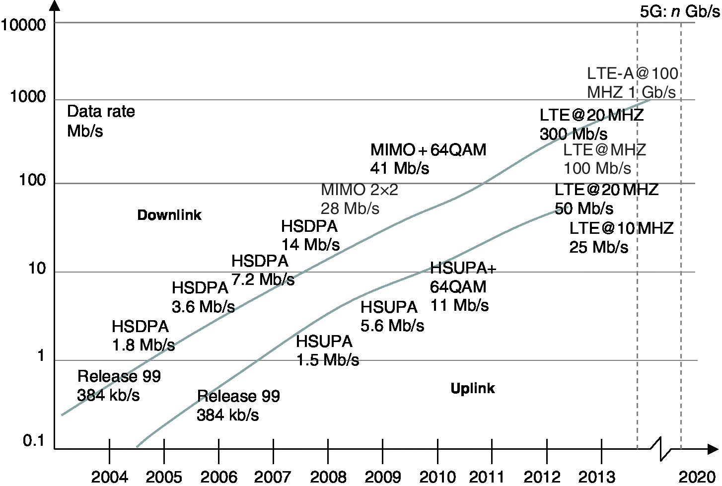
Figure 2.2 The general trends of 3G and 4G data rates. The planned 5G will offer considerably higher speeds
2.2.3 The Role of Apps
Since the early introduction of the Wireless Access Protocol (WAP) and respective browsers, mobile communications has evolved towards the increasing utilization of the Internet. HTML browsers on smartphones have provided further a logical access to the web, making WAP as such unnecessary. Also the provision of email access has been important in the high utilization of wireless access, and it can be generalized that the overall business environment has greatly benefited from email. Integrated browsers and email clients are nowadays included in smartphones and in many basic phones by default. The next step towards an even more interoperable era is the deployment of HTML5 and respective applications. In this way, the utilization of the network is optimized for a high‐quality user experience.
The provision of apps has also had a high impact on wireless communications. They enrich enormously user experiences and are highly popular due to the generally low or zero cost. This development has made the ecosystem for each smart device platforms an essential element – the availability or lack of popular apps may even mark the difference between successful device sales, so Original Equipment Manufacturers (OEMs), in addition to the hardware, need to guarantee the existence of this ecosystem. As a part of this ecosystem, the distribution channel, or application stores, functions as a logical means for the delivery of the apps. Furthermore, the creation of the ecosystem has initiated completely new business models where app developers together with operators and OEMs benefit from the app utilization. The business models are typically based on advertisements for the free‐of‐charge apps, low‐cost price for the payable apps and sharing of the revenue between the participating stakeholders [33].
Figure 2.3 summarizes this business environment. If any element is missing from the complete picture, or the element is not performing fully, such as insufficiently complete offering of apps per operating system, the business does not achieve optimal results which decreases the sales of the devices and further lowers the interest on developing new apps for that specific Operating System (OS). It is thus a matter of cooperation between all the stakeholders in order to ramp up the sufficiently profitable balance for all the elements of the ecosystem which eventually starts feeding itself automatically. Based on the short history of smart device markets, the app ecosystem is one of the most significant forces influencing the market share of user devices.
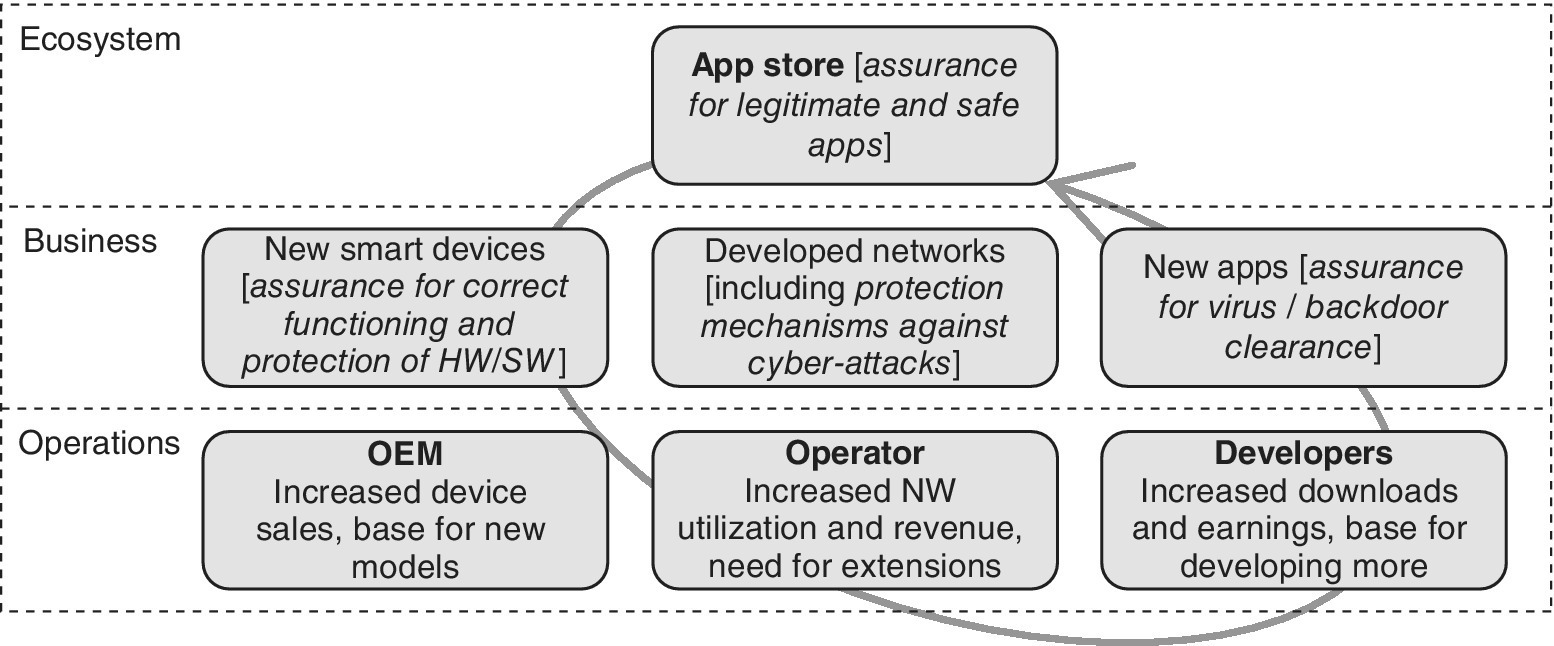
Figure 2.3 The app ecosystem depends on the available technologies and services
After the apps have been developed and the offering of many kinds of private and professional solutions have taken off, including games, utility solutions, integrated navigation and mapping solutions, banking and stock market solutions, the next significant step will be the evolved voice and video solutions. LTE/LTE‐A as such facilitates this development as the circuit‐switched domain is completely missing from the standards, making the system work purely in the packet‐switched domain. Thus, after the transition phase of voice calls handled via, e.g., Circuit Switched Fallback (CSFB), the more integrated solutions are taking voice and video services to next level.
Fully capable Voice over LTE (VoLTE) and Rich Communications Suite (RCS) will make the earlier mobile communications networks gradually unnecessary, although they will still serve as a base for operators for many years to come. It would logically not make sense to ramp down the already deployed networks at a fast schedule as the network utilization per generation is evolving gradually. As an example, the recent lowering of the GSM utilization means that there is huge amount of GSM‐capable handsets in the field, including GSM‐only equipment especially in an M2M environment. The transition strategies for the 2G, 3G and LTE/LTE‐A networks with frequency re‐farming optimization is thus one of the most important tasks for operators at the moment.
The evolution also brings along the offering of HTML5 technologies, with apps that are able to manage better data persistence, native code execution and multitasking. This evolvement will be seen increasingly in websites and browser‐based applications, which will pave the way for converging browser‐based applications and native applications. At least in theory, the role of operating systems and respective separated app ecosystems will thus lower in status. Also the always‐on connectivity will continue to evolve, with multitasking applications capable of keeping the connections alive becoming much more efficient. This, in turn, brings further challenges for the operators because of the probably exponentially increasing amount of signalling, e.g., due to keep‐alive or heart‐beat signalling which forces the apps to maintain the reserved bearer connections active. This may mean dramatic re‐dimensioning and increasing of signalling capacity – or actions from operators to guideline app developers not to waste the valuable capacity from the networks if other or less signalling can be used.
Observing the new mobile ecosystem as presented in Figure 2.3, the obvious security‐related question arises on how well the authenticity of the applications can be ensured. The official app store per OS representative and responsible aims to guarantee that the SW is free of malicious code via sufficiently thorough testing, evaluation and certification programs. Nevertheless, especially with the tight competitor environment and ‘rush’ for new app releases, there have been cases that revealed inappropriate SW embedded into the apps, or unnecessarily wide rights to access users’ data. Furthermore, the delivery of the apps via any other than the official ways always exposes a risk for embedded viruses, adware and other malware. If the installation of such non‐official apps is prevented by default by the device vendors, there are ‘temptations’ for end‐users to root the device, which opens potential security holes, so one of the easiest ways to ensure the protection level is that the end‐users hold off modifying their devices and utilize only trusted sources for SW downloading.
2.2.4 UE Application Development
The LTE/LTE‐A does not change as such the principles of the applications or app development that end‐users experience via terminals. Nevertheless, the LTE/LTE‐A does provide a base for more advanced apps due to the network data rate enhancements, lower delays and response times. Some possible new, higher quality apps might be related to time and jitter critical environments such as real‐time gaming, which requires heavy data transmission and high processor power which can be provided via the most advanced LTE/LTE‐A user devices.
The app development requires a Software Development Kit (SDK), which depends on the OS. The mobile OS is designed for smartphones, tablets, PDAs and other mobile devices. The typical mobile OS has elements familiar from the PC OS combined with other features optimized for touchscreen, mobile communications technologies, local connectivity like NFC, USB, Bluetooth and Wi‐Fi, navigation systems like GPS, additional integrated elements like cameras and sensors, and functionalities supporting, e.g., audio and video playback. Smartphones that contain mobile communications capabilities are typically based on two mobile OSs which are divided into the main software platform for the user interactions and a lower level OS managing the needed functions for the radio communications and hardware modules. Thus, the apps need to be developed for each operating system separately as they also manage the proprietary native functions of the devices.
The best way to initiate the mobile app development is to select the proper OS and to familiarize with the respective SDK functionality. This happens most fluently by creating initial, simple apps by reviewing examples of available apps in order to understand the philosophy of the code, libraries, APIs and manners to control the blocks of the smart device, such as GPS, sensors and input/output of characters. As is typical in any other computer language, the best way to understand the possibilities and limitations of the code is to investigate existing codes.
The following presents the main principles of the most popular SDK environments, i.e., Android that has the major part of the markets measured by the number of the devices and applications, followed by iOS. The rest of the OSs represent the minority in 2015 but can be an equally interesting base for new app developers. According to the statistics of Ref. [52] Android represented 85% share of global smartphone shipments in the second quarter of 2014 while Apple iOS, Microsoft, Blackberry and others had 11.9%, 2.7%, 0.6% and 0.2%, respectively.
2.2.4.1 Android
For app development in the Android environment, which is supported by a vast variety of device manufacturers, Ref. [51] contains the needed SDK and instructions for developers. For a new Android developer, the most straightforward way to proceed is to download the Android Developer Tool (ADT) bundle. It contains Android SDK components and a version of the Eclipse Integrated Development Environment (IDE) with built‐in ADT which is basically sufficient to initiate the actual programming. The components are: Eclipse and ADT plugin, Android SDK tools, Android platform tools, the latest Android platform and the latest Android system image for the emulator.
In the SW development, one of the tasks is to decide which Android version to select. The latest versions are by default backwards compatible with the earlier versions. Figure 2.4 summarizes the steps needed for the publication of an Android app, from the initial phase to its publicity.
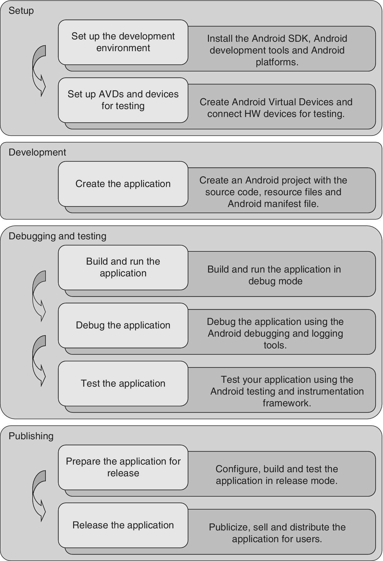
Figure 2.4 The development procedure for Android app development
2.2.4.2 iOS
The current SW development environment for the mobile environment of Apple is based on Xcode 5. It assists developers to create iOS apps. It includes automatic functions such as configuration of the apps in order to take advantage of the updated Apple services. It also manages images based on an asset catalogue, and assists in designing interfaces for iOS 7 and OS X. Furthermore, Xcode 5 is capable of analyzing the code, monitoring performance and testing apps. Ref. [53] includes the needed SW for the mobile environment of Apple and instructions for the app development.
2.2.4.3 Other Systems
BlackBerry is an open platform that provides a variety of development languages and runtimes according to the level of the skills of the developer. BlackBerry 10 offers the possibility to build integrated apps via C/C++/Qt, JavaScript, CCS, HTML, ActionScript, AIR and Java Android. The development can be done via native BlackBerry 10 SDK, HTML5 WebWorks, Runtime for Android apps, PlayBook and BlackBerry OS. More information about app development in the BlackBerry environment can be found in Ref. [54].
For app developers interested in the Windows mobile environment, a logical strategy would be to select the most recent OS version to ensure an up‐to‐date consumer base. The evolution version of Windows 10 contains further native functionalities that not all the previous HW variants are capable of supporting. Ref. [55] presents the SW and instructions for the Windows Phone app development.
In addition to the above‐mentioned variants, other OSs relevant to smart devices, tablets and other mobile devices include Firefox OS (Mozilla Foundation), Mer (Linux Foundation), Sailfish (Sailfish Alliance and Jolla), Tizen (Linux Foundation, Tizen Association, Samsung and Intel) and Ubuntu Touch (Canonical Ltd., Ubuntu community). These are typically based on free and open‐source license while the iOS (Apple), Windows Phone (Microsoft) and BlackBerry OS (Blackberry Ltd.) are proprietary solutions.
2.2.5 Developers
The app ecosystem includes an essential element, the SDK, for each mobile application platform. The SDK provides access to the tools and set of Application Programming Interfaces (APIs) that are required for developing applications. Furthermore, the application framework facilitates the reuse of development components which results in ever richer and attractive apps in a fast schedule. The application framework also provides the means to take advantage of the HW of the user device, including supported sensors and the possibility to access location information of the user.
Distribution of the apps happens via the mobile application marketplace. The typical procedure is that the respective provider verifies the correct functioning, sufficiently high quality and safety of the apps, and places the certified apps to be downloaded by the users. The marketplace also functions as a forum where users can provide comments and evaluations. The marketplace typically is operated by OEMs, service providers, mobile application platform vendors and/or other parties.
The amount of apps that are based on intensive signalling between the UE and network are increasing. As identified in Ref. [34], chat‐type of mobile apps may constantly poll servers for updates and for providing always‐on immediacy which is thought to increase user experience. This background signalling results in devices to constantly connect to the mobile communications network which, in turn, causes connection attempts with numerous signalling messages. In many cases, this background signalling is merely additional load from the operator’s point of view due to the fact that no updates are available.
The level of the background signalling load and thus the impact on the network capacity utilization depends heavily on the application profile. Video streaming requires wide bandwidth yet only a low amount of signalling. On the other hand, the messaging type of apps and social media utilization function normally with minimum bandwidth requirements but triggers at the same time a big amount of related signalling, which in turn may cause challenges for the operators along with the increased amount of users. The challenge is getting more critical because operators need to optimize constantly the limited resources, which means that these background signalling generating apps need to be optimized too, in order to minimize the impact on the QoS level experienced by other users.
The operators had strong control over the devices prior to the introduction of smart devices. The new technical solutions, together with a highly changed business environment where apps are the critical element for assuring competitiveness, mean that this control is lowering. The smart device markets are growing fast in all the regions worldwide. According to Ref. [35], 30% of all handsets sold in 2011 were smartphones, compared to approximately a 20% share of the handset market in 2010. About 10% of the global user base had subscribed via smartphones in 2011, and the Figure 2.1 indicates that the growth of smart device utilization has been significant.
As the hardware develops and the memory storage increases, users are able to download and utilize very large amounts of apps. The sufficient resources for the downloading and app signalling must thus be assured. As a solution for the possible non‐optimal messaging of some apps, there may be a need for guidelines for the app developers to minimize the signalling. It is thus a matter of balancing the bit transfer in such a way that the user experiences are sufficiently good, the app business is sustainable, and the operator’s network resources are not exploited.
The critical elements for the over‐signalling are the Radio Network Controller (RNC) in 3G, and the Mobility Management Entity (MME) in LTE/LTE‐A. In the worst case, heavy background signalling can cause temporal overload which has effects on the network resource availability and QoS for all the users. The optimization of the background signalling is thus an increasingly important task of the network operators, which requires cooperation between the operators, app developers and app businesses.
2.2.6 The Role of the SIM/UICC
An important innovation from the GSM era for current and future mobile systems is the SIM which still defends its position, providing one of the best protection mechanisms in the telecommunications networks. SIM, and its variant for the 3G era, the UICC with respective internal applications for different mobile networks, is a smartcard fulfilling the role of an SE. It is based on ISO/IEC 7816 standard with extensions for the wireless payment and access solutions via NFC via the ISO 14443 standard.
The SIM provides high security as a basis for the communications. In addition to the protection, it provides the radio network communications, it is a tamper‐resistant physical HW element which is able to maintain the data protected. One of the security threats may be related to the intention to physically replicate the card information by making an exact copy of it, although even this does not reveal the cryptographic data in plain format. Furthermore, if such a copied card is utilized in the network (and thus a copy of the Mobile Subscriber’s ISDN Number (MSISDN) is used), the operator’s security breach analysis would reveal the suspicious communications and prevent the calls.
The role of the embedded Security Element (eSE) is currently changing the ways of how subscription management is handled. Some examples are autonomic telemetric or home utility equipment which can be managed remotely to switch the serving operator or subscriber’s profile. As another example, the automotive industry is currently including mobile subscriptions into their vehicles. The fast development of connected cars is causing issues which require novelty protection mechanisms, the HW‐based SE being one of the strongest components in the overall shielding [6]. The remote management of such subscriptions is especially beneficial to optimize the logistics as the cars can be transported to various countries from the production facilities, and the local subscription can be loaded, activated, changed and deleted during the lifetime of the vehicle depending on the preferences of the current and future owners.
One of the current trends in the consumer markets is the increased utilization of wearables like smart watches and even computers that are attached to clothes [13]. As they may be considerably small, they benefit greatly from the smallest Form Factors that the permanently installed eSE can provide compared to the physically removable SIM/UICC cards. As these devices are obviously equally vulnerable to security attacks, it is highly important to ensure the proper shielding of the remote management of the subscriptions. At present, standardization of interoperable and dynamic subscription management is under work, and is explained in more detail later in this book.
The SIM/UICC, either as a removable or as an embedded variant, is a suitable base for the combined functionalities that include telecommunications (authentication, authorization and secure radio interface) and other services like banking and physical access. Furthermore, it can be used as a secure data storage for the user’s information. Along with the new methods under work and deployment, like HCE that may be based on one‐time tokens and cloud storage, the combination of related services with physical SIM/UICC could provide a good level of security.
2.2.7 Challenges of Legislation
Protection against fraud as well as ways for sanctioning the malicious acts related to the early mobile communications networks was challenging as the legislation typically became outdated compared to the new aspects of such fast developing technologies. As an example, in the United States the Telecommunications Act of 1996 was the first major overhaul of telecommunications laws. The main goal of the new law is to liberate the communications business by allowing fair competition in any market.
One of the first type of fraud – in addition to the by then straightforward eavesdropping of unprotected radio channels – was the cloning of mobile equipment credentials and thus the telephone number of analogue systems. This resulted in the need for updating the legislation by criminalizing the use, possession, manufacture and sale of cloning hardware and software. As the digital mobile communications systems were already much better prepared against such frauds, based on the lessons learned, this types of fraud has practically disappeared.
A cloned mobile device refers to equipment that is reprogrammed and signals to the network the copied or modified HW ID. Nevertheless, the cloning of the hardware is in practice only relevant for 1G networks like Advanced Mobile Phone System (AMPS) and Total Access Communications System (TACS) that are now obsolete, and the still existing ‘basic’ Code Division Multiple Access (CDMA) devices with the subscription ID embedded into the HW. As has been the case with GSM and other enhanced 3GPP systems, the subscription is now stored in the removable SIM card, which makes the cloning of the device irrelevant. To provide an extra layer of security against mobile equipment cloning, CDMA device HW have a unique Electronic Serial Number (ESN) and telephone number (MIN) while the 3GPP devices supporting GSM, Universal Mobile Telecommunications System/HSPA (UMTS/HSPA) and LTE are equipped with an International Mobile Equipment Identity (IMEI) code.
Not only has the legislation been updated but also the preventing technologies have taken major steps in order to protect users and operators. On the other hand, the development of the mobile communications towards IP technologies, the same type of threats familiar from the public Internet are becoming more relevant in mobile communications. The Long Term Evolution/System Architecture Evolution (LTE/SAE) network is based completely on IP which means that the same threats are valid there as in any other packet network. As for the security processes, the main aim of the LTE/SAE operator is to reduce the opportunities for the misuse of the network.
2.2.8 Updating Standards
The original ETSI specifications, GSM 02.09 and GSM 03.20, created the basis for GSM security solutions. Since the early days of the 3GPP 3G system, security has been identified as an essential part. From the first Release 99 specifications, there have been numerous completely new specifications produced by the SA3 Working Group, including the main definitions found in TS 33.102 (3G Security Architecture). The 3GPP has also produced advanced specifications for security, taking into account IP principles as the mobile networks are developing towards IP Multimedia Subsystem (IMS) and all‐IP concepts.
The 3GPP SA3 Working Group has created new specifications for the LTE/SAE protection under TS 33.401 (Security Architecture of the SAE) and TS 33.402 (Security of SAE with Non‐3GPP Access). The LTE system provides confidentiality and integrity protection for the signalling between the LTE‐UE and MME. The confidentiality protection refers to the ciphering of the signalling messages. The integrity protection, in turn, assures that the signalling message contents are not altered during transmission.
The LTE radio interface traffic is secured by using the Packet Data Convergence Protocol (PDCP). In the control plane, the PDCP provides both encryption and integrity protection for the Radio Resource Control (RRC) signalling messages that are delivered within the PDCP packet payload. At the user plane, the PDCP performs encryption of the user data without integrity protection. It should be noted that the protection of the internal LTE/SAE interfaces like S1 is left as optional.
2.2.9 3GPP System Evolution
Figure 2.5 presents the main elements and interfaces of the 3GPP GSM EDGE Radio Access Network (GERAN) (GSM and GPRS), Universal Terrestrial Radio Access Network (UTRAN), Core Network (CN), Enhanced UTRAN (E‐UTRAN) (LTE radio network) and Enhanced Packet Core (EPC) of the LTE.
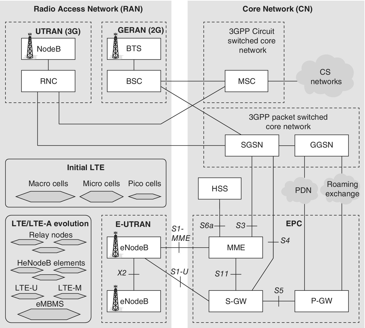
Figure 2.5 The main elements of 3GPP networks. The evolution of LTE brings new elements for, e.g., eMBMS, as well as cell extensions like relay nodes and Home eNB elements, while LTE also extends to unlicensed bands (LTE‐U) and is optimized for IoT/M2M environment (LTE‐M)
Being digital, the first phase of ETSI‐defined GSM networks included the basic security like authorization and radio interface encoding. As another difference between earlier, 1G analogue systems, the concept of the smartcard in the form of a SIM was introduced to provide fluent user information portability between devices. Along with the further development of the 3G system, this base has remained compatible with GSM network architecture. Since the first GSM networks, the 3GPP systems have been developing. After the introduction of 3G UMTS and Release 8/9 LTE, operators have largely deployed also Release 10 and more advanced LTE networks in a global level. The Rel. 10 and beyond introduces completely new concepts like the home eNB that considerably change the network planning from highly controlled networks with known base station locations towards highly fragmented and unpredictable configurations as the end‐users are able to easily purchase home base stations and freely deploy and switch them on and off.
Release 10 also brings new aspects in the wireless security as the home eNBs are exposed to potentially malicious intentions. Thus, the network topology converts as a mix of different types of base stations. In this book, the term HetNet refers to the environment with many different eNB sizes within the same Radio Access Technology (RAT), while the term ‘Heterogenous Network’ refers to the wider concept which consists of different base stations over various RATs, such as a combination of LTE and Wi‐Fi with data offloading properties.
2.3 GSM
When the first phase of GSM was under specification back in the late 1980s, the security aspects were quite different from the current world. Many of the modern threats we face today had not been experienced by the operators or users, such as mobile phone viruses and DoS attack attempts. At that time, the GSM system needed to have simply as good as or better security level than that of fixed networks. Since both GSM and fixed telephony networks were isolated from the external world, it was straightforward to comply with this requirement. The essential additional security aspects of GSM that ensured the radio interface protection at that time are the subscriber authentication and authorization, radio interface encryption for both signalling and communications, and the utilization of temporary identity during the communications.
2.3.1 The SIM
The SIM of GSM is a contact‐based smartcard relying on the definitions of ISO/IEC 7816. SIM cards come in several sizes which are referred to as Form Factors (FFs). The first form factor 1FF refers to the credit card sized frame that was planned to be used in the first phase deployments in the early 1990s. In practice, the form factor 2FF with a size of approximately 2.5 × 1.5 cm initiated the commercial GSM era. After that, the further reduced cards are 3FF (micro card) and 4FF (nano card). Chapter 4 presents a more detailed description of the physical aspect of the SIM and its evolved variants.
The GSM SIM contains permanent records of the subscriber’s identity (Ki key) and operator‐specific authentication algorithms A3 and A8. In contrast, the standard‐defined A5 algorithm is stored in the mobile equipment hardware. There are currently several versions of the radio interface encryption algorithm defined and available:
- A5/0, which refers to the unprotected connection without encryption algorithm.
- A5/1, which has offered good protection in the initial phase of GSM but has been compromised as a result of processor development and enhanced attack techniques. It is possible to find the Ki via brute force attacks combined by rainbow tables which significantly reduces the time for exploration [18].
- A5/2, which has been less protected since its deployment. The communications can be intercepted in real time by authorities [14].
- A5/3, which is a further developed variant but which may suffer from modern attack techniques [15].
- A5/4, which is the most recent updated algorithm currently providing the highest GSM security level.
The A5 algorithm is stored in the mobile terminal for the GPRS service, too. In that case, there is an adjusted A5 algorithm in use, the GPRS Encryption Algorithm (GEA), so the same SIM card functions in order to use both GSM and GPRS services.
In addition to the permanently stored information by the MNO, the user can store dynamic data such as phone numbers connected with alphanumeric information and short messages on the SIM card, according to the memory limitations of the card. The subscriber can, in principle, use any GSM terminal with the SIM card. Thus a subscriber to a European GSM 900 or GSM 1,800 network can use his/her own SIM card and a suitable mobile phone to use GSM 850 or GSM 1,900 networks in the United States, as long as the operator in question has signed a roaming agreement with the subscriber’s home network operator. In practice, the GSM base band chip contains by default these quadra‐bands and often also other GSM band extensions so the same GSM device HW are typically capable for global roaming.
The benefits of the SIM card are, e.g., the safety functions, interoperability with in principle any GSM phone and network, and the flexible adding and removing of services. As the SIM card is based on a regular smartcard, it is possible to combine functions unrelated to the GSM network such as an NFC‐based bankcard app, making it a multifunctional card for a multitude of different services requiring high levels of security.
The SIM card of the GSM system is one example of contact smartcards; other examples include prepaid calling cards, bankcards and access control cards. Such smartcards have been specified in ISO series 7816 standards for the contact cards, and in ISO series 14443 for the contactless environment, which in mobile communications systems is done via NFC. More detailed descriptions of these SIM variants can be found in Chapters 4 and 5.
The user can activate and specify a Personal Identity Number (PIN) code, which the terminal requests when the device is powered on. An exception is the European emergency number 112, US emergency number 911, and other national variants, which are possible to dial without the PIN code. By default, it is possible to call emergency numbers even without a SIM card. The PIN code consists of a set of digits. If the PIN code function has been activated on the SIM card and an incorrect PIN code is entered three times, the SIM card starts to request a Personal Unblocking Key (PUK) code. If an incorrect PUK code is entered 10 times, the SIM card is blocked permanently.
The same principle of the physical card is utilized in 3G UMTS/LTE and 4G LTE‐Advanced devices in the form of the more advanced UICC and its respective telecom apps, and the security functions have also been further developed as can be depicted from Figure 2.6.
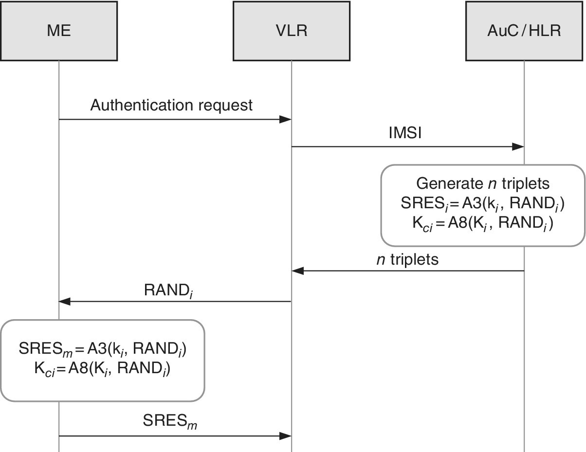
Figure 2.6 The signalling chart for the delivery of triplets from the AuC/HLR to VLR
2.3.2 Authentication and Authorization
The GSM system may check the user’s permission to utilize the network as a part of the call set up, location area update and in the termination phase of the call. This happens with the help of the Authentication Centre (AuC). Even though the AuC is a separate logical functionality, it is typically integrated physically into the HLR because they do rely on the joint communication link.
Each subscriber is given a subscriber‐specific key Ki which is stored in the user’s SIM as well as in the AuC. This happens in the provision phase when the new subscription is created, and the subscriber profile is activated in the HLR of their home network. Figure 2.7 presents the security procedure in the call set up phase.
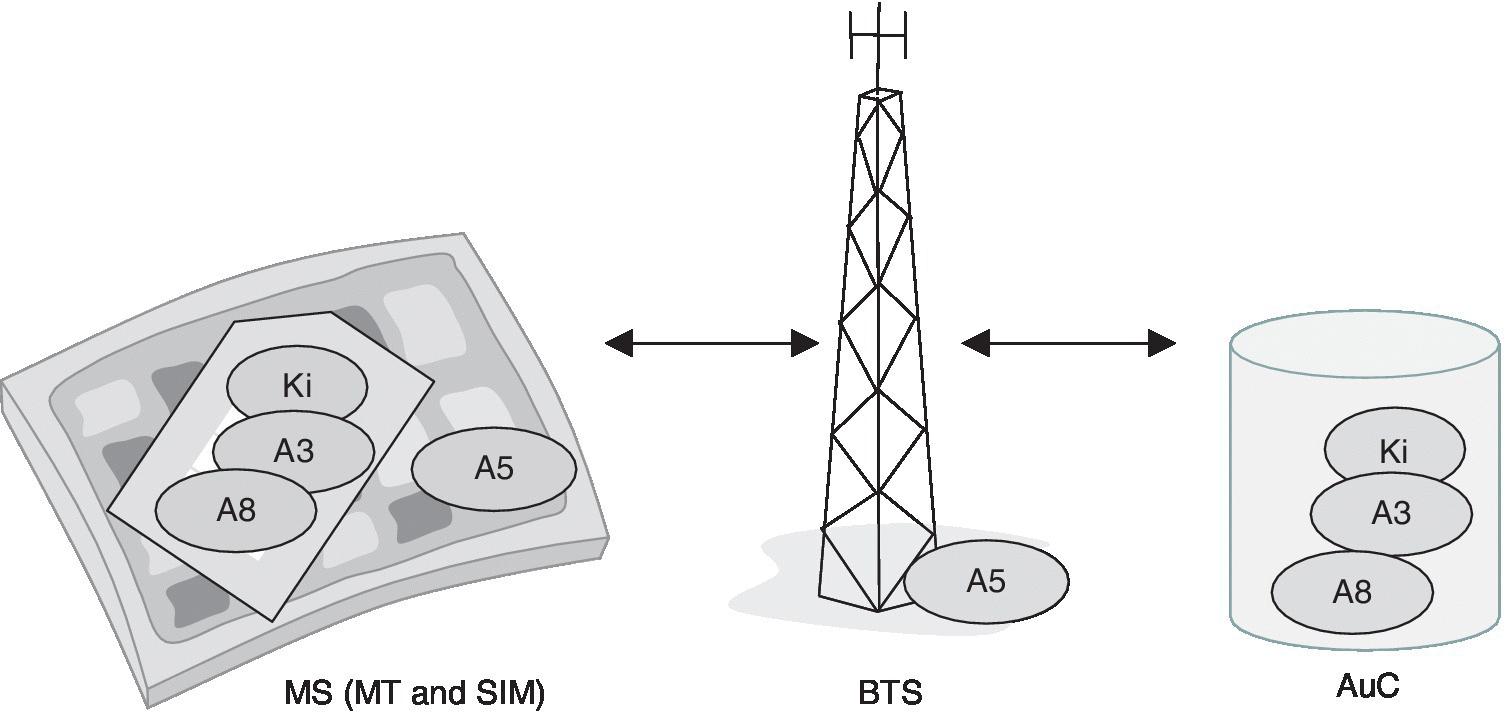
Figure 2.7 The subscriber‐specific Ki, as well as the A3 and A8 algorithms are stored in the SIM and the AuC for the authentication, authorization and session key creation. The A5 algorithm is stored, in turn, in the HW of the Mobile Terminal (MT) and in the Base Transceiver Station (BTS) equipment for protecting the radio interface
The AuC calculates in advance a security parameter triplet, or a set of these. The triplet contains parameter values for random number (RAND), SRES (Signed Response) and Kc (Temporal Key). This triplet is transferred and stored into the VLR to which the user is currently subscribed as shown in Figure 2.8. It should be noted that the user‐specific Ki key is never transferred or exposed from the AuC or SIM.
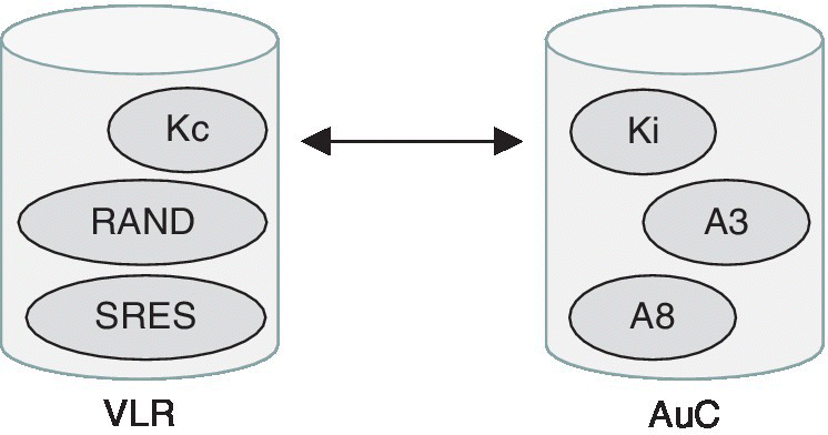
Figure 2.8 By utilizing Ki, A3 and A8, the AuC calculates the triplet, i.e., values for the Kc, RAND and SRES. The triplet is stored in the VLR
As shown in Figure 2.9, the authentication happens in such a way that the AuC generates a new value of RAND. The value range of RAND is 0.2128–1. This value is sent as a part of the initial signalling via the Stand Alone Dedicated Control Channel (SDCCH) to the SIM.
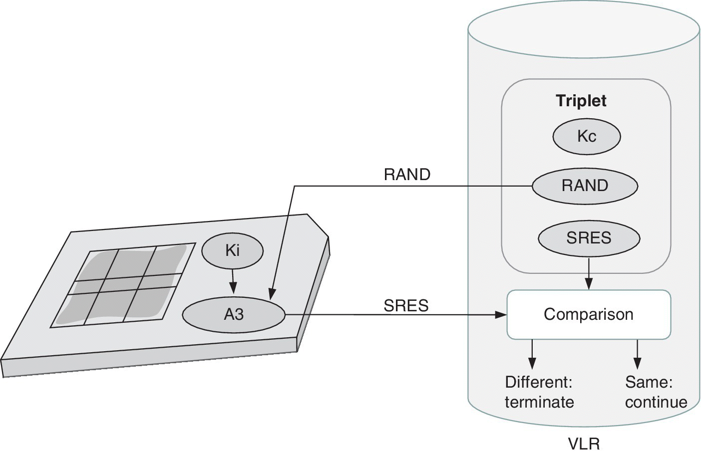
Figure 2.9 The authentication and authorization is done by A3, RAND and Ki
In the next step, based on the received RAND and the Ki key and A3 algorithm stored in the SIM, the SIM calculates the SRES. Based on the same information, the AuC has also calculated the SRES in advanced. Now, the user device sends the SRES value to the corresponding VLR via SDCCH, and the VLR compares the SRES values it has received from the SIM and AuC. If the SRES values are different, the call attempt is terminated. The SRES may be incorrect if the user has an incorrect A3 or Ki key. The network reasons thus that the call attempt is not authorized.
The A3 algorithm is operator‐specific and resides in the SIM and AuC. It is recommended to use a sufficiently secure and complicated algorithm in order to assure that the Ki key cannot be calculated via RAND and SRES values. The A3 may be public, but typically the intention is to keep it classified. The length of the RAND is 128 bits and the SRES always consists of 32 bits. The length of the Ki key is operator‐specific.
2.3.3 Encryption of the Radio Interface
As soon as the network has concluded that the user is authorized, i.e., the SRES is noted correct, the signalling and all the communications will be encrypted. This happens in two phases. First, a temporal key is generated, and secondly the key is utilized for the actual radio interface encryption.
Both the SIM and AuC calculate the connection‐specific key Kc by utilizing the same RAND value as described previously, and by applying the A8 algorithm that is stored in the SIM and AuC. Figure 2.10 clarifies the procedure. The length of the Kc is always 64 bits. If the key is shorter, zero bits are padded. The Kc is calculated separately for each connection to provide additional protection. The A8 algorithm is operator‐specific, and the same principles for its recommended complexity apply as for the A3. As the A3 and A8 are both operator‐specific, they can also be combined. It is of high importance to assure the combined algorithm A3/8 is not too simple and that the Kc can be protected.
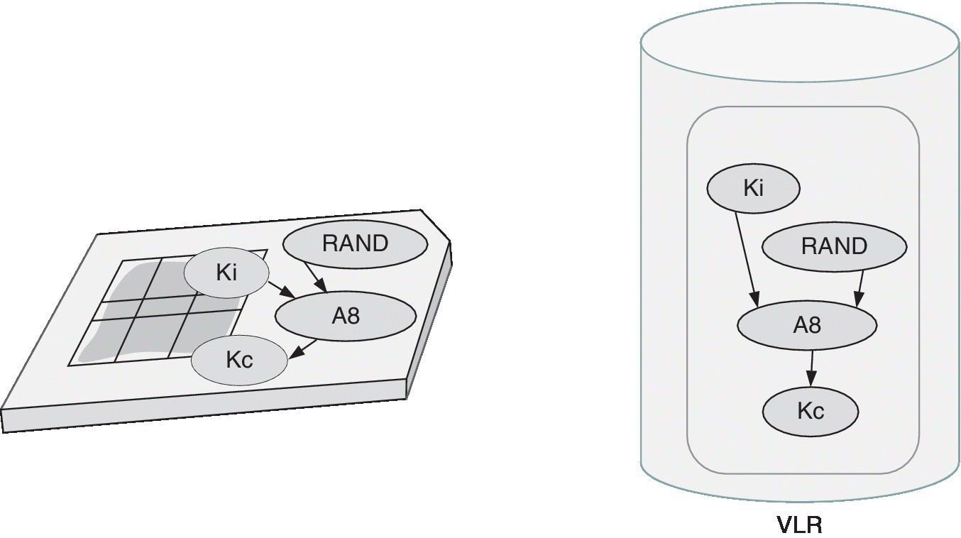
Figure 2.10 Kc is calculated with the A8 algorithm, based on Ki stored permanently within SIM, and RAND produced in the AuC/VLR
As soon as the Kc is calculated, the actual encryption of the radio interface takes place as shown in Figure 2.11. From this point onwards, all the communications between the UE and BTS is scrambled, including the signalling such as location area updates and handovers, voice and data calls as well as short messages and multimedia messaging.
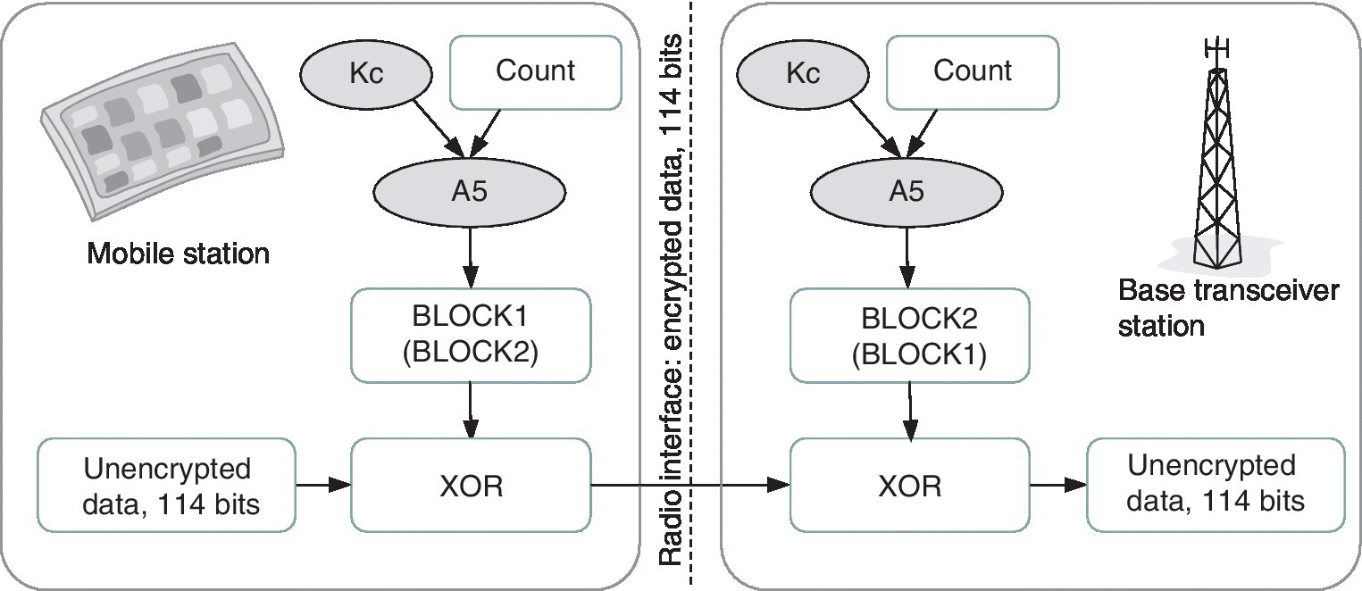
Figure 2.11 The encryption of the GSM radio interface takes place via the A5 algorithm
For the radio interface encryption, the same connection‐specific Kc and A5 algorithm are used. The algorithm takes as an input the Kc and the superframe number COUNT of the GSM radio interface timeslot structure, and the result is fed into a logical Exclusive Or (XOR) operation together with the single burst information of 114 bits.
The superframe cycle of the GSM system is about 3.5 hours, and the length of the COUNT is 22 bits. The block that A5 produces is called BLOCK1 or BLOCK2. BLOCK1 is utilized for the encryption and BLOCK2 is utilized for the decryption as presented in Figure 2.11.
Because the COUNT gets different value for each block, the scrambling of each burst’s 114 information bit are different from previous ones. If the connection takes longer than the repetition cycle of the superframe, the COUNT values start repeating accordingly. The values for Kc and RAND are calculated from scratch each time a new connection is established.
The efficiency of the A5 algorithm does not depend on the non‐publicity as each operator has a description of it. In any case, the GSM Association has decided to keep it confidential, so it has not been officially published. According to the GSM security specifications, there can be seven different A5 algorithms. At the moment, four algorithms have been produced, A5/1, A5/2, A5/3 and A5/4. The original A5/1 is designed as a strong one whereas the A5/2 is lighter, the latter being easier to decrypt, e.g., by governments. For the case where no encryption is used, A5/0 is utilized. The most recent and currently best protected A5/4 algorithm for 128 bit cases is defined as of Release 9.
At the start of the connection, the UE informs the network about the desired version of the A5 algorithm. If the AuC does not have the common algorithm, and the network does not support non‐encrypted calls, the call attempt is unsuccessful. If the network supports non‐encrypted connections, the call is established without encryption. In this case, the user will notice respective information on the display of the device to indicate that the communications is not encrypted. If common algorithms are present, the network decides which of the versions will be utilized for that connection.
2.3.4 Encryption of IMSI
The International Mobile Subscriber Identity (IMSI) is always a priority identifier within the GSM network, but operators typically want to avoid exposing it in the radio interface signalling. Instead, the Temporary Mobile Subscriber Identity (TMSI) may replace the IMSI. This gives additional means for the user identity protection. Nevertheless, the support of TMSI is not mandatory, so each operator decides the strategy for its use. If it is supported, the UE gets a new value each time it registers to a new Location Area (LA). The TMSI is sent over the radio interface encrypted via SDCCH.
2.3.5 Other GSM Security Aspects
2.3.5.1 Radio Parameters and Topology
Additional protection for eavesdropping is achieved via slow frequency hopping which has an interval of a single burst. Another aspect that increases the challenges in systematic user‐specific eavesdropping or for getting location information is the relatively small cell sizes in urban areas and in the moving environment. Furthermore, the cells are typically sectorized, and power control as well as discontinuous transmission cause extra challenges for focused monitoring.
2.3.5.2 Equipment Identity Register
Each mobile phone (GSM and the devices of later generations) are tagged with an identity number, which is also stored in the Equipment Identity Register (EIR). The identity number has nothing to do with the subscriber number, and it indicates only the HW equipment. The EIR signals with the Mobile services Switching Centre (MSC), so that the network can, if necessary, check the equipment information. Information on faulty or stolen phones or mobile phones under surveillance can be stored in the EIR. It is possible to prevent the use of a mobile phone via the EIR which can store the IMEI codes.
The EIR consists of white, grey and black lists. The white list contains all equipment types that have been type approved and allowed to be used in the networks. The grey list contains equipment which needs be tracked or followed up, such as equipment which has received only temporal and conditional acceptance in the type approval process. The black list contains illicit equipment, such as stolen phones or equipment which has not received type approval. Even if a phone were placed on the black list, calls could be switched to the emergency number.
The international version of the EIR is called the Central EIR (CEIR), and is nowadays coordinated by the GSMA under the name IMEI Database as indicated in Ref. [61]. The CEIR compiles the information on illicit equipment that is delivered via an international packet‐switched network. When information on stolen or illicit equipment is added to the black list of one operator, the information is also passed on to the CEIR and to the EIRs of all operators connected to the CEIR.
2.4 UMTS/HSPA
2.4.1 Principles of 3G Security
When the UMTS was specified, the stakeholders already had experience from the GSM networks that helped in the further development of protection mechanisms. The main principles of the UMTS protection are that it is based on the GSM security solution, that it takes into account the noted GSM weaknesses, and that it adds further security for 3G services.
Concretely, the trust principle of the UMTS was enhanced in such a way that it also includes the mutual authentication between the system and the user. This avoids the potential utilization of fraudulent spoof base stations which could capture user communications. There have also been enhancements in the protocols and algorithms, including the EAP‐SIM for the 3G‐WLAN interworking [3]. In the 3G, the related term is User Authentication, whereas the GSM utilizes the term Subscriber Authentication. More information on the GSM BTS vulnerabilities can be found in Refs. 1,2,4,5,11,19–21.
The UMTS also enhanced the radio interface encryption by introducing longer keys, publicly verifiable algorithms and multiple radio interfaces between the terminal and base station. Also the functionality of the SIM that is referred to as the Universal SIM (USIM) in the 3G network was enhanced. Furthermore, the encryption and decryption functionality of the radio interface is moved to a deeper level, now residing at 3G RNC compared to the GSM which locates the decryption functionality at the base station. Figure 2.12 summarizes the 3G security architecture, and Figure 2.13 depicts the role of the UMTS interfaces in the security procedures [17].
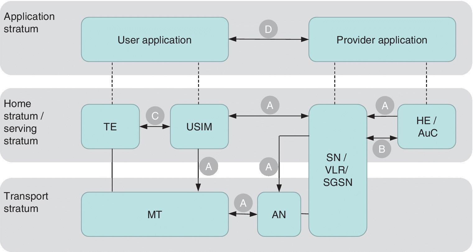
Figure 2.12 The 3GPP security architecture. The symbols of the figure refer to the following: (A) network access security; (B) provider domain security; (C) user domain security; and (D) application security
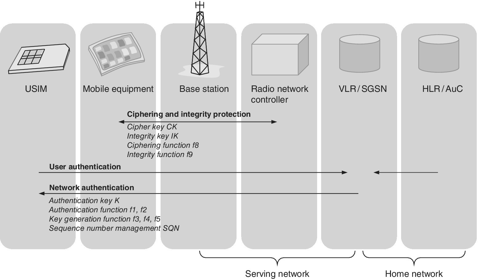
Figure 2.13 The role of the UMTS interfaces in 3GPP security procedures.
Source: Reprinted from [38] by courtesy of ETSI
The UMTS authentication and key agreement protocols, the UMTS Authentication and Key Agreement (AKA), are applied in the UMTS networks. Furthermore, 3GPP defines EAP‐AKA for the authentication of the users that connect via WLAN, and EAP‐AKA’ to authenticate users that connect via trusted non‐3GPP access networks to the LTE core, i.e., Enhanced Packet System (EPS).
The UMTS specifications define three entities related to the authentication: the Home Environment (HE) which means the home network; the Serving Network (SN) which can be the home network or the roaming network; and the USIM (UICC). At the start of the call attempt, the SN assures the user’s identity is correct via a challenge–response procedure as is the case in GSM. In the UMTS, the User Equipment (UE) also makes sure that the SN is authorized by the HE to execute this procedure via the mutual authentication.
2.4.2 Key Utilization
The UMTS authentication is based on the user’s permanent key K which is stored in the HE database as well as in the USIM. For the encryption and integrity check, additional temporal keys are generated. As soon as the user is identified, the actual authentication takes place via an AKA procedure. For that, an authentication vector is generated by the AuC and stored to the respective Visitor Location Register/Serving GPRS Support Node (VLR/SGSN). At the start of the authentication procedure, the VLR (in the case of a circuit‐switched (CS) call) or SGSN (for packet‐switched (PS) calls) sends a user authentication request to the UE accompanied by two parameter values for RAND and Authentication Token (AUTN). The USIM of the UICC receives these parameters. The USIM already has the permanent UMTS key K which is used to calculate the authentication vectors prepared previously by the AuC. This happens via multiple algorithms, and the outcome is the assurance if the AuC actually generated the AUTN. Now, if the AuC is noted as correct, a Response (RES) value is sent back to VLR/SGSN which, in turn, compares it with the Expected Response (XRES) generated at the AuC. If the RES and the XRES are the same, the authentication phase is passed and the call can be initiated.
Along with the authentication procedure, the temporal 128‐bit Cipher Key (CK) for radio access network encryption and 128‐bit Integrity Key (IK) values are calculated by the USIM which transfers them to the mobile equipment for the actual encryption. On the other hand, the CK and IK are transferred from the AuC to the VLR/SGSN. As the encryption and integrity procedure is initiated, these values are transferred to the RNC via the RAN Application Protocol (RANAP) message’s Security Mode Command. The RNC thus takes care of the actual encryption of the UMTS. The aim is to assure the user and network that neither the CK nor the IK have been used previously. As a basis for this, the authenticated management field in the HE and USIM have authentication key and algorithm identifiers, and they limit the CK and IK usage before the USIM triggers a new AKA. The pre‐requirement for the AKA that the UMTS utilizes is that the AuC and USIM share the user‐specific key K as well as the message authentication functions (f1, f1*, f2) and key‐generating functions (f3, f4, f5). The AuC is able to generate random integers and sequence numbers while the USIM is able to verify the freshness of these sequence numbers.
Prior to the ciphering, the UE and the RNC agree the version of the encryption algorithm. The algorithm set is enhanced and there is more variety in the UMTS compared to the GSM. The encryption is performed in the Medium Access Control (MAC) or Radio Link Control (RLC) layer. Each Protocol Data Unit (PDU) increases a relatively small counter. This counter is called the Connection Frame Number (CFN) in the MAC layer, and the RLC Sequence Number (RLC‐SN) in the RLC layer. A Hyperframe Number (HFN) counter with a larger value range is also applied. The combination of all these counters is referred to as COUNT‐C.
To complement the encryption, some additional inputs are needed: BEARER (radio bearer identity), DIRECTION, i.e., indication of the Uplink (UL) or Downlink (DL) encryption, and LENGTH (size of data to be encrypted). The integrity protection mechanism is also applied in the RRC layer with the IK. The RRC message together with DIRECTION (1 bit), IK (128 bits), COUNT‐1 (32 bits) and random number FRESH (32 bits) are fed into the one‐way function f9.
The UMTS AKA utilizes the variables and functions listed in Table 2.1. Based on the variables, the result is a set called Quintet which consists of the values of RAND, XRES, CK, IK and AUTN variables.
Table 2.1 Variables used by AKA in UMTS
| Variable/function | Description | Length/bits |
| AK | Anonymity Key f5K(RAND). The f5 is a key‐generating function | 48 |
| AMF | Authenticated Management Field. Provides secured channel from HE to USIM in order to define operator‐specific options during the authentication procedures | 16 |
| AUTN | Network Authentication Token (concealment of SQN and AK optional) SQN ⊕ AK || AMF || MAC | 128 |
| CK | Cipher Key f3K(RAND). The f3 is a key‐generating function. | 128 |
| IK | Integrity Key f4K(RAND). Designed for integrity protection of signalling information. The f4 is a key‐generating function | 128 |
| K | User Key | 128 |
| MAC | Message Authentication Code (based on RAND, SQN and AMF) f1K(SQN || RAND || AMF). The f1 is a message authentication function. | 64 |
| RAND | Random challenge which the AuC generates | 128 |
| RES | Based on RAND, USIM calculates user response f2K(RAND). The f2 is a message authentication function (possibly truncated) | 32–128 |
| SQN | Sequence Number | 48 |
| XRES | Based on RAND, AuC calculates expected user response f2K(RAND) | 32–128 |
2.4.3 3G Security Procedures
The UMTS AKA protocol takes into account the compatibility with the previous GSM as widely as possible, yet adds security functionality specific for the 3G system. The original architecture of the GSM for the symmetric challenge–response functionality is thus still valid in the UMTS networks, while the 3G‐specific enhancements include (1) authentication of HE to the user; (2) agreement on an IK between user and SN; (3) mutual assurance of freshness of agreed CK and IK between SN and user; and (4) joint specifications between 3GPP and 3GPP2 for providing global 3G roaming.
The following description summarizes the 3G security functionality while a more complete UMTS security description can be found in Ref. [64], and a more thorough analysis of the functionality of 3G AKA can be found in Refs. [25,26] which detail the 3GPP methodology for the authentication vectors as listed in Table 2.1. Figure 2.14 depicts the related high‐level procedures. As a basis for the 3G AKA, there is a shared user‐specific key K in both AuC as well as in the user's USIM. The AKA also uses message authentication functions f1 and f2, and key‐generating functions f3, f4, f5.
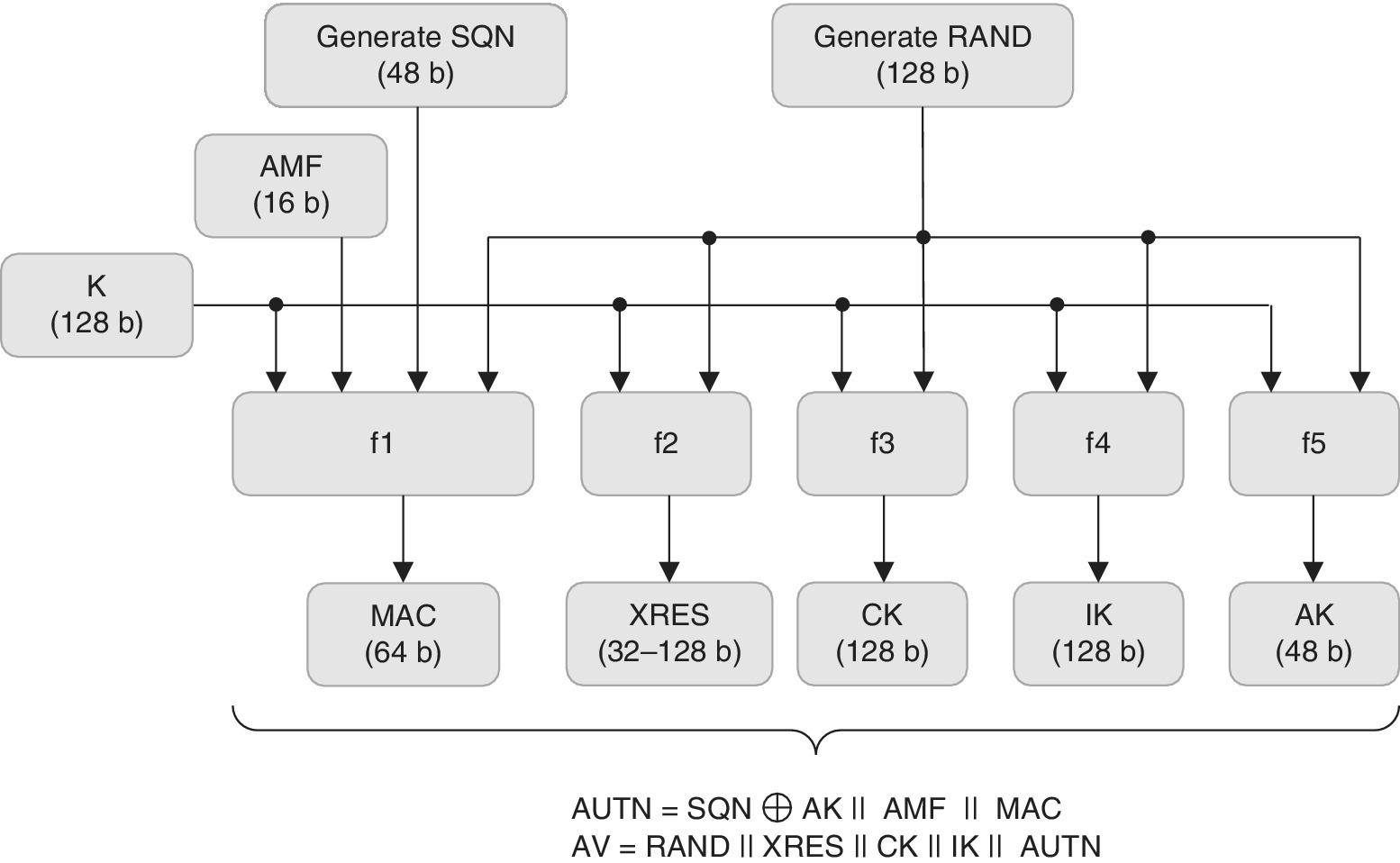
Figure 2.14 The principle of the 3G authentication vector generation as described in 3GPP TS 33.102
There are two phases in the 3G AKA, which are the generation of authentication vectors procedure and posteriorly the authentication and key agreement procedure. The first phase relates to the generation of authentication vectors. In the initial stage, the HE/AuC receives an authentication data request from an SN which triggers the creation of a set of arrays of Authentication Vectors (AVs) in HE/AuC. The practical number n of these vectors can be around five. Each array of AVs consists of RAND, XRES, CK, IK and AUTN. The HE/AuC then sends this set of n arrays of AVs back to the requesting SN.
The second phase is the AKA procedure. The SN, via VLR or SGSN, selects one AV i from the received set of n arrays of vectors. It can be of any from the set of 1 … n. Based on this information, the SN sends RAND(i) and AUTN(i) to the user. Now, as a first step, the USIM makes sure that the AUTN(i) has the correct AUTN. If all is in order, the USIM calculates a respective Response RES(i) back to the SN. As is done in the GSM authentication procedure, the SN now performs a comparison of the RES(i) and XRES(i). In addition, if the results are the same, the USIM also calculates the CK and IK for further ciphering and integrity protection of the radio interface. The procedure for the generation of the authentication vectors is shown in Figure 2.14.
2.5 Long Term Evolution
2.5.1 Protection and Security Principles
The LTE/SAE system is based on IP which means that it may have vulnerabilities that are similar for any other packet network. One of the important aims of the MNO is thus to minimize the illegal opportunities to misuse the network. Since the early days of 3GPP 3G deployments, the security has been identified as an essential part of the service set. The first, Release 99, 3G standards included 19 new specifications by the SA3 Working Group. Ever since, 3GPP has produced advanced specifications for the security, taking into account increasingly the IP domain as the mobile networks are developing towards IMS and all‐IP concepts.
The 3GPP SA3 Working Group continues to produce specifications for protecting the LTE/SAE networks. The LTE system provides confidentiality and integrity protection for the signalling between LTE‐UE and MME. The confidentiality protection refers to the ciphering of the signalling messages. The integrity protection, in turn, assures that the signalling message contents may not be altered during the transmission.
All the LTE traffic is secured by the PDCP in the radio interface. In the control plane, the PDCP provides both encryption and integrity protection for the RRC signalling messages that are delivered within the PDCP packet payload. In the user plane, the PDCP performs encryption of the user data without the integrity protection. It should be noted that the protection of the internal LTE/SAE interfaces like S1 is left as optional.
2.5.2 X.509 Certificates and Public Key Infrastructure (PKI)
The digital certificates are used to authenticate communication peers and to encrypt sensitive data. They are essential for Transport Layer Security (TLS) and for IP Security (IPSec) support. The X.509 certificates contain a public key that is signed by a commonly trusted party. Via this method, the receiving end trusts in the correctness of the public key, as long as a trusted party has confirmed the matching identity by using its digital signature as part of the certificate. This idea of the trusting parties and certificates forms a trust chain.
The essential challenge of the trust chain is to get the keys delivered into the place at the stage when the security does not yet exist. The most secure way would be to install the keys physically at the site the element is produced or installed. This solution is feasible for a low number of sites, or for a new network which is going to be commissioned in any case. Nevertheless, for a large network such as LTE, this is extremely challenging because the certificates have a limited lifetime and they need to be replaced from time to time.
In order to cope with this challenge, the Certificate Management Protocol (CMP) is a feasible option that industry is utilizing in practice. This standardized protocol provides the capability to retrieve, update and revoke certificates automatically from a centralized server. The initial authentication (when operator certificates are not yet in place) is done based on vendor certificates (which are installed in the factory) which are trusted by the operator’s Certification Authority (CA). As a result, the eNB PKI can be introduced as a flat hierarchy, having one root CA in the operator’s network.
The eNB can thus support secure device identity where a vendor certificate is installed to the eNB in the factory. The vendor certificate is used to identify the eNB in the r CA and to receive an operator certificate for the eNB. This functionality can also be used as a part of SON LTE BTS Auto Connectivity type of features and in order to support the automated enrolment of operator certificates for base stations.
Figure 2.15 outlines an example of the interaction between the operator and vendor. The process begins in the factory, where the public and private key pair is created, and the vendor’s certificate is created and signed. From the factory, the vendor’s device certificate is stored to the eNB, and it is also delivered to the factory CA and factory Registration Authority (RA) as shown in the delivery chain (1) of Figure 2.15. Next, the product information consisting of the module serial numbers and vendor’s root CA certificate is placed to the vendor’s ordering and delivery chain. At this point, the eNB is shipped to the operator. Following the process, the vendor’s device serial numbers and vendor’s root CA certificate are delivered (3) to the operator’s Identity Management (IDM). Next, the IDM creates an operator node certificate to assure the authenticity of the eNB (4). At this point, the operator node certificate substitutes the previous vendor’s node certificate. It is now possible to ensure that the equipment is genuine by observing the serial number and vendor’s device certification.
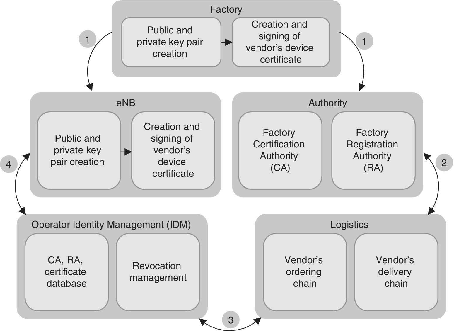
Figure 2.15 The principle of the vendor certificate process
2.5.3 IPsec and Internet Key Exchange (IKE) for LTE Transport Security
The eNB follows the rules established by the Network Domain Security/IP Security (NDS/IPSec) architecture. 3GPP introduces Security Gateways (SEGs) on the borders of security domains to handle the NDS/IPSec traffic. All the NDS/IPsec traffic passes through the SEG before entering or leaving a security domain. The SEGs are responsible for enforcing security policies for the interworking between networks. In this role they also provide the IPsec functions.
It is possible to implement the SEG functionality in dedicated hardware (external SEG) or to integrate it in existing nodes (internal SEG). From the eNB point of view it is not relevant if SEGs are external to the peer entities or integrated, i.e., they are not visible to the eNB. At the eNB side, the IPSec function is integrated into the eNB. Therefore, the eNB represents a security domain of its own and can act as an SEG.
The following logical interfaces can be protected by means of IPSec: S1_U i/f (user data transport, or U‐plane, between the eNB and S‐GW via GTP‐U tunnelling), S1_MME i/f (signalling transport, or C‐plane, between the eNB and MME via the S1AP protocol), X2_U i/f (user data transport, or U‐plane, between eNB nodes during handover via GTP‐U tunnelling), X2_C i/f (signalling transport, or C‐plane, between eNB nodes via the X2AP protocol), O&M i/f (transport of Operations and Maintenance, i.e., O&M data, or M‐plane, between the eNB and O&M system), and ToP i/f (transport of Timing over Packet (ToP) synchronization data, or S‐plane, between the eNB and ToP Master). Figure 2.16 depicts the eNB protocol stacks with the embedded IPSec layer.
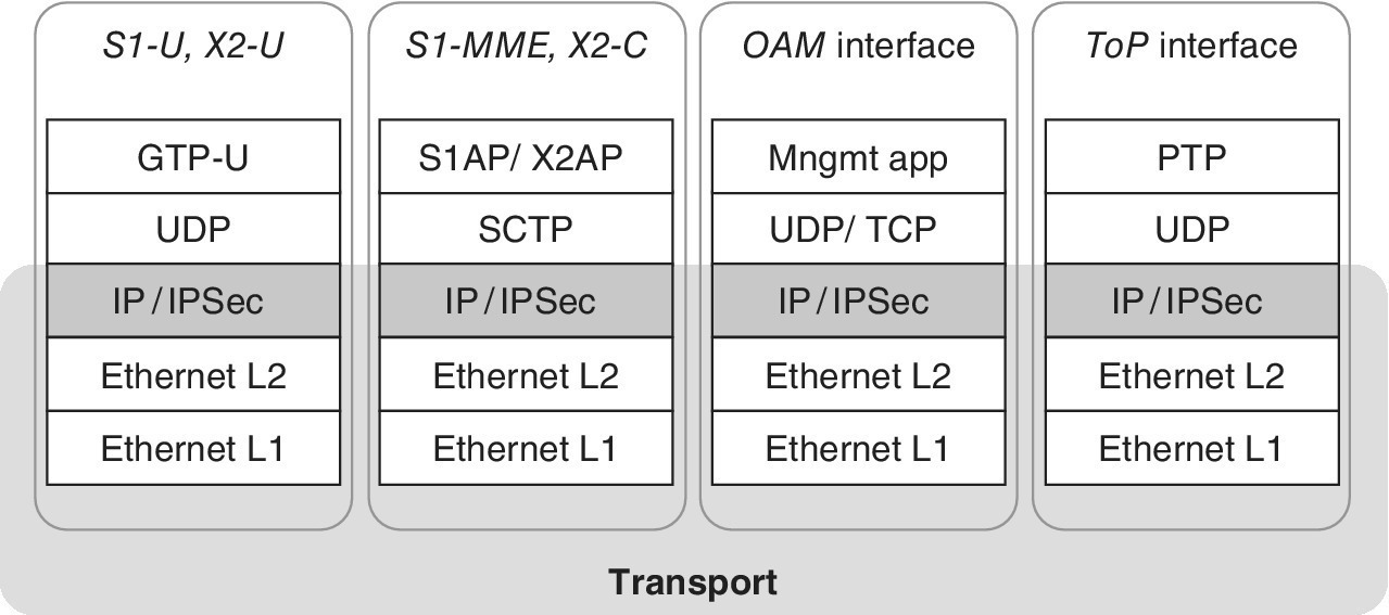
Figure 2.16 The eNB protocol stacks with embedded IPSec layer
2.5.4 Traffic Filtering
2.5.4.1 Firewall
It is possible to have the eNB element support a firewall function with the capabilities to ingress IP packet filtering, ingress rate limiting, egress rate limiting, and to contain DoS countermeasures.
2.5.4.2 Filtering for Site Support Equipment
The eNB may provide access to site support equipment (e.g. battery backup units) via additional Ethernet interfaces. Typically, this type of IP‐based equipment does not provide its own IP packet filter or firewall. Thus, the site support equipment would be directly accessible if there were no packet filter at the eNB side. Therefore, the eNB provides an IP packet filter service that protects the site support equipment from harmful network traffic, and also protects the network from unintended traffic via this interface.
2.5.5 LTE Radio Interface Security
The following sections summarize information about the key hierarchy and the Key Derivation Function (KDF) as a part of the Access Stratum (AS) protection. The key derivation is relevant for normal operation, i.e., call establish and further in the case of a handover (i.e., inter eNB handover). A more detailed description of the LTE security can be found in Ref. [65].
2.5.5.1 Key Hierarchy
Figure 2.17 depicts the LTE key hierarchy concept. It presents the EPS key hierarchy which is valid for steady state when no handover takes place. Nodes are represented by frames, and keys are represented by boxes. An arrow represents a KDF. If a key is derived at one node and transmitted to another, then its corresponding box is located on the border of the frames which corresponds to the involved nodes.
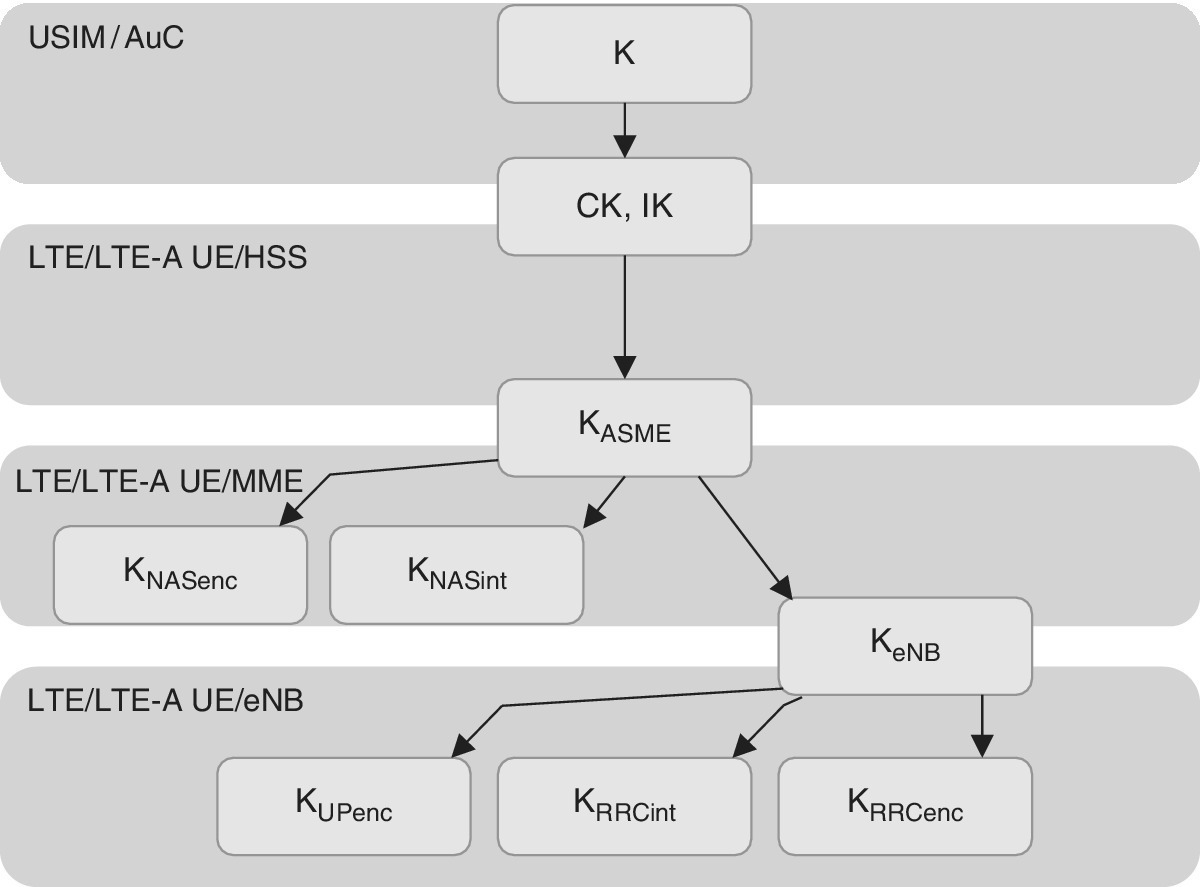
Figure 2.17 LTE Key hierarchy concept
The part of the key hierarchy which is known to the eNB is called the eNB key hierarchy. It comprises all AS keys, i.e., an AS base key KeNB, and three AS derived keys which are KUPenc for the UP encryption, KRRCint for the RRC integrity protection and KRRCenc for the RRC encryption.
K is the only permanent key in the LTE network. All other keys are derived on demand via the KDF which is controlled by a key derivation procedure. The existence of a key depends on the state in the following way: (1) K exists always; (2) Non‐Access Stratum (NAS) keys CK, IK, KASME, KNASenc and KNASint exist in the EMM‐Registered stage; (3) AS keys KeNB, KUPenc, KRRCint, and KRRCenc exist in the RRC‐Connected stage.
2.5.5.2 Key Derivation Functions
The key derivation works with a KDF, which for the EPS is a cryptographic hash function with Ky derived from the KDF as a function of Kx and S. Ky calculates a hash with the key Kx from the string S. The hash value becomes the derived key Ky. In this context, Kx is a superior key which is located at a higher level within the hierarchies (besides the handover case which allows the same level). Furthermore, Ky is the derived inferior key whereas S is a concatenation of several substrings and may be classified as follows: (1) Bound, which refers to a string representation of parameters to which Ky will be bound to. Typically, these parameters describe a part of the environment such as the cell identifier, and Ky is only valid while these parameters do not change. (2) Fresh refers to a string representation of parameters which will ensure different ‘fresh’ Ky, also if all other parameters are unchanged. Usually, these parameters are unique for each instant of calculation, such as is the case for random numbers.
A cryptographic hash function provides a result of a fixed size and it is not reversible, i.e., it is not feasible at the current state of the art to derive unknown parameters if the result and the other parameters are known. In particular, it is not feasible to solve Kx even if Ky and S are known.
2.5.5.3 Key Establishment Procedures
There are three basic key establishment procedures. The first procedure refers to the Authentication and Key Agreement (AKA) which establishes CK, IK, and Key for Access Security Management Entity (KASME) in USIM and UE, and the same set is also established in the AuC, Home Subscriber Server (HSS) and MME. The AKA is an NAS procedure and does not have any prerequisites apart from the availability of the permanent key K. Please note that the MME is the Access Security Management Entity (ASME) for the EPS. The second procedure refers to the NAS Security Mode Command (NAS SMC) which establishes the NAS keys KNASenc and KNASint which are required for the NAS message encryption and integrity protection. The NAS SMC is an NAS procedure and needs a valid KASME as a prerequisite. In addition, the NAS SMC activates the NAS security. The third procedure refers to the AS Security Mode Command (AS SMC) which establishes the AS keys, KUPenc, KRRCint and KRRCenc, which are needed for the UP encryption, RRC integrity protection and RRC encryption. The AS SMC is an AS procedure and needs a valid KeNB as a prerequisite. In addition, AS SMC activates the AS security.
The establishment procedure for KeNB depends on case. In the first case, at change to RCC‐Connected, KeNB will be derived in the MME and transmitted to the eNB by the S1AP Initial Context Setup Request message. In the second case, at active intra‐LTE mobility, KeNB will be derived by a procedure which is shared by source eNB and target eNB.
In the case of intra‐LTE handover, the key hierarchy differs temporarily, because the KeNB for the target eNB will be derived from the KeNB of the source eNB.
2.5.5.4 Key Handling in Handover
Figure 2.18 depicts the key handling in handover procedure. The boxes represent keys and the arrows the KDFs. All keys of the same row are derived in a single chain of KDFs starting from an initial KeNB or Next Hop (NH) parameter. These chains are called forward chains.
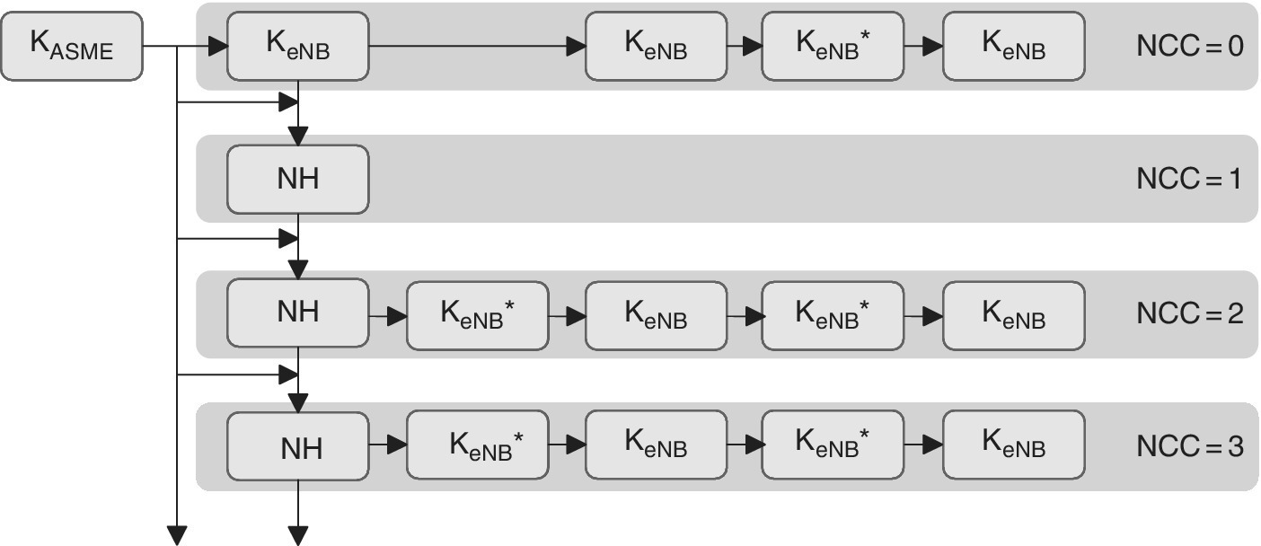
Figure 2.18 Key handling procedure in handover
At the beginning of the context set up, an initial KeNB key is derived from the KASME at the MME. This triggers the first forward chain (referred to as NH Chaining Counter, or NCC, which is set to 0). The initial KeNB key is transmitted to the eNB and becomes its KeNB.
At the handover instance, a transport key KeNB* and finally a fresh target KeNB will be derived. Because the derivation uses a cryptographic hash function, it is not feasible to derive the source KeNB from the fresh target KeNB. Therefore a target eNB cannot expose the security of a source eNB. This is referred to as perfect backwards security.
However, if the derivation happens on one forward chain, i.e., if the KeNB* is derived from the source KeNB, then the target eNB keys are not secret for the source eNB because their derivation is now known. This is true in a recursive manner. Therefore, all keys of the same forward chain which are located to the right hand side of any KeNB are not secret to this key owner. In other words, there is no forward security in these cases.
In order to obtain forward security, the current forward chain has to be terminated and a new one started. This is done by deriving KeNB* from an NH parameter which was derived from KASME and not only from a source KeNB. In the case of the S1 handover, the NH parameter is transported by an S1AP Handover Request message and it applies for that specific handover instance. Therefore, forward security is reached in that handover, and is called forward security after one hop (which may also be referred to as perfect forward security). In the case of the X2 handover, the NH parameter is transported by S1AP Path Switch Acknowledgment and may apply only the next time, but not for this specific handover because the new keys are already determined at this point of time. Therefore, forward security is reached at the next handover. This is called forward security after two hops.
If the NCC reaches its maximum value of 7, it will wrap around and start repeating at the next increment. Please note that 3GPP dictates that the first forward chain is skipped the first time round of NCC after the initial context set up.
2.5.5.5 Security Handling of RRC Connection Reestablishment
If the UE decides to initiate RRC Connection Reestablishment, the following two steps take place regarding the security: (1) The UE transmits an RRC Connection Reestablishment Request message on SRB0 to the cell it selected for requesting the reestablishment. This cell is called the requested cell. The message contains a UE‐Identity to inform the eNB, which was the cell that triggered the RRC reconnection. This cell is called the serving cell. At the RRC Connection Reestablishment, the network adapts its serving cell assumption to the UE. (2) The RRC Connection Reestablishment Request message cannot be authenticated by the PDCP MAC‐I integrity protection, because it transmits across SRB0. Instead, the requested eNB ensures the authentication of the received UE‐Identity by comparing a received authentication code (shortMAC‐I, which is included in the Initial UE‐Identity, or IE) with an authentication code calculated by the network. Each cell enabled to authenticate the RRC reestablishment request applies a dedicated shortMAC‐I because this code is bound to a cell. Now, if the serving cell is controlled by the same eNB as the requested cell, the authentication on the network side is an internal matter of the requested eNB and may happen based on need. If this is not the case, then if the serving cell is controlled by a different eNB as the requested cell, the authentication on the network side is handled between two eNBs, and the calculation of the network’s authentication code takes place on the serving eNB because it requires the RRC integrity protection key (KRRCint) of the serving cell. The comparison of the authentication codes takes place on the requested eNB because it received the shortMAC‐I from the UE, and the calculation of a set of shortMAC‐I and the delivery to another eNB happens in the course of a handover preparation.
The requested cell is controlled by the same eNB as the serving cell if the UE‐Identity is related to the requested eNB, i.e., if the physical cell identity reported by the UE‐Identity belongs to the requested eNB. If the RRC connection reestablishment request is accepted, both UE and eNB refresh their AS key hierarchy in the same manner as happens in the handover procedure from the serving cell to the requested cell, although always with the security algorithms of the serving cell. The possible cases are the same as for the authentication procedure, so as a first option, if the serving cell is controlled by the same eNB as the requested cell, the reestablishment procedure is an eNB internal matter on the network side. In this case, the key refresh happens as for the intra eNB Handover (HO) or, if the requested cell is equal to the serving cell, by intra cell AS security maintenance. As a second option, if the serving cell is controlled by a different eNB from the requested cell, the reestablishment procedure is a matter between two eNBs on the network side. The key refresh happens now as for inter eNB HO according to the HO type which prepared the target cell. In the case of X2 HO, the source eNB needs to calculate a dedicated KeNB* for each cell which will support a reestablishment and to signal it to target eNB in the course of handover preparation. This is similar to the shortMAC‐I provision described above. In the case of S1 HO, the target eNB derives the fresh KeNB from an NH parameter received from MME. Because the NH is independent from the cell, no additional support for reestablishment is needed.
The UE needs to know the NCC parameter for key refresh. It is thus signalled by the RRC Connection Reestablishment message. This message is unprotected, because it transmits across SRB0. If the X2 interface is not protected by IPSec then the X2AP messages including the keys are transferred in plaintext. The SRB1 and all posterior RRC connection reconfiguration procedure bearers will apply the fresh keys immediately.
2.5.6 Authentication and Authorization
In the authentication and key agreement procedure, the HSS generates authentication data and provides it to the MME element processing. There is a challenge–response authentication and key agreement procedure applied between the MME element and LTE‐UE.
The confidentiality and integrity of the signalling is assured via the RRC signalling between LTE‐UE and LTE (E‐UTRAN). On the other hand, there is NAS signalling between LTE‐UE and MME. It should be noted that in the S1 interface signalling, the protection is not LTE‐UE specific, and that it is left optional to implement the protection in S1.
As for the user plane confidentiality, the S1‐U protection is not LTE‐UE specific. There are enhanced network domain security mechanisms applied that are based on IPSec while the protection is optional. The integrity is not protected in S1‐U.
Figure 2.19 depicts an example of a signalling flow for the authentication procedure. In the initial phase of the authentication, the MME element evokes the procedure by sending the IMSI as well as the Serving Network's Identity (SN ID) to the HSS of the home network of the subscriber (2). If the MME does not have information about the IMSI code at this stage, it is requested first from the LTE‐UE (1). The IMSI is delivered over the radio interface in a text format, which means that this procedure should be used only if no other options are available.
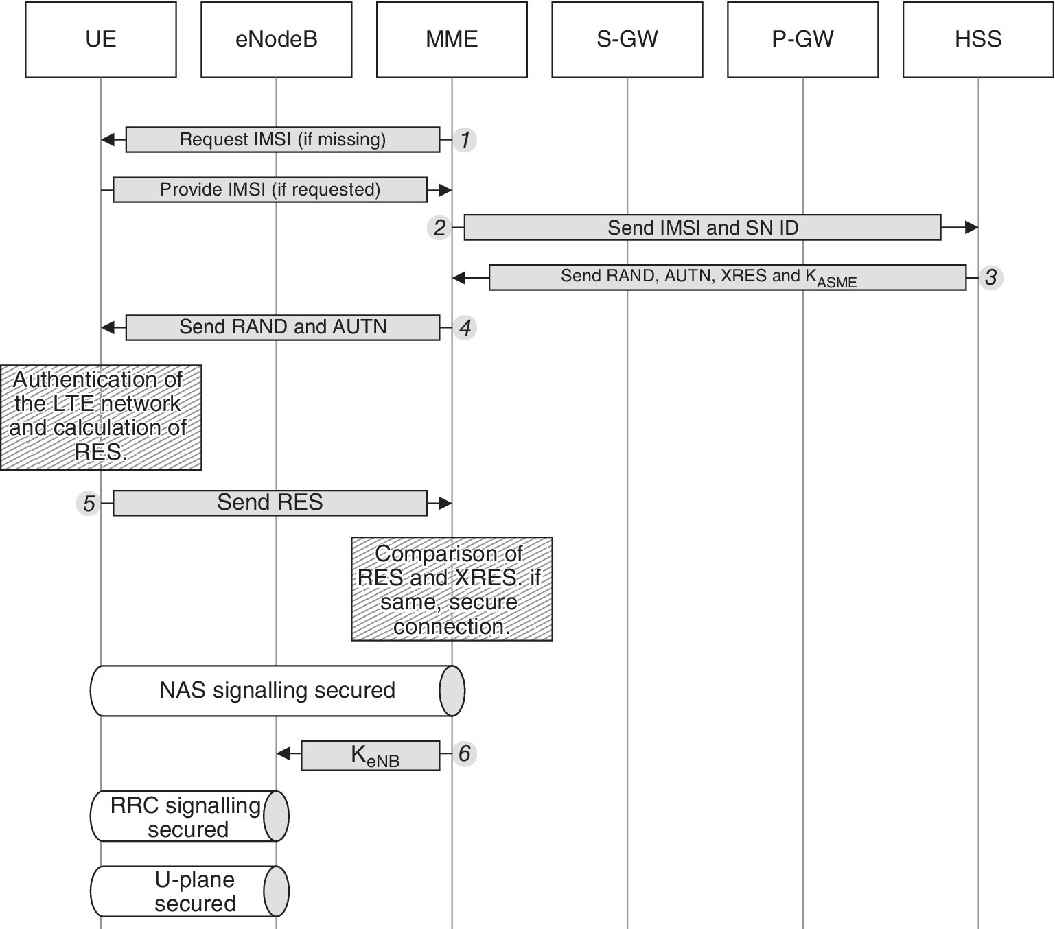
Figure 2.19 The mutual authentication procedure of LTE
After the MME user authentication request to the HSS, the HSS responds with an EPS authentication vector containing RAND, AUTN, XRES and the ASME key (3). Upon the MME receiving this information, it sends the RAND and AUTN to the LTE‐UE (4). Now, the LTE‐UE processes this information and authenticates the network according to the mutual authentication concept. Based on the received information and its own key, the LTE‐UE also calculates a RES and sends it back to the MME (5).
Both the LTE‐UE and the HSS store the same algorithm which is utilized for the calculation of the response with the same inputs. The MME now compares the RES of the LTE‐UE and the XRES that the HSS calculated previously. If they match, the LTE‐UE is authenticated correctly and the NAS signalling will be secured. The eNB key KeNB is calculated and delivered to the eNB in order to encrypt the radio interface for all further signalling and data transmission (6).
The normal procedures that are applied in the 2G and 3G environments for the physical protection of the customer subscription data, charging record data and other confidential information are also utilized in the LTE/SAE environment. The fraud prevention and monitoring applied in the previous generations are applicable also in LTE/SAE.
2.5.7 LTE/SAE Service Security – Case Examples
The LTE/SAE is currently changing the concept of the mobile communications clearly into an all IP environment. Along with its benefits, it also may open potential security holes. The motivations of such illegal activities exploiting the vulnerabilities of the systems include financial, destructive and political reasons, or the aim could also be simply to demonstrate the skills of the hackers.
As an example, the base station equipment has traditionally been well protected in 2G and 3G networks as it has been located physically inside the site with only limited access. Along with the home eNB concept, the equipment may be placed in public areas and homes which exposes the HW for potential malicious intentions. At the same time, the attack methods are getting more sophisticated, and advanced hacking tools are widely available via the Internet. The following sections present examples of the protection mechanisms for this new environment.
2.5.7.1 IPSec
The IPSec together with the PKI are utilized as a standardized LTE security solution. The PKI is applied to authenticate network elements and to authorize network access while the IPSec provides integrity and confidentiality on the transport route for the control and user plane. The IPSec concept is based on the certificate server which is the registration authority within the operator’s infrastructure. It takes care of the certificates which provide secured IPSec routes between the elements via the migrated Security Gateway (SecGW), as shown in Figure 2.20.
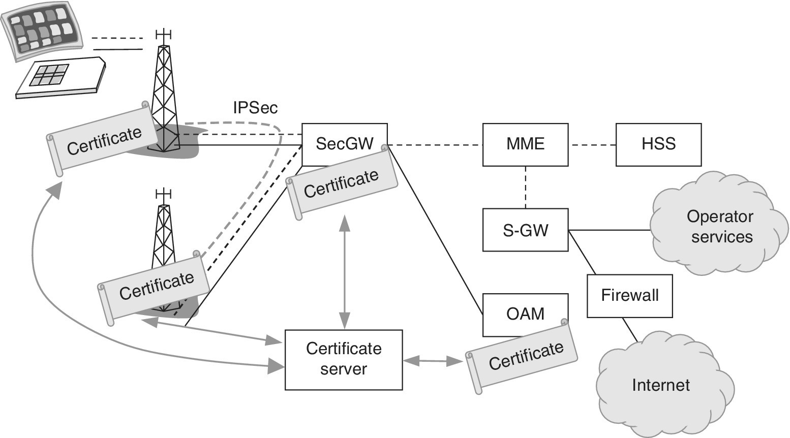
Figure 2.20 The architecture of the combined IPSec and PKI. The light dotted line indicates signalling, and solid line represents user plane data flow. The thick dotted line symbolizes the IPSec tunnel. The communication between SecGW as well as Operations Administration and Maintenance (OAM) can be done via Transport Layer Security (TLS) or Secure HTTP (HTTPS)
Security Gateways with high availability such as Juniper or Cisco are examples of scalable platforms terminating the IPSec traffic from the eNBs and anticipate fast‐growing performance figures for the next few years. Insta Certifier is a PKI platform for issuing and managing digital certificates both for users and machines. It provides Certification Authority (CA) and Registration Authority (RA) functionality which are manageability for very large PKI environments by introducing centralized management of authentication keys with support for scalable revocation and key updates.
The LTE/SAE network elements possess identity and are able to authenticate. There are two kinds of authorities in the security solution. The first one is the Factory Registration Authority, which requests vendor certificates, centralized vendor‐wide CA issues and keeps the certificates in a database. The second one is the Operator’s Certificate Authority which recognizes the vendor’s certificates and authorizes requests. This authority issues and manages operator certificates for the network elements. Figure 2.21 summarizes the SW architecture and interfaces for the PKI solution.
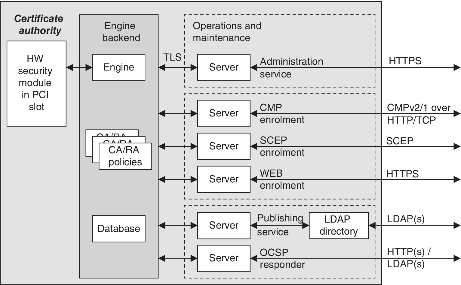
Figure 2.21 The PKI design with the architecture and interfaces
2.5.7.2 IPSec Processing and Security Gateway
The LTE standards define IPSec capability at the eNB level, including the authentication procedure based on X.509 certificates. The support of this functionality is mandatory, but for the trusted networks (considered reliable by the operator), the actual utilization of IPSec is left optional. In practice, the eNB may include both the IPSec and the firewall together with the authentication procedure via the X.509 certificates. The combination of the IPSec and the firewall provides the possibility to integrate the respective firewall rules with the rest of the network management which requires only minimum manual configuration.
In the following scenario, the SecGW is a complementary solution placed alongside the Aggregation Router (AR) with both incoming and outgoing interfaces connected to the AR. The advantage of this scenario is that only a few changes on the existing network are required. Furthermore, the scenario allows the aggregation of all interfaces between the AR and SecGW into one logical link. Once aggregated, various types of traffic can be separated on Layer 2 by defining corresponding Virtual LAN (VLAN) interfaces on the SecGW. This setup provides better flexibility and resilience against single link outages. Figure 2.22 depicts an integration example.
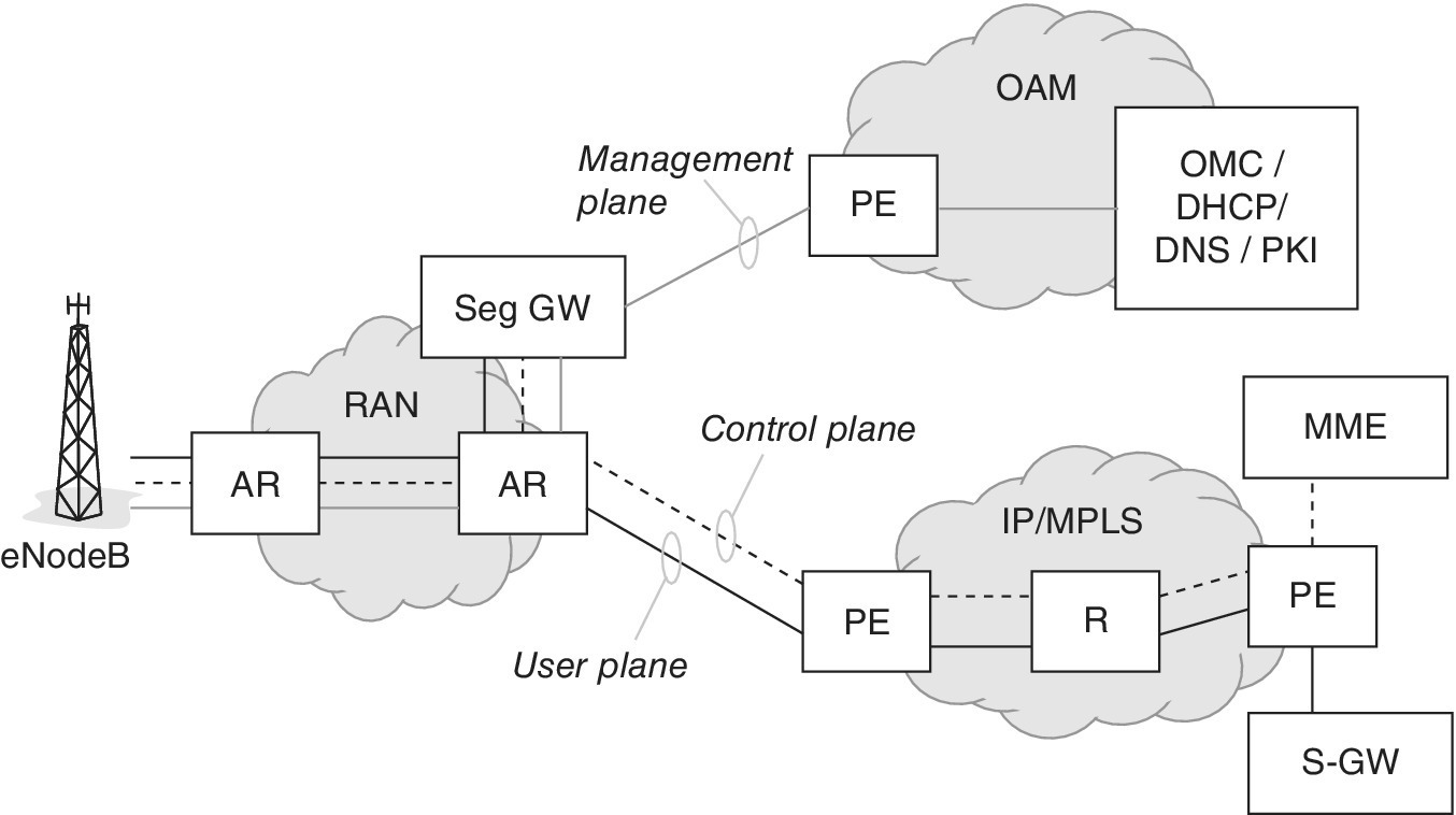
Figure 2.22 An integration example for the gateway attached to the access router
The SecGW may provide several options to achieve traffic separation. The first solution is the use of virtual routers which allows the separation of routing domains into logical entities and separated routing table. Each virtual routing entity handles its directly connected networks and static or dynamic routes. The second option is based on VLANs that are used to separate the traffic within physical links. All security concepts work with physical and logical sub‐interfaces. The third option is the definition of dedicated security zones as shown in Figure 2.23. These zones are used to logically separate network areas and provide more granular traffic filtering and traffic control by defining access control and filter policies.
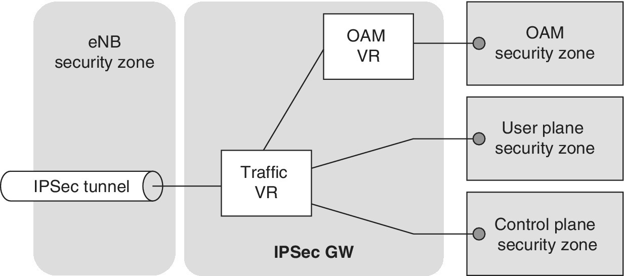
Figure 2.23 The security zone principle
The Virtual Private Network (VPN) design of the SegGW can be based either on a single tunnel set up, or a multiple tunnel set up. For the single tunnel set up, the traffic of all planes is encrypted with the same encryption set, i.e., either a single IKE SA or a single IP‐SEC SA. The set up can be based on the dedicated tunnel interface per eNB, which means that each eNB has its own tunnel interface on the SecGW. The set up can also be based on the shared tunnel interface, which means that all the eNBs share one tunnel interface on the SecGW.
For the multiple tunnel set up, the traffic for each plane is encrypted with different encryption sets (1 IKE‐SA/3 IP‐SEC SA). The multiple tunnel set up can be based on the dedicated tunnel interfaces per eNB, or on the shared tunnel interfaces.
2.5.7.3 Single Tunnel with Dedicated Tunnel Interfaces
The benefit of this solution is that it provides a persistent tunnel interface per eNB. All routes to one eNB point to the same interface, which makes the design easier. The third benefit is the small amount of Security Associations (SAs). As a drawback, the solution requires a large amount of tunnel interfaces.
2.5.7.4 Single Tunnel with Shared Tunnel Interfaces
The benefit of this design is that only one tunnel interface is required per chassis. The eNB inner routes can be aggregated on the SecGW. As in the previous case, only a small amount of security associations is needed. The drawback of this solution is that the scalability of the design is linked to the IP address concept.
2.5.7.5 Multiple Tunnels with Dedicated Tunnel Interfaces
The benefit of this solution is related to the dedicated tunnel interfaces per plane per eNB. A drawback is that three tunnel interfaces per eNB are required. Another issue is the larger amount of security associations. Due to these drawbacks, this is the least feasible solution in practice.
2.5.7.6 Multiple Tunnels with Shared Tunnel Interfaces
The benefit of this solution is that only one tunnel interface per plane per chassis is needed. In addition, the eNB inner routes can be aggregated on the SecGW. As drawbacks, larger amounts of security associations are required. Also, an additional IP network for the VPN next‐hop table is required if the eNB inner routes cannot be aggregated per plane. Furthermore, the scalability is limited by the IP address concept.
2.5.8 Multimedia Broadcast and Multicast Service (MBMS) and enhanced MBMS (eMBMS)
2.5.8.1 General
The MBMS offers broadcast and multicast user services over cellular networks. The MBMS specifications define four types of services: (1) streaming services; (2) file download services; (3) carousel services; and (4) television services.
The MBMS is suitable in many environments for data reception. It applies to consumer use cases like audio/video contents streaming as well as to M2M use cases like a car’s navigation system map updates. Furthermore, the MBMS contents delivery can be varied based on location and device type.
The MBMS introduces a Point‐to‐Multipoint (PTM) service into 3GPP 2G and 3G systems. Originally standardized in 3GPP Rel. 6, the enhanced MBMS (eMBMS) via LTE provides solutions for delivering a variety of broadcast/multicast contents. One of the requirements of the MBMS User Service is to be able to securely transmit data to a given set of users. In order to achieve this, there needs to be a method of authentication, key distribution and data protection for an MBMS User Service as defined in 3GPP TS 33.246 (Rel 12). This means that MBMS security is specified to protect MBMS User Services, and it is independent of whether multicast or broadcast mode is used. The security refers to the protected delivery and utilization of the contents, e.g., by limiting the access to closed channels for authorized user groups (pay channels, special groups). In a wider context, security also may refer to the assurance of the contents delivery. As the MBMS is based on downlink data there is no need for a separate return channel so all the contents are broadcasted/multicasted without acknowledging the success of the reception (which is the benefit of MBMS as it does not reserve additional resources per user). The MBMS includes a Forward Error Correction (FEC) mechanism and file repair functionality. The level of these functionalities is parametrized, and the feasible selection of the values is one of the optimization tasks of the MNO.
The delivery method of MBMS leads to different challenges for securing the connection and contents compared to the security of Point‐to‐Point (PTP) services, like eavesdropping on non‐public contents over a wide service area, or a valid subscriber may circumvent the security solution, e.g., by publishing the decryption keys enabling non‐subscribers to consume broadcast content.
The MBMS contains two data transmission modes which are broadcast mode and multicast mode. The main principle of the MBMS broadcast service is that it is a unidirectional PTM service. This service delivers the data stream from the network to all capable 3GPP User Equipment (UE) within the respective broadcast service area. In this way, broadcast services can be received by all the users within the service area if they have activated the reception of the MBMS service in their UE.
The MBMS utilizes the radio and core network resources in an optimal way as the data is transmitted over the common radio channel, and it is flexible for the data rate. The transmission thus adapts to variable radio access network capabilities as well as for varying availability of resources. The adaptation happens by adjusting the MBMS streaming bit rate accordingly. As there is no return channel present for error recovery purposes for the broadcast mode, the correct reception of MBMS cannot be guaranteed. Nevertheless, as FEC functionality is incorporated, the receiver may be able to recognize data loss and try to recover the data according to the FEC principles.
In addition to the broadcast mode, MBMS also contains the multicast mode. In this case, the data is transmitted over a unidirectional PTM connection from a server to multiple subscribers that are present in the multicast service area. Compared to the broadcast mode, multicast services can only be received by users that have subscribed to a certain multicast service and have joined the multicast group associated with the specific service. The basic principle is that the broadcast mode is open by default whereas the multicast mode typically requires a subscription to multicast groups prior to the user joining the multicast group.
The MBMS user services can be divided into three groups which are download delivery, streaming delivery and carousel service. The download delivery service delivers files (binary data) via the MBMS bearer. The UE, i.e., the MBMS client activates the related application and consumes the received data. In this solution, it is important that the data is received in a reliable way which makes the FEC method essential.
The streaming delivery service provides a continuous stream of, e.g., audio and video. Supplementary information via text or still images can also be important in this service. This provides an interactive way of using additional services. As an example, the received text may include web links that lead to additional information related to the contents. In this scenario, the link received via broadcast delivery, the user can access the additional content simply by clicking the link, and by creating a dedicated PTP via any available access method.
The carousel service is able to repeat a broadcast transmission of, e.g., a file or set of files repeatedly in such a way that the customer can receive the same contents every now and then. This can be, e.g., an update to the map data of location‐based service. The carousel service combines aspects of the download and streaming services.
In order to provide MBMS bearer services, cellular network elements like GGSN, SGSN, RNC or Base Station Controller (BSC) take part in various MBMS related functionalities. Figure 2.24 shows the reference architecture of MBMS.
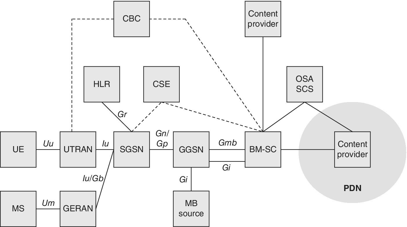
Figure 2.24 The MBMS reference architecture.
Source: Reprinted from [38] by courtesy of ETSI
In practice, the basic MBMS service has not taken off commercially. The upgraded eMBMS architecture meant for the LTE networks as defined in 3GPP Rel 9 and beyond is depicted in Figure 2.25. In this solution, the Broadcast Multicast Service Center (BM‐SC) is connected to the MBMS gateway, which in turn, connects directly to eNB elements for the user plane contents transfer, and via MME for the initial PTP signalling.
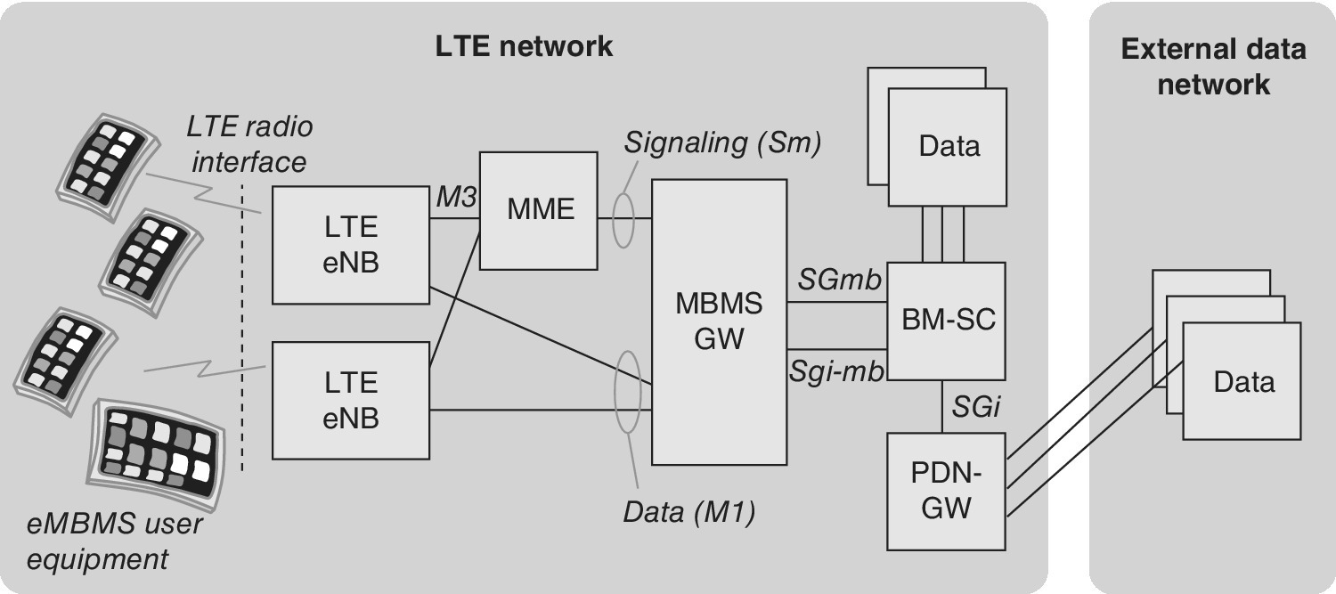
Figure 2.25 The eMBMS reference architecture.
Source: Reprinted from [38] by courtesy of ETSI
The BM‐SC provides functions for the MBMS user (both MBMS and eMBMS) service provisioning and delivery. It may serve as an entry point for content provider MBMS transmissions, used to authorize and initiate MBMS bearer services within the Public Land Mobile Network (PLMN) and can be used to schedule and deliver MBMS transmissions. The BM‐SC shall be able to generate charging records for content provider transmitted data, and supply the GGSN with transport associated parameters such as QoS and MBMS service area in order to initiate and terminate MBMS bearer resources for following transmission of MBMS data. The BM‐SC also needs to accept content from external sources and transmit it using error resilient schemes, schedule MBMS session retransmissions, and label each MBMS session with an MBMS Session Identifier to allow the UE to distinguish the MBMS session retransmissions. Furthermore, the BM‐SC provides service announcements for multicast and broadcast MBMS user services, and transfers data on separate MBMS bearer services for 2G or 3G coverage, typically having different QoS.
The UE supports functions for the activation and deactivation of the MBMS bearer service and security functions as appropriate for MBMS. The UE should be able to receive MBMS user service announcements, paging information (non‐MBMS specific) or support simultaneous services. The MBMS Session Identifier contained in the notification to the UE shall enable the UE to decide whether it ignores the forthcoming transmissions of the MBMS session.
The UTRAN/GERAN network is responsible for efficiently delivering MBMS data to the designated MBMS service area. Efficient delivery of MBMS data in multicast mode may require specific mechanisms in the UTRAN/GERAN. Intra‐RNC/BSC, inter‐RNC/BSC mobility of MBMS receivers shall be supported. The UTRAN/GERAN shall be able to transmit MBMS user service announcements, paging information and support other services parallel to MBMS.
The SGSN within the MBMS architecture performs user individual MBMS bearer service control functions and provides MBMS transmissions to UTRAN/GERAN. The SGSN provides support for intra‐SGSN and inter‐SGSN mobility procedures. The SGSN generates charging data per multicast MBMS bearer service per user. The SGSN is also able to establish Iu bearers (SGSN‐UTRAN signalling) and Gn bearers (SGSN‐GGSN signalling) shared by various users on demand when data is transferred to the users. This should be done upon notification from the GGSN.
The GGSN within the basic MBMS architecture serves as an entry point for IP multicast traffic as MBMS data. Upon notification from the BM‐SC the GGSN shall be able to request the establishment of a bearer plane for a broadcast or multicast MBMS transmission. Furthermore, upon BM‐SC notification the GGSN shall be able to tear down the established bearer plane. Bearer plane establishment for multicast services is carried out towards those SGSNs that have requested to receive transmissions for the specific multicast MBMS bearer service. The GGSN shall be able to receive IP multicast traffic from BM‐SC and to route this data to the proper GPRS Tunnelling Protocol (GTP) tunnels set up as part of the MBMS bearer service. The GGSN may also receive IP multicast traffic from other sources than the BM‐SC. However, the MBMS bearers are not used to forward this traffic from non‐BM‐SC sources. The GGSN shall collect the charging data.
2.5.8.2 Solutions for MBMS Security
The LTE network attach/context activation procedure limits the possibilities of non‐LTE subscribers to misuse the contents. For example, television type of contents delivery, protecting a potential separate, content‐related decryption key publishing might require, e.g., frequent updating of decryption keys in a non‐predictable manner while making efficient use of the radio network. The open contents do not basically require specific secure technologies apart from the normal network access procedures. The consumption of MBMS contents can thus be done via a streaming app. Nevertheless, if the contents need to be limited based on, e.g., subscription, time and quality, the standard MBMS procedures might not suffice, but additional solutions could be used, like more thorough app‐based management of contents consumption. It should be noted, though, that the pure software might be vulnerable to attacks.
When selecting the proper security mechanism for MBMS contents delivery and utilization, the key task is to balance fluent user experience and adequate protection level. The LTE MBMS provides a highly efficient way to deliver broadcast and multicast contents over the designed service area by maintaining the network load under control as the amount of receiving customers does not increase the data transmission. Straightforward solutions for protecting the contents are based on application level reception of the contents as the customer can be authenticated and authorized for the subscription via the mobile network’s procedures. Nevertheless, additional and more precise protection of the contents per customer (e.g., pay‐TV during certain hours/occasions like a football event) may benefit from more sophisticated methods like the TEE. The following sections summarize some of the most logical security solutions for MBMS.
2.5.8.3 Security Principles
The Stage 1 requirements for MBMS include security aspects such as the following, according to 3GPP TS 22.146, Release 12. Only those users who are entitled to receive a specific MBMS service may do so. It should be possible to choose whether a given MBMS service is to be delivered with or without ensured group security. If a terminal supports MBMS, then it shall support UICC based key management and all the functions and interfaces required for it. In addition, Mobile Equipment (ME) key management shall be supported. If the UICC is capable of MBMS key management, ME key management shall not be activated; otherwise, ME‐based key management is applied.
The Stage 2 requirements include, according to 3GPP TS 22.246 (Release 12), rules dictating that any user‐modifiable MBMS service data (e.g. storage of deliveries in the UE, data type and format specific behaviours) shall only be modified by the authenticated user. Stage 3 details further the MBMS security as described in 3GPP TS 33.246 (Release 12), section 4. According to it, the MBMS User Service must securely transmit data to a given set of users by using methods for authentication, key distribution and data protection. This means that the MBMS security is specified to protect the MBMS User Services, and it is independent of whether multicast or broadcast mode is used.
In addition to ME and UICC‐based key management that are based on the 3GPP specifications, the eMBMS could also be combined with other solutions that provide additional layers of security, such as TEE or OMA DRM.
2.5.8.4 ME‐based Security
The ME procedure as described in 3GPP TS 33.246 relies on the security of the LTE infrastructure, see Figure 2.26.
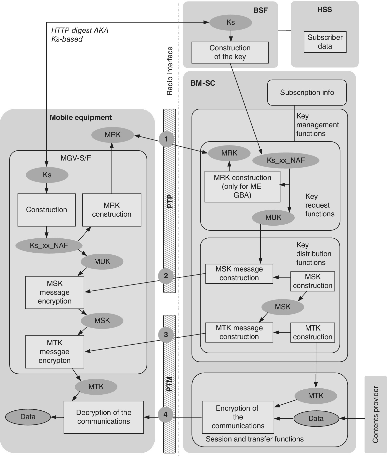
Figure 2.26 The elements and key management procedures for ME‐based eMBMS security as described in 3GPP TS 33.246. The events in the radio interface are the following: (1) HTTP Digest authentication with the MRK key; (2) MIKEY MSK key distribution which is protected with the MUK key; (3) MIKEY MTK key distribution which is protected by the MSK key; and (4) user data which is protected via the MTK key.
Source: Reprinted from [38] by courtesy of ETSI
2.5.8.5 UICC‐based Security
The UICC functions for the establishment of the LTE connection which in turn provides the eMBMS utilization as any other LTE service. When more detailed contents security procedures for the eMBMS are done via UICC, it may require additional development efforts such as UICC Operating System support for key derivation functionality, Generic Bootstrap Architecture (GBA) support, support for eMBMS‐specific functionalities like the Authenticate command, and support of odd values of instruction bytes (ODD INS bytes). In addition, compliance with the ETSI secure messaging requirements is needed.
2.5.8.6 TEE‐based Security
The TEE is based on Trusted Applets within the Secure World, which is isolated from the Normal World. The secure services, or trustlets can run within the TEE which protects the contents and is separated from the general operating system, that is, Rich OS, which can be for example Android. Trustlets can be provisioned and managed over the air via TEE‐TSM (Trusted Service Manager). The TEE is described in more detailed in section 6.3.3.
2.5.8.7 Digital Rights Management (DRM)
DRM refers to a set of methods for access control technologies for copy protection designed/applied by hardware and software manufacturers, publishers, copyright holders and any other party wanting to control the use of digital content and devices. The early DRM software was intended to control copying while the more mature variants of DRM aim to control executing, viewing, copying, printing and altering of works or devices.
The key benefit of DRM is that it provides an additional level of protection to prevent unauthorized sharing. Its weakness is that with time and sufficient efforts, there may be ways to bypass it. Also, user experience may be limited as DRM can sometimes be non‐optimal for purchase portability between devices.
As for feasible DRM solutions, the Open Mobile Alliance (OMA) Mobile Broadcast Services Enabler Suite (BCAST) is an open global specification for mobile television and on‐demand video services which can be adapted to any IP‐based mobile and Point‐to‐Point (PTP) content delivery technology, end‐to‐end service and content protection based on the OMA BCAST smartcard and OMA DRM profile. Designed to support broadcast technologies such as DVB‐H, 3GPP MBMS, 3GPP2 mobile unicast streaming systems and ATSC‐M/H, the OMA BCAST 1.0 relies on the XML structure to specify a set of features such as electronic service guide, file and stream delivery, service and content protection using the smartcard or DRM profiles, terminal and service provisioning, as well as interactivity and notifications.
2.5.8.8 Comparison of Security Options
As reasoned in the previous section, the eMBMS may be used as standalone solution with its own integrated security, or with an additional security layer. Table 2.2 summarizes some pros and cons of the security options presented previously.
Table 2.2 Comparison of MBMS security solutions
| App‐based | TEE | DRM | Terminal‐based | UICC‐based | |
| Principle | Streaming and contents selection via pre‐installed or downloaded software | Trusted applet within TEE’s secure world which is based on TSM | DRM via various methods | Embedded functionality within the device | Software embedded into UICC or embedded secure element |
| Pros | Straightforward to develop and deploy | Good protection for streaming and displaying | Set of established methods | Standard solution for mobile device hardware | Provides highest security level via tamper‐resistant element |
| Cons | Security level and functionality may be limited (e.g., only for initial access) | Limited terminal availability and networks supporting TEE/TSM | Possibly limited end‐user experience | Terminal/chipset availability supporting eMBMS | May require OS enhancements and support for key derivation, GBA and eMBMS authenticate command |
2.5.8.9 MBMS Error Correction
The File Transport over Unidirectional Transport (FLUTE) is a transport protocol that is designed to deliver files from a set of senders to a set of receivers over unidirectional systems. The FLUTE was developed by the Internet Engineering Task Force (IETF), and it serves for the file transmission over wireless and point‐to‐multipoint systems, such as eMBMS. The FLUTE is specified on top of the Asynchronous Layered Coding (ALC) protocol instantiation of the Layered Coding Transport (LCT) building block. The FLUTE uses the UDP/IP layer and is transported via respective packets. It is thus independent of the IP version and underlying link layers. The FLUTE uses a File Delivery Table (FDT) to provide a dynamic index of files. Optionally a Forward Error Correction (FEC) can be used for improving the reliability of the downlink data transfer. A Congestion Control (CC) can also be optionally selected in order to enable Internet friendly bandwidth use. See Figure 2.27.
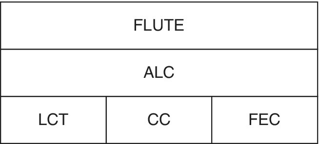
Figure 2.27 The protocol layers of FLUTE
2.5.8.10 MBMS Charging
According to the specifications for the charging, broadcast and multicast modes as stated in 3GPP TS22.146 (Rel. 12), it shall be possible to collect charging information for the transmission of broadcast services to enable billing of broadcast services providers, such as billing third parties for advertising. The charging information therefore needs to be secure to ensure correct billing. Some examples of types of charging information are the broadcast usage duration broadcast volume of contents, multicast session duration and time when joining and leaving a multicast subscription group. Furthermore, the charging information may capture the duration of membership to a multicast subscription group, and multicast session volume of contents. It is also possible to collect subscriber’s charging information in home networks and when roaming based on the security procedures for the key management, in order to bill based on the reception of broadcast data on a per‐broadcast service basis. Furthermore, the MBMS User Service shall support charging mechanisms as stated in 3GPP TS 22.246 (Rel 12), which describe the charging on a subscription basis as well as the charging for keys that allow the user access to the data.
2.6 Security Aspects of Other Networks
2.6.1 CDMA (IS‐95)
Interim Standard 95 (IS‐95) is a US‐driven digital CDMA cellular system, known also as cdmaOne or TIA‐EIA‐95. IS‐95 belongs to the 2G cellular systems. The IS‐95‐based networks are utilized widely in North America, and it is also supported in various areas outside the United States. The first specification set for the system was called IS‐95A, and the enhanced specification IS‐95B was released later. The system is meant for voice and data services. The data transfer rate for IS‐95A is up to 14.4 kbps, and for IS‐95B up to 115 kbps.
IS‐95 is based on Direct Sequence Spread Spectrum (DSSS) technology. It functions efficiently to hide the signal in the radio spectrum below the thermal noise level, which makes the detection and jamming of the signal challenging; in fact, for that reason, the technique was first utilized in the military environment well before its commercial phase.
The basic CDMA system, i.e., IS‐95A and IS‐95B, later evolved towards the 3G system. The resulting 3G system is called commercially as CDMA2000. This system includes CDMA2000 1x and CDMA2000 1x EV‐DO (Evolution Data Only/Data Optimized). There has also been a theoretical variant called CDMA2000 1x EV‐DV (Evolution Data and Voice).
CDMA is both a radio interface definition as well as an access method for cellular systems. It is based on the separation of users by different codes, dedicated for each user within the same area. To complement the whole network system, the core part is based on the Time Division Multiple Access (TDMA) principles in a similar manner as in the GSM system. There are thus considerable similarities in the practical solutions of the upper layers to the air interface, including Radio Resource Management (RRM) and Mobility Management (MM).
The idea of the DSSS is to multiply the data stream with another one that is using a considerably higher data rate. This spreading code widens the frequency bandwidth for the actual data transmission. The original data stream can be detected when the very same spreading code is applied in the reconstruction of the data. As the spreading codes and data stream of a certain user is seen as background noise to outsiders, it is thus possible to utilize the same, wide frequency band for several users in such a way that they are not interfered by the others. This phenomenon can be compared with a cocktail party where participants speak in different languages (comparable to scrambling codes). The participants interpret the unknown languages merely as background noise, and even if the noise level rises, the ones that understand a common language can interpret the respective contents from far away. The correlation of the codes for scrambling and unscrambling thus provides the possibility to apply multiple access entries in the system.
Via spread spectrum techniques like the DSSS, CDMA utilizes the same, relatively wide frequency band for sharing the data transmission for all the users located in the area. The essential parts for making the CDMA system work are the transmit power control and error correction codes. There are also other functionalities which increase the performance of the system, like the RAKE receiver for combining multi‐path propagated signal components of the same signal, variable data rates for data transmission and voice service, and a soft handoff mechanism. The complete set of different functionalities provides the possibility to lower the requirements of the carrier per interference (C/I) level which in turn enhances the spectral efficiency.
Each IS‐95 carrier contains logical channels. As everything is transmitted and received within the same frequency band of the carrier, these channels are separated from each other by a variety of spreading codes. When the signal is processed, it goes through several steps including the coding itself and interleaving, which results in the symbols to be transmitted over the radio interface. In order to do this, the symbols are modulated with Walsh codes.
The security of the IS‐95 radio interface is based on the CDMA signal itself (being below the noise level), and Cellular Authentication and Voice Encryption (CAVE) algorithm [56]. The CAVE is based on a 64‐bit A‐key which is used together with an Electronic Serial Number (ESN) and a random number in order to generate a 128‐bit long Shared Secret Data (SSD). Furthermore, the SSD is divided into two 64‐bit blocks from which block A is meant for authentication and block B for encryption. The principle uses a challenge–response technique for the authentication of the subscription while the random number is used to create a session key for the encryption of voice and data traffic. Ref. [57] claims that there is an inherent signal feature on the plaintext in the IS‐95 CDMA system, and has been able to prove the functioning of a ciphertext‐only attack method to solve the initial phase of the key sequence by eavesdropping on a 20 ms ciphertext frame. The described attack method is based on the exploitation of the linear relations between the key sequence and the state of the long code generator which has resulted in an algorithm for decoding the private mask, showing that the voice encryption of IS‐95 system is unsecure against ciphertext‐only attack.
2.6.2 CDMA2000
CDMA2000, which also is known as International Mobile Telecommunications‐Multi Carrier (IMT‐MC), belongs to the 3G cellular systems together, e.g., with UMTS. CDMA2000 standards consist of CDMA2000 1X, CDMA2000 EV‐DO Rev. 0, CDMA2000 EV‐DO Rev. A, and CDMA2000 EV‐DO Rev. B. These variants comply with the ITU IMT‐2000 requirements, and furthermore, CDMA2000 is backwards‐compatible with the North American 2G system, IS‐95. In the United States, CDMA2000 is a registered trademark of the Telecommunications Industry Association (TIA). The security risks for CDMA2000 are comparable with the ones described for UMTS.
The CDMA2000 1x EV‐DO, often abbreviated as EV‐DO or EV, is a telecommunications standard for the wireless transmission of data through radio signals, typically for broadband Internet access. It uses multiplexing techniques including CDMA as well as TDMA to maximize both individual users’ throughput and the overall system throughput. It is standardized by the 3GPP2 as part of the CDMA2000 family of standards and has been adopted by many mobile phone service providers around the world – particularly by the ones in the previous CDMA network. It is also used on the Globalstar satellite phone network.
The radio interface of the CDMA2000 system differs from the one used in UMTS. Nevertheless, the core network has synergies between these and other systems. As an example, the TIA packet core network was specified by TIA TR45.6., and the work was based strongly on IETF solutions [7].
CDMA2000 belongs to the ITU IMT‐2000 and complies thus with ITU‐defined 3G standards. CDMA2000 is based on the CDMA IS‐95 system providing an evolution path. The other entity specifying CDMA2000 is the 3GPP2, which assures that the core solution is compatible with 3GPP systems.
Ref. [58] summarizes the principles of CDMA2000 for the protection of system resources against unauthorized use. The security of the system is based on the terminal authentication which needs to prevent fraudulent use of the network. There is thus a proof of subscription identity used, proof of sender identity and message integrity. In addition, CDMA2000 includes network authentication, comparable to the UMTS mutual authentication principle, which prevents false base station attacks on user information. The successful authentication is a prerequisite for authorization, and the service access rights subscription data are passed from the home system, i.e., Home Location Register (HLR) or Authentication, Authorization and Accounting (AAA) to the serving system.
IS‐2000/C.S0001‐0005 is based on symmetric keys for the encryption. The system relies on root a authentication key for the security association, and the session keys are derived from the root key during authentication. IS‐856/C.S0024, in turn, is based on a public‐key agreement to establish airlink session keys. It uses symmetric keys for RADIUS authentication.
Ref. [58] further summarizes the procedures for IS‐2000 authentication which is based on the challenge–response principle. For Rev B and earlier variants, the authentication is based on IS‐95 for legacy reasons whereas for Rev C and later, the AKA principle is used for the authentication in a similar fashion as it is deployed in UMTS. In addition, the latter variants may use optionally a User Identity Module (UIM) authentication procedure for proving presence of a valid UIM, preventing rogue shell attacks. CDMA2000 also includes checking the message integrity, based on the keyed SHA‐1 hash of the message contents. Furthermore, there is a Cryptosync based on time and other data defined in order to prevent replay attacks.
e IS‐2000 also contains identity privacy via the TMSI. For the user data privacy, IS‐2000‐B and later variants rely on the 128‐bit Rijndael algorithm (AES). The IS‐2000 encryption uses 64‐bit keys from legacy authentication, and 128‐bit keys from AKA.
Ref. [59] has concluded that the security mechanisms in CDMA2000 represent a major improvement over the 2G mechanisms. The system provides an efficient one‐pass challenge–response mechanism including mutual authentication that tackles the threat of false base station attacks. Furthermore, the confidentiality algorithm of CDMA2000 is noted to be stronger than the one used in 2G systems, and Ref. [59] also claims that it is more efficient than the one used in the 3GPP UMTS system.
2.6.3 Broadcast Systems
The broadcast systems are typically used for delivering radio and television programmes to the public. The security of the systems is related to the assurance of the confidentiality in the closed channel delivery. It can be related to, e.g., pay‐TV contents that need to be purchased prior to their consumption.
The global distribution of digital television deployments is based on mainly the following main standards: Digital Video Broadcasting (DVB) (Europe, Africa, Asia and Australia), Advanced Television Systems Committee (ATSC) (North America), Terrestrial Integrated Services Digital Broadcasting (ISDB‐T) (South America, Japan) and Digital Terrestrial Multimedia Broadcast (DTMB) (China). The Digital Rights Management (DRM) and Conditional Access (CA) function as a basis for the controlled programme delivery and for providing security for terrestrial television and radiobroadcast networks.
In addition to the PTP links that can be utilized for audio and video streaming reception in the mobile communication environment, the mobile networks may contain built‐in functionalities for providing broadcast type of services. Examples of such services are Cell Broadcast (CB) and MBMS. Furthermore, the CB and MBMS (including the evolved version eMBMS) can be utilized in the normal information delivery as well as a base for warning systems.
2.6.4 Satellite Systems
As Ref. [16] states about modern Satellite Communications (SATCOM), proper protection of satellite systems for privacy and security is increasingly important especially for special environments such as military applications. At present, though, the securing is typically done merely via upper layer protocols as can be interpreted from [22,23]. Ref. [16] furthermore concludes that there may be alternatives for multi‐beam secure satellite communications such as the ones through physical layer security techniques which refers to joint power control and beamforming schemes and related individual secrecy rate constraints.
2.6.5 Terrestrial Trunked Radio (TETRA)
TETRA is a radio system meant for professional, global use which is aimed at police, fire brigades, defence forces, rescue departments and other entities requiring safe and closed communication for emergency‐type of operations [7]. The TETRA is an open standard developed by ETSI. The main purpose of the TETRA standard is to define a series of open interfaces, as well as services and facilities, in sufficient detail to enable independent manufacturers to develop infrastructure and terminal products that would fully interoperate with each other as well as meet the needs of traditional Private Mobile Radio (PMR) user organizations. The TETRA has already been deployed in many regions and nations within and outside Europe [7].
The PMR networks are highly needed because public networks cannot adequately guarantee required RF coverage or Grade of Service (GoS) during emergency situations. In addition to the basic communications, public networks cannot typically provide specialized voice services such as fast call set up, Direct Mode Operation (DMO) and high levels of secure encryption for voice and data.
The original TETRA standard, TETRA I, was known as the TETRA Voice plus Data (V + D) standard. In addition to the set of TETRA‐specific functionalities as well as functionalities familiar from the public mobile communications, there are many security enhancements that provide both clear and encrypted options for advanced and fast group call services, individual calls, Short Data Services (SDS), and Packet Data Services (PDS). The evolved version is referred to as TETRA II, and it contains additional functionalities such as Trunked Mode Operation (TMO), range extension, enhanced voice codecs and TETRA Enhanced Data Service (TEDS).
The TETRA security is extensive as it needs to provide varying levels ranging from the basic level comparable to commercial networks up to the level that complies with the requirements for the national public safety network. The security mechanisms are covered through authentication, Air Interface Encryption (AIE) and end‐to‐end encryption that provide the shielding mechanisms for the attacks against confidentiality, authenticity, integrity, availability and accountability. The standard‐based services are further expanded by the Security and Fraud Prevention Group (SFPG) of the association. The TETRA utilizes the TETRA Subscriber Identity Module (TSIM) as defined in Ref. [19].
Similarly, as in the UMTS network, the mutual authentication procedure of the TETRA ensures that the network can control the access to it while the radio terminal can trust that the network is authentic, as a basis for the voice and data connections. In the TETRA, as in most other secure systems, the authentication is the basis for the overall network security and can also be used to ensure the correct billing in public access systems. It also provides the foundation for a secure distribution channel for sensitive information delivery such as the encryption keys.
The standard defines TETRA encryption algorithms TEA1, TEA2, TEA3 and TEA4. There are differences in the intended use and the exportability of the equipment containing these algorithms. As an example, the TEA2 is meant for public safety users within the Schengen and related European countries only, and the others have wider applications ranging from general commercial use to public safety use in the regions where the TEA2 is not used. The encryption is closely bound to the TETRA signalling protocols. The algorithms may be implemented as a software within the radio terminal and base station equipment instead of hardware encryption modules for providing cost‐optimization.
The TETRA standard also supports end‐to‐end encryption based on a variety of encryption algorithms as deemed necessary by national security organizations. The TETRA Association Security and Fraud Prevention Group has worked on a general framework for the end‐to‐end encryption. The evolution also includes work on the International Data Encryption Algorithm (IDEA) and the newer AES algorithm, which benefits from a larger cryptographic algorithm block size. Custom and indigenous algorithms are also possible with the end‐to‐end encryption, although these are not recommended for the radio interface encryption due to their need for integration in signalling protocols and availability of standard compliant terminals.
Besides these core security capabilities, the TETRA can also support a wide range of security management capabilities such as those used to control, manage and operate the individual security mechanisms in a network. The most important of these is encryption key management which is fully integrated into the TETRA standard functions. Even though the security functions are integrated in a network, this does not automatically imply that a network is fully secure. However, the security risks are concentrated to specific elements in the network, which can be adequately controlled.
It also should be noted that the characteristics of a trunking system provide enhanced security. As an example, the dynamic and random allocation of channels makes it more difficult for a casual eavesdropper to monitor conversations. Also, the possibilities for abuse are minimized as the identity of all radio users and the time and duration of messages are known and can therefore be traced.
2.6.6 Wireless Local Area Network (WLAN)
As protection technologies evolve, malicious attacks become more sophisticated, and the original methods are not sufficient to protect Wi‐Fi access (and thus the contents and systems behind the access point). Currently, Wi‐Fi networks using the Wi‐Fi Protected Access (WPA2) protocol provide the latest functionality both for the security providing the control of access intentions and privacy protecting the transmissions from others [10]. For the most updated security, is thus recommended to allow in the network only devices that comply with the latest protection technology. The current Wi‐Fi certified devices implement WPA2.
In addition to the actual Wi‐Fi standards, there also exist various solutions at the equipment and application level. Table 2.3 summarizes the currently available protection mechanisms of Wi‐Fi which are detailed further in the following sections.
Table 2.3 Current security solutions for Wi‐Fi/WLAN connectivity
| Method | Term | Description | Standard |
| WEP | Wired Equivalent Privacy | Currently, WEP is considered as a weak security standard. The password it is based on can often be resolved in only a few minutes by utilizing a standard laptop and software tools available from the Internet. Is based on manual key handling | IEEE 802.11,1999 |
| WPA | Wi‐Fi Protected Access | WPA has been an interim solution to improve the security of WEP. It is based on dynamically generated keys, and provides robust security in small network environments | IEEE 802.11, 2003 |
| WPA2 | Wi‐Fi Protected Access, evolved | The current most updated standard is the evolved variant of WPA, WPA2. Some hardware may require firmware upgrade or replacement for supporting WPA2. It is based on the longer, 256‐bit encryption key which improves security over WEP. It is based on manual handling of a pre‐shared key and provides robust security in small network environments | IEEE 802.11i, 2004 |
| 802.1X | Port‐based network access control (PNAC) | Provides authentication mechanism for devices attaching to LAN and WLAN. Involves local machine (supplicant), authenticator and authentication server. Based on RADIUS or Diameter server and dynamically generated keys | Part of IEEE 802.1 networking protocols |
| WISPr | Wireless Internet Service Provider roaming | Aimed at automatizing the authentication procedure. Allows users to roam between wireless Internet service providers in a similar way to cellphone users roaming between MNOs. RADIUS server is used to authenticate the subscriber's credentials | Wi‐Fi Alliance (WFA) |
| EAP | Extensible Authentication Protocol | Authentication framework which includes EAP‐SIM, EAP‐AKA, EAP‐AKA’, EAP‐TLS, EAP‐TTLS and EAP‐LEAP | IETF RFC 4017, 4372, 3579, 3580, 5216, 5281 |
It should be noted that the major part of Wi‐Fi equipment has security disabled by default, the reason being to ease the setting up of the Wi‐Fi network. Furthermore, the access points, routers and gateways have typically default Service Set Identifiers (SSIDs) as well as administrative credentials, i.e., username and password for fluent user experience while configurating the connectivity. It is thus of high importance to change the default settings at the earliest convenience on setting up the network [10].
In all cases, regardless of the access point offered via the public Wi‐Fi hotspot, mobile networks or fixed internet access, the security level of the network and applications can be increased by deploying a VPN, as well as additional tools like firewalls and HTTPS for providing PTP protection. In this way, it is not possible to monitor communications via parallel equipment connected to the same access point.
2.6.6.1 Wi‐Fi Authentication and Accounting
Before a user may be authenticated and access the Internet, the device must be associated to the Wi‐Fi network by scanning the available Wi‐Fi networks and by selecting the wanted access point. An alternative manner is based on the storing the desired SSID to the device which is then selected automatically for the connection if found. There are also devices that connect to the available Wi‐Fi networks without prior adjustments.
The Wi‐Fi networks can be configured for different security levels. The network may be open for all devices, or they may be configured to request an authentication procedure prior to the connection. Especially in the home environment, users may sometimes leave the network open with respective SSID broadcasting publicly. Nevertheless, it is not recommended to leave the network without authentication to avoid potential misuse. Some security breaches include the possibility for outsiders to monitor data and hijack the connection. Thus, in order to avoid security issues, it is recommended that users set up the Wi‐Fi access point based on pre‐shared keys for accessing and encrypting radio interface data transmission for both access point and device. The keys may be typed manually to the access device, or via automatized methods such as Wi‐Fi Protected Setup (WPS). However, the WPS is not recommended as it contain major security flaws.
The very first Wi‐Fi encryption method was based on Wired Equivalent Privacy (WEP). It soon became obvious that its protection level was weak, which triggered the adaption of an evolved alternative, (Wi‐Fi Protected Access (WPA). It is based on the Temporal Key Integrity Protocol (TKIP) and RC4 ciphering. TKIP generates dynamically a new 128‐bit key for each packet which prevents the attack types that compromised the WEP. WPA also optionally supports Advanced Encryption Standard (AES) ciphering.
Nowadays, the WPA2 security protocol has replaced the previously mentioned protocols. It is based on IEEE 802.11i, and includes the Counter‐mode Cipher block Protocol (CCMP) (chaining Message authentication code Protocol, or Counter‐mode CBC‐MAC Protocol) which is an AES based, strong encryption method. At present, there are no successful attacks reported against AES.
The Wi‐Fi router can also be configured to hide the broadcasted SSID. Even if this prevents the access point name from appearing to the consumers in normal cases and might thus increase the feeling of security, monitoring of the data traffic can reveal the hidden SSID relatively effortlessly. As another alternative, applying MAC filtering increases the security level, although it requires advanced Wi‐Fi skills in the home environment.
The RADIUS protocol is also capable of transmitting accounting data, including, e.g., connection time, data usage and location. Wi‐Fi service providers may use this information for billing purposes. The service providers may have a variety of different data models based on flat rate, data usage, time, roaming etc.
In the beginning of the Wi‐Fi hotspot era, billing was based typically on the data utilization per megabyte as this was similar to the model used by the mobile network operators. As another example, the Wi‐Fi hotspots of hotels provided time‐limited payable connections. However, along with the reduced data utilization cost of cellular data subscriptions, Wi‐Fi flat‐rate subscriptions have increased in popularity. Currently, the advanced MNOs tend to include Wi‐Fi usage to the offered mobile data package which makes the radio access technology transparent to the end‐users [7].
2.6.6.2 Username and Password in Web Authentication
The public Wi‐Fi service operators typically base their service on a layer 3 browser and username/password login. In this mode, the user’s device is attached to the Wi‐Fi access point to receive an IP address. As soon as the web browser is opened (and any web page is typed), the user is redirected to the web login page which is used to request the credentials, i.e., the username and password. In the roaming use case, the home operator needs to be typically selected from a drop‐down menu. It is common to base the login procedure on an HTTPS connection although the data is not protected after the secured login and is thus open to be monitored by any outsider due to the lack of the encryption on the radio interface. Another issue is the fixed IP address allocation for the device once it is attached to the network which wastes IP address resources in providing the addresses to non‐customer devices of the operator and might never authenticate to the network.
The WFA has specified a WISPr attribute to ease and automatize the authentication procedure although it is not straightforward to implement. Various mobile network operators have developed operator‐branded connection managers to simplify the Wi‐Fi authentication process by including cellular connection functionalities into the same software. The web authentication is widely used at present as it can be used in laptops and tablets. Nevertheless, its use in smartphones is challenging as it requires the user to open the browser and to insert a username and password. Thus, a more advanced method is needed in the smartphone environment which the following sections summarize.
2.6.6.3 802.1X
An enhanced Wi‐Fi authentication solution is based on the standardized IEEE 802.1X, a port‐based access control protocol, that can be used in either wireless or wired environments. It executes between the Mobile Terminal (MT) and the Wi‐Fi Access Point (AP) in order to authenticate the user. The AP also has a RADIUS client function that initiates the RADIUS protocol between the home Wi‐Fi networks’ RADIUS server. IEEE 802.1X brings some of the cellular network features, like encryption, to the Wi‐Fi networks.
IEEE 802.1X provides an authorization framework that controls the traffic through a port and access network resources. It enhances the authentication in such a way that prior to a successful authentication there is only a port open for the EAP packets to authenticate the user while all remaining traffic is blocked until the authentication is completed successfully, which triggers the allocation of an IP address for the user together with access rights to the Wi‐Fi network. Then, the successful authentication triggers the AP to send a RADIUS Accounting Start message to the RADIUS server. The benefit of this mechanism is the reduced reservation of the IP addresses.
The IEEE 802.1X framework contains three key elements, which are Supplicant, Authenticator and Authentication Server (see Figure 2.28). The Supplicant is a host software requesting authentication and access to the network. In practice, it is typically a client installed in the terminal. The Authenticator is a device controlling the traffic to pass the port. There are two port types, an uncontrolled port and a controlled port. The uncontrolled port allows EAP authentication traffic to pass through while the controlled port blocks all other traffic until the supplicant has been authenticated. Typically this is a WLAN access point or an access controller, depending on the network architecture. The Authentication Server (AS) validates the credentials of the supplicant and notifies the Authenticator about the authorization of the supplicant. The AS may contain a database or it may proxy the authentication request to the appropriate database, e.g., to the HLR in the case of EAP‐SIM. The AS is typically a RADIUS server but Diameter servers are also available on the market.
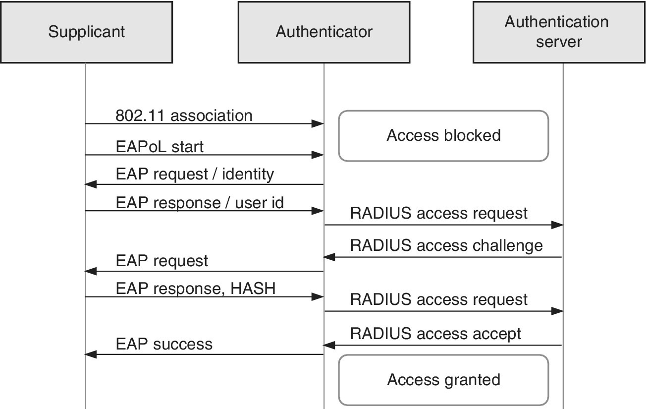
Figure 2.28 The flowchart of successful EAP authentication
The EAPoL protocol (EAP over LAN) is used on the radio interface between supplicant and authenticator. It includes the EAP protocol that is transferred over the RADIUS protocol. The authenticator divides the EAP part of the EAPoL, and sets it to communicate with the AS over the RADIUS. The Diameter protocol can also be used in this interface.
The RADIUS and Diameter protocols both support the EAP framework. It should be noted that the EAP is an authentication framework instead of an authentication mechanism. It provides common functions and negotiation of authentication procedures called EAP methods. The commonly applied modern methods that are capable of operating in wireless networks include EAP‐SIM, EAP‐AKA, EAP‐TLS, EAP‐TTLS and Extensible Authentication Protocol‐Lightweight Extensible Authentication Protocol (EAP‐LEAP). More specific requirements for the EAP methods applied in the WLAN authentication are described in Ref. [44].
The IEEE 802.1X introduces also the key exchange for the data encryption. As stated previously, the WEP encryption has been noted to be very weak. Based on the IEEE 802.1X feature which is designed to deliver dynamically the encryption keys, it is possible to use the enhanced security of WPA and WPA2.
The modern Wi‐Fi networks in the MNO environment typically support the IEEE 802.1X. It provides enhanced security, provides the use of enhanced authentication methods as well as new discovery features in Wi‐Fi networks [7].
2.6.6.4 EAP‐SIM, EAP‐AKA and EAP‐AKA’
The increased traffic flows along with the success of smartphones have generated an increased need for the data offloading. It may well be that the most essential success factor of the public Wi‐Fi services – observed from the user’s point of view – is the transparency of the authentication and the method for joining the Wi‐Fi network. In the MNO environment, which is mostly based on smartphone utilization, the EAP‐SIM [46], EAP‐AKA [47] and EAP‐AKA’ [45] authentication methods have been noted to be highly practical and useful. These methods are based on the SIM or USIM for authentication of users. On the network side it uses the Mobile Network subscriber information that resides in the HLR or HSS. It relies on the same data that is used for the 2G/3G/4G network authentication but in an enhanced way.
The key benefit of the EAP‐SIM in the smartphone is that it includes the SIM card along with the utilization of the already existing user database (HLR/HSS). As a result, the MNO can re‐use the existing infrastructure to provide a transparent authentication to the Wi‐Fi network, and the end‐user does not need to set any separate username and password on the client side. Additionally, the Wi‐Fi charging can be based on the cellular data so that the user may be charged via a single bill for the data utilization.
The EAP‐SIM functions with the older SIM cards and is based on GSM authentication. The newer EAP‐AKA and EAP‐AKA’ require 3G USIM cards to function, and they rely on the 3G network AKA authentication in an enhanced way to authenticate the Wi‐Fi users. The EAP‐SIM authentication uses IMSI as a mobile identity, and the authentication in the newer ones is based on Temporary IMSI (TMSI) for increased security [7].
2.6.6.5 EAP‐TLS
The EAP‐Transport Layer Security (EAP‐TLS) is defined in Ref. [48]. It provides strong security and uses a certificate and password for the user authentication. It is supported natively in several operation systems, including Windows, Windows Mobile, Mac OS and iOS. Most EAP‐TLS implementations require a unique client certificate which has reduced the adoption of the EAP‐TLS in the wider markets. It is thus used typically in the enterprise environment for laptops. In the normal case, the certificate is delivered on a smartcard by inserting it into the laptop’s smartcard reader, or by installing the certificate onto the laptop prior to its delivery.
A typical use case is an enterprise Wi‐Fi network based on IEEE 802.1X and EAP‐TLS. Once the laptop is equipped with an individual certificate (either smartcard or pre‐inserted certificate), and it is connected to the office Wi‐Fi network, it is possible to authenticate it automatically towards the company’s authentication server. The password can be given separately, or alternatively, a single‐sign‐on feature of the operation system may be used. As a result, the user is authenticated, data of the air interface is encrypted and the user may access the Intranet via the single process which is beneficial for the employees and employers [7].
2.6.6.6 EAP‐TTLS
The EAP‐Tunneled Transport Layer Security (EAP‐TTLS) is an EAP protocol that extends the TLS as defined in Ref. [49]. The difference with the EAP‐TLS is that the EAP‐TTLS does not require individual client certificate in order to authenticate to the server. In the authentication process, the server is first authenticated to the client securely (and optionally, the client is also authenticated to the server). Then, the server can establish a secure tunnelled connection to authenticate a client. The credentials (username and password) are transferred to the authentication database on that secure tunnel. The tunnel provides protection against eavesdropping and Man in the Middle (MITM) attacks.
There are two versions of EAP‐TTLS which are the original EAP‐TTLS (EAP‐TTLS v0) as described in Ref. [49], and EAP‐TTLS v1. The EAP‐SIM, EAP‐AKA and EAP‐TTLS are all feasible and practical authentication methods for the Wi‐Fi service providers since they do not require unique certificate to the device whereas the EAP‐TLS provides a user‐friendly authentication method to the Wi‐Fi networks in the managed corporate environment [7].
2.7 Interoperability
This section presents key aspects of the interoperability of 3GPP and non‐3GPP networks, Wi‐Fi Offload, Simultaneous Voice and LTE (SVLTE), signalling during location updates and in typical roaming scenarios. This section also presents examples and identifies potential security issues during the interoperability procedures. In the beginning of LTE/LTE‐A deployments, other RATs were already offered by the operators. As the LTE/LTE‐A coverage area is typically evolving and by the first network launch the service area is probably less than the offered 2G and/or 3G services, thus the inter‐working with the LTE/LTE‐A and the operator’s own RATs is essential to assure the fluent continuum of both voice and data calls [7].
2.7.1 Simultaneous Support for LTE/SAE and 2G/3G
One important item to be considered by the operators is related to LTE/SAE interaction with the existing 2G and 3G networks. It depends on the network support as well as device capability. The support for 2G/3G is by default built into LTE/SAE devices so that they are able to switch to 2G/3G whenever LTE/SAE is not available. However, it is not very straightforward to build a device which needs to be connected to both LTE/SAE and 2G/3G networks at the same time. This would require two separate radios functioning simultaneously, both connected to the core network. Likely it also requires two SIM cards.
Having this kind of device would solve a number of issues related to problems of handover between LTE/SAE and 2G/3G. For example, voice‐related functionality such as CSFB or Single Radio Voice Call Continuity (SRVCC) would not be needed since the LTE/SAE device would always be connected to the 2G/3G network, meaning the native CS voice service of 2G/3G would be available without any need for the handover. Nevertheless, due to the respective complexity of the phone design, e.g., size, cost, battery consumption and inter‐system interference caused by two simultaneously used radios, it is unlikely to that such devices will be deployed at the least in the initial phase of the networks.
The 3GPP specifications define the states of the LTE‐UE and state transitions, including inter‐RAT procedures. The states have been divided into an RRC_CONNECTED state (when an RRC connection has been established) and an RRC_IDLE state (when no RRC connection is established). The RRC states of the LTE‐UE are characterized according to the following.
2.7.1.1 RRC Idle State
The RRC Idle state means that the LTE‐UE controls the mobility and takes care of the monitoring of the paging channel in order to act when there is an incoming call waiting. In this state, the LTE‐UE takes care of the monitoring of the system information exchanging. Furthermore, for the LTE terminal models that support the Earthquake and Tsunami Warning System (ETWS), the terminal monitors the respective notifications that can be delivered via the paging channel. In addition to the paging channel monitoring, the LTE‐UE performs neighbouring cell measurements, cell selection and cell re‐selection procedures, and in general, is able to acquire system information from the LTE/SAE network.
2.7.1.2 RRC Connected State
The LTE‐UE is capable of delivering unicast data in downlink and uplink in the RRC Connected state. The mobility is controlled by the LTE/SAE network, meaning that the network takes care of the handover and cell change procedures order, possibly with additional support of network (NACC, Network Assisted Call Control) to 2G radio access network (GERAN). In this state, the LTE‐UE still monitors the paging channel and/or System Information Block Type 1 contents in order to detect system information changes. As in the Idle state, the LTE‐UE also monitors the ETWS notifications if the terminal is capable of supporting the system. Furthermore, the LTE‐UE monitors control channels that are associated with the shared data channel to determine if data is scheduled for it.
2.7.1.3 Mobility Support
The mobility of the LTE‐UE between LTE and 2G is illustrated in Figure 2.29, and the same idea is presented for 3G and CDMA2000 in Figure 2.30 and Figure 2.31, respectively. In the latter case, HRPD refers to High Rate Packet Data.
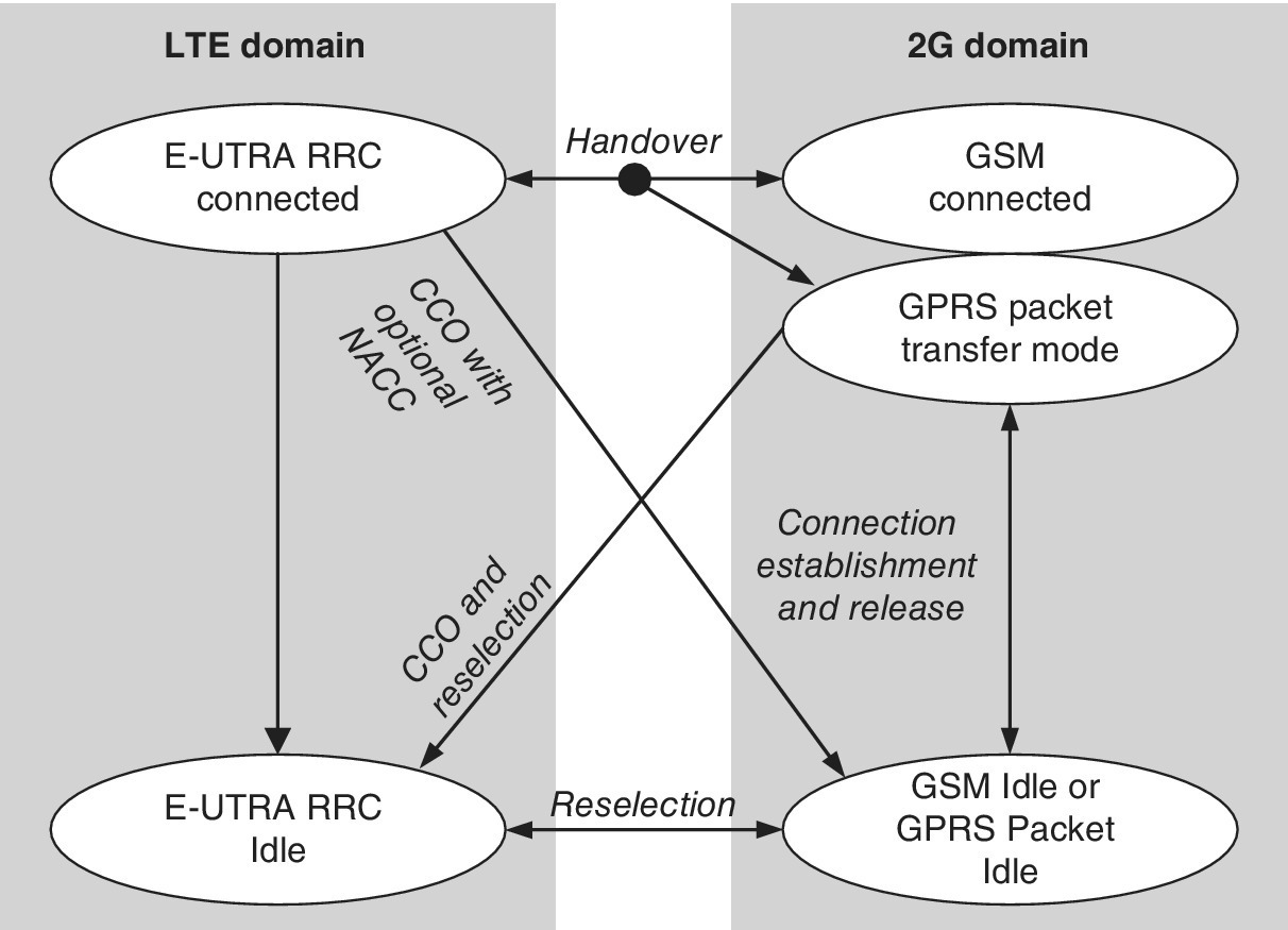
Figure 2.29 The LTE‐UE states and the inter‐RAT mobility procedures with the GSM network as interpreted from Ref. [38].
Source: Reprinted from [38] by courtesy of ETSI
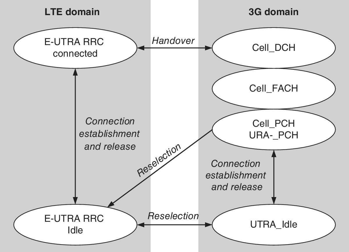
Figure 2.30 The LTE‐UE states and the inter‐RAT mobility procedures with the UMTS network as interpreted from Ref. [38].
Source: Reprinted from [38] by courtesy of ETSI
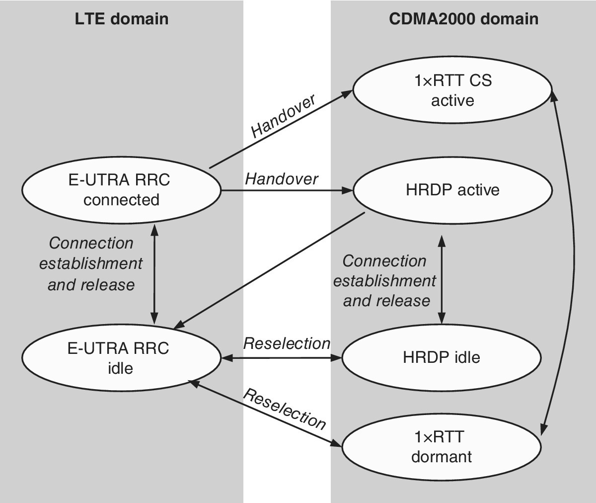
Figure 2.31 Mobility procedures between E‐UTRA and CDMA2000 as interpreted from Ref. [38].
Source: Reprinted from [38] by courtesy of ETSI
2.7.2 VoLTE
The network development typically follows the device evolution. The first LTE/LTE‐A networks were used merely as a big bit‐pipe providing customers with better bandwidth via data dongles. In the more advanced phase, the LTE/LTE‐A operators need to deploy additional core network elements and upgrade the CS core to offer functions such as CSFB, VoLTE and SRVCC. As indicated by GSMA and Next Generation Mobile Networks (NGMNs), the CSFB is considered to be the common interim solution for the voice service in LTE/SAE networks.
Since the VoLTE is a long‐term target, it will not be widely available in a commercial environment. This is because the IMS‐based IP voice deployment requires major work to be implemented due to the complexities of the IMS core system, related application servers, SRVCC support, QoS support in LTE/SAE RAN and Policy and Charging Control (PCC) architecture that are all likely to be required for a realistic CS voice replacement service. A related issue is the support for the CSFB and/or VoLTE for the inbound roamers.
2.7.3 CS Fallback
Even though the LTE/SAE is an all‐IP network, it also contains interfaces to the legacy networks. One example of this is the CSFB for voice service as defined in Ref. [62]. The CSFB means that the 2G/3G CS network is used to deliver the voice call for an LTE/SAE user. In the LTE/SAE, the delivery of the voice traffic would require some IP‐based solution like VoLTE or Over the Top (OTT). If these other mechanisms are not (yet) deployed, the feasible way to deliver voice traffic in LTE/SAE is via the existing 2G/3G network and the CSFB. 3GPP has also defined ‘Short Message Service (SMS) fallback’, which refers to SMS over the SGs interface, and allows the LTE/SAE device to send and receive short messages via the MME. Figure 2.32 depicts the procedure.
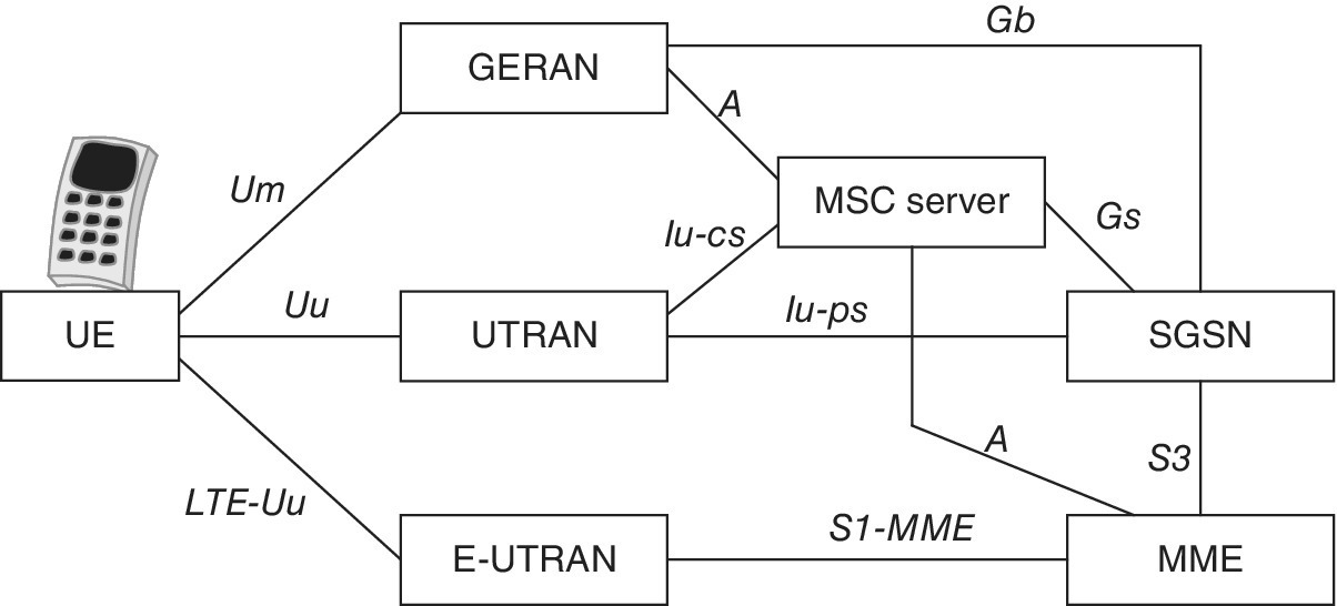
Figure 2.32 Enhanced Packet System (EPS) architecture for CSFB and SMS over SGs interface
Also the operator community of GSM Association and the NGMN are interpreting the CS Fallback as the common intermediate step towards the target solution of VoLTE, so therefore it likely is a part of many vendors’ roadmap [63].
2.7.4 Inter‐operator Security Aspects
In the LTE/SAE environment, it is important to consider the inter‐operator aspects, namely roaming and interconnection. The GSMA document IR.77 describes the general guidelines for the GPRS Roaming Exchange/IP Exchange (GRX/IPX) network, which are also valid when deploying, for example, LTE/SAE roaming regardless of the used service/application.
The main issues relate to the fact that GRX/IPX is a completely separated network, and in fact, it is not visible or accessible from the Internet. This requires core network nodes that are able to access both GRX/IPX and the Internet. They need to support multi‐homing or be capable of having two completely separate interfaces: one for the Internet and the other for the GRX/IPX. The IP addressing used for these interfaces needs to be separate as one cannot reuse the same IP address in GRX/IPX that is already utilized in the Internet.
Also additional guidance is required especially if another network such as the Internet is used for accessing other operators. This particularly relates to the native level of security offered by the network; the GRX/IPX can be considered to be secure as it is only accessible to operators that are part of the trusted parties whereas the Internet is open to everybody. So the Internet connectivity requires additional security‐related functions such as Session Border Controller (SBC) in order to guard incoming access and the IPSec tunnel for securing the traffic. Being essential parts in the inter‐operable environment, the security solutions also need to be simple and manageable to provide efficient fault, mis‐usage and fraud discovery.
2.7.5 Wi‐Fi Networks and Offload
Most mobile devices that are cellular data‐capable also include integrated Wi‐Fi capability. The importance of Wi‐Fi hotspots is increasing especially in dense Internet usage locations like airports, hotels and city centres. The operators are thus facing a challenge in the converged Wi‐Fi and cellular networks for ensuring secure and seamless handovers between the systems in such a way that the user experience is as fluent as possible.
Wi‐Fi Offloading provides a solution to this challenge. As identified in Ref. [24], the standardization has focused on both tight and loose coupling between the mobile communications networks and the Wi‐Fi access, depending on the forum. One of the 3GPP approaches is the Enhanced Generic Access Network (EGAN) architecture, which is based on tight coupling via rerouting the cellular network signalling through Wi‐Fi access networks. This results in Wi‐Fi being one of the 3GPP radio access networks. Figure 2.33 depicts the Wi‐Fi Offloading architecture.
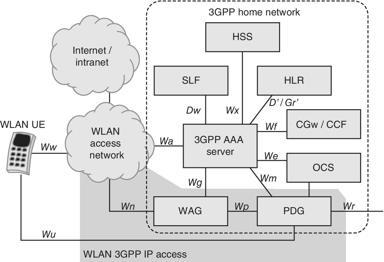
Figure 2.33 Wi‐Fi Offload architecture
There is also the loose coupling approach in 3GPP for Wi‐Fi via Interworking Wireless LAN (IWLAN) architecture. In this option, IP data can be delivered between mobile devices and the operator’s core network through a Wi‐Fi access. Here the mobile communications network and Wi‐Fi are handled in a separated way, and the client application decides the network selection. IWLAN architecture is based on the VPN or IPSec tunnel between the user device and dedicated IWLAN server that resides in the operator’s core network. Users can thus access the operator’s internal services or gateway that provides connection to Internet.
Only a few user equipments support native IPSec connectivity. Such user equipment requires an additional client. As Ref. [24] has noted, the impact of installing the extra client and its behaviour is a concern for new implementations. The simplest offload method for directing data to the Wi‐Fi network is via a public Internet connection relying on the non‐coupling option. In this case, there is no need for interworking standardization.
The Access Network Discovery and Selection Function (ANDSF) of 3GPP provides an advanced solution for the control of offloading between 3GPP and non‐3GPP access networks like Wi‐Fi hotspots. ANDSF has been designed to offer assistance for the discovery of access networks and to provide policies for prioritizing and managing connections.
The focus of ANDSF is to provide assistance to User Equipment (UE) in order to discover non‐3GPP access networks, e.g., Wi‐Fi and WiMAX that are suitable for data communications at the location in question in addition to 3GPP access networks. Furthermore, ANDSF is designed to provide the UE with rules policing the connection to these networks. Operators can list the preferred networks and provide automatically respective policies via ANDSF. ANDSF thus offers the possibility for carriers to enable Wi‐Fi hotspots with secure connectivity and seamless experience in locations where roaming between cellular and Wi‐Fi networks is controlled by operators. The combination of ANDSF and Hotspot 2.0 is an efficient enabler for enhanced and fluent user experience across Wi‐Fi and cellular networks. In order to maintain the adequate QoS level, Hotspot 2.0 provides a first‐step solution for roaming.
As identified in Ref. [24], there are three basic schemes for the initiation of the mobile offload to Wi‐Fi: WLAN scanning initiation (user device periodically performs WLAN scanning); user initiation (user selects the network technology); and remotely managed initiation (network server initiates the offloading).
2.7.6 Femtocell Architecture
The femtocell is a small mobile communications base station which has been designed primarily for the home or small business environment. The coverage area of a femtocell is limited to some tens of metres. It can be connected to the service provider’s network via broadband connectivity of, e.g., xDSL or cable. Figure 2.34 shows the femtocell architecture.
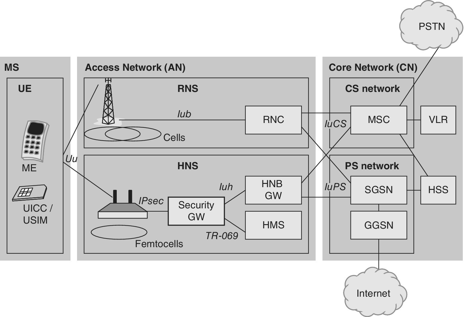
Figure 2.34 Femtocell architecture
At the moment, there is support for accessing typically 2–4 active mobile devices in the home environment and 8–16 active mobile devices in the business environment. The benefit of the femtocell is the extended radio coverage indoors assuring that possible outage areas can be covered. At a smaller scale, the enhanced coverage also has a positive impact on battery duration along with lower output power levels of user devices. Femtocells also provide capacity enhancement and enhanced QoS, e.g., for voice calls. The femtocell concept has been mainly designed for Wideband Code Division Multiplexing Access (WCDMA) but it is valid for other mobile communications standards like GSM, CDMA2000, TD‐SCDMA, WiMAX [37] and LTE. Furthermore, the concept allows the operator to design additional pricing strategies, e.g., customers may benefit from the utilization of the femtocell coverage areas.
In the femtocell deployment, it is worth noting that the concept works with existing handsets on the market as the equipment operates in the licensed spectrum. The Home NodeB (HNB) refers to the WCDMA femtocell of 3GPP systems, while HeNB refers to the femtocell deployed in LTE/LTE‐Advanced networks.
References
- [1] I. Androulidakis, D. Pylarinos and G. Kandus. Ciphering indicator approaches and user awareness. Maejo International Journal of Science and Technology, 6(3):514–527, 2012.
- [2] Aftenposten. The spoof GSM base stations revealed in Oslo, 16 December 2014. http://www.aftenposten.no/nyheter/iriks/Secret‐surveillance‐of‐Norways‐leaders‐detected‐7825278.html (accessed 4 July 2015).
- [3] 3GPP TSG SA WG3 Security – SA3#25 S3‐020557, 8–11 October 2002. http://www.3gpp.org/ftp/tsg_sa/wg3_security/tsgs3_25_munich/docs/pdf/S3‐020557.pdf (accessed 4 July 2015).
- [4] Wired . GSM spoof BTS demo, 31 July 2010. http://www.wired.com/2010/07/intercepting‐cell‐phone‐calls (accessed 4 July 2015).
- [5] Forbes . GPRS relay, 19 January 2011. http://www.forbes.com/sites/andygreenberg/2011/01/19/smartphone‐data‐vulnerable‐to‐base‐station‐spoof‐trick/ (accessed 4 July 2015).
- [6] Forbes . Information security of automotives, 8 April 2014. http://www.forbes.com/sites/andygreenberg/2014/04/08/darpa‐funded‐researchers‐help‐you‐learn‐to‐hack‐a‐car‐for‐a‐tenth‐the‐price (accessed 4 July 2015).
- [7] J. Penttinen. The Telecommunications Handbook. John Wiley & Sons, Inc., Hoboken, NJ, 2015.
- [8] Forbes . Security breach of vehicles. 8 April 2014. http://www.forbes.com/sites/andygreenberg/2014/04/08/darpa‐funded‐researchers‐help‐you‐learn‐to‐hack‐a‐car‐for‐a‐tenth‐the‐price/ (accessed 19 April 2015).
- [9] Verizon Security Breach Report, 2015. http://www.verizonenterprise.com/DBIR/2015/ (accessed 19 April 2015).
- [10] Wi‐Fi security description by Wi‐Fi Alliance, 2015. http://www.wi‐fi.org/discover‐wi‐fi/security (accessed 13 June 2015).
- [11] BBC. Mass snooping fake mobile towers 'uncovered in UK', 10 June 2015. http://www.bbc.com/news/business‐33076527 (accessed 14 June 2015).
- [12] 2016 Data Breach Investigation Report. Verizon, 2016.
- [13] Intel Curie, 2015. https://iq.intel.com/tiny‐brain‐wearables‐cute‐button/ (accessed 15 June 2015).
- [14] M. Green. A few thoughts on cryptographic engineering, 14 May 2013. http://blog.cryptographyengineering.com/2013/05/a‐few‐thoughts‐on‐cellular‐encryption.html (accessed 4 July 2015).
- [15] 3GPP TS 55.216 V6.2.0 (2003‐09). Technical Specification, 3rd Generation Partnership Project; Technical Specification Group Services and System Aspects; 3G Security; Specification of the A5/3 Encryption Algorithms for GSM and ECSD, and the GEA3 Encryption Algorithm for GPRS; Document 1: A5/3 and GEA3 Specifications. (Release 6).
- [16] J. Lei, Z. Han, M.A. Vazquez‐Castro and A. Hjørungnes. Secure satellite communication systems design with individual secrecy rate constraints, 2011.
- [17] M. Walker. On the security of 3GPP networks. Eurocrypt 2000.
- [18] Elad Barkan, Eli Biham and Nathan Keller. Instant ciphertext‐only cryptanalysis of GSM encrypted communication. Advances in Cryptology – CRYPTO 2003. Lecture Notes in Computer Science Volume 2729: 600–616, 2003.
- [19] ETSI TS 100 812‐2, V2.4.1. Terrestrial Trunked Radio (TETRA); Subscriber Identity Module to Mobile Equipment (TSIM‐ME) interface; Part 2: Universal Integrated Circuit Card (UICC); Characteristics of the TSIM application, 3 August 2005.
- [20] Jen Valentino‐Devries. Stingray phone tracker fuels constitutional clash. Wall Street Journal, 22 September 2011.
- [21] WPG Harris. Harris Wireless Products Group catalog, page 4. 25 August 2008. https://www.documentcloud.org/documents/1282631‐08‐08‐25‐2008‐harris‐wireless‐products‐group.html (accessed 4 August 2015).
- [22] L. Liang, S. Iyengar, H. Cruickshank and Z. Sun. Security for the flute over satellite networks. Proceedings, International Conference on Communications and Mobile Computing, Kunming, China, January 2009. Pp 485–491.
- [23] M. Mahmoud, N. Larrieu and A. Pirovano. An aeronautical data link security overview. Proceedings, IEEE/IAII Digital Avionics Systems Conference, Orlando, USA, October 2009. Pp 4.A.4‐1–4.A.4‐14.
- [24] 4G mobile broadband evolution. Release 10, Release 11 and beyond, HSPA+, SAE/LTE and LTE‐Advanced. 4G Americas. October 2012.
- [25] 3GPP TR 33.902. V3.1.0. January 2000. 3rd Generation Partnership Project; Technical Specification Group Services and System Aspects; 3G Security; Formal Analysis of the 3G Authentication Protocol (3G TR 33.902 version 3.1.0 Release 1999).
- [26] 3GPP TS 33.102. 3G security; Security architecture. V. 12.2.0, December 22, 2014.
- [27] C. Gabriel. Managing the new mobile data network. The challenge of deploying mobile broadband systems for profit. 2012. Rethink Technology Research.
- [28] Broadband technology overview. Corning, white paper, 2005.
- [29] Realistic LTE performance. From peak rate to subscriber experience. Motorola, white paper, 2009p.
- [30] J. Markendahl and Ö. Mäkitalo. Analysis of business opportunities of secondary use of spectrum. The case of TV white space for mobile broadband access. 22nd European Regional ITS Conference. Budapest, 18–21 September 2011.
- [31] P. Croy. LTE backhaul requirements. A reality check. Aviat Networks, white paper, 2011.
- [32] Realistic LTE performance. From peak rate to subscriber experience. Motorola, white paper, 2009.
- [33] New wireless broadband devices. Understanding the impact on networks. 4G Americas, May 2012p. http://www.4gamericas.org/UserFiles/file/White%20Papers/4G%20Americas%20White%20Paper%20New_Wireless_Broadband_Applications_and_Devices%20May%202012.pdf (accessed 28 February 2014).
- [34] Signaling considerations of apps. http://www.seven.com/mobile‐signaling‐storm.php (accessed 9 March 2014).
- [35] Traffic and market data report. Interim update. Ericsson, February 2012.
- [36] Launch of the 2014 Manual for Measuring ICT Access and Use by Households and Individuals. 11th World Telecommunication/ICT Indicators Symposium (WTIS‐13). ITU Document C/23‐E. Mexico City, México, 4–6 December 2013.
- [37] IEEE 802.16m technology introduction. White paper, Rohde&Schwarz, 2010.
- [38] 3GPP TS 36.331.
- [39] Limits of human exposure to radiofrequency electromagnetic fields in the frequency range from 3 kHz to 399 GHz. Safety Code 6. Environmental Health Directorate, Health Protection Branch. Publication 99‐EHD‐237. Minister of Public Works and Government Services, Canada, 1999.
- [40] J. Penttinen. The Telecommunications Handbook. John Wiley & Sons, Inc., Hoboken, NJ, 2015.
- [41] www.icnirp.de (accessed 14 September 2013).
- [42] J. Penttinen. The DVB‐H radio network planning and optimisation. Doctoral thesis, Aalto University, School of Electrical Engineering, 2011.
- [43] K. Zhao. Interaction between the radiation of LTE MIMO antennas in a mobile handset and the user’s body. Masters’ Degree Project, Kungliska Teknska Hogskolan, Stockholm, Sweden, June 2012.
- [44] IETF RFC 4017. Extensible Authentication Protocol (EAP) method requirements for wireless LANs. March 2005.
- [45] IETF RFC 4372. Chargeable user identity. January 2006.
- [46] IETF RFC 3579. RADIUS (Remote Authentication Dial In User Service) Support for Extensible Authentication Protocol (EAP). September 2003.
- [47] IETF RFC 3580. IEEE 802.1X Remote Authentication Dial In User Service (RADIUS) Usage Guidelines. September 2003.
- [48] IETF RFC 5216. The EAP‐TLS Authentication Protocol. March 2008.
- [49] IETF RFC 5281. Extensible Authentication Protocol Tunneled Transport Layer Security Authenticated Protocol Version 0 (EAP‐TTLSv0). August 2008.
- [50] Will Wi‐Fi relieve congestion on cellular networks? GSMA, 5 May 2014.
- [51] The Android SDK. http://developer.android.com/sdk/index.html (accessed 2 March 2014).
- [52] Android OS statistics. http://blogs.strategyanalytics.com/WSS/post/2014/07/30/Android‐Captured‐Record‐85‐Percent‐Share‐of‐Global‐Smartphone‐Shipments‐in‐Q2‐2014.aspx (accessed 16 November 2014).
- [53] The iOS SDK. https://developer.apple.com/devcenter/ios/index.action (accessed 2 March 2014).
- [54] The BlackBerry app development. http://developer.blackberry.com (accessed 8 June 2014).
- [55] The Windows Phone SDK. http://www.microsoft.com/en‐us/download/details.aspx?id=35471 (accessed 2 March 2014).
- [56] D. Tipper. IS‐95. Graduate Telecommunications and Networking Program, University of Pittsburgh. http://www.sis.pitt.edu/~dtipper/2720.html (accessed 31 December 2015).
- [57] D. Chen, M. Liu and X. Liu. Attacks and enhancement on security architecture of IS‐95. 14th International Conference on Communication Technology (ICCT). IEEE, Chengdu, China, 2012. Pp. 1143–1148.
- [58] F. Quick. Security in CDMA2000. ITU‐T workshop on Security, Seoul, Korea, 13–14 May, 2002.
- [59] L. Ertaul, S. Natte and G. Saldamli. Security evaluation of CDMA2000.
- [60] ITU statistics. Mobile phone penetration, 3 January 2016. http://www.itu.int/en/ITU‐D/Statistics/Pages/stat/default.aspx (accessed 3 January 2016).
- [61] IMEI Database of the GSMA, 3 January 2016. https://imeidb.gsma.com/imei/login.jsp (accessed 3 January 2016).
- [62] 3GPP TS 23.272.
- [63] CS Fallback. www.ngmn.org/news/ngmnnews/newssingle2/article/ngmn‐alliance‐delivers‐operatorss‐agreement‐to‐ensure‐roaming‐for‐voice‐over‐lte‐357.html (accessed 3 January 2016).
- [64] V. Niemi and K. Nyberg. UMTS Security. John Wiley & Sons, Ltd, Chichester, 2003.
- [65] D. Forsberg, G. Horn, W.‐D. Moeller and V. Niemi. LTE Security, 2nd Edition. John Wiley & Sons, Ltd, Chichester, 2012.
