
4
Smartcards and Secure Elements
4.1 Overview
This chapter presents key technologies related to smartcards and SEs, especially as they relate to the wireless systems. First, an introduction discusses why smartcards are still a useful and perhaps even indispensable anchor for security in the era of IoT. Nevertheless, the new environment may require updating of the systems and ways of utilization of the SEs. In fact, both the IoT – with its vast amount of M2M connected devices – and the consumer markets are starting to require physically much smaller SEs than we have typically seen to date in the form of traditional SIM cards. As a result of consumers’ small‐sized wearable devices and huge amounts of low‐cost M2M equipment all over the field, the principles for the subscription management may see a radical evolution from the traditional SIM OTA methods, which typically have been vendor‐specific.
The industry requires wider interoperability in order to ensure fluent and global mobility from which one example is the automotive environment; once the car has been built, it may end up in any country. So, if the respective car‐embedded communications system for cellular networks contains an initial subscription, it should be possible to change it to any operator’s system – not only for the initial activation but also for several changes during the lifetime of the communications equipment. These modifications need up‐to‐date international standards as well as new types of SIM cards that can be tiny, embedded elements to support IoT and consumer devices.
This chapter outlines the available and future alternatives for traditional and enhanced variants of smartcards. It also discusses the fact that SIM has no own Input/Output (I/O) capability and its impacts on the future solutions. Furthermore, it presents a technical description of contact cards with respective standards and current solutions, as well as contactless cards, form factors with current options and future extensions, and electrical and mechanical characteristics. This chapter also outlines the idea for the smartcard file structure and presents typical use cases of the cards as well as their future development.
4.2 Role of Smartcards and SEs
Smartcards represent a type of SE hardware. Examples of solutions for providing SEs are the SIM, UICC, eSE and external micro Secure Digital (SD) cards. Smartcards can be categorized by their physical characteristics such as contact and contactless variants, and by their functionality such as memory cards, Central Processing Unit (CPU) or Multi Processing Unit (MPU) cards with embedded OS, multi‐mode communications cards and hybrid cards. The cards may be used, e.g., as a transport access system’s wireless component and contact chip, dual‐interface cards and as multi‐component cards like an integrated fingerprint reader. The most relevant cards for the wireless systems are the contact cards in the form of SIM/UICC, which may also support the contactless communications via connectivity from the chip PINs to the device’s NFC chip and antenna. Furthermore, the M2M area has been the driver for the embedded SIM, which refers to the soldered SE with the same functionality as the removable SIM/UICC.
The smartcard concept is relatively old as such, having been invented in the 1970s, and commercial products introduced into the markets in the 1980s. In the early stage of the commercial phase, smartcards were utilized largely in prepaid telephony by applying a counter for the call credit utilization. Other examples of the early stage smartcards are vending machine and public transport payment cards, student ID cards (sometimes combined with the vending machine payment concept) and library cards.
The simple form of the smartcard is a memory card with embedded Electrically Erasable Read Only Memory (EEPROM) which is connected to address and security logics of the card, the latter having the input/output (I/O) signalling with the external world based on the clock signalling. The EEPROM of these cards typically has a very small storage size, low amount of write and erase events and about 10 ms delay in writing an individual cell or group of cells.
The microprocessor card is an advanced variant of smartcards as it includes a Central Processing Unit (CPU) which connects the card’s internal EEPROM, ROM and Random Access Memory (RAM). The CPU also connects the external world via I/O and clock ports. In this type of card, the EEPROM stores data while the ROM contains the card’s OS and the RAM module is meant for the working storage.
The early stage microprocessor cards had a small memory size for the EEPROM, RAM and ROM, and a slow and low‐bit CPU, the capacity and performance increasing along with the development of the IT technologies. As an example, the SIM card of mobile communications was based on an 8‐bit CPU and only a few kB of EEPROM in the early stage of GSM deployments, which was still sufficient to store small phonebook information. Nevertheless, as the SMS was deployed some years after the first‐phase GSM networks, the card’s internal memory no longer sufficed for storing the received messages until upgraded cards with a larger memory size were introduced to the market.
As the mobile communications system functionality is advancing with vast leaps, the current LTE MNOs typically require SIM size from 64 kB up to several hundreds of MB. There are SIM cards in the current markets exceeding 1 MB. Furthermore, the card’s chip is nowadays typically based on a flash memory type that optimizes the memory allocation for OS and other required functionality, instead of dedicating the OS in a separate ROM block.
Along with the further development of smartcards in the operational environment, to support more memory size, advanced functionality such as flash memory and modern technologies to speed up the processor speed, they continue to be a useful and even indispensable anchor for providing the security platform in current and future mobile communications such as in the era of IoT. They also provide useful additional functionality, e.g., storing more information and secure domains for multiple stakeholders per single smartcard.
It can be expected that the increasing number of IoT devices will result in considerably more active intentions for exploiting the vulnerabilities of the mobile services and networks. Thus, it can be assumed that further modifications will be needed for smartcards to support IoT such as remote management of the SE, which in mobile devices refers to either removable or embedded SIM/UICC. The basic concept of the smartcard as such is a functional and secure platform for supporting current and new telecommunications and other mobile services, and for the further development of solutions like dynamic subscription management when switching operators, almost in real time, to download, activate, switch and delete the subscriptions. The technical base, including advanced chip technologies and smaller form factors for the embedded (soldered) HW elements, ensure the usability of the concept far into the future to support current and new types of tiny devices such as consumer wearables and ultra‐small personal area network devices such as digested intestine monitoring equipment embedded within a medical capsule. The HW‐based security of the tamper‐resistant SIM/UICC can be assumed to guarantee better security and protection level compared to pure SW‐based solutions such as HCE although both can be further enhanced. Furthermore, there are no obstacles to combine the SW and HW‐based security solutions to jointly guarantee the highest security level combined with the flexibility of the cloud‐based solutions such as token‐based mobile payment.
The fact that SIM has no own I/O capability is both a limitation and a benefit as the direct manipulation of the contents is not possible, and the communication happens in a very controlled way via APDU messages and their acknowledgements. As an example, copying the stored keys or any other contents for their further observation is not directly possible in the way it is via the file manager of a typical computer OS.
Smartcards have been standardized internationally. The aim has been to ensure the interoperability at a general level although the final functionality depends on the adopted system. Some examples of highly interoperable environments are the NFC‐based contactless bank cards as well as the contact SIM/UICC cards of 3GPP systems.
Smartcards can be divided into sub‐categories to distinguish between contact cards, contactless cards and multi‐component cards. Furthermore, the cards can be memory cards, CPU/MPU cards under both contact and contactless card types (or combination of these in the dual‐interface card format) while the multi‐component cards can contain many current and innovative new card types such as vault cards, dynamic token display cards and biometrics authentication cards based on, e.g., fingerprints or eye iris data. For the wireless communications, the contact card in the form of SIM/UICC is the most typical although along with the growing IoT/M2M devices as well as consumer devices such as wearables, the form factor of embedded UICC options is shrinking.
The major categories for the SEs are the UICC, eUICC and microSD. The UICC is the base for the ‘traditional’ MNO business model. Its base is still relevant even if its precedent variant, the first SIM cards, were deployed in GSM networks in 1991. The evolution path of the SIM/UICC include, e.g., Host Controller Interface (HCI), Single Wire Protocol (SWP) and NFC.
The eUICC is a feasible base for M2M environments, and increasingly also for the consumer markets along with the increasing importance of the wearables [6]. Nevertheless, the only internationally standardized eUICC is the MFF2 which might be somewhat voluminous for the smallest IoT equipment. The rest of the currently available variants are based on the chipset vendors’ proprietary specifications (especially the size and PIN layout, as well as other electromechanical characteristics) unless the standardization community activates for defining the smaller eUICC. The benefit of the eUICC is that the SE is directly soldered into the device, but if the initial subscription is changed in the interoperable environment, it requires further standardization for the subscription management. The current options are discussed further in this book.
Finally, the microSD is an SE platform that is provided by a thirdparty, and it is independent from the MNOs. If such a removable element is supported by the device (as is the case typically in current smart device markets), it may be used for secure services such as mobile wallet and transport access.
The above‐mentioned variants can be utilized in the complete ecosystem in various technical environments [19]. As some examples, the NFC‐based payment solutions may rely on respective service providers, app developers, credit card issuers, MNOs, NFC‐compliant merchants and TSM concept. That role division model typically includes certification schemes by the service provider, which need to be complied by the card vendors, OEMs and MNOs. The model has two sub‐categories, basing on either a removable NFC‐enabled UICC (with, e.g. an already obsolete SoftCard payment app) or an embedded NFC chip (with, e.g., a Google payment app). The certification model may be time‐consuming. For that reason, the model has been challenging in some cases, as the SoftCard initiative showed, resulting in ramping down the consortium and respective mobile payment service while other mobile payment schemes appear on the market.
In addition to the payment environment, the UICCs and other forms of SEs can be utilized in the access and transit environments, basically replacing the physical keys with SW‐based access. The access use case may contain roles for the access company via TSM and venue (like hotel) corporations. This model makes it unnecessary to rely on physical door keys or access cards as the same functionality can be provided via mobile devices with UICC or eUICC and a respective access app. The app can further provide physical access rights for many other locations such as home and office, depending on the included (and to be added further) rights.
Variations of this model can be used in the transit environment to replace the pass by including CA, TSM and payment provider. The involved app may contain passes in several transport systems such as subway, train, bus and ferry in a local and wider geographical areas as long as the apps support the systems.
4.3 Contact Cards
The physical and logical requirements of contact cards like SIM/UICC cards have been standardized and recommended in various standardization bodies and industry forums. The globally agreed principles ensure the interoperability of the cards and their applications, reader and mobile devices, networks, card issuers systems and services. The ISO/IEC 7816 standard set is the base for contact cards used in mobile communications [4,5]. The standard defines the physical card size, Form Factors (FFs), pin contact layout, electrical characteristics, I/O protocols that can be byte or block based and file structure.
Recently, there are more use cases valid in the mobile communications markets along with the M2M connectivity and dynamic management of subscriptions both in M2M and consumer environments. Thus, the interoperability needs to be extended to cover the events in subscription management like remote downloading of the subscription, and the activation, deactivation, changing and deletion of it.
The standardization organizations and industry forums relevant to wireless communications security are presented in Chapter 1 while the most important principles of the smartcard standards and recommendations are discussed in the following sections. They summarize the ISO/IEC 7816 sub‐standards for the integrated cards.
4.3.1 ISO/IEC 7816‐1
The latest version of this standard is ISO/IEC 7816‐1:2011, which specifies the physical characteristics of ICCs with contacts of the ID‐1 card type. It may include embossing, magnetic stripe and tactile identifier mark as specified in ISO/IEC 7811. The respective test methods are specified in ISO/IEC 10373‐1. The standard applies to cards with a physical interface and electrical contacts.
The standard contains the requirements for the physical characteristics of ICCs, including exposure limits for X‐rays, UV light, electromagnetic fields, static electrical fields and ambient temperature of the card. It also presents physical requirements for bending in order to ensure the functionality for the planned lifetime in a practical environment as the embedded chips need to maintain firmly their position in the plastic frame, and guarantee a certain stress level on the exposed connectors and the internal pins of the embedded silicon die.
The material of the card body is typically made of Acrylonitrile Butadiene Styrene (ABS) or Polyethylene Terepthalate (PET) which are both more than adequate for environmental compatibility compared to Polyvinyl Chloride (PVC). Nevertheless, the body can also be made of other materials such as compostable materials like cornstarch, hemp fibres, bamboo and cellulose. The treatment of these materials is not straightforward as they need to be treated in a special manner to meet international standards and norms, which is the reason for the popularity of the easier handled and environmentally compatible ABS, PET, Polyethylene Terepthalate Glygol (PETG) and Polycarbonate (PC), especially as the printing material (ink) is also ecologically acceptable.
The critical part of the SIM card is the plug‐in module which contains the electrical chip module and metallic contact points. It needs to be physically strong enough when placed into the card reader tray of the device. Nevertheless, the rest of the card body may be of another type of material which complies even more with the environmental aspects. Also, the size of the traditionally utilized full card body (ID‐1) can be reduced, from which one example is the half‐SIM body (ID‐1/2). Yet another solution is to provide a plug‐in‐only SIM card, which is not attached to the actual card body at all, the typically printed related information being in a separate leaflet.
In the commercial market, the material of the SIM card delivery can further be optimized by providing the accompanying packet with less material or more environmental compatible substances. Also, the environmental aspects can be enhanced by optimizing the SIM lifecycle so instead of changing the physical card during the lifetime, it is possible to update subscription‐related information OTA methodologies which are described later in this book. Logically the recycling can also be optimized upon the end‐of‐lifecycle by recycling the utilized material, the respective providers ensuring the subscriber data is securely and confidentially deleted when the card is returned.
4.3.2 ISO/IEC 7816‐2
The ISO/IEC 7816‐2 standard dictates the number, function, dimensions and position of the contact areas of the electrical parts. The full‐size ICC consists of eight electrical contact points which are named as C1…C8, not all of which are necessarily used by the respective embedded microprocessor chip. Table 4.1 summarizes the contact definitions of ISO 7816‐2.
Table 4.1 The ISO/IEC 7816‐2 ICC contacts
| Contact | Use | Description |
| C1 | Vcc | Operating voltage for the microprocessor. Originally, the supply voltage was 5 V, and the support for 3 and 1.8 V was added later. Nowadays, the support of 5 V is merely optional |
| C2 | RST | Reset signal for microprocessor to initiate the reset sequence |
| C3 | CLK | Clock for the card’s microprocessor originated from the device. The clock rate dictates the operation speed and functions as a base for the communications to and from the microprocessor and external world |
| C4 | RFU | Originally marked as ‘reserved for future use’. Can be used for connectivity‐oriented USB 2.0 interface (1/2) via 8‐contact modules |
| C5 | GND | Common ground |
| C6 | Vpp | Programming voltage for the 1G ICC’s EEPROM. In the later phase, used for NFC contact via standardized SWP/HCI |
| C7 | I/O | Input/output, half‐duplex serial data channel for reader and smartcard. This provides physical channel for exchanging APDU messages |
| C8 | RFU | Originally marked as ‘reserved for future use’. Can be used for connectivity‐oriented USB 2.0 interface (2/2) via 8‐contact modules |
For the internal use of the card itself, the optional functionalities are Vpp, Vcc and CLK. The RST is utilized either as itself provided by the external device, or optionally as a combination with the card. Nevertheless, if internal reset is used, the Vcc is mandatory, which refers to the power supply input. Contacts C4 and C8 are defined separately in respective standards. The SIM/UICC card originally consisted of a full set of eight PIN connections. PIN 6, which supports SWP, forms an interface between the Contactless Frontend (CLF) and SIM/UICC. In practice, it is a contact‐based, bit‐oriented, full duplex protocol for contactless communication (like NFC) in such a way that the CLF is the master and the SIM/UICC is the slave. The CLF supplies the UICC with operating power, clock reference, data (via binary‐state voltage and current levels of the single wire) and bus management signalling.
Along with the size reduction of the SIM/UICC cards, a variant for a 6‐PIN layout was also introduced. Figure 4.1 shows the original and later pin layout for the 8‐PIN variant, as well as the latest 6‐PIN layout while Figure 4.2 summarizes the functions of the PINs.
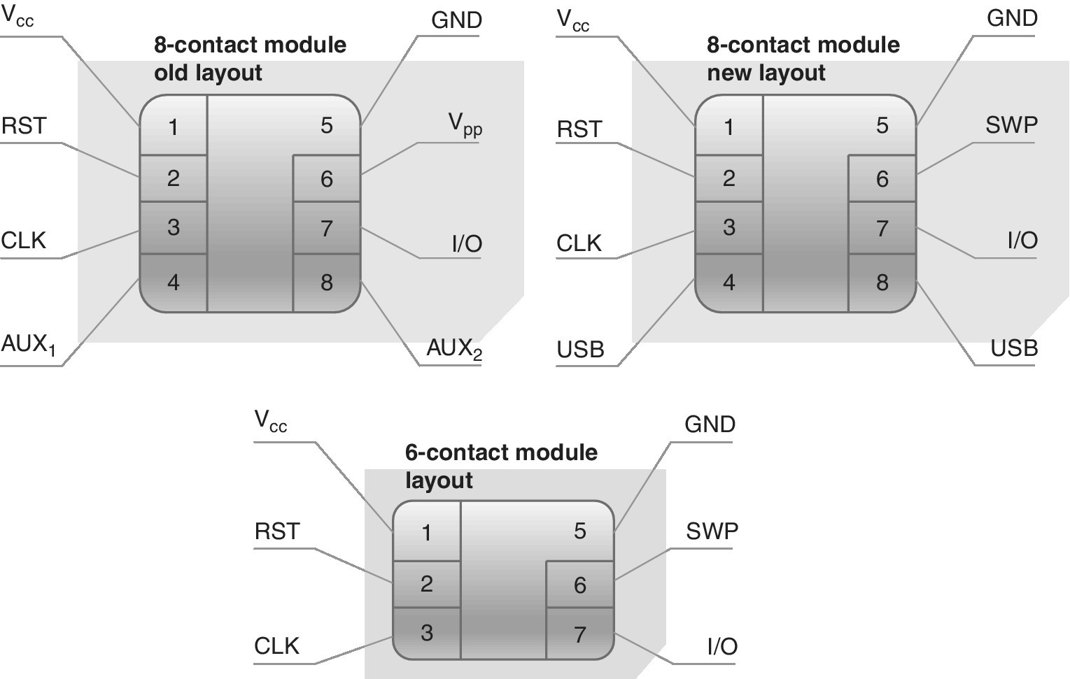
Figure 4.1 The physical connections of the UICC
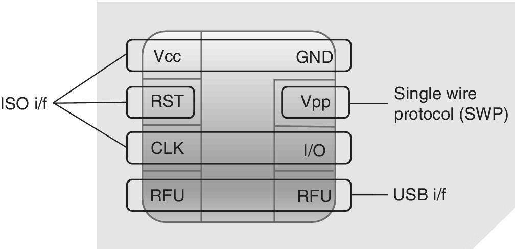
Figure 4.2 Physical interfaces of the 8‐PIN UICC based on ISO, SWP and USB
4.3.3 ISO/IEC 7816‐3
ISO 7816‐3 is relevant for establishing communication with a smartcard and for writing I/O software from, e.g., microcontroller, serial and parallel ports as well as via the USB port. The basic idea of these communications is to send a signal to the card which returns an Answer to Reset (ATR). ISO 7816‐3 contains definitions for the respective electrical signals, voltage and current values, operating procedure for ICCs, ATR in both synchronous and asynchronous modes, and Protocol Type Selection (PTS). The protocol type T = 0 represents the original asynchronous half duplex character‐based transmission protocol, while the T = 1 protocol is a half‐duplex asynchronous block‐based transmission protocol. As Ref. [23] states, the terminal must support both T = 0 and T = 1 protocols, while the UICC may support either T = 0 or T = 1, or both.
4.3.4 ISO/IEC 7816‐4
ISO/IEC 7816‐4 defines the message contents, commands and responses between the connected interface device and the card itself. It also contains definitions for the structure and content of the bytes produced by the card for ATR, the file and data structure that is observed in the interface upon processing inter‐industry commands for interchange, file and data access methods, secure messaging, and access to the algorithms processed by the card. It should be noted that ISO/IEC 7816‐4 does not describe the respective algorithms.
4.3.5 ISO/IEC 7816‐5
This sub‐standard describes the registration of application providers. It defines the use of an application identifier to ascertain the presence of and perform the retrieval of an application in a card. The standard thus explains the procedure for granting unique application identifiers via the international registration. It also defines the respective authorities, the register related to the identifiers and the application providers.
4.3.6 ISO/IEC 7816‐6
This sub‐standard describes inter‐industry data elements for interchange, and specifies the Data Elements (DEs) for inter‐industry interchange of ICCs. The standard is valid for both contact cards and contactless cards. The standard describes the identifier, name, description, format, coding and layout of DEs, and defines the ways for retrieval of DEs from the card.
4.3.7 ISO/IEC 7816‐7
This sub‐standard describes inter‐industry commands for the Structured Card Query Language (SCQL). As noted in Ref. [36], the commands for access are based on SQL functionality as defined in ISO 9075, and coded according to the principles of inter‐industry commands as defined in ISO/IEC 7816‐4. The database is a structured set of database objects referred to as Database File (DBF). Under a selected Dedicated File (DF), there cannot be more than one DBF which is accessible after selection of the respective DF. A database may also be directly attached to the Master File (MF). One typical example of the multi‐application card is that under the MF, there may be several DFs. Under the selected DF, there can be a DBF at the same structural level with other internal elementary files and/or working elementary files. The respective DF and its contents underneath is referred to as an application with a database.
4.3.8 ISO/IEC 7816‐8
This sub‐standard defines inter‐industry commands for security operations for contact and contactless ICCs which are used for cryptographic operations. The commands of this sub‐standard are based on the ones defined by ISO/IEC 7816‐4, with added new commands. The operations may be related to digital signatures, certificates and the management of asymmetric keys.
4.3.9 ISO/IEC 7816‐9
This sub‐standard defines industry commands for card and file management during its complete lifecycle. Typical use cases of these procedures include file creation and deletion, secure downloading of data into the card (including applets, keys and other code) and secure messaging.
4.3.10 ISO/IEC 7816‐10
This sub‐standard defines electronic signals and ATR signals for synchronous cards and terminals. The standard includes definitions for the power and signal structures.
4.3.11 ISO/IEC 7816‐11
This sub‐standard defines personal verification through biometric methods by describing the inter‐industry commands and data objects that can be used for user verification. The actual commands are found in the ISO/IEC 7816‐4 standard, and parts of the commands are found in ISO/IEC 19785‐1. ISO/IEC 7816‐11 also discusses the enrolment and verification, and emphasizes security issues.
4.3.12 ISO/IEC 7816‐12
This sub‐standard defines the USB electrical interface and operating procedures for cards with contacts (USB‐ICC). The standard includes definitions for USB‐ICC as an interface device, standard and class descriptors, bulk transfers and control transfers between USB‐ICC and terminal, control transfers for version A and B protocols, interrupt transfers to indicate asynchronous events, and status and error conditions. The two protocols for control transfers are the protocol T = 0 (version A) or the transfer on APDU level (version B).
4.3.13 ISO/IEC 7816‐13
This sub‐standard defines commands for application management in a multi‐application environment.
4.3.14 ISO/IEC 7816‐15
This sub‐standard is related to cryptographic information application, specifying a card application and a common syntax in the Abstract Syntax Notation One (ASN.1) format for the cryptographic information and sharing mechanisms. The standard also includes the card’s storage of multiple instances of cryptographic information, use and retrieval of the cryptographic information, authentication mechanisms and cryptographic algorithms.
4.4 The SIM/UICC
4.4.1 Terminology
As for the terminology of this book, the SIM refers primarily to the HW of the original SIM of GSM. The original ETSI‐based SIM is designed to work with 2G GSM mobile communications system devices, including further enhancements like GPRS, Enhanced Data Rates for Global Evolution (EDGE) and other GSM‐specific solutions.
Nevertheless, the SIM has been upgraded for 3GPP systems at the 3G stage and beyond, including UMTS/HSPA, LTE and LTE‐A. Along with the development of the 3GPP mobile communications systems beyond 2G, the original SIM HW has also been enhanced and is called the UICC in the 3GPP 3G systems. The UICC can support several radio access technologies as well as other wireless solutions, each being handled by a separate application on the UICC. The 2G and 3G telecommunications systems are managed via an application called USIM. In order to distinguish between 2G and 3G systems residing on the UICC, the application specifically supporting the GSM is called ‘USIM with 2G context’, or simply ‘GSM’, while the application supporting 3G (UMTS/HSPA) is called ‘USIM with 3G context’, or simply ‘USIM’. Furthermore, the application supporting LTE as of 3GPP Release 8 refers to the LTE‐specific files specified in the 3GPP TS 31.102. In all these 2G and 3G phases, the module is called USIM, but the LTE‐specific functionality for the IMS voice calls is managed via a separate ISIM (IMS SIM) application.
In general, the original 2G SIM is compatible with later 3GPP generations, but is only able to provide services limited to 2G. Furthermore, in order to provide backwards compatibility, the 3G USIM can be utilized in 2G devices although the 3G‐specific functionalities are not available in such setups if the device does not support them.
Not only 3GPP systems but also American CDMA networks (1xRT, EVDO, HRPD and eHRPD) can be supported by the UICC. The respective application is called Removable User Identity Module (RUIM) or CDMA SIM (CSIM) [38]. In this book, the terms SIM and USIM are used separately when emphasizing the 2G and 3G differences, respectively, and otherwise the general term UICC, or combined form SIM/UICC, are used for referring to the mobile communications subscription of all the 3GPP systems.
The physical aspects of the UICC are based on the ISO 7816 standard for contact cards. Furthermore, the ETSI TR 102 216 defines the UICC as a smartcard that conforms to the specifications written and maintained by the ETSI Smartcard Platform project. There is also the contactless standard ISO 14443 which is used as a basis for NFC.
4.4.2 Principle
The UICC is a security element which acts as a part of the complete security chain of the 3GPP mobile communications networks and in other supporting networks. It is a tamper‐resistant HW‐containing file and folder system for various security environments, complying with the Common Criteria Evaluation Assurance Level (CC EAL) 4. It can be considered sufficiently well protected for storing secure applets, which are applications that require high levels of security including the protection of application assets in confidentiality, integrity or availability at different security levels depending on the AP’s security policy. Such a high level of security assurance is typically required for payment applications complying with CC EAL 4 with AVA_VAN.5 or with higher EAL class, Conditional Access (CA) mobile TV applications or digital signature applications. As an example, a Protection Profile, Secure Signature‐Creation Device (PP SSCD) is required in Europe for qualified digital signature applications [7]. The PP defines the security requirements of an SSCD for the generation of Signature‐Creation Data (SCD) and the creation of qualified electronic signatures. In this specific case, the assurance level for the PP is EAL 4‐augmented [37]. More details about SSCD, including its lifecycle in development and operational phases, can be found in Ref. [37] Secure Applications (SAs) follow a CC evaluation and certification along with the certified (U)SIM [8].
The SIM/UICC is associated with its unique serial number (ICCID), IMSI as well as authentication and ciphering information. There are other related information fields such as TMSI associated by the network, a list of services the subscriber is entitled to and PIN1/PIN2 codes (primary and secondary) as well as a PUK code.
The SIM/UICC can be used as a base for offering services to the end‐users via Java applets. Along with the development of content providing, there are increasing needs for securing the communications. Thus MNOs may want to further develop new value‐added services based on UICC platforms for areas like mobile payment, electronic signature, mobile TV and mobile identity, which may require increased security levels of the traditional SIM/UICC, depending on the service provider’s needs [9]. An example of a solution for such environments is TEE which is discussed more detailed later in this book. Higher level authorities may also be interested in ensuring sufficient protection for secure mobile services, e.g., the French Network and Information Security Agency has created certification reports that indicate the features of the proposed security targets, including the compliance for the EAL 4 or higher [10].
4.4.3 Key Standards
The SIM card was standardized by ETSI inTS 11.11, which defines the physical and logical functions of the card. Along with the transition of GSM and UMTS standardization work from ETSI to 3GPP, the SIM‐related standardization was moved partially to 3GPP. As a result, 3GPP takes care of the further development of applications like GSM SIM (TS 51.011) and 3G USIM (TS 31.102) while ETSI continues developing the physical UICC.
While the 3GPP works basically on the USIM‐related topics, some of the key ETSI standards for the UICC are the following:
- ETSI TS 102 221, physical and logical characteristics of UICC–terminal interface.
- ETSI TS 102 412, smartcard platform requirements, stage 1.
- ETSI TS 102 613. UICC–CLF) interface, part 1, for physical and data link layer characteristics.
- ETSI TS 102 600, characteristics of the USB interface in UICC–terminal interface.
- ETSI TS 102 484, secure channel between a UICC and an end‐point terminal.
- ETSI TS 102 223, Card Application Toolkit (CAT).
- ETSI TS 131 102, application‐specific details for applications residing on an ICC (USIM for 3G).
An important security‐related topic for the UICC security is the compliance with the CC. It refers to standards denoting EALs from 1 through 7 as summarized in Chapter 1.
Especially for the SIM Application Toolkit (SAT), the initial specification of ETSI was TS 11.14. Nowadays, the enhanced SAT is defined jointly by ETSI and 3GPP, the key standards being ETSI TS 102 223, ETSI TS 102 241, ETSI TS 102 588 and ETSI TS 131 111. The SAT applications were originally based on proprietary APIs, but along with the introduction of the Java Card, it is possible to provide better interoperability of the applications.
4.4.4 Form Factors
The SIM card was introduced in mobile communications systems along with the first GSM deployments as of 1991. It is based on the contact card definitions of ISO/IEC 7816. The first SIM card with Form Factor 1 (1FF), as presented in Figure 4.3, was designed based on the size of a standard credit card to provide a convenient way for storing and fluent transportability of subscription data between all GSM devices. The main idea of this complete separation of the user equipment and user account is still applied in GSM and advanced 3GPP systems.
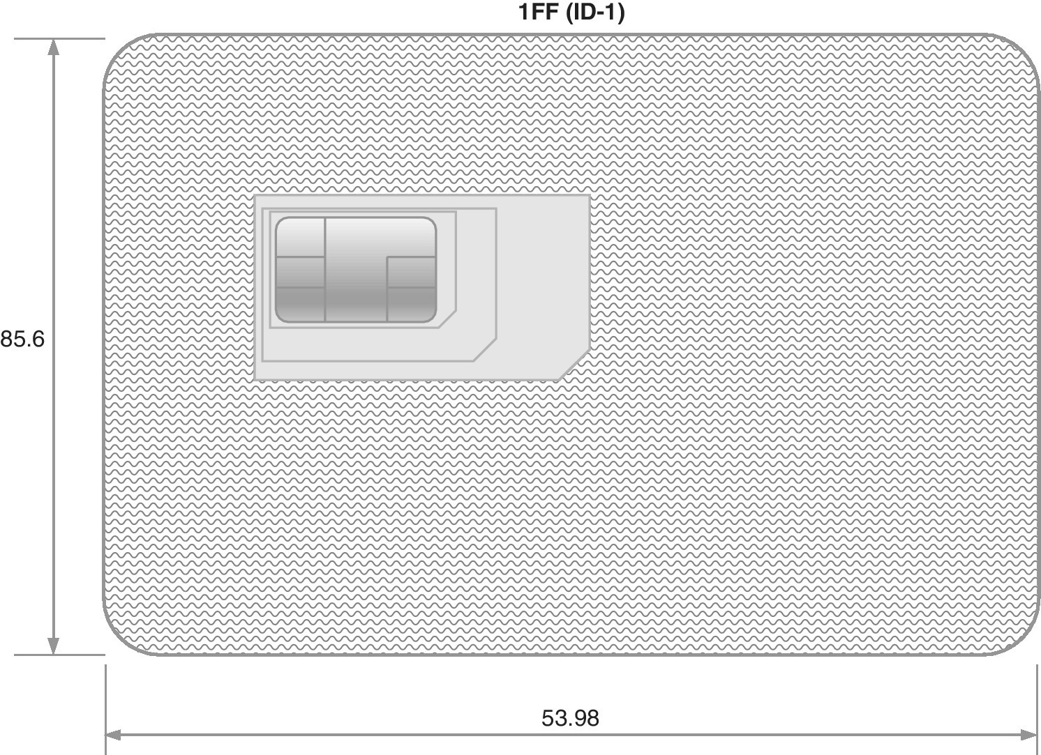
Figure 4.3 The 1FF of SIM cards (dimensions in mm), which is also called ID‐1. The thickness is 0.76 mm. The ID‐1 is used in practice only for delivering the plug‐in units which are further snapped out from the card body when inserting them to mobile devices
The initiation of the GSM SIM card era happened in 1991 when the smartcard provider Giesecke & Devrient provided the world’s first subscription modules to a Finnish MNO, Radiolinja [2]. Soon after the first form factor (which is the same size as the ID‐1 card body), the reduction of the GSM hand‐held device’s size resulted in the second SIM Form Factor (2FF), i.e., a mini card which is roughly a stamp‐sized smartcard.
The SIM card’s plug‐in part has further been resized as a result of the need for reduction of the physical size of the mobile devices. The third Form Factor (3FF), i.e., a micro card, was introduced in 2010 in the commercial markets. It was specified by ETSI in cooperation with the ETSI Project Smartcard Platform (EP SCP), 3GPP (for UTRAN/GERAN), 3GPP2 (for CDMA2000), ARIB, GSM Association (by GSMA SCaG and GSMNA), GlobalPlatform, Liberty Alliance and the OMA for optimizing the space for devices that benefit from reduced space. To date, the smallest consumer SIM with fourth Form Factor (4FF), or nano card, entered the commercial markets in 2012. Both 3FF and 4FF are backwards compatible with previous variants, so the contact area has been retained (for the active 6‐PIN layout). In addition, the processing is executed with the same 5 MHz rate. The nano SIM is, though, slightly thinner than previous variants. Table 4.2 and Figure 4.4 summarize the key aspects of consumer SIM cards.
Table 4.2 Consumer‐grade SIM FF
| Form Factor | Name | Standard | Length (mm) | Width (mm) | Thickness (mm) |
| 1FF | Full‐size | ISO/IEC 7810:2003, ID‐1 | 85.60 | 53.98 | 0.76 |
| 2FF | Mini/plugin | ISO/IEC 7810:2003, ID‐1/000 | 25.0 | 15.0 | 0.76 |
| 3FF | Micro | ETSI TS 102 221, V.9.0.0 | 15.0 | 12.0 | 0.76 |
| 4FF | Nano | ETSI TS 102 221, V.11.0.0 | 12.3 | 8.8 | 0.67 |
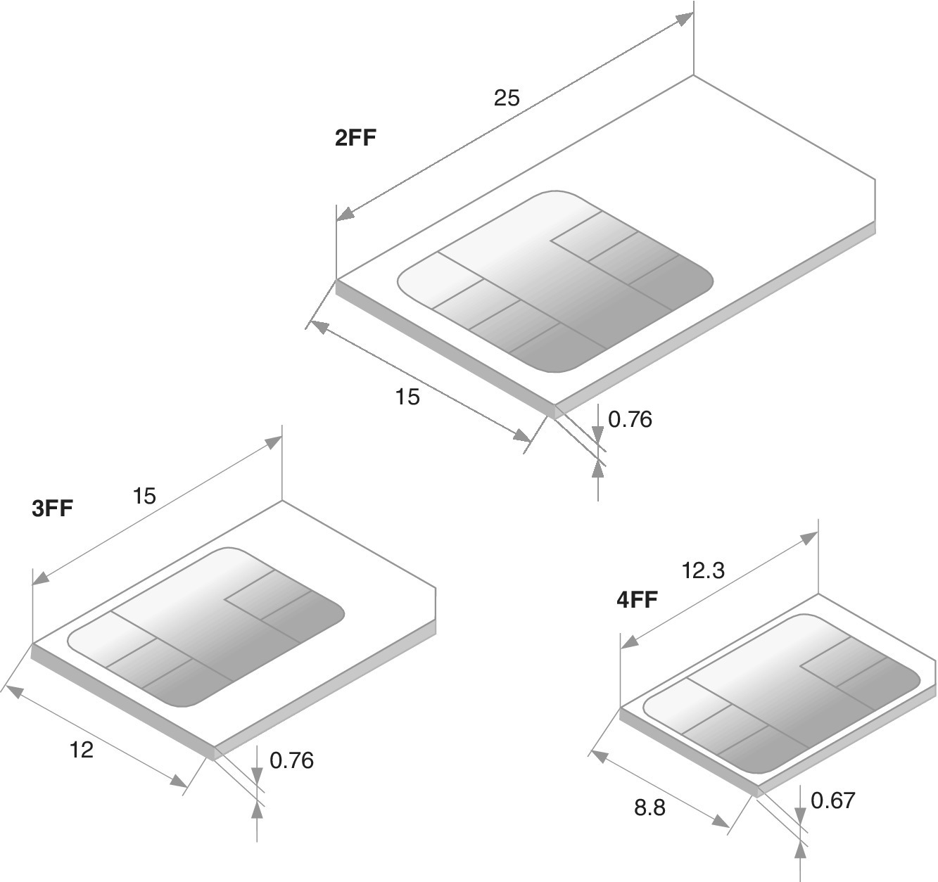
Figure 4.4 SIM card’s 2FF, 3FF and 4FF plug‐in units (dimensions in mm)
Typically, the plug‐in unit, whether it is 2FF, 3FF, 4FF or combination of these, is attached to the ID‐1 card frame. More specifically, the smaller card consists of the same PIN contact arrangement as for the full‐size 1FF SIM card and is typically supplied within a full‐size card carrier which supports the plug‐in part via connecting pieces. This method is described in the ISO/IEC 7810 specification which defines the ID‐1/000, and it provides a means for using the card either with a device (card reader) designed for a full‐size card, or by physically detaching the plug‐in part and inserting it to a device supporting that form factor. In addition to the form factor size definitions, the chip PIN contacts can have different shapes. The visual aspect is not only decorative but it dictates how the embedding of the card is done onto the frame. Ref. [12] describes the interface between the UICC and terminal (card reader), and Ref. [11] defines further the M2M UICC physical and logical characteristics. Figure 4.6 depicts the mechanical components of the smartcard.
The SIM plug‐in modules have been typically delivered by operators attached individually in ID‐1 frames. The challenge of this method is the increased diversity of user equipment and the variations in the supported SIM form factors. Typically, the devices only accept either plug‐in SIM (2FF), micro‐SIM (3FF), or nano‐SIM (4FF) cards. This leads to the challenges of physical stock maintenance for offering this variable set of SIM. Typically, it is not clear for end‐users which form factor each user equipment requires.
One solution to tackle the limited support of different SIM/UICC form factors is a physical adapter that is either 2FF or 3FF in size, and that can accommodate a smaller plug‐in unit to guarantee compatibility for the SIM insertion. Another way is to cut the plug‐in unit into smaller 3FF or 4FF sizes as the actual electronics is within the surface of the visible metallic contacts. There are specially designed cutting tools available for this type of size adjustment, but it should be noted that such an operation may void the warranties of the card itself as well as the device the modified card is utilized with.
This situation has led to offering more sophisticated solutions like triple‐SIM as presented in Figure 4.5[1]. As can be interpreted from Figure 4.4, the nano‐SIM is thinner than any other SIM variant. The triple‐SIM solution takes this into account as the nano‐SIM part is thinner at its rear side compared to the rest of the card surface. For MNOs, the benefits of the double‐ and triple‐SIM solutions include logistical savings as a single card body for all the relevant form factors provides simpler inventory management. Also the Order Management (OM) process can be simplified at the point of sale, and there can be assumed to be less customer care calls as end‐users do not need to solve the physical dimension incompatibility issues for inserting the SIM card into the device. This results in reduced customer care calls, and the overall end‐user experience is enhanced. The end‐users can also benefit from the fact that the new devices typically support smaller form factors; the changing of the old SIM card can thus be done by resizing the already obtained card to a smaller form factor.
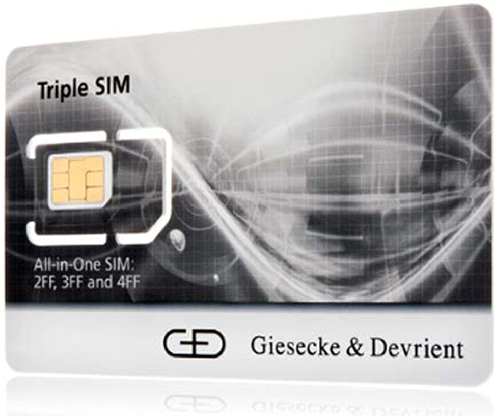
Figure 4.5 The plug‐in units of 2FF or 3FF can be delivered within a single ID‐1 card body. This eases the logistics and enhances user experience upon inserting the plug‐in units into mobile devices.
Photo reprinted by courtesy of Giesecke & Devrient
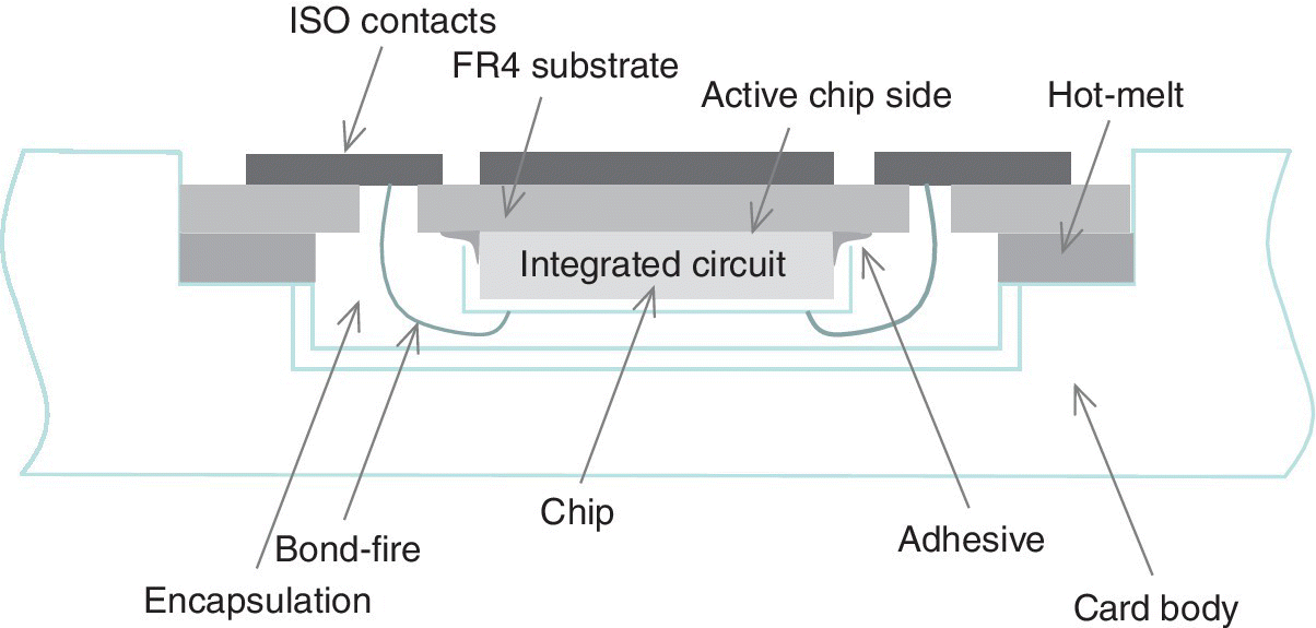
Figure 4.6 The physical building blocks of a smartcard. The ID‐1 card body can be of plastics or recyclable materials, while the frame material of the plug‐in needs to comply with typically stricter mechanical and environmental requirements making plastics the most feasible material
4.5 Contents of the SIM
4.5.1 UICC Building Blocks
4.5.1.1 Types of UICC Subscription Containers
The SIM was introduced into the markets along with the deployment of the GSM. The original SIM was designed to work in the ETSI/3GPP 2G environment. The physical SIM card is based on the ISO 7816 definitions which detail the UICC contact cards. Furthermore, the wireless variant based on NFC is defined in ISO 14443.
The USIM was introduced along with the 3G mobile system of ETSI/3GPP. USIM is backwards compatible with the ETSI/3GPP 2G system, although when the user is connected to the GSM network, the advanced properties of the USIM cannot be applied.
The RUIM is a smartcard variant designed for the CDMA networks, and standardized by 3GPP2. As is the case for 3GPP SIM and USIM of GSM and UMTS, the RUIM stores the user’s subscription data including identity, phonebook addresses, feature‐specific information, network settings and supplementary services for CDMA handsets. Typically, CDMA handsets include this data in‐built to the device’s HW (which means that CDMA handsets are personalized), but with the RUIM, the MNOs are able to implement smartcards and provide the advantage of subscription‐related data portability as has been the case with GSM and UMTS. Furthermore, the RUIM provides the same SAT principle as has been offered via the SIM and USIM as a basis for value added services, as well as OTA management of data. When utilized within a multi‐application card, other applications can also be stored in addition to the RUIM, like SIM and USIM, which provides roaming capabilities for the handsets supporting the respective parallel technologies. Please note that the CDMA‐specific smartcard is also called CSIM (CDMA‐SIM).
The ISIM is a recent addition to the previous set of applications. The ISIM is meant for the Voice over LTE. The ISIM thus refers to the application residing on UICC that provides access to the IMS.
The TSIM refers to the SIM in the TETRA system as defined in Ref. [39].
In general terms, the SIM, USIM, ISIM, TSIM and RUIM (CSIM) are referred to as Subscription Containers of the UICC. The UICCs are used for security procedures, data storage and applications. As part of the security, the UICC holds authentication and encryption keys for accessing networks and for securing OTA transactions. The data storage contains a set of information like service configuration parameters, phonebook, short messages, as well as service and emergency numbers. The card may also contain diverse services like Location Based Services (LBSs) and information services.
The concept of the card applications has developed vastly since the initial introduction of the SIM. The first phase of the development was based on proprietary applications which were fast to finalize but, at the same time, they lacked interoperability and they were challenging to maintain. At that time, the role of the SIM was to act in the lowest layer while the SAT managed the applications in the upper layer. Some examples of the early SAT applications were banking and location services. In a parallel fashion, there was also the Wireless Identity Module (WIM) residing on the UICC that took care of the WAP browsing services.
Later development of the open system application environment that is based on Java programming ensures better interoperability. This has had a positive impact on the time to market of applications. Furthermore, the application development no longer depends on the respective card manufacturer, thanks to the standardized API definitions as presented in the Java standards and 3GPP TS 03.19.
4.5.1.2 Profile
The card profile refers to the contents of the UICC, i.e., to the specification of the file system as well as to the general and individual data which is personalized onto the SIM, USIM and other subscription containers. In other words, the profile contains the UICC file system. The profile can be visualized by a tree structure that presents the nodes as files and applications residing within the UICC. The root node is the profile itself. Under the root node, there is a set of information which indicates the card characteristics, the UICC file system including the master file, the UICC files and applications. The complete (U)SIM framework consists thus of the initialized module and profile, and the profile contains file system, applications and switches for the functionality.
The most relevant UICC profile‐related specifications are the following. The 3GPP TS 31.102 lists Elementary Files (EFs) in the profile while the 3GPP TS 23.097 describes the multi‐user profile. The 3GPP TS 22.097 describes the Multiple Subscriber Profile (MSP) service which allows the served subscriber to have several profiles, and to distinguish between telecommunications service requirements, e.g., for business and home. The subscriber data specific to the MSP is stored in the HLR and GSM Service Control Function (gsmSCF). The 3GPP TS 23.008 defines the data stored in the HLR. The HLR element contains all the common data, i.e., the data valid for all profiles, and some data specific to the default profile. The 3GPP TS 31.101 defines the four EFs that reside in the MF level. The EFs at the USIM Application Dedicated File (ADF) level contain service and network related information as defined in 3GPP TS 3.102.
For creating the (U)SIM profile, there are special SW personalization tools capable of producing system‐related files (MF and EFs) and the actual personalization. The MF is created at the time that the telecommunications subsystem is installed. It should be noted that there also is a Configuration Elementary File (EFConf) which transparently stores the card configuration parameters. It is mandatory for the card functioning and must therefore not be deleted.
The minimum file system on the (U)SIM card must contain the following files: the MF which is created at the installation of the telecommunications sub‐system, EF CONF, EF GSM_PIN_CFG, EF DIR, EF USIM_PIN_GBL, EF USIM_PIN_PUK, EF ARR, ADF USIM and EF USIM_PIN_LOC. In the data generation phase, these files must be created in the given order. The applications of the card (applets, or native applications) can be installed directly via the card commands by using the ISO interface or via OTA, e.g., by a RAM application.
4.5.1.3 SIM HW Blocks
The main HW blocks of the SIM card are CPU, RAM, ROM and EEPROM. The CPU may function in cooperation with the assisting Numerical Processing Unit (NPU). The RAM is meant for the operating memory while the ROM is meant for permanently stored contents like the OS. The EEPROM is a non‐volatile memory block used for changing data such as a phonebook.
4.5.1.4 OS
Each SIM/UICC has an embedded card OS which manages the communications between the card and external world as well as takes care of the functions of the card such as cryptographic procedures. The card OS is SIM/UICC vendor‐ specific and it provides practical ways to differentiate between competing card providers. Nevertheless, the abstraction of the functions via Java Card provides a means to use interoperable Java applications at least to some extent.
4.5.2 The SIM Application Toolkit (SAT)
The SIM Application Toolkit (SAT) refers to a solution that enables the SIM to perform actions related to value‐added services. The SAT typically initiates upon the powering up the SIM, and it provides a means to interact with the applications of the SIM. It is standardized by ETSI and 3GPP, and was originally designed for GSM in ETSI GSM 11.14 technical specification. Nowadays, there is also an SAT for the 3G USIM as defined in 3GPP 31.111 Release 4, named USIM Application Toolkit, or USAT.
The SAT/USAT contains commands within the SIM/UICC that can be executed apart from the respective mobile device or the mobile network. One of the use cases of the SAT/USAT is to display menus and collect user input by the SIM/UICC commands, thus facilitating interactivity between the SIM/UICC, network applications, access networks and the subscriber.
The key benefit of the SAT/USAT is the possibility to create a simple user interface that shows options of the commands to the end‐user. Although by default not ‘fancy‐looking’, this menu structure allows the utilization of respective services with various types of mobile devices including the basic and feature phones as well as the most complete smartphones and connected devices. The SAT/USAT is thus most useful in a low‐level application environment.
Along with the initial Java Card concept, the platforms for SAT services started to emerge at the beginning of 2000. Ever since, the Java Card and SAT have been developed further as new 3GPP releases have been published while the interoperability aspects of the SAT and Java Cards are taken care of by the SIM Alliance. It can be estimated that the development will continue as new developments enter the mobile communications market. Some examples of these are services related to the Smartcard Web Server (SCWS) and NFC, which may interact with the (U)SIM in an advanced way. Since the early days of the SIM card, it has evolved from being merely a user authentication solution to a comprehensive services platform for operators, and provides a means for the execution of applications such as phonebook synchronization or SAT menus which enhance the discovery and usage of operator services.
As one step further in the SIM development, the SCWS represents a new generation of SIM application environments. The SCWS functions as a base for developing, executing and distributing content‐rich applications from the (U)SIM, now based on web technologies. The SCWS provides an upgraded user interface which enhances the earlier, monographic SAT menus with more appealing visual aspects for the card applications. Furthermore, it is based on the HTTP 1.1 web server embedded in the (U)SIM which facilitates the development and distribution of SIM/UICC applications. The SCWS is thus an application residing in the smartcard which implements an HTTP 1.1 server defined by the IETF in RFC 2616. Thirdly, the SCWS enhances the connectivity with remote web servers which makes client/server applications adaptive to the evolution in network data rates [20].
The benefit of the SCWS is that any application developed using the SCWS technology can be used by the end‐users using the SIM, independently of the device type. The SCWS provides communication with HTTP clients such as the handset browser, which at the same time works as a user interface for services and applications. Also, an administration server can manage SCWS‐based applications and their content remotely, thus facilitating OTA SIM/UICC card customization, e.g., for updated applications and content.
The SCWS implements in a tamper‐proof device security between the relevant nodes of its ecosystem. The solution includes security of data at the transport level with OMA standards based on PSK TLS and the implementation of GlobalPlatform standards benefiting the application‐level security, which is relevant especially for operators and banks.
In practice, the SCWS content of the smartcard can be accessed via a URL, e.g., via an Internet browser which gives access to static resources like xHTML files, images, multimedia files and other formats managed by the HTTP client (browser). The URL can also be handled by a web application within the card so that the installed SCWS web applications may provide dynamic content. The application is triggered as soon as the Internet browser requests a URL mapped to a web application, resulting in the dynamic generation of the xHTML page.
The SCWS includes mechanisms to secure the HTTP connection in order to protect the environment. This can happen via HTTP‐based user authentication mechanisms, or via the authentication and confidentiality by implementing HTTP over TLS (i.e., HTTPs). It is also possible to control access to the SCWS from device applications by OMA‐defined Access Control Policy (ACP). As a result of these OMA mechanisms, the card is seen as a client, and the OTA platform acts as a server whereas the communication is based on web protocols (HTTPS) so that the security layer is represented by TLS in a pre‐shared key mode.
The SCWS works with the classic ISO cards which communicate via Bearer Independent Protocol (BIP) TCP server mode with the handset, and the USB‐IC cards which support high speed communication protocols and that communicate with the handset supporting either BIP TCP server mode or TCP/IP mode. The SCWS thus uses BIP over the ISO 7816 interface or TCP/IP stack over the USB UICC‐Terminal interface [20].
4.5.3 Contents of the UICC
The UICC is a platform for a multitude of applications. It is specified by 3GPP TC SCP, and it consists of application‐independent functions and features so that there is a clear separation between lower layers and applications. There is also a set of up to 20 logical channels for accessing the applications in a parallel manner as shown in Figure 4.7. The ‘SIM’ and ‘USIM’ are thus some of the many applications within the UICC, these ones providing telecommunications services whereas other applications may be related to, e.g., mobile payment.
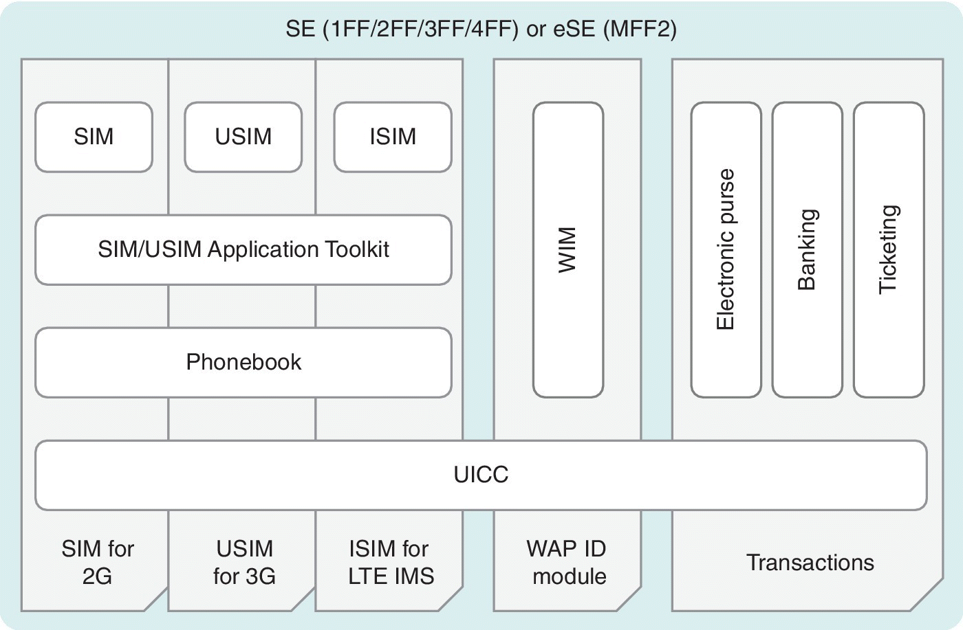
Figure 4.7 An example of the system level building blocks of a multi‐application card based on the UICC. The applications may also include other subscription containers like RUIM for CDMA systems, and applets for many areas such as transit access and payments
4.6 Embedded SEs
4.6.1 Principle
The basic principle of the UICC is the transportability of the subscription data between the user’s devices so that there is no need to update the HW of the device. Thus, the subscriber’s mobile telephone number, among other data like phonebook, is possible to maintain with the new device by inserting the UICC card into it.
For the M2M environment, special conditions have emerged compared to the consumer UICC cards. The physical and logical characteristics of the M2M UICC cards are specified by ETSI Technical Committee Smartcard Platform (TC SCP) [11]. It includes, e.g., definitions of environmental classes which indicate the temperature ranges and other conditions under which the UICC is designed to work.
The evolution of the M2M environment has brought along the eUICC which is not physically accessible or replaceable by the user. Changing the subscription on such devices is challenging if using ‘traditional’ ways, which has resulted in the need for new methods to securely and remotely provision the access credentials on the eUICCs, and furthermore, to manage the subscriptions if they are swapped between MNOs.
4.6.2 M2M Subscription Management
The ETSI specification TS 103 383 defines the requirements for the eUICC subscription management [34]. Release 13, published in October 2015, describes the remote management of the eUICC for the purposes of changing an MNO subscription without requiring physical removal and replacement of the UICC. It also presents several use cases such as provisioning of multiple eUICCs for M2M devices like utility meters, security cameras and telematics devices, provisioning of the eUICC for the first subscription with a newly connected device, and changing thesubscription for a device. Figure 4.8 depicts the logical aspects of the eUICC architecture and associated security credentials as interpreted from Ref. [34].
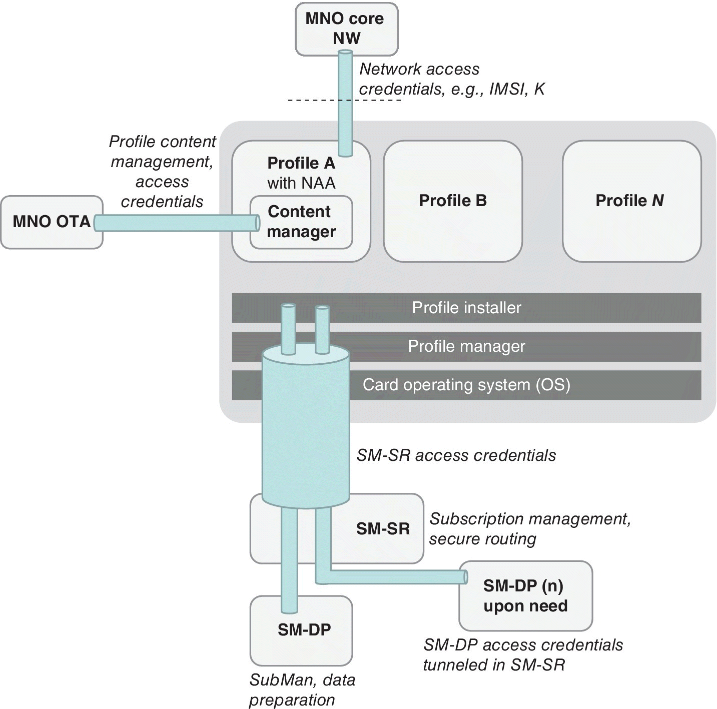
Figure 4.8 The eUICC logical architecture as interpreted from ETSI TS 103 383
ETSI has documented use cases for the eUICC, e.g., for the M2M provisioning, end‐user provisioning and network redundancy. Figure 4.9 presents potential use cases in this area.
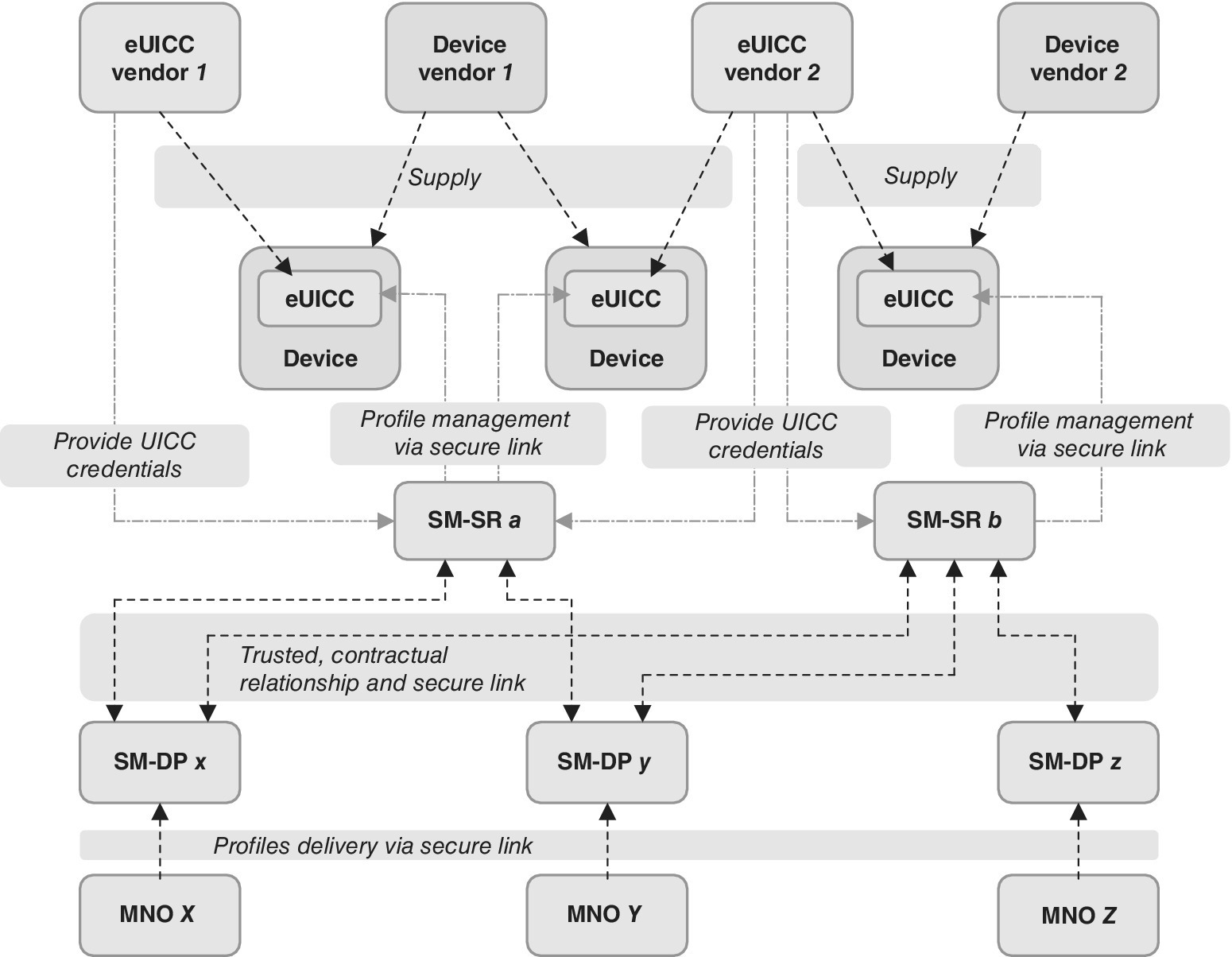
Figure 4.9 Some ETSI eUICC use cases for redundant subscription management
The role of OEM, MNO and end‐user for the eUICC activation has been under active discussion in ETSI, as well as in various other standardization and industry associations like SIMalliance, GSMA and GlobalPlatform during 2015. The current consensus indicates that the development of interoperable, international subscription management is highly important for both M2M and consumer environments which requires additional efforts to come to a final conclusion between the different standardizing entities.
As an example of the GSMA justifications of subscription management development, some common key statements for the benefits of the enhanced subscription management solution include accelerating the market growth of M2M and increasing operational efficiency for the M2M ecosystem, as well as enabling remote or OTA installation and management for operator profiles. Furthermore, the new solutions cut operational and physical logistics costs as there is no need to ship physically UICCs or change physical UICCs for an entire product lifetime. It also enables new business models, prevents market fragmentation by avoiding different, incompatible technical solutions, and drives economies of scale within the M2M industry. The GSMA embedded SIM has been developed to promote a common global remote provisioning architecture for the new era of M2M technology and to accelerate the M2M market [34]. The business environment of device types will thus change during the forthcoming years. According to the estimations of GSMA, the role of the mobile handset connections will soon lower from the 92% level in 2015 to 80%, while the role of M2M connected devices will grow considerably.
GSMA has identified various benefits for the eUICC. For many M2M applications, the use of traditional SIM cards is problematic because M2M modems are often inaccessible, making it difficult to insert or change SIM cards once the modem is deployed in the field. The use of the eUICC enabling remote operator profile provisioning overcomes these restrictions. The eUICC simplifies logistical processes as the UICC capability can be installed into the M2M modem at the point of manufacturing which can later be remotely provisioned with the operator profile. The eUICC removes the need for stock control and shipping of physical, pre‐provisioned UICC cards. This operational flexibility is delivered with no compromise on security. Figure 4.10 presents the GSMA view to the eUICC architecture [33].
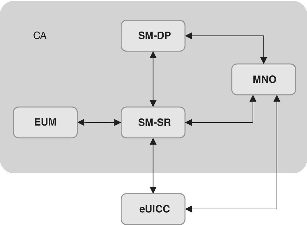
Figure 4.10 The embedded UICC architecture of GSMA as interpreted from Ref. [33]
As can be seen from Figure 4.10, the subscription management changes the traditional linear embedded UICC lifecycle model which personalizes the UICC for a known MNO until the end of life of the UICC into the new model that is based on basic personalization. In the new model, after the distribution, the UICC can be personalized with the operational profile for a given MNO until the end of subscription, and the UICC can be changed for a new MNO by re‐personalizing the card.
In the GSMA model, the Subscription Manager, Data Preparation (SM‐DP) securely packages profiles that are ready to be provisioned on the eUICC, and installs the profiles onto the eUICC. The Subscription Manager, Secure Routing (SM‐SR) securely transports the eUICC profile management commands for loading, enabling, disabling and deletion of the profiles in eUICC. The role of eUICC manufacturer (EUM) is to provide the needed SM‐SR functionality whereas the MNO infrastructure physically transfers the data onto the eUICC. The Certificate Authority (CA) is involved to ensure the trust chain in the information exchange.
The M2M and other connected IoT devices benefit the most from eUICC technology. Nevertheless, the importance of consumer applications can be expected to grow, the benefit being the enhanced user experience compared to the current switching and swapping processes.
In addition to the ETSI Ref. [34] about the topic, further information about the GSMA solution can be found in Ref. [33], which details the latest available technical description of the GSMA’s remote provisioning architecture version 2.1 for the eUICC published in November 2015. Other entities currently driving for interoperable, international standards for the subscription management include SIMalliance and GlobalPlatform.
4.6.3 Personalization
The personalization of the SIM/UICC refers to the process of creating the file system of the card and loading the corresponding data such as USIM and other applications into the smartcard according to the profile. This data is placed into the memory of the chip which is typically flash memory. The customer profiles that are planned for a commercial environment are typically tested thoroughly by utilizing a set of laboratory and operational test cards among the stakeholders such as card vendors and operators. The profile configuration and format are vendor, operator and product dependent. Once tested by the stakeholders and validated by the operator, the commercial cards are produced via order management, which is an operator‐dependent process. It may be based on automatized electrical or manual formats which detail the requested card parameters, including the graphical layout, form factor and delivery address and expected date.
4.6.4 M2M SIM Types
In practice, there are different M2M UICC types that each vendor provides, including the form factors utilized in consumer space and embedded UICCs. The industry and automotive grade UICCs are typically made to be more robust and durable compared to the consumer products to support long‐term utilization. The aimed functional lifetime of the industry and automotive UICCs may be typically 10–17 years. The vendor‐specific requirements are stricter for these variants due to harsher environmental conditions and use cases. As an example, it can be estimated that the UICCs in the automotive environment need to function for a number of years in a wide range of climate conditions.
The M2M UICC can take advantage of all the form factors. Typically, ruggedized 2FF as well as embedded MFF2 have been utilized in the M2M environment including the automotive industry. Along with the introduction of smaller equipment in the current and forthcoming IoT waves, the need for smaller SIM elements is obvious as well as the need for more dynamic management of the subscription data. The respective advances in subscription management is discussed in further chapters while the following paragraphs clarify the physical aspects of the embedded SEs utilized in M2M and consumer environments. The embedded UICC has been meant principally for M2M applications, but along with the introduction of small user devices such as wearables, it is increasingly useful for the consumer segment.
The surface‐mounted eUICC does not differ as such from the removable UICC (e.g., 2FF, 3FF and 4FF) as all these variants provide the same electrical interface. The main differentiator is the size and volume, and the fact that it is soldered on the circuit board during the manufacturing process while the removable variants can be freely exchanged between mobile devices.
It could be argued that especially in the M2M environment, once the IoT device has been taken into use, there is barely any need to change the subscription information. This has been the case traditionally, but the high dynamics of the M2M communications is indicating a need for managing the subscription data, including changing the network operator or service provider, even more than once during the lifetime of the eUICC. An example of such an environment could be the automotive industry; once the initial subscription has been installed at the car manufacturing premises, the car could end up in different countries and under a different network operator’s subscription. Furthermore, there might be a need to provide roaming and active communications, including changing the subscription, once the car is moved to another country. As the eUICC would not be replaced physically, this requires more advanced subscription management to guarantee updated subscription data downloading, switching, activation and deleting.
As for the electrical connections durability of the HW element, it can be assumed that in the M2M environment, which does not require changing the physical card/element, it is easier to ensure less wearing of the connector, which in turn improves the reliability of the functioning of the embedded element or permanently installed (and ruggedized) card.
At the moment, the Machine‐to‐Machine Form Factor 2 (MFF2) is the only internationally standardized embedded UICC form factor. It can also be called as a general term of the Machine Identity Module (MIM). Its form factor is referred to as DFN‐8, SON‐8 or VQFN‐8, depending on the vendor environment. As for ETSI terminology, it is called MFF2, as it has been defined in the ETSI M2M UICC standard TS 102.671. The physical aspects of the MFF2 are standard in JEDEC Design Guide 4.8, and its size is 6.0 × 5.0 × less than 1.0 mm. There are other alternatives in the non‐standard markets (complying vendor‐dependent proprietary standards), some examples being Dual‐Flat, No Leads (DFN), Ball Grid Array (BGA) and wafer level solutions such as Wafer‐Level re‐distribution Chip‐Scale Packaging (WLCSP). Figure 4.11 presents the aspects of some of the available options.
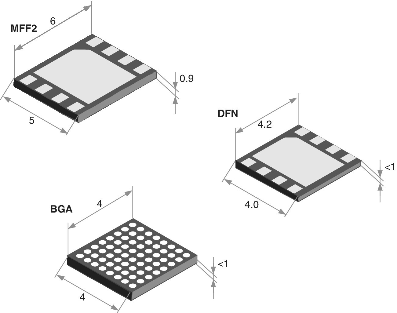
Figure 4.11 Some examples of the physically embedded SEs. At present, the MFF2 is the only standardized variant of embedded UICC. The smallest ones are typically based on wafer‐level which can be very small in volume, such as the WLCSP which can measure, e.g., 2.7 × 2.5 × 0.4 mm3, depending on each chip manufacturer’s own specifications
In addition to the physical element, whether it is a traditional removable form factor or an embedded element, there are also active investigations and discussions on SW‐based UICC which sometimes is referred to as ‘soft SIM’. The completely SW‐based subscription such as the purest form of the HCE, compared to the HW‐based SE such as UICC is discussed later. Also, the combination of the traditional UICC security and SW‐based solution such as tokenization is feasible, as well as solutions ‘in‐between’ such as HW‐based security located apart from the UICC as in TEE.
For some practical solutions in the automotive field, the European Commission is basing the in‐vehicle emergency call service, eCall, on the eUICC. In fact, new cars in the European Union need to comply with the eUICC‐based eCall as of 2015 which ensures the instant connectivity between the car and the emergency services.
4.7 Other Card Types
4.7.1 Access Cards
A widespread use case for smartcards is access. Both contact cards and contactless cards are used for this purpose to serve as proof to open doors and access information systems. A growing business area is public transport, where the cards can facilitate the fluid entrance and exit of customers. More detailed descriptions of the most common solutions is presented in Chapter 5.
4.7.2 External SD Cards
In addition to SIM/UICC and embedded SE, the SE can also be provided by an external SD card. It basically refers to the SE which a service provider owns instead of an MNO. The microSD SE can be physically a HW solution with an integrated antenna for the wireless (NFC) environment and respective NFC capabilities built in, or a solution without antenna. For the microSD without an antenna but requiring external NFC capabilities, a separate antenna connection is required.
For a microSD, which is issued and owned by an external service provider such as a bank, there are basically no specific roles for MNO or OEM manufacturers. In fact, security, issuance and distribution of the SE is the responsibility of the service provider. This use case is feasible because a variety of mobile devices come with an integrated microSD slot. It should be noted, though, that the location and design of the slot does have an impact on NFC field strength and thus on the reading distance between the NFC antenna and respective reader if the antenna is built within the microSD. In order to cope with the requirements of the minimum NFC reading distance in these cases, the device manufacturers should ideally take this into account, although there are no guaranteed processes for aligning the external microSD card functionality with any of the devices supporting it as for NFC requirements.
4.8 Contactless Cards
4.8.1 ISO/IEC Standards
ISO/IEC 14443‐1:2008 defines the physical characteristics of Proximity ICCs (PICCs), commonly known as proximity cards, or NFC cards. It is used in conjunction with other parts of ISO/IEC 14443. The set of ISO/IEC 14443 specifications have A, B and C variants, each indicating chip manufacturers. Parameter A refers to NXP (Philips) chips, C to Sony chips while B indicates the chip is from other manufacturers.
The proximity cards are based on some variant of RFID technology between the card and the reader so that the card is not inserted physically into the reader. The cards can be of simple read‐only variants such as the ones meant for accessing buildings. These variants may have only limited memory. The RF of these variants may be based on, e.g., 125 MHz frequency band, or 860–960 MHz for the 2G Ultra High Frequency (UHF) cards.
The more complete contactless cards are capable of reading and writing. The communication link is on 13.56 MHz frequency as defined by ISO/IEC 14443 standard. An early use case of this category were transportation applications for real‐time value consumption and reloading, which did require the highest security level as the wallet value was not considered particularly significant. These cards typically have protected memory types. In addition to the transport applications, they are also increasingly popular for storing retail value as the cards can provide faster transaction times yet maintain the transaction processing revenues.
4.8.2 NFC
In the modern contactless environment, the NFC‐enabled cards are based on the ISO 14443 standard. They use the physical radio interface at 13.56 MHz frequency. The SWP is defined between the UICC and NFC chip, both residing in the user equipment. The SWP is an interface between the CLF and the UICC. It is, in fact, a contact‐based protocol which is used for contactless communications.
The NFC is a short‐range wireless communication technology which enables the exchange of data between two entities such as hand‐held mobile devices and payment transaction readers. The technology is based on the high‐frequency radio interface that provides functional connections within a distance of about 10 cm between the NFC‐enabled devices, although the more precise requirement for the maximum distance depends on the entity, some payment certificates requiring possibly relaxation for the distance down to 4 cm. The maximum practical distance depends on the specifications as well as on the additional requirements which may be tighter for operators and credit card companies.
The NFC is based on the extension of the ISO/IEC 14443 proximity card standard referred to as RFID. Nevertheless, it should be noted that the NFC is not the same as RFID. Even if NFC and RFID do include common functionalities, the RFID is about small and economical tags that are readable within certain distances wirelessly. One of the examples of RFID is warehouse inventory tagging which provides instant information about the number of items, their types and characteristics that are found within that specific spot. Instead, NFC is about point‐to‐point two‐way communications between NFC devices which can be physical, e.g., computers, cell phones, laptops and PDAs.
NFC combines the interfaces of a smartcard and a reader into a single device. The NFC device can communicate with both existing ISO/IEC 14443 smartcards and readers and other NFC devices, and is thereby compatible with the existing contactless infrastructure which is already in use for public transportation and payment. In practice, NFC is primarily used in mobile devices although there are various NFC‐enabled devices on the market. Some of the typical use cases of NFC include the connecting of electronic devices according to the peer‐to‐peer data exchange concept, accessing digital content according to reader/writer concept and executing contactless transactions according to the card emulation concept. Figure 4.12 presents some high‐level NFC use cases.
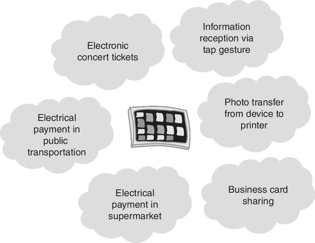
Figure 4.12 Typical use cases for NFC
The use cases can be related, among a vast amount of the possibilities, to the following: enhancements to loyalty programmes (by tapping a loyalty card, e.g., in an airport), electrical format of offer coupons, content gathering and transferring, access card to physically closed locations, assets management, reporting and for making connections.
NFC development is taken care of by the NFC Forum. In addition to the specifications, it also follows up the implementation of the standards. The NFC Forum was established in 2004, and the number of participating members has grown significantly ever since. The mission of the NFC Forum is to promote the use of NFC technology by developing standards‐based specifications that ensure interoperability among devices and services. The practical ways of work include encouraging the development of products using NFC Forum specifications, educating the global market about NFC technology and ensuring that products claiming NFC capabilities comply with NFC Forum specifications.
NFC readers and devices are basically always powered on when they function. They rely on a battery or an external power source. The readers need to be able to create an electromagnetic field that is utilized for the radio transmission. The reader is active as soon as it produces an RF field. The tag normally has no power. It gets a sufficient amount of energy via the nearby RF field, and can thus respond via a carrier modulation which is one form of a passive communication. Since the tags are not able to activate radio channels, two tags cannot communicate with each other, unlike NFC devices.
NFC can be divided into the following features:
- Tag reading for telephone numbers, URLs and visit cards. Examples for tag readers include calling a taxi and reading bus stop time schedules.
- Easy setup, including Bluetooth headset and other accessory pairing by tapping the tag.
- Sharing of photo or other contents from a hand‐held device to another phone or to a digital photo frame by touching it. As soon as the initiation has been done, the actual transfer of the contents happens via Bluetooth.
- Payment and ticketing can be applied in a similar manner as is the case for credit cards and digital bus tickets. The possibilities for the practical solutions are actually endless. It should be noted that payment requires a relatively complicated ecosystem with middleware SW and respective APIs, adaptation such as SWP as well as a HW platform such as NFC chip and antenna, UICCs, OTA, TSM, purchase readers and a set of wallet and payment applications and midlets by operators and credit card companies. In addition, the payment institutes and operators require certificates such as EMVCo, MasterCard Certification and Visa Certification. The NFC Forum has its own certificate for these purposes.
Chapter 5 discusses further NFC, and more information about the NFC technical releases of the SIMalliance can be found in Ref. [32]
4.9 Electromechanical Characteristics of Smartcards
4.9.1 HW Blocks
Figure 4.13 outlines the main HW blocks of the UICC. The main block is the CPU which is assisted by the NPU. The OS resides in ROM while the operating memory is formed by RAM. The EEPROM is a non‐volatile memory block that is used for modifying data like phonebook [3].
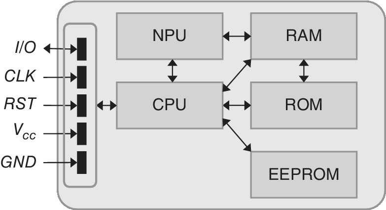
Figure 4.13 The block diagram of the UICC
Physically, there are either six or eight contacts on the UICC as summarized in Figure 4.1. Of these, not all are necessarily used for the mobile communications system. The underlying chip module consists of a die and housing. The combination of these forms the UICC.
4.9.2 Memory
The type of EEPROM dictates the writing rate and the maximum useful write cycles. Smartcard vendors personalize UICCs for different consumer markets like MNOs, industrial and automotive users. The useful lifetime of the SIM card may be around 2–3 years for the consumer space due to the relatively frequent change of the devices, whereas the industry and automotive grade UICCs may require a useful lifetime of 10–17 years.
The lifetime of the UICC is largely dictated by the maximum number of write cycles and by the tolerance for the temperature ranges and other environmental conditions. The UICC may also include additional functionalities like automatic error detection and recovery which works dynamically by reallocating the active writing areas and deactivating the non‐functional areas of the chip. Furthermore, there may be value‐added services provided by applets that are meant for monitoring the performance of the card during its lifetime and reporting possible problems in wearing of the memory, to indicate if the useful lifetime is being reached too soon. These solutions are especially useful for the automotive industry and other critical environments to indicate the need for a new SIM card beforehand as part of the next maintenance and thus avoiding extra customer visits.
The first SIM cards were limited in memory size. A set of 7 kB ROM, 3kB EEPROM and 128 byte RAM together with 8‐bit CPU was a typical setup. This was sufficient in the initial phase of the GSM, but it clearly soon became a limiting factor for user experiences along with more demanding requirements such as the maximum number of stored contacts. Along with the development of CPU and memory technologies, smartcards have also evolved. Furthermore, the initial embedding of OS to ROM is not an optimal solution as it leaves unused memory space if the OS size does not coincide with the maximum available ROM size. More advanced variants are based on flash memory which is gradually replacing the older memory structures in current markets. Smartcard chips are also going towards single chip solutions with currently about 1–2 MB size, accompanied with some hundreds of kB of flash memory.
4.9.3 Environmental Classes
Ref. [11] details the environmental requirements for M2M UICCs. The main categories are indicated by the letters T (operational and storage temperature), M (moisture), H (humidity), C (corrosion), V (vibration), F (fretting corrosion), S (shock), R (data retention time) and U (minimum updates). Table 4.3 summarizes the environmental classes for the M2M UICCs, and Table 4.4 summarizes their required key values.
Table 4.3 The environmental classification; the main categories for M2M UICCs
| Class | Description |
| T | M2M UICC performance for operational and storage temperature. Support of a given temperature range for an M2M UICC operation implies that the M2M UICC shall withstand (1) 500 temperature cycles within the full supported range; (2) 2 cycles per hour. Testing temperature cycling shall be in accordance with JESD22‐A104 as presented in [13] |
| M | M2M UICC performance for moisture/reflow conditions that may be experienced during the manufacturing of the M2M communication module |
| H | M2M UICC performance in humid conditions |
| C | M2M UICCs shall be able to pass the salt atmosphere test according to JESD22‐A107 [16] The conditions CA…CD refer to the duration of exposure to the salt atmosphere |
| V | M2M UICC performance in vibrating conditions |
| F | Fretting corrosion; M2M UICC performance when in a connector |
| S | M2M UICC susceptibility to shock |
| R | M2M UICC's ability to retain data over time. The data retention time property shall be able to fully operate with no loss of stored information over a required time as indicated in the class value, from the time of manufacture. Loss of information due to multiple erase/write cycles is excluded from this property |
| U | M2M UICC's expected minimum number of UPDATE commands, as specified in TS 102 221, supported for specified files, which are indicated as ‘high’ in the update activity field [12] The update of the specified number of file(s) per class value must happen without failure. Loss of information due to time factors is excluded from this property |
Table 4.4 UICC environmental classes and required values
| Class | Description | M2M UICC |
| TS | Operational and storage temperature, standard temperature range | −25 °C… + 85 °C |
| TA | Operational and storage temperature, class A specific UICC environmental conditions | −40 °C… + 85 °C |
| TB | Operational and storage temperature, class B specific UICC environmental conditions | −40 °C… + 105 °C |
| TC | Operational and storage temperature, class C specific UICC environmental conditions | −40 °C… + 125 °C |
| MA | Moisture/Reflow conditions, according to IPC/JEDEC J‐STD‐020D as presented in [14] | (1) Classification temperature (Tc) of 260 °C supporting Pb‐free process; (2) Moisture Sensitivity Level 3; (3) Pb‐free assembly reflow profile class |
| HA | Humidity, high | Shall support the high humidity condition as specified in TS 102 221 for UICC environmental conditions [15] |
| CA | Corrosion, condition A | Test condition A as specified in JESD22‐A107 [16] |
| CB | Corrosion, condition B | Test condition B as specified in JESD22‐A107 [16] |
| CC | Corrosion, condition C | Test condition C as specified in JESD22‐A107 [16] |
| CD | Corrosion, condition D | Test condition D as specified in JESD22‐A107 [16] |
| VA | Vibration, automotive | Shall be able to pass the variable frequency vibration tests according to JESD22‐B103 [17] |
| FA | Fretting Corrosion | This item is for further study by ETSI |
| SA | Shock, automotive | Shall be able to pass the mechanical shock tests according to JESD22‐B104 [18] |
| RA | Data Retention time, 10 years | Shall be able to fully operate with no loss of stored information over a 10‐year period from the time of manufacture |
| RB | Data Retention time, 12 years | Shall be able to fully operate with no loss of stored information over a 12‐year period from the time of manufacture |
| RC | Data Retention time, 15 years | Shall be able to fully operate with no loss of stored information over a 15‐year period from the time of manufacture |
| UA | Minimum Updates, 100,000 | Minimum of 100,000 UPDATE commands without failure |
| UB | Minimum Updates, 500,000 | Minimum of 500,000 UPDATE commands without failure |
| UC | Minimum Updates, 1,000,000 | Minimum of 1,000,000 UPDATE commands without failure |
As can be seen from Table 4.4, there is a codification system developed for distinguishing the environmental performance capabilities of UICCs. It is based on a string of two characters which can be mapped onto the environmental property. These strings represent environmental property types accordingly. This two‐character string represents the environmental performance in terms of the value range as seen in Table 4.4 in such a way that the first character stands for environmental property and the second indicates the level.
In practice, if the M2M UICC does not meet the level specified in Ref. [11] for a particular environmental property, it shall not be present in the string representing its environmental performance. There is no defined order for the environmental properties.
Ref. [23] sets the requirements for the consumer UICCs. It states that the standard temperature range for storage and full operational use shall be between −25 °C and +85 °C, but the support of specific UICC environmental conditions is optional for the UICC. Thus, the support of an extended temperature range is optional for the UICC. If supported, class A indicates the ambient temperature range of −40 °C to +85 °C while class B sets the limits to −40 °C to +105 °C, and class C to −40 °C to +125 °C. Furthermore, the extended humidity conditions are optional for the UICC. If the UICC supports the extended humidity, the limits are set based on the following environmental conditions for operation and storage in temperature of 85 °C, for the relative humidity from 90% to 95% while the duration is 1000 hours.
4.10 Smartcard SW
4.10.1 File Structure
ISO/IEC 7816 based cards have a standardized file structure. This applies to the SIM/UICC cards of mobile communications systems as well as to bank cards, transport cards and other environments that rely on the ISO/IEC 7816 smartcards.
After the initial SIM cards were utilized for the GSM networks, the 3G environment brought along extensions to the supported systems and functionalities of the SIM in form of the UICC. It contains different files, including the ones needed for the support for telecommunications. The UICC is a secure token that acts as part of the secure communications chain in 3GPP mobile networks.
The mobile telecommunications related files of the UICC are in effect applications that are able to support different radio access networks, and are referred to as Network Access Applications (NAAs). The UICC may thus contain one of various radio access networks according to the preferences of the MNO, i.e., the owner of the UICC. The GSM/GPRS SIM application manages the ETSI/3GPP 2G communications, i.e., it is the USIM in a 2G context, while the UMTS/HSPA can be managed via the USIM for a 3G context. For the LTE systems, the USIM includes LTE files that are specified by 3GPP in TS 31.102 as of Release 8. Figure 4.7 clarifies the idea of the NAAs. There may also be support for CDMA networks (1xRT, EVDO, HRDP, eHRDP etc.) via CSIM applications.
The UICC contains subscription data, including parameters that are stored in the file system of the UICC and used in authentication. The UICC also contains the algorithm for the radio interface encryption and decryption. This algorithm is also stored in the AuC of the 3GPP network, and is never exposed outside of the UICC or AuC. The UICC may also contain various applets that are nowadays based on Java. The benefit of Java is the interoperability and fluent adaptation of new applets by card manufacturers as well as by third parties.
The smartcard consists of an MF, DFs and EFs in a hierarchical way as shown in Figure 4.14. As an example, one of the dedicated files may be ‘3G’ which contains related information for supporting the complete 3G services including the encryption keys. As Ref. [23] defines, an Application DF (ADF) is a particular DF that contains all the DFs and EFs of a single application while the general DF allows for a functional grouping of files. It can thus be the parent of a DF and/or EF, and the DF is referenced by a file identifier. Figure 4.15 depicts the principle as interpreted from Ref. [23].
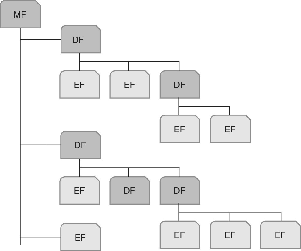
Figure 4.14 The overall principle of the file structure of the smartcard
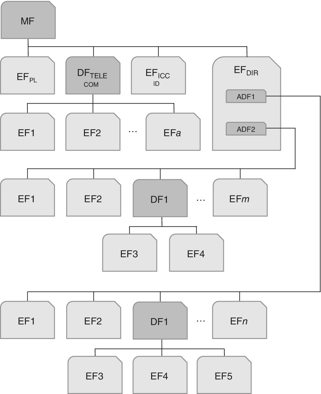
Figure 4.15 The principle of ADFs
The length of the files are typically fixed size and they are addressed by a 16‐bit file‐ID (FID) which is typically divided into DF and EF. There is only one MF per smartcard, and its FID is standardized to 0x3F00. The standardized file types are listed in Table 4.5.
Table 4.5 File types of smartcards
| File type | Description |
| Transparent | Binary file |
| Linear Fixed | Has n records of fixed length |
| Linear Variable | Has n records of different lengths, yet the length of each one is fixed |
| Cyclic | This is a Linear Fixed file type so that the oldest records are overwritten |
| Execute | Special type of transparent file |
4.10.2 Card Commands
The smartcard commands are defined in the ISO standards. In addition, there may be provider‐specific proprietary commands. Typically, the OS of the card is vendor‐specific. The modern smartcard is based on Java so the respective Java applets are by default interoperable. Nevertheless, the applets that rely on OS‐specific functions are typically vendor‐specific, although it may be possible to use converters to adapt some applets between different card vendors.
Table 4.6 summarizes some of the standardized key commands. They include general commands as well as commands related to access control, authentication, encryption, electronic purse instructions and instructions specific for applications. The access control can be based on the PIN code or Chip Holder Verification (CHV), while the authentication and encryption are based on internal network functionality for challenge and response as described in Chapter 2.
Table 4.6 Some of the key commands of the SIM/UICC
| Command | Principle |
| Create, Select, Delete File | General commands |
| Read, Write, Update Binary | General commands |
| Erase Binary | General commands |
| Read, Write, Update Record | General commands |
| Append Record | General commands |
| Increase, Decrease | General commands; applies to Cyclic File, changing the current position |
| Verify CHV | Access control‐related command |
| Change CHV | Access control‐related command |
| Unblock CHV | Access control‐related command |
| Enable, Disable CHV | Access control‐related command |
| Internal Authenticate | The card is authenticated to the terminal |
| External Authenticate | The terminal is authenticated to the card |
| Encrypt, Decrypt | Encryption‐related commands |
| Sign Data, Verify Signature | Encryption‐related commands |
| Initialize, Credit, Debit | Electronic purchasing |
It should be noted that ISO‐7816 provides the commands, but the actual implementation is left open for vendor implementation.
4.10.3 Java Card
As a practical environment for the NFC UICC, Ref. [21] dictates that it needs to be compliant with the (U)SIM Java Card Platform Protection Profile. If the NFC UICC needs to be certified at EAL4+, it must use ISO/IEC 15408 CC against the (U)SIM Java Card Platform Protection Profile.
4.11 UICC Communications
The SIM/UICC communicates via the interface with the attached equipment, i.e., handset, laptop, mobile tablet device or other portable device with integrated cellular connectivity. It contains the same type of functionality as a smartcard reader, but substantially extends the messaging between the card and the device.
4.11.1 Card Communications
The UICC communications are based on secure channels which ensures the secure communication between the smartcard and external world (card reader and other entities wanting to communicate with the card). The respective secure channel protocols are the following, based on the definitions of ETSI and the GlobalPlatform [27,28].
- SCP01 refers to a deprecated symmetric key crypto‐system [28].
- SCP02 refers to the symmetric secure channel protocol based on Triple‐DES [28].
- SCP03 refers to the asymmetric secure channel protocol based on AES [30]. There is also a further modified variant of the SCP03, referred to as SCP03t [35].
- SCP10 refers to the asymmetric key crypto‐system [28].
- SCP80 refers to the OTA remote secure channel protocol as defined by ETSI [24].
- SCP81 refers to the OTA remote secure channel based on SSL/TLS [29]. As ETSI TS 102 267 states, an application can open a connection to a remote server based on SCP81. The security for data exchange is provided by TLS. The HTTP protocol is used on top of TLS to provide encapsulation of the data. TCP/IP transport is provided by the BIP as defined in ETSI TS 102 223 or a direct IP connection as specified in ETSI TS 102 483 [29].
The overall secure communications principle for the UICC is described in Ref. [24,25,31. The communications between the smartcards such as the UICC and the external world takes place via the Card Content Management (CCM). It contains the loading, installation, personalization, extradition and deletion functions [26]. The communications are based on APDUs. There are two types of APDUs: Command APDU and Response APDU, as depicted in Figure 4.16.
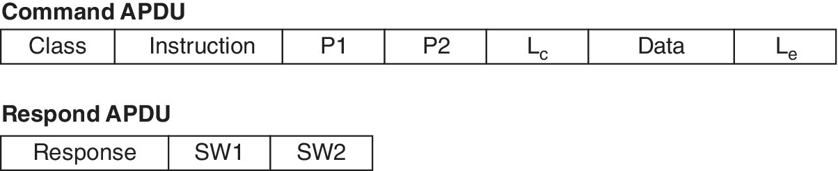
Figure 4.16 The format of the Command and Response APDU
The command APDU contains fields for Class of Instruction (CLA), which include category, SM and channel), instruction (INS), parameters 1 and 2 (P1, P2), length of the command data (Lc), command data and length of the expected response (Le).
The response APDU contains fields SW1 and SW2. Table 4.7 presents a snapshot of the responses from the card [22]. The response indicates the overall topic (SW1) and a more specific description of the response (SW2) for the normal and faulty behaviours. The APDU responses are used to ensure the correct updates of the card SW like the OS, and are useful in troubleshooting if misbehaviour is noted.
Table 4.7 An example of the SIM/UICC card response messages. The complete list can be found in ISO/IEC 7816‐4 documentation
|
Response (SW1 | SW2) |
Description |
| 61 | xx | Response bytes still available; Command successfully executed; xx bytes of data available and can be requested using GET RESPONSE |
| 62 | 81 | State of non‐volatile memory unchanged | Part of returned data may be corrupted |
| 63 | 85 | State of non‐volatile memory changed | Secured transmission not supported |
| 64 | 01 | State of non‐volatile memory unchanged | Command timeout |
| 65 | 81 | State of non‐volatile memory changed | Memory failure |
| 68 | 82 | Functions in CLA not supported | Secure messaging not supported |
| 69 | F0 | Command not allowed | Permission denied |
| 6A | F0 | Wrong parameter(s) P1‐P2 | Wrong parameter value |
| 90 | 00 | OK |
The card vendors and other stakeholders involved in the testing and troubleshooting of the SIM/UICC cards typically have a set of tools that can be utilized to monitor the card responses, as well as other communications between the card and reader. The APDUs are transmitted by Transmission Protocol Data Units (TPDUs) which are defined in ISO/IEC 7816‐3. The most popular protocols in this domain are T = 0 (byte‐oriented protocol), T = 1 (block‐oriented protocol) and T = CL (contactless protocol).
4.11.2 Remote File Management
The SIM/UICC can be managed either locally by connecting a cable between reader and the device. Anther option is to manage the cards OTA. This item includes Remote Application Management (RAM) and Remote File Management (RFM). RAM and RFM, as defined in ETSI TS 102 226 and 3GPP TS 31.116, respectively, can be performed using either the CAT‐TP mechanism or RAM/RFM over HTTPS mechanism, as defined in ETSI TS 102 225, and 3GPP TS 31.115 for PUSH SMS security and in ETSI TS 102 127.
As a practical example of the NFC UICC environment, Ref. [21] details respective requirements stating that the use of RAM/RFM over HTTPS shall be done as defined in ETSI TS 102 225 and 3GPP TS 31.115 for PUSH SMS security, as well as ETSI TS 102 226 and GlobalPlatform CS V2.2 Amendment B. The use of CAT‐TP or RAM/RFM over HTTPS may differ between regions, which needs to be taken into account in the service provider interoperability considerations, so Ref. [21] also includes instructions for use by different MNOs, suggesting that at least one of the two transport protocols referenced in the document needs to be implemented by the MNOs. It should be noted that for small management operations, the SMS OTA is still allowed.
References
- [1] Triple SIM. Three SIM cards in one: 2FF, 3FF, and 4FF. Whitepaper. Giesecke & Devrient, 2014. http://www.gi‐de.com/gd_media/media/documents/brochures/mobile_security_2/cste_1/Triple_SIM.pdf (last accessed 7 December 2014).
- [2] History of SIM cards. http://www.timetoast.com/timelines/cell‐phones‐by‐whittney‐williams‐8th‐period (last accessed 7 December 2014).
- [3] Vedder, D. K. The UICC; The security platform for value addedservices. Sophia Antipolis, France. 4th ETSI security WS. 13‐14 January 2009.
- [4] ISO 7816 introduction. http://www.smartcardsupply.com/Content/Cards/7816standard.htm (accessed 24 January 2015).
- [5] Smartcard basics. http://www.smartcardbasics.com/smart‐card‐standards.html (accessed 24 January 2015).
- [6] Elaheh Vahidian. Evolution of the SIM to eSIM. Master’s thesis. Department of Telematics, Norwegian University of Science and Technology, Trondheim. January 21, 2013. 90 p.
- [7] SFR. (U)SIM Java Card Platform Protection Profile. Basic and SCWS Configurations. Evolutive Certification Scheme for (U)SIM cards. PU‐2009‐RT‐79‐2.0.2. June 17, 2010. 85 p.
- [8] Trusted Labs, Guide de composition CC entre plateformes certifies et applications sensibles, CP‐2007‐RT‐407‐3.0.
- [9] JP. Wary, M. Eznack, C. Loiseaux, R. Presty. Developing a new Protection Profile for (U)SIM UICC platforms. ICCC 2008, Korea, Jiju, September 2008. 18 p.
- [10] Secrétariat général de la défense et de la sécurité nationale. Agence nationale de la sécurité des systèmes d'information. Certification Report ANSSI‐CC‐PP‐2010/05. (U)SIM Java Card Platform Protection Profile/SCWS Configuration (ref.PU‐2009‐RT‐79, version 2.0.2). 2009. 15 p.
- [11] ETSI TS 102 671, V9.0.0, April 2010. Technical Specification, Smartcards; Machine to Machine UICC; Physical and logical characteristics, Release 9. 21 p.
- [12] ETSI TS 102 221, V11.0.0, June 2012. Technical Specification; Smartcards; UICC‐Terminal interface; Physical and logical characteristics, Release 11. 181 p.
- [13] JEDEC JESD22‐A104D. Temperature Cycling.
- [14] IPC/JEDEC J‐STD‐020D.1. Moisture/reflow sensitivity classification for non‐hermetic solid state surface mount devices.
- [15] ETSI TS 102 221. Smartcards; UICC‐terminal interface; Physical and logical characteristics.
- [16] JEDEC JESD22‐A107B. Salt atmosphere.
- [17] JEDEC JESD22‐B103B. Vibration, variable frequency.
- [18] JEDEC JESD22‐B104C. Mechanical Shock.
- [19] Mobile/NFC Security Fundamentals Secure Elements 101. Smartcard Alliance Webinar, March 28, 2013. 42 p.
- [20] SIMalliance. Smartcard Web Server; How to bring operators’ applications and services to the mass market. February 2009, 18 p.
- [21] GSM Association SGP.03.
- [22] APDU response list. https://www.eftlab.com.au/index.php/site‐map/knowledge‐base/118‐apdu‐response‐list (accessed 28 November 2015).
- [23] ETSI TS 102 221 V8.2.0 (2009‐06). Smartcards; UICC‐Terminal interface; Physical and logical characteristics (Release 8). 174 p.
- [24] ETSI TS 102 225 V9.0.0 (2010‐04). Smartcards; Secured packet structure for UICC based applications (Release 9). 22 p.
- [25] ETSI TS 102 224 V8.0.0 (2008‐10) Technical Specification, Smartcards; Security mechanisms for UICC based Applications ‐ Functional requirements (Release 8). 19 p.
- [26] ETSI TS 102 226 V9.2.0 (2010‐04) Technical Specification, Smartcards; Remote APDU structure for UICC based applications (Release 9). 43 p.
- [27] Bharat Bhanjana. Secure Communication between Card and Server. International Journal of Scientific and Research Publications, Volume 5, Issue 8, August 2015 ISSN 2250‐3153
- [28] GlobalPlatform. GlobalPlatform Card Specication,version 2.2. March, 2006.
- [29] Remote Application Management over HTTP. GlobalPlatform Specication, September 2006.
- [30] GlobalPlatform Card Technology. Secure Channel Protocol 03. GlobalPlatform Public Release, September 2009.
- [31] Smartcards; Secured Packet Structure for UICC based Applications (Release 6). ETSI TS 102 225 (V6.8.0), April 2006.
- [32] SIMalliance, NFC releases, 25 December 2015. http://simalliance.org/nfc/nfc‐technical‐releases/ (accessed 25 December 2015).
- [33] Remote Provisioning Architecture for Embedded UICC Technical Specification, Version 2.1. GSMA, 2 November 2015. 297 p.
- [34] ETSI TS 103 383. Smartcards; Embedded UICC; Requirements Specification (Release 13), V. 13.0.0, October 2015. 29 p.
- [35] Embedded UICC Protection Profile, Version 1.1. GSMA, 25 August 2015. 127 p.
- [36] Phone book management with ISO 7816 part 7. 3GPP TSG‐T3, Document T3‐99167. Miami, June, 14th to 16th, 1999. 22 p.
- [37] Protection Profile — Secure Signature‐Creation Device, Type3. Prepared by ESIGN Workshop Expert Group F for CEN/ISSS. Version: 1.05, EAL 4+. 25 July 2001. 67 p.
- [38] Proposed Correspondence to EP‐SCP calling for establishment of a formal liaison to promote RUIM global harmonization. TSG correspondence of the 3GPP2, TSG‐C, October 23, 2000. 3p.
- [39] ETSI TS 100 812‐2, V2.4.1. Terrestrial Trunked Radio (TETRA); Subscriber Identity Module to Mobile Equipment (TSIM‐ME) interface; Part 2: Universal Integrated Circuit Card (UICC); Characteristics of the TSIM application. 3 August 2005.