
Chapter 17
Using Dynamic Blocks
Blocks are a great way to create and store ready‐made symbols. They can be a real time‐saver, especially when you have assemblies that you use often. Earlier in this book you learned how to create a basic, no‐frills block. When you understand the basics of block creation, you can begin to work with dynamic blocks.
Dynamic blocks have properties that you can modify using grips. For example, you can create a dynamic block of a door and then easily grip‐edit its size and orientation. Or you can use a single block to represent several versions of a similar object. You can have a single block of a bed that can be modified to show a double, queen‐sized, or king‐sized shape.
In this chapter, you'll explore the use of dynamic blocks through a series of exercises. Each exercise will show you a different way to use dynamic blocks. This will help you become familiar with the methods involved in creating dynamic blocks. You'll start by looking at the Block Editor, which in itself makes editing blocks much easier. Then you'll be introduced to the tools used to create dynamic blocks.
Exploring the Block Editor
![]() Before you start to add dynamic block features to blocks, you'll want to get familiar with the Block Editor. The Block Editor offers an easy way to make changes to existing blocks, and as you'll see a bit later, it's also the tool that you'll use to give your blocks some additional capabilities.
Before you start to add dynamic block features to blocks, you'll want to get familiar with the Block Editor. The Block Editor offers an easy way to make changes to existing blocks, and as you'll see a bit later, it's also the tool that you'll use to give your blocks some additional capabilities.
Opening the Block Editor
As an introduction to the Block Editor, you'll make changes to the now familiar unit plan from earlier tutorials. Start by editing the Kitchen block in the unit:
- Open the
Unit.dwgfile that you saved from earlier exercises, and freeze the Notes layer. If you have been working in metric or did not create the file earlier, you can also use the17‐unit.dwgfile. - Double‐click the kitchenette in the plan to open the Edit Block Definition dialog box (see Figure 17.1). Notice that all the blocks in the drawing are listed in the dialog box and that the Kitchen block is highlighted. You also see a preview of the block in the preview group.
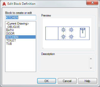
FIGURE 17.1 The Edit Block Definition dialog box
- With the KITCHEN block name selected, click OK. You see an enlarged view of the kitchenette in the drawing area with a light gray background (see Figure 17.2).
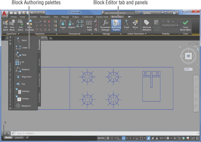
FIGURE 17.2 The Block Editor and its components
The gray background tells you that you're in the Block Editor. You'll also see the Block Editor tab along the top of the drawing area and the Block Authoring palettes, as shown in Figure 17.2.
Take a moment to look over the panels and tools on the Block Editor tab. This tab offers several housekeeping tools that let you open and save blocks and exit the Block Editor. You can point to each tool in the tab's panels to see its description. Figure 17.3 shows the Block Editor tab and tools.
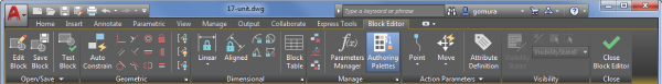
FIGURE 17.3 The Block Editor tab
Both the Block Editor tab and the Block Authoring palettes offer tools for adding dynamic block features that you'll explore later in this chapter. You may notice that the Block Editor tab contains the geometric and dimensional constraint panels that you learned about in Chapter 16, “Making ‘Smart’ Drawings with Parametric Tools.” Let's continue our look at the basic features of the Block Editor.
Editing a Block and Creating New Blocks
![]() The Block Editor lets you edit a block using all of the standard Autodesk® AutoCAD® editing tools. In the following exercise, you'll modify the kitchen sink and save your changes to the drawing:
The Block Editor lets you edit a block using all of the standard Autodesk® AutoCAD® editing tools. In the following exercise, you'll modify the kitchen sink and save your changes to the drawing:
- Delete the rectangle that represents the sink in the Kitchen block.
- Click Close Block Editor on the Block Editor tab's Close panel (see the right side of Figure 17.3).
- A message appears asking if you want to save your changes to the Kitchen block. Click Save The Changes To KITCHEN. Your view returns to the standard AutoCAD drawing area, and you can see the changes that you made to the kitchen, as shown in Figure 17.4.
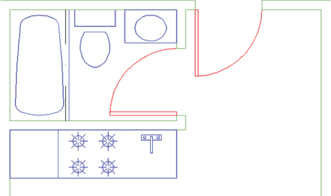
FIGURE 17.4 The unit plan with the edited Kitchen block
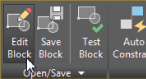
As you can see, editing blocks with the Block Editor is straightforward. In this example, you deleted part of the block, but you can perform any type of drawing or editing to modify the block. The Block Editor tab also offers other block‐saving options in its panels. You can save the block as you work by clicking the Save Block Definition button. If you need to create a variation on the block that you're currently editing, you can click the Save Block As tool on the Block Editor's expanded Open/Save panel to create a new block or overwrite an existing one with the drawing that is currently in the Block Editor.
If you want to edit a different block after editing the current one, you can click the Save Block tool on the Block Editor's Open/Save panel to save your current block and then click the Edit Block tool.
This tool opens the Edit Block Definition dialog box that you saw earlier. You can then select another block to edit or create a new block by entering a name for your block in the Block To Create Or Edit box.
Creating a Dynamic Block
![]() Now that you've seen how the Block Editor works, you can begin to explore the creation of dynamic blocks. As an introduction, you'll create a rectangle that you'll use to replace the sink in the kitchen. You'll add a dynamic block feature that will allow you to adjust the width of the sink using grips. In addition, you'll add a control that limits the size to one‐unit increments.
Now that you've seen how the Block Editor works, you can begin to explore the creation of dynamic blocks. As an introduction, you'll create a rectangle that you'll use to replace the sink in the kitchen. You'll add a dynamic block feature that will allow you to adjust the width of the sink using grips. In addition, you'll add a control that limits the size to one‐unit increments.
Start by creating a block from scratch using the Block Editor:
- Click the Block Editor tool in the Home tab's Block panel.
- In the Edit Block Definition dialog box, enter Sink in the Block To Create Or Edit box and then click OK.
 Make sure that you are on the Fixture layer, and then use the Rectangle tool on the Home tab's Draw panel to draw a rectangle that is 12 units in the x‐axis and 15 units in the y‐axis.
- Zoom into the rectangle so that your view looks similar to Figure 17.5.
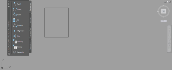
FIGURE 17.5 The rectangle for the Sink block
You could save this block now, and you'd have a simple, static block. Next, you'll add a couple of features called parameters and actions. As their names imply, parameters define the parameters, or limits, of what the dynamic block will do, and actions describe the particular action taken when the grips of the dynamic block are edited. For example, in the next section, you'll add a Linear parameter that tells AutoCAD that you want to restrain the grip‐editing to a linear direction. You'll also add a Stretch action that tells AutoCAD that you want the grip‐edit to behave like a Stretch command that pulls a set of vertices in one direction or another.
Adding a Parameter
The first parameter that you'll add establishes the base point for the block. This will let you determine the point used when inserting the block in your drawing:
- In the Block Authoring palettes, select the Parameters tab.
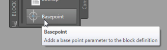
- Click the Basepoint tool, Shift+right‐click, select the Endpoint osnap, and then click the lower‐left corner of the rectangle. This is how you determine the base point, or insertion point, of a block while using the Block Editor.
Next, you'll add a parameter that will determine the type of editing that you want to add to the block. In this case, you want to be able to grip‐edit the width of the block. For that you'll use the Linear Parameter tool:
 Click the Linear tool on the Parameters tab of the Block Authoring palettes, or expand the Parameter tool (Point) on the Block Editor tab's Action Parameters panel and click Linear.
- At the prompt
Specify start point or [Name/Label/Chain/Description/Base/Palette/Value set]:Shift+right‐click and select the Midpoint osnap; then select the left side of the rectangle.
- Shift+right‐click again, select Midpoint from the Osnap menu, and select the right side of the rectangle.
- At the
Specify label location:prompt, the parameter name appears with the parameter label at the cursor. Click below the rectangle to place the label, as shown in Figure 17.6.
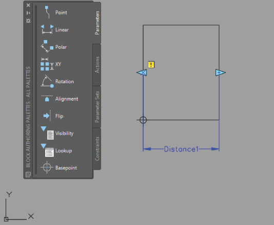
FIGURE 17.6 Placing the Linear parameter
The parameter that you just added lets you modify the block in a linear fashion. In this case, it will allow you to change the width of the rectangle. As you'll see, the locations of the parameter's arrows later become the grip locations for the dynamic block.
But just adding the parameter doesn't make the block dynamic. You need to include an action before a parameter can be used. You may have noticed the warning symbol in the parameter that you just added. It tells you that you need to take some further steps to make the parameter useful.
Adding an Action
Next, you'll add a Stretch action that will enable you to use the Linear parameter that you just added. The Stretch action will let you stretch the block horizontally by using grips. As you add the action, notice that it's similar to the Stretch command. The only difference is that you don't stretch the object; you only specify the vertices to stretch and the object you want to stretch.
Follow these steps:
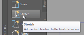
- Turn off osnaps and then click the Actions tab in the Block Authoring palettes and select Stretch.
- At the
Select parameter:prompt, click the Distance1 parameter you just created. - At the
Specify parameter point to associate with action or enter [sTart point/Second point] <Start>:prompt, point to the left‐pointing arrow. You see a red X showing the location of a parameter point.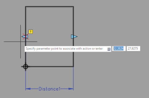
- Click the X.
- At the
Specify first corner of stretch frame or [CPolygon]:prompt, place a selection window around the entire left side of the rectangle. This selects the portion of the rectangle that is to be stretched when you grip‐edit the block. - At the
Specify objects to stretch Select Object:prompt, select the rectangle and the base point you added earlier and then press ↵ to complete your selection.
You've just added an action to the Linear parameter that you added earlier. You'll see an action icon appear below and to the right of the Distance1 linear parameter. The icon looks like the Stretch tool in the Actions tab to help you identify the action. If you hover over the icon, the parts affected by the action are highlighted.
Notice that the warning symbol is still showing. You need to add another action to the right side of the parameter because the parameter expects that you'll want to be able to grip‐edit both sides:
- Repeat the previous set of steps, but instead of clicking the left X as you did in step 4 of the preceding exercise, click the right arrow.
- Place a window selection around the right side of the rectangle (as you did around the left side in step 5 in the preceding exercise).
- At the
Specify objects to stretch:prompt, select the rectangle again.
A second action icon appears next to the first one to the lower right of the Distance1 linear parameter. This time the warning symbol disappears, telling you that you've completed the steps that you need for the parameter. You're ready to save the block and try it out:
- Click Close Block Editor on the Block Editor tab's Close panel.
- At the message asking if you want to save changes to the Sink block, click Save The Changes To Sink.
Next, insert the sink to see how it works:
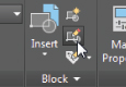
 Click the Insert tool in the Home tab's Block panel.
- Select Sink from the Insert flyout, scrolling down if you can't see it at first. The sink appears at the cursor.
- Place the block at the location shown in Figure 17.7.
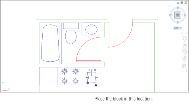
FIGURE 17.7 The Sink block in place
 Click the newly inserted sink. You see two arrows at the vertical midpoints of the block.
- Turn on Ortho mode, and click and drag the arrow on the right side of the block. The width of the block follows the arrow as you drag it. You also see the dimension of the sink as you drag the arrow.
- Enter 15↵. The width of the block changes to 15 inches from the original 12.
Although you entered a value in step 6 to change the width of the sink, you could have clicked the mouse to change the width visually. The rectangle is still a block. You didn't have to explode it to change its width. If you hover the cursor over the dynamic block grip, you see the block's width dimension.
Adding an Increment Value
You can grip‐edit your dynamic Sink block to modify its width, and as you saw in the previous exercise, you can enter a specific value for the width as well. But suppose that you'd like to limit grip movement so that the sink changes in only 1″ steps. You can set parameters to have an increment value so that grip edits are limited to a specific distance.
The following steps show how you can set up the Linear parameter of the Sink block so that the sink width can be grip‐edited to 1″ increments:
- Double‐click the Sink block. Then, in the Edit Block Definition dialog box, make sure that Sink is selected and click OK. You may need to zoom into the sink.
- Click the Linear parameter's Distance1 label, right‐click, and choose Properties.
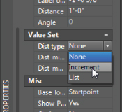
- In the Properties palette, scroll down to the Value Set group and click the Dist Type listing. The Dist Type option changes to a drop‐down list.
- Expand the list and select Increment.
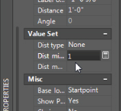
- Click in the Dist Increment text box just below the Dist Type options, and enter 1 for an increment distance of 1 inch.
- Close the Properties palette, and then click Close Block Editor on the Block Editor tab's Close panel.
- Save the changes.
- Click the Sink block to expose its grips.
- Click and drag the right arrow grip to the right. As soon as you click the grip, you'll see a set of increment marks appear indicating the increment steps for the grip. As you move the grip, the sink width jumps to the increment marks, which are 1″ apart, as shown in Figure 17.8.
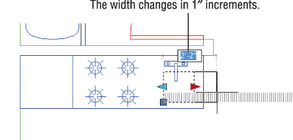
FIGURE 17.8 Grip‐editing the Sink block with the Linear parameter's increment value set to 1
- Set the width of the sink back to 12″.
In addition to an increment distance, you can set a range of movement for the Linear parameter. You may have noticed the minimum and maximum text boxes in the Properties palette in steps 3 through 5. You can enter values for these settings that define the range of movement allowed for the grip edits.
The sink exercise is a simple demonstration of how you can create and use dynamic blocks. But as you can see from the Block Authoring palettes, you can add many other parameters and actions to a block.
Editing Parameters and Actions
In the previous exercises, you inserted parameters and actions using the default settings. These settings give you default names and labels for the parameters and actions, but you can always change them later. To change the label that appears for a parameter, double‐click the label. The label will then appear in a rectangular box showing you that you can change its text.
If you want to include additional objects for an action, click the action icon to select it and then right‐click and select Action Selection Set ➢ Modify Selection Set. You can also choose Action Selection Set ➢ New Selection Set if you want to change the object of the action.
Keeping an Object Centered
Now suppose that you want to add a drain to the sink, but to make things a little more complicated, you want to make sure that the drain remains centered if the sink is widened or made narrower. You can alter the way the Linear parameter behaves so that both sides of the sink move symmetrically. Here's how it works:
- Double‐click the Sink block to open the Edit Block Definition dialog box. Make sure that Sink is selected and click OK. Make sure that you are on the Fixture layer.
- Add a 3″ diameter circle in the center of the rectangle. This circle will represent the drain (see Figure 17.9). You can use the Geometric Center Osnap to locate the center of the rectangle representing the Sink.
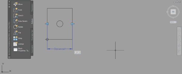
FIGURE 17.9 Adding the sink drain
- Select the Distance1 linear parameter, and then right‐click and select Properties.
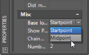
- In the Properties palette, scroll down to the bottom and look for the Base Location setting under the Misc section.
- Click the Base Location option, and then select Midpoint from the drop‐down list that appears to the right.
- Close the Properties palette.
- Click Close Block Editor in the Close panel, and save the Sink block changes.
Now try grip‐editing the block to see how the Stretch action affects the sink drain:
- Click the sink to select it.
- Click and drag the right arrow grip to the right. The drain stays centered in the sink while the two sides expand outward.
In this exercise, you changed the Base Location option for the Linear parameter, which causes the block to behave differently when you edit its grips. You can also employ a completely different method to achieve similar results. The Geometric and Dimensional panels of the Block Editor tab offer a set of tools that work in a way that's similar to how the parameters and actions with which you've worked already function. You will learn how these tools work next.
Using Constraints in Dynamic Blocks
In the sink example, you added two Stretch actions to a Linear parameter. This enabled the block to be stretched in both the left and right directions. The actions and parameters offer one way of creating dynamic blocks, but you can also use the geometric and dimensional constraints to which you were introduced in the previous chapter.
In this section, you'll turn a simple door block into a dynamic block that will allow you to resize the door to any opening. In the process, you'll learn how to apply geometric and dimensional constraints to create a dynamic block.
At first, you may think that all you need to do to resize a door is to change the scale. But when you scale the door, all of its features, including the door width, are scaled proportionally. To be very accurate, you only want to stretch the door width and scale the door swing, leaving the door thickness at the same dimension. This can be accomplished by adding two aligned dimensional constraints and a few geometric constraints to the door.
Start by opening the Door block in the Block Editor and adding the geometric constraints to the door:
 Press Esc to clear any current selections, and then click the Block Editor tool in the Home tab's Block panel.
- In the Edit Block Definition dialog box, select DOOR and then click OK.
 Click the AutoConstrain tool in the Block Editor tab's Geometric panel, and then select the rectangle representing the door, as shown in Figure 17.10. To select the door using a window, click above and to the left of the door, and then click below and to the right.
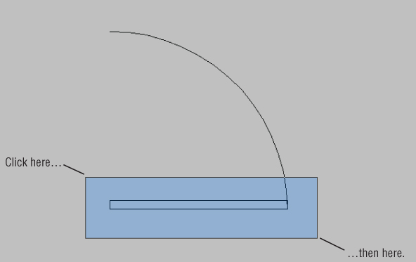
FIGURE 17.10 Select the rectangle representing the door
- Press ↵ when the door has been selected. You'll see the geometric constraint icons appear around the door.
The geometric constraints will make sure that the door maintains its rectangular shape when you apply changes to the door through the dynamic block feature. The constraints used are Parallel, Perpendicular, Coincident, and Horizontal. Note that the Coincident constraint will not show an icon unless you hover over one of the corners of the rectangle.
You'll need to add a constraint to keep the arc connected to the rectangle:
 Click the Coincident tool in the Geometric panel.
- Place the cursor near the right end of the bottom horizontal line of the rectangle.
- When you see the red circle and X marker, click.
- Place the cursor near the lower end of the arc where it meets the rectangle. When you select this end, make sure that the arc is highlighted, indicating that the arc will be selected. You may need to zoom into the location to ensure that you are selecting the correct point.
- When you see the red circle and X marker, click the mouse.
The Coincident constraint that you just added will keep the arc and rectangle connected at the bottom‐right corner of the rectangle.
Next, add a dimensional constraint. Most likely, you'll need to scale the door based only on the door opening, so place a dimensional constraint between the door hinge and the end of the door swing arc:
 Click the Aligned tool in the Block Editor tab's Dimensional panel.
- At the
Specify first constraint point or [Object/Point & line/2Lines] <Object>:prompt, point to the line at the bottom of the drawing near the left endpoint, as shown in Figure 17.11.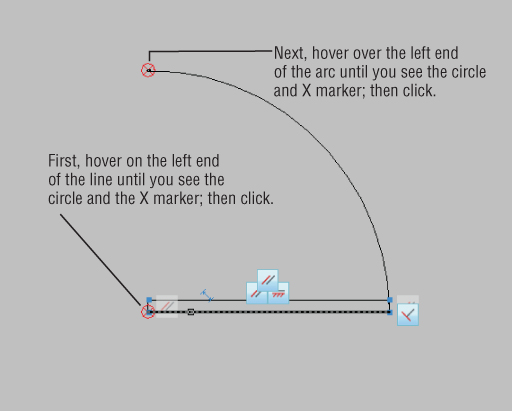
FIGURE 17.11 Select the locations for the door opening dimensional constraint
- When you see the red circle with the X appear at the left endpoint of the line, click.
- At the
Specify second constraint point:prompt, place the cursor on the top end of the arc so that you see the circle and X marker again at the left end of the arc, as indicated in Figure 17.11, and click. - At the
Specify dimension line location:prompt, place the dimension to the left of the arc (see Figure 17.12).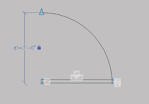
FIGURE 17.12 The aligned dimensional constraint applied to the door opening
- With the dimension highlighted, press ↵. Your drawing will look similar to Figure 17.12.
Notice that the constraint you just added is named d1. This will be an important feature in the next two constraints that you add.
Next, add another dimensional constraint to the width of the door rectangle. This time, you want the constraint to follow the door opening constraint, so instead of accepting the default value for the dimension, you'll enter the name of the first dimensional constraint:
 Click the Aligned tool again from the Dimensional panel.
- Select the left end of the bottom horizontal line again, as you did in the previous exercise (see Figure 17.13).
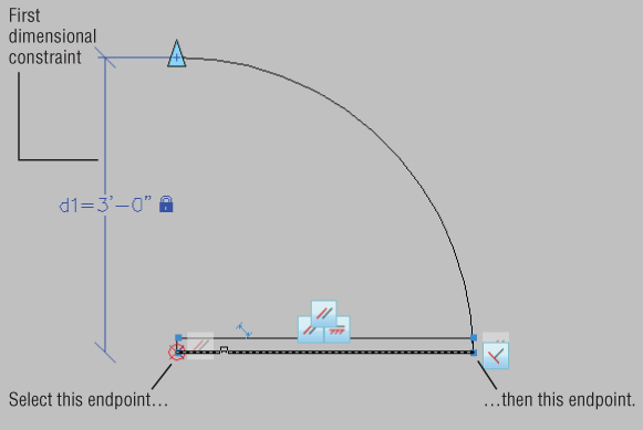
FIGURE 17.13 The door with the opening and door constraints added
- Select the right end of the bottom horizontal line, as shown in Figure 17.13.
- Place the dimension line below the door roughly the same distance away from the door as the first dimensional constraint.
- With the newly placed dimension highlighted, enter d1↵. This will cause the door rectangle to follow the dimension of the d1 door opening dimensional constraint.
Finally, add the dimensional constraint for the arc:
 Click the Radius tool in the Block Editor tab's Dimensional panel.
- Click anywhere on the arc.
- Position the Radius dimensional constraint anywhere toward the outside of the arc.
- With the radius dimension highlighted, enter d1↵. This will cause the arc to follow the dimension of the door opening dimensional constraint.
- You now have all of the constraints in place and are ready to try out your dynamic block (see Figure 17.14). Click Close Block Editor in the Close panel to save the block and return to the drawing.
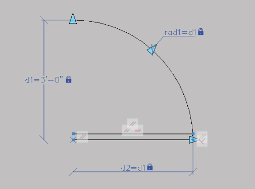
FIGURE 17.14 The door with all the constraints added
Now try out your new dynamic block by adjusting the door size:
- Pan your view so that you can see the entry door clearly, as shown in Figure 17.15.

FIGURE 17.15 The Door block with its grips exposed
- Click the door to select it. The added aligned constraint arrow appears as a grip on the right end of the Door block.
- Click the arrow grip. The length dimension becomes available for your input, and as you move the mouse, the door changes in size. Note that the thickness of the door doesn't change as you alter its width.
- Enter 24↵ to change the door width to 24″.
Notice that, although you were able to enter a door dimension directly to the block, you didn't change the door thickness when the door size changed. Only the door swing and width changed to accommodate the new door size. This is most apparent if you scale the door to a small size such as 6″ or 12″.
Adding a List of Predefined Options
Earlier, you saw how you can add an increment value set to make a dynamic block stay in a set range of sizes. You can also set up a dynamic block to offer a range of sizes in a pop‐up list. To do so, you need to employ the Block Table feature.
In the following exercise, you'll add a selectable list to the Door block to allow the door size to be selected from a list. Start by adding the block table that will allow you to define a set of predefined door dimensions:
- Double‐click the door to open the Edit Block Definition dialog box and then click OK.
 In the Block Editor tab's Dimensional panel, click the Block Table tool.
- At the
Specify parameter location or [Palette]:prompt, place the block table in the location shown in Figure 17.16.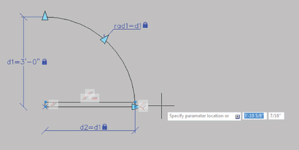
FIGURE 17.16 Placing the block table
- At the
Enter number of grips [0/1] <1>:prompt, press ↵. The Block Properties Table dialog box appears (see Figure 17.17).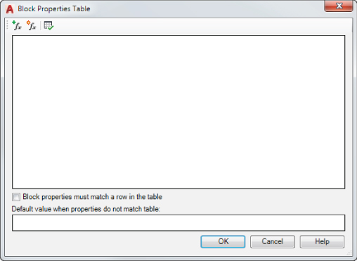
FIGURE 17.17 The Block Properties Table dialog box
 Click the Add Properties tool in the upper‐left corner of the Block Properties Table dialog box. The Add Parameter Properties dialog box appears (see Figure 17.18).
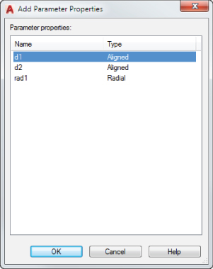
FIGURE 17.18 The Add Parameter Properties dialog box
- Click the d1 listing at the top of the Add Parameter Properties dialog box and click OK. The Block Properties Table returns with a d1 heading in the list box.
- Click just below the d1 listing; then type 12↵. You see 1′‐0″ added to the list.
- Type 18↵; 1′‐6″ is added to the list.
- Type 24↵30↵36↵. The values that you enter are added to the list in feet and inches format (see Figure 17.19).
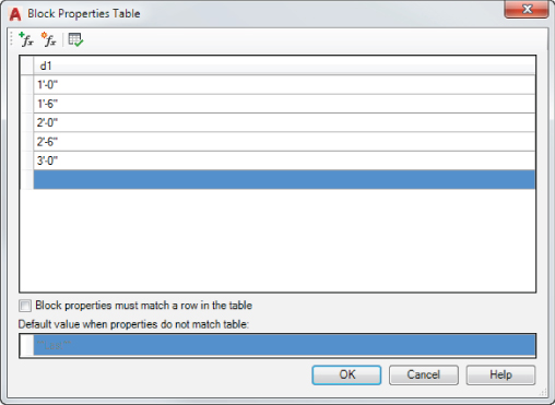
FIGURE 17.19 The Block Properties Table dialog box with the values added
- Click OK to exit the Block Properties Table dialog box.
- Click Close Block Editor in the Close panel, and save the changes to return to your drawing.
Now you can select from the door sizes in a pop‐up list:
- Click the door to select it.
- Click the down‐pointing grip below the door, as shown at the left side of Figure 17.20.
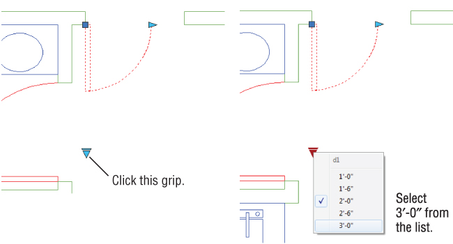
FIGURE 17.20 Selecting a door size from a list
- Select the 3′‐0″ door from the list that appears. (See the view to the right in Figure 17.20.) The door changes to a 36″‐wide door.
If at a later time you need to make changes to the list or add more dimensions, you can open the block in the Block Editor and then click the Block Table tool. The Block Properties Table dialog box will appear with the data you entered earlier. You can then make changes to the table.
In this example, you saw that you can easily add predefined sizes to the dimensional constraint that appear in a selectable list. You can also give the list a more meaningful name. Right now, when you click the grip that opens the list, you see d1 as the name. Try the following to change the name from d1 to Width:
- Double‐click the door, and in the Edit Block Definition dialog box, click OK.
- Select the d1 dimensional constraint, and then right‐click and select Properties.
- In the Properties palette, select the Name option under the Constraint group and then type Width↵. Notice that all the dimensional constraints that reference the dimension will change to show the name Width instead of d1.
- Close the Properties palette, click the Close Block Editor tool in the Close panel, and then click to save the changes in the dialog box.
- To see the change, click the down‐pointing grip below the door as you did in the previous exercise. Now you see the word Width as the heading in the list of door widths (see Figure 17.21).
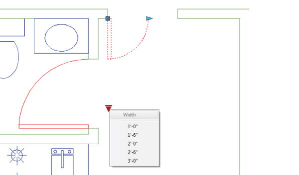
FIGURE 17.21 The list with the word Width appearing as the column title
- Save and close the file.
As you can see, you have a lot of control over the behavior of various components of the dynamic block. In the next section, you'll learn how you can control the visibility of different parts of your block.
Creating Multiple Shapes in One Block
Depending on circumstances, you may need a block to display a completely different form. For example, you might want a single generic bath that can morph into a standard bath, a corner bath, or a large spa‐style bath with jets.
Using dynamic blocks, you can hide or display elements of a block by selecting a visibility state from a list. For example, you can draw the three different bath sizes and then set up a visibility state for each size. Each visibility state displays only one bath size. You can then select a visibility state depending on the bath size that you want.
Try the following exercise to see how this works firsthand:
 Open the
 visibilitysample.dwgfile, and then click the Block Editor tool on the Home tab's Block panel.- In the Edit Block Definition dialog box, select Bathtub from the list and click OK.
You see the contents of the Bathtub block (see Figure 17.22). It's just the three existing blocks—Standard, Jetted, and Corner—inserted at the same origin.
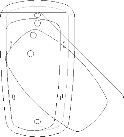
FIGURE 17.22 The Bathtub block
If you were to insert this block in a drawing, it would appear just as you currently see it, with each bathtub type overlaid on another. Next you'll see how you can add control over the visibility of each bathtub type so that only one is displayed at a time.
The first thing you need to do is to add a Visibility parameter:
 On the Parameters tab of the Block Authoring palettes, click Visibility.
- Click below the blocks to place the Visibility parameter, as shown in Figure 17.23.
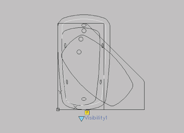
FIGURE 17.23 Adding the Visibility parameter
- Double‐click the Visibility parameter that you just added to open the Visibility States dialog box (see Figure 17.24). One visibility state, VisibilityState0, is already provided.
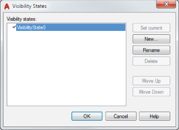
FIGURE 17.24 The Visibility States dialog box
You'll need three visibility states, one for each type of bathtub whose visibility you want to control. You've already got one, but you want a name that is more appropriate to the application:
- Click the Rename button. The existing visibility state in the list to the left becomes editable.
- Enter Standard↵. This is the visibility state for your standard bathtub.
- Click the New button to open the New Visibility State dialog box (see Figure 17.25).
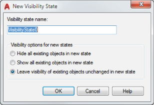
FIGURE 17.25 Adding a visibility state
- Enter Jetted in the Visibility State Name box.
- Make sure that the Leave Visibility Of Existing Objects Unchanged In New State radio button is selected, and then click OK.
- Click the New button again.
- In the New Visibility State dialog box, enter Corner in the Visibility State Name box.
- Make sure that Leave Visibility Of Existing Objects Unchanged In New State is selected, and click OK.
You've just created all of the visibility states that you need.
- Select Standard from the list in the Visibility States dialog box, and click the Set Current button. (You can also double‐click the Standard item.) A check mark appears to the left of Standard, showing you that it's now the current state.
- Click OK to exit the Visibility States dialog box.
You have the visibility states that you need, and you have the objects whose visibility you want to control. Now you need to determine which block is visible for each state.
Remember that in step 9 of the previous exercise, you made Standard the current visibility state. You'll want only the standard Bathtub block visible for this state. Do the following to turn off the other two Bathtub blocks for the current state:
- Select the Jetted and Corner blocks (see Figure 17.26).
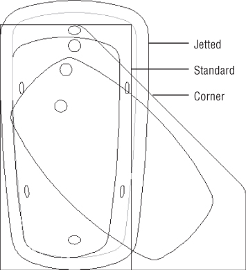
FIGURE 17.26 Locating the blocks
- Right‐click, and choose Object Visibility ➢ Hide For Current State. You can also click the Make Invisible tool on the right side of the Block Editor tab's Visibility panel.
The selected blocks disappear. They didn't go anywhere; they are just made invisible.
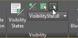
- Click the drop‐down list on the Block Editor tab's Visibility panel, and select Jetted. The hidden blocks appear.
The current visibility state is now Jetted, so you want only the Jetted block to be visible. Select the Standard and Corner blocks, and then right‐click and choose Object Visibility ➢ Hide For Current State. You can also click the Make Invisible tool from the Visibility panel. Now only the Jetted block is visible.
- On the Block Editor tab's Visibility panel, click the drop‐down list again and select Corner. All of the blocks appear.
- Select the Standard and Jetted blocks, and click the Make Invisible tool. Now only the Corner block is visible.
You've created visibility states and set up the blocks so that they appear only when the appropriate visibility state is current. Next you'll test the blocks:
- Click Close Block Editor, and save the changes that you've made.
 Click the Insert tool on the Home tab's Block panel, click More Options, and then select Bathtub from the Name drop‐down list in the Insert dialog box.
- Make sure that Specify On‐Screen is checked for the Insertion Point group and unchecked for the Scale and Rotation groups.
- Click OK, and then place the block to the right of the other three blocks.
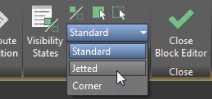
- Click the Bathtub block that you just inserted, and then click the Visibility grip (see the left image in Figure 17.27).
FIGURE 17.27 Using the Visibility grip to change the bathtub
- Select Jetted from the list. The jetted bathtub appears (see the right image in Figure 17.27).
- Click the Bathtub block again, click the Visibility grip, and select Corner. The Corner tub appears.
- Save and close the drawing.
In this example, you used a set of bathtubs, but you can use the Visibility parameter for anything that requires a different appearance. As mentioned at the beginning of this chapter, another use might be a block that contains a double, a queen‐sized, and a king‐sized bed. Going back to the door example, you can create a left‐ and right‐hand door in the same block and then use the Visibility parameter to display a left‐ or right‐hand door in the drawing. Figure 17.28 shows such a door block. The Visibility parameter has been renamed Hand in the block. When the door is inserted in the drawing, you see a list that allows you to select Left or Right.
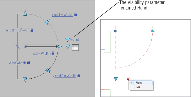
FIGURE 17.28 The Door dynamic block showing a left‐ and right‐hand door (left), and the Door block as it appears in the drawing (right)
Rotating Objects in Unison
You've seen how actions and parameters can control the behavior of a single object in a block. You can also apply actions to multiple objects so that they move or change in unison. The following example shows how you can apply more than one Angular Constraint parameter to control two objects:
- Open the
gatesample.dwgfile. In this sample file, the part that will move consists of the two non‐red objects. The red lines have been added to help facilitate the rotation feature of the block. - Double‐click the object in the drawing to open the Edit Block Definition dialog box, and then click OK. The Gate block opens for editing.
 Click the Show All Geometric Constraints tool in the Block Editor tab's Geometric panel to reveal some of the existing constraints.
You can see how this drawing has been prepared for this exercise. The non‐red parts of the drawing, which we'll call gates, are blocks that are constrained to the red lines with coincident constraints. The endpoints of the lines are constrained to the center of the arcs. The horizontal red lines are constrained to the vertical ones, also with Coincident constraints, and the vertical lines are constrained at both ends with a fixed constraint (see Figure 17.29).
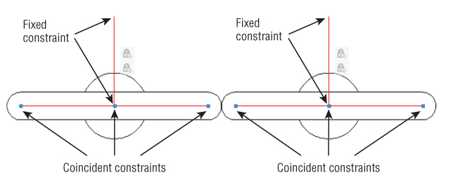
FIGURE 17.29 How the parts of the block are constrained
You'll use the red lines to define the rotation angle of the parts. The vertical line is fixed in place, whereas the rest of the parts are constrained in such a way as to allow a rotational motion.
Now add some angular constraints to define the rotation:
 In the Dimensional panel, click the Angular tool.
- Click the left vertical line toward the top, as shown in Figure 17.30.
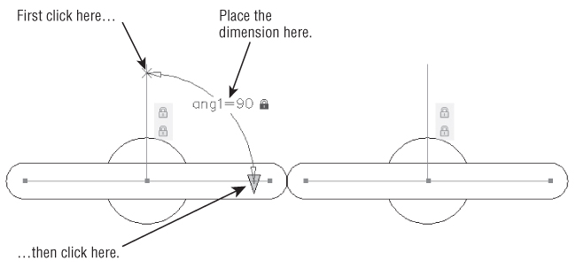
FIGURE 17.30 Adding the angular constraint to the
gatesample.dwgdrawing - Next, click the left horizontal line toward the right end of the line, as shown in Figure 17.30.
- Place the dimension as shown in Figure 17.30.
- The dimension text is highlighted. You want to keep the current value, so press ↵ to accept the default.
You have the first angular dimensional constraint in place. Next add a second one to the gate on the right, but this time you'll use the name of the first angular constraint as the dimension for the second one:
 In the Dimensional panel, click the Angular tool.
- Click the right vertical line near its top, as shown in Figure 17.31.
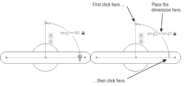
FIGURE 17.31 Adding the angular constraint to the second gate
- Click the right horizontal line near its right end (see Figure 17.31).
- Place the dimension as shown in Figure 17.31.
- At the highlighted text, type ang1↵. This will cause this constraint to follow the first one that you added.
Now you're ready to save the block and try it out:
- Click Close Block Editor on the Block Editor tab's Close panel, and save the block.
- Click the block to expose its grips.
- Click the arrow grip on the horizontal line.
- Type 45↵. Both sides of the block rotate about their own centers to a 45‐degree angle (see Figure 17.32).
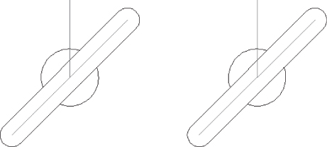
FIGURE 17.32 The two parts rotate in unison
- Click the arrow grip again, and type 90↵ to set the gate back to its original position.
You've got the basic function of the gate working, but you don't want the red lines to appear in the drawing since they are there to facilitate the action of the gate and are not really part of the drawing. Do the following to hide the red lines:
- Double‐click the Gate block to open the Edit Block Definition dialog box, and then click OK. The Gate block opens for editing.
 Click the Construction Geometry tool in the Manage panel.
- Select the four red lines and press ↵↵. Notice that the lines change from solid to dashed, indicating that they are now construction geometry.
- Click the Close Block Editor tool, and save the block. The block now appears without the red lines. If you click the block, the rotation grip still appears, and you can alter the block as before.
Now suppose that you want to have the gates rotate in opposite directions instead of in the same direction. You can add a user‐defined formula to modify the behavior of the angular constraints:
- Double‐click the Gate block to open the Edit Block Definition dialog box, and then click OK. The Gate block opens for editing.
 Click the Parameters Manager tool to open the Parameters Manager palette. You may recall that in Chapter 16, you used this palette to control the size of a concentric circle.
- Double‐click in the Expression column of the ang2 option, and type ang1 * ‐1↵.
- Close the Parameters Manager palette, and then save and close the block.
- Click the gate to select it, and then click the arrow grip.
- Type 22↵. Now the two parts rotate in opposite directions (see Figure 17.33).
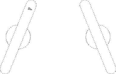
FIGURE 17.33 The gates moving in opposite directions
- Press Esc to clear the selection, and then save and close the file.
You can go on to add a block table using the Block Table tool to create a predefined set of angles, just as you did for the Door block earlier in this chapter. You can also add incremental values by using the Properties palette to change the angle constraint in a way similar to how you changed constraints in the sink exercise in the first part of this chapter.
Next let's take a look at a way to array objects automatically with dynamic blocks.
Filling in a Space Automatically with Objects
Perhaps one of the more tedious tasks that you'll face is drawing the vertical bars of a hand railing for an elevation view. You can draw a single bar and then use the Array command to repeat the bar as many times as needed, but when you have to edit the railing, you may find that you're spending more time adding and erasing bars.
In the next example, you'll see how you can create a block that automatically fills in vertical bars as the width of the railing changes. You'll start with an existing drawing of a single vertical bar and an outline of the railing opening around the bar:
- Open the
railsample.dwgfile. - Double‐click the object in the drawing to open the Edit Block Definition dialog box, and then click OK. This opens the Railvertical block for editing.
When the Block Editor opens, notice that the block already has a Linear parameter and a Stretch action added. Recall from the sink example at the beginning of this chapter that the Linear parameter and Stretch action let you vary the width of an object. In this case, the outermost rectangle is being stretched.
 On the Actions tab of the Block Authoring palettes, click the Array action.
- At the
Select parameter:prompt, click the blue Linear parameter (labeled as Distance), as shown in Figure 17.34.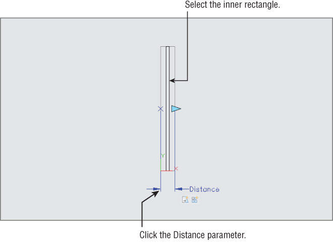
FIGURE 17.34 Adding the Array action to the Railvertical block
- At the
Select objects:prompt, select the dark vertical rectangle representing the vertical bar of the railing, as shown in Figure 17.34, and then press ↵. - At the
Enter the distance between columns (|||):prompt, enter 4↵. - Click Close Block Editor on the Block Editor tab's Close panel and save the changes.
- Click the block to expose its grips.
- Click and drag the blue arrow grip to the right. As the rail expands, additional vertical bars are added at 4″ intervals (see Figure 17.35).
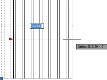
FIGURE 17.35 The Railvertical block adds vertical bars as its width expands
- Exit and save the file.
You can now use this block wherever you need to draw a simple railing with vertical bars. Another example of how the Array action might be used is in a side view of a bolt. You could show the threads of the bolt and use the Array action to increase the number of threads as the bolt is lengthened.
Including Block Information with Data Extraction
In Chapter 12, “Using Attributes,” you learned how you could attach data to blocks through attributes and then extract that data to spreadsheets or AutoCAD tables. You can also include dynamic block information that has been included in a property lookup table. This can be extremely useful for generating data for a bill of materials or in other situations if you need to track the numbers and types of items in your drawing.
To see how this works, you'll return to a version of the Door block that has some additions. This enhanced version of the Door block includes a left‐ and right‐hand version of the door that is controlled with the Visibility parameter. Figure 17.36 shows the door inserted into a drawing using different door sizes and left and right variations.
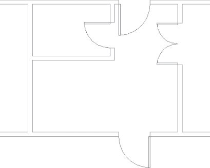
FIGURE 17.36 The door block inserted several times into a drawing with various widths and handedness
You'll use the Attribute Extraction command to see how the dynamic block data appears as an exported table or a spreadsheet:
- Open the
17‐extractsample.dwgfile. This file contains a dynamic door block that is similar to the one that you created earlier with the addition of a left and a right Visibility parameter. 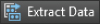 From the Annotate tab's Tables panel, click the Extract Data tool to start the Data Extraction Wizard.
- On the Begin screen, click Next.
- In the Save Data Extraction As dialog box, enter Test for the name and click Save. Note that the
Testfile will be saved in theMy Documentsfolder. If you want to place it somewhere else, make sure that you browse to the location that you prefer. - On the Define Data Source screen, click Next.
- On the Select Objects screen, remove the check mark from the Display All Object Types option so that only the Door block appears in the list and then click Next.
- On the Select Properties screen, remove the check mark from all but the Dynamic Block option in the right column, and make sure the Hand and Width options in the left column are the only ones selected (see Figure 17.37).
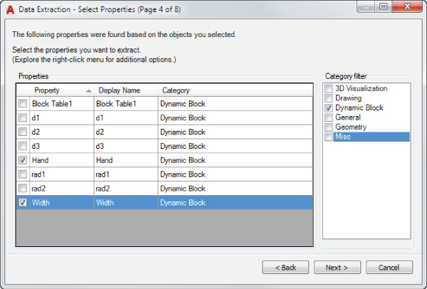
FIGURE 17.37 Set up the Select Properties screen to look like this
- Click Next. On the Refine Data page, you see the data that will be exported to a spreadsheet file or a table (see Figure 17.38).
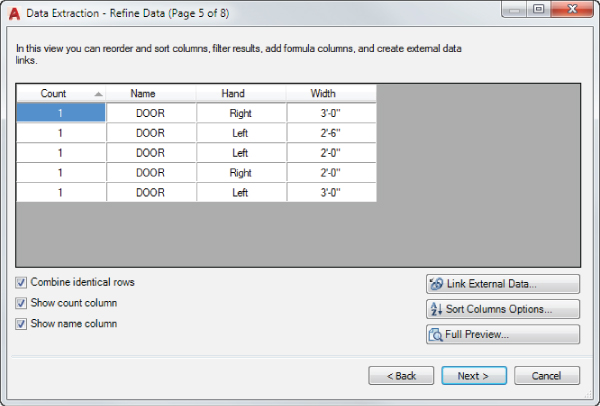
FIGURE 17.38 The resulting table to be extracted, as shown on the Refine Data screen of the Data Extraction Wizard
- You don't really want to extract this data, so once you've taken a good look at this screen, click Cancel and then Yes in the Quit Wizard dialog box.
This is the end of the door example, so you can exit this file. Save it for future reference if you like.
As you can see in Figure 17.38, a list is generated that shows each door in the drawing with its size and handedness. You could use this data as part of a door schedule.
The Bottom Line
- Work with the Block Editor. To create dynamic blocks, you need to become familiar with the Block Editor. You can use the Block Editor to modify existing blocks in your drawing.
- Master It What does the Edit Block Definition dialog box allow you to do?
- Create a dynamic block. A dynamic block is one to which you add grips so that you can modify the block in a number of ways.
- Master It Name some of the features of the Block Editor that let you add additional grip‐editing functions to a block.
- Add Scale and Stretch actions to a parameter. You can set up a dynamic block to perform multiple operations with a single grip.
- Master It What do you need to do to have one grip perform two functions?
- Add more than one parameter for multiple grip functions. In addition to having one grip perform multiple operations, you can add as many grips as you need to make your block even more customizable.
- Master It What feature do you use to set up a list of options for a block?
- Create multiple shapes in one block. Many of the dynamic block functions let you adjust the shape of the original block. Another feature lets you choose completely different shapes for the block.
- Master It When a block uses the Visibility parameter to set up different shapes, how do you select a different block shape in the drawing?
- Rotate objects in unison. Blocks can be set up so that the action of one set of objects affects another set. This chapter gives the example of rotating objects in unison.
- Master It Name the dimensional constraint that was used in the object rotation example in this chapter.
- Fill in a space automatically with objects. A dynamic block can help you automate the addition of repetitive elements to your drawing.
- Master It What is the name of the action used to produce copies of a block object at regular intervals in both the x‐ and y‐axes when the block is stretched?