Chapter 1
Understanding Digital Electronics
IN THIS CHAPTER
![]() Looking at the difference between analog and digital circuits
Looking at the difference between analog and digital circuits
![]() Exploring binary codes
Exploring binary codes
![]() Learning about logical operators
Learning about logical operators
![]() Building some very simple logic circuits with switches and lamps
Building some very simple logic circuits with switches and lamps
Welcome to the world of digital electronics. Beginning with this chapter, you start to learn about the fundamental building-block circuits that you’ll ultimately use to create computers and other advanced electronic devices.
Digital electronics is a complex, almost-overwhelming topic, but the building blocks are actually quite simple. In this chapter, you learn some basic principles, such as how to tell the difference between analog and digital circuits, how the binary system works, and how basic logic operations work. In the remaining chapters in this part, you build on that knowledge as you explore the amazing world of digital electronics.
Hang on!
Distinguishing Analog and Digital Electronics
All electronics can be divided into two broad categories: analog and digital.
Analog refers to circuits in which quantities such as voltage or current vary at a continuous rate. When you turn the dial of a potentiometer, for example, you change the resistance by a continuously varying rate. The resistance of the potentiometer can be any value between the minimum and maximum allowed by the pot.
If you create a voltage divider by placing a fixed resistor in series with a potentiometer, the voltage at the point between the fixed resistor and the potentiometer increases or decreases smoothly as you turn the knob on the potentiometer.
In digital electronics, quantities are counted rather than measured. There’s an important distinction between counting and measuring. When you count something, you get an exact result. When you measure something, you get an approximate result.
Consider a cake recipe that calls for 2 cups of flour, 1 cup of milk, and 2 eggs. To get 2 cups of flour, you scoop some flour into a 1-cup measuring cup, pour the flour into the bowl, and then do it again. To get a cup of milk, you pour milk into a liquid measuring cup until the top of the milk lines up with the 1-cup line printed on the measuring cup and then pour the milk into the mixing bowl. To get 2 eggs, you count out 2 eggs, crack them open, and add them to the mixing bowl.
The measurements for flour and milk in this recipe are approximate. A teaspoon too much or too little won’t affect the outcome. But the eggs are precisely counted: exactly 2. Not 3, not 1, not 1½, but 2. You can’t have a teaspoon too many or too few eggs. There will be exactly 2 eggs, because you count them.
One of the most common examples of the difference between analog and digital devices is a clock. Figure 1-1 shows two clocks: one analog and the other digital. On the analog clock, the time is represented by hands that spin around a dial and point to a location on the dial that represents the approximate time. On a digital clock, a numeric display indicates the exact time.
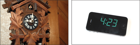
FIGURE 1-1: Analog and digital clocks.
Another example is a thermometer. A traditional glass–mercury thermometer has a small amount of liquid mercury inside a glass column. Mercury expands when it gets warm, so the warmer the mercury is, the higher it climbs in the glass column. Little tick marks are printed on the column to help you read the temperature. On a digital thermometer, the exact temperature is indicated by a numeric display.
So which is more accurate — analog or digital? In one sense, digital circuits are more accurate because they count with complete precision. You can precisely count the number of jelly beans in a jar, for example. But if you weigh the jar by putting it on an analog scale, your reading may be a bit imprecise because you can’t always judge the exact position of the needle. Say that the needle on the scale is about halfway between 4 pounds and 5 pounds. Does the jar weigh 4.5 pounds or 4.6 pounds? You can’t tell for sure, so you settle for approximately 4.5 pounds.
On the other hand, digital circuits are inherently limited in their precision because they must count in fixed units. Most digital thermometers, for example, have only one digit to the right of the decimal point. Thus, they can indicate a temperature of 98.6 or 98.7 but can’t indicate 98.65.
Here are a few other thoughts to ponder concerning the differences between digital and analog systems:
- The term digital is actually a reference to your digits — that is, your fingers. The most natural way for us humans to count is with our fingers.
- The term analog is a variation on the word angler — a reference to the ancient practice of estimating the size of a fish by spreading out your arms while saying, “He was at least this big!” That’s the original analog measurement.
- Saying that a system is digital isn’t the same as saying that it’s binary. Binary is a particular type of digital system in which the counting is all done with the binary number system. Nearly all digital systems are also binary systems, but the two words aren’t interchangeable. (For more information about the binary number system, see the next section, “Understanding Binary.”)
- Many systems are a combination of binary and analog systems. In a system that combines binary and analog values, special circuitry is required to convert from analog to digital, or vice versa. An input voltage (analog) might be converted to a sequence of pulses, one for each volt; then the pulses can be counted to determine the voltage.
- I made up that item about the angler, of course. Made you think about it for a second, though, didn’t I?
Understanding Binary
Most digital electronic circuits work with the binary number system. Thus, before you can understand the details of how digital circuits work, you need to understand how the binary numbering system works.
Knowing your number systems
A number system is simply a way of representing numeric values. Number systems use symbols called numerals to represent numeric quantities. The numerals 1, 2, and 3 represent the numeric quantities commonly known as one, two, and three.
In most number systems, numerals can be strung together to create larger numeric values, and the position of each numeral in the string determines its relative value. In the number 12, the numeral 1 represents the quantity ten, and the numeral 2 represents the quantity two. In the number 238, the numeral 2 represents the quantity two hundred, the numeral 3 represents the quantity thirty, and the numeral 8 represents the quantity eight.
You learned all this stuff in elementary school, so it’s completely intuitive. Unfortunately, it’s so intuitive that it’s easy to miss its brilliance — and to overlook the fact that it’s completely arbitrary.
The fact that we have ten numerals in our everyday counting system — which is called the decimal system, or base 10 — is a simple result of the fact that humans have ten fingers. If humans had evolved with 12 fingers, we would’ve learned how to count in base 12, and we would’ve invented two more numerals.
Different number bases may seem strange, but we actually encounter them every day without thinking about it. One common example is the system we use for keeping time. Our system for measuring time actually works in several number bases. An hour contains 60 minutes, for example. We recognize that 1:30 is halfway between 1:00 and 2:00 without even thinking about it. You may not realize it, but you’re thinking in base 60 when you tell time.
Counting by ones
Binary is one of the simplest of all number systems because it has only two numerals: 0 and 1. In the decimal system (with which most people are accustomed), you use 10 numerals: 0 through 9. In an ordinary decimal number, such as 3,482, the rightmost digit represents ones; the next digit to the left, tens; the next, hundreds; the next, thousands; and so on. These digits represent powers of ten: first 100 (which is 1); next, 101 (10); then 102 (100); then 103 (1,000); and so on.
In binary, you have only two numerals rather than ten, which is why binary numbers look somewhat monotonous, as in 110011, 101111, and 100001.
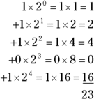
The positions in a binary number (called bits rather than digits) represent powers of two rather than powers of ten: 1, 2, 4, 8, 16, 32, and so on. To figure the decimal value of a binary number, you multiply each bit by its corresponding power of two and then add the results. The decimal value of binary 10111, for example, is calculated as follows:
Fortunately, converting a number between binary and decimal is something that a computer is good at — so good, in fact, that you’re unlikely ever to need to do any conversions yourself. The point of learning binary is not to be able to look at a number such as 1110110110110 and say instantly, “Ah! Decimal 7,606!” (If you could do that, Barbara Walters would probably interview you, and Hollywood would even make a movie about you. You’d probably be played by Dustin Hoffman.)
Instead, the point is to have a basic understanding of how computers store information and — most importantly — of how the binary counting system works, which I describe in the following section.
If you do find that you need to convert binary numbers to decimal, or vice versa, and you have access to a computer, you can use the Calculator program that comes free with Windows to do the conversion for you. For more information, see the nearby sidebar “Using Windows Calculator for binary conversions.”
Here are some of the most interesting characteristics of binary, which explain how the system is similar to and different from the decimal system:
In decimal, the number of decimal places allotted for a number determines how large the number can be. If you allot six digits, for example, the largest number possible is 999,999. Because 0 is itself a number, however, a 6-digit number can have any of 1 million different values.
Similarly, the number of bits allotted for a binary number determines how large that number can be. If you allot 8 bits, the largest value that number can store is 11111111, which happens to be 255 in decimal. Thus, a binary number that is 8 bits long can have any of 256 different values (including 0).
 To quickly figure how many different values you can store in a binary number of a given length, use the number of bits as an exponent of two. An 8-bit binary number, for example, can hold 28 values. Because 28 is 256, an 8-bit number can have any of 256 different values. This is why a byte — 8 bits — can have 256 different values.
 This “powers of two” thing is why digital systems don’t use nice, even round numbers for measuring such values as memory capacity. A value of 1k, for example, isn’t an even 1,000 bytes: It’s actually 1,024 bytes, because 1,024 is 210. Similarly, 1MB isn’t an even 1,000,000 bytes, but 1,048,576 bytes, which happens to be 220.
 One basic test of digital geekdom is knowing your powers of two because they play such an important role in binary numbers. Just for the fun of it, but not because you really need to know, Table 1-1 lists the powers of 2 up to 32.
Table 1-1 also shows the common shorthand notation for various powers of 2. The abbreviation k represents 210 (1,024). The M in MB stands for 220, or 1,024k, and the G in GB represents 230, which is 1,024MB.
TABLE 1-1 Powers of 2
Power | Bytes | Kilobytes | Power | Bytes | k, MB, or GB |
|---|---|---|---|---|---|
21 | 2 | 217 | 131,072 | 128k | |
22 | 4 | 218 | 262,144 | 256k | |
23 | 8 | 219 | 524,288 | 512k | |
24 | 16 | 220 | 1,048,576 | 1MB | |
25 | 32 | 221 | 2,097,152 | 2MB | |
26 | 64 | 222 | 4,194,304 | 4MB | |
27 | 128 | 223 | 8,388,608 | 8MB | |
28 | 256 | 224 | 16,777,216 | 16MB | |
29 | 512 | 225 | 33,554,432 | 32MB | |
210 | 1,024 | 1k | 226 | 67,108,864 | 64MB |
211 | 2,048 | 2k | 227 | 134,217,728 | 128MB |
212 | 4,096 | 4k | 228 | 268,435,456 | 256MB |
213 | 8,192 | 8k | 229 | 536,870,912 | 512MB |
214 | 16,384 | 16k | 230 | 1,073,741,824 | 1GB |
215 | 32,768 | 32k | 231 | 2,147,483,648 | 2GB |
216 | 65,536 | 64k | 232 | 4,294,967,296 | 4GB |
Doing the logic thing
One of the great things about binary is that it’s very efficient at handling special operations called logical operations. Logical operations compare two binary bits and render a third binary bit as a result. There are 16 possible logical operations. For now, I want to introduce you to three of them: AND, OR, and XOR.
The following list summarizes these three basic logical operations:
- AND: An AND operation compares two binary values. If both values are 1, the result of the AND operation is 1. If one value is 0 or both of the values are 0, the result is 0.
- OR: An OR operation compares two binary values. If at least one of the values is 1, the result of the OR operation is 1. If both values are 0, the result is 0.
- XOR: An XOR operation compares two binary values. If exactly one of them is 1, the result is 1. If both values are 0 or if both values are 1, the result is 0.
Table 1-2 summarizes how AND, OR, and XOR work.
TABLE 1-2 Logical Operations for Binary Values
First Value | Second Value | AND | OR | XOR |
|---|---|---|---|---|
0 | 0 | 0 | 0 | 0 |
0 | 1 | 0 | 1 | 1 |
1 | 0 | 0 | 1 | 1 |
1 | 1 | 1 | 1 | 0 |
You can apply logical operations to binary numbers that have more than one binary digit by applying the operation one bit at a time. The easiest way to do this manually is to line the two binary numbers on top of one another and then write the result of the operation below each binary digit. The following example shows how you calculate 10010100 AND 11011101:
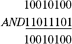
As you can see, the result is 10010100.
Using Switches to Build Gates
To give you an idea of how basic gates work, Projects 28, 29, and 30 show you how to assemble an AND gate, an OR gate, and an XOR gate using simple DPDT knife switches. In actual practice, gate circuits are built with transistors or with integrated circuits. But these three projects will give you a good idea of how gates work.
Figure 1-2 shows these three projects fully assembled. The AND gate (Project 28) is shown in the top photo. As you can see, the AND gate is implemented by connecting two switches together in series. Both switches must be closed for the lamp to light.
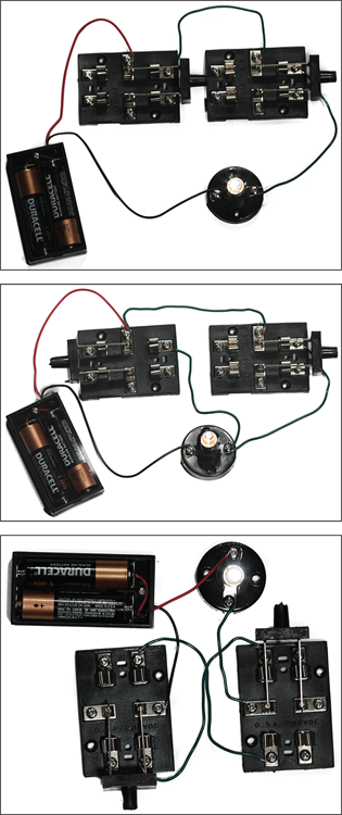
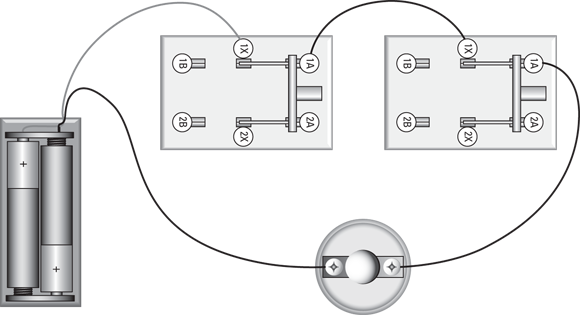
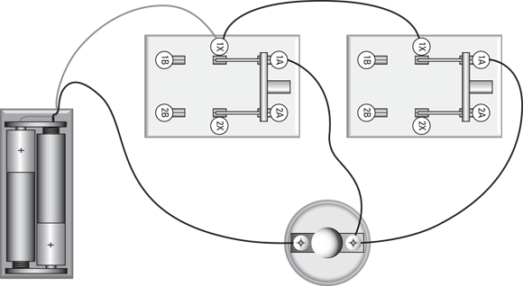
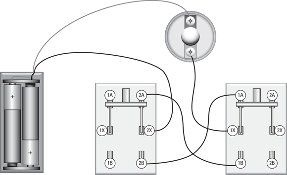
FIGURE 1-2: Implementing AND (top), OR (middle), and XOR (bottom) gates with knife switches.
The circuit for the OR gate (Project 29) is shown in the middle photo of Figure 1-2. To implement an OR gate with switches, you simply wire the switches in parallel. Then, the lamp lights if either of the switches is closed.
The XOR gate circuit (Project 30) is shown in the bottom photo of Figure 1-2. This wiring is a bit trickier. The DPDT switches are cross-connected in such a way that the circuit to the lamp is completed if one of the switches is in the A position and the other is in the B position, or vice versa. If both switches are in the same position, the circuit is not completed so the lamp does not light.
Project 28: A Simple AND Circuit
In this project, you use two switches and a lamp to create a simple circuit that performs a logical AND operation.
The two switches represent the two binary values that are input to the AND operation. A closed switch represents the binary value 1, and an open switch represents the binary value 0.
The lamp represents the binary output of the AND operation. When lit, the lamp represents the binary value 1. When not lit, the lamp represents the binary value 0.

Parts
- Two AA batteries
- One battery holder
- One lamp holder
- One 2.33 V flashlight lamp
- Two DPDT knife switches
- Two 5-inch lengths of 22-gauge stranded wire, stripped ½ inch on each end
Steps
Open both switches.
Move the handles to the upright position so that none of the contacts is connected.
- Attach the red lead from the battery holder to terminal 1X of one of the switches.
- Attach the black lead to one of the terminals on the lamp holder.
- Connect the two 5-inch wires as follows:
Connect From
Connect To
Terminal 1A of the first switch
Terminal 1X of the second switch
Terminal 1A of the second switch
The unused terminal of the lamp holder
- Insert the batteries into the holder.
Manipulate the switches to verify the correct operation of the AND circuit.
The switches should operate as follows:
Switch 1
Switch 2
Lamp
Open
Open
Off
Open
Closed
Off
Closed
Open
Off
Closed
Closed
On
Notice that the lamp comes on only when both switches are closed, which is exactly how an AND circuit should work.
You’re done! Give yourself a pat on the back, because you’ve just built your first logic circuit.
Project 29: A Simple OR Circuit
In this project, you build a simple OR circuit by wiring two switches in parallel to control a lamp. The lamp will be lit when either one of the two switches is closed. The switches represent the two binary inputs to the OR operation, and the lamp represents the binary output.

Parts
- Two AA batteries
- One battery holder
- One lamp holder
- One 2.33 V flashlight lamp
- Two DPDT knife switches
- Three 5-inch lengths of 22-gauge stranded wire
Steps
Open both switches.
Move the handles to the upright position so that none of the contacts is connected.
- Attach the red lead from the battery holder to terminal 1X of the first switch.
- Attach the black lead from the battery holder to the first terminal on the lamp holder.
- Connect the first 5-inch wire from terminal 1X of the first switch to terminal 1X of the second switch.
- Connect the second 5-inch wire from terminal 1A of the first switch to the second terminal on the lamp holder.
- Connect the third 5-inch wire from terminal 1A of the second switch to the second terminal on the lamp holder.
- Insert the batteries into the holder.
Manipulate the switches to verify the correct operation of the OR circuit.
The switches should operate as follows:
Switch 1
Switch 2
Lamp
Open
Open
Off
Closed
Closed
On
Closed
Open
On
Closed
Closed
On
Notice that the lamp is on whenever at least one of the two switches is closed. The lamp is off only when both switches are open. That’s the way an OR circuit should operate.
You’re done! Congratulate yourself on a job well done. You’ve completed your second logic circuit.
Project 30: A Simple XOR Circuit
In this project, you build a simple XOR circuit by wiring two switches to control a lamp. In this circuit, a lamp will light when one or the other switch is closed. If both switches are open or both are closed, the lamp won’t light. The switches represent the two binary inputs to the XOR operation, and the lamp represents the binary output.
Unlike the other two projects in this chapter, the switches in this project use both the A and B positions. Thus, a switch represents a binary 1 when it’s in the A position. In the B position, the switch represents a binary 0.
Notice how in the schematic diagram the A and B terminals are cross-connected between the two switches. That way, the circuit to the lamp will be closed only if the switches are in opposite positions. In other words, the lamp will light if SW1 is in the A position and SW2 is in the B position, or if SW1 is in the B position and SW2 is in the A position. If both switches are in the A position or if both switches are in the B position, the lamp won’t light.

Parts
- Two AA batteries
- One battery holder
- One lamp holder
- One 2.33 V flashlight lamp
- Two DPDT knife switches
- Three 5-inch lengths of 22-gauge stranded wire
Steps
Open both switches.
Move the handles to the upright position so that none of the contacts is connected.
- Attach the black lead from the battery holder to terminal 2X of the first switch.
- Attach the red lead to the first terminal on the lamp holder.
- Connect the first 5-inch wire from the second terminal on the lamp holder to terminal 1X on the second switch.
- Connect the second 5-inch wire from terminal 2A on the first switch to terminal 1B on the second switch.
- Connect the third 5-inch wire from terminal 2B on the first switch to terminal 1A on the second switch.
- Insert the batteries into the holder.
Manipulate the switches to verify the correct operation of the XOR circuit.
The switches should operate as follows:
Switch 1
Switch 2
Lamp
Open
Open
Off
Open
Closed
On
Closed
Open
On
Closed
Closed
Off
You’re done! Congratulate yourself on a job well done. You’ve completed your third logic circuit!