In this chapter, you are going to look at creating a square wave on one of the CCP outputs.
After reading this chapter, you should understand what the CCP module is. You should also appreciate why you would want to create a square wave output and how to use the PWM aspect of the CCP module to create a square wave.
In Chapter 6, you will look at an alternative approach to creating a square wave. The approach will involve using the compare aspect of the CCP module and using interrupts.
Why Create a Square Wave?
To answer this question, you are going to look at the two uses of a square wave. The first is in producing musical notes and the second is in setting the speed of a DC motor.
Musical Notes
The Frequency of the More Common Musical Notes
Note | Frequency (Hz) | Wavelength (cm) |
|---|---|---|
G3 | 196.00 | 176.02 |
G#3/Ab3 | 207.65 | 166.14 |
A3 | 220.00 | 156.82 |
A#3/Bb3 | 233.08 | 148.02 |
B3 | 246.94 | 139.71 |
C4 | 261.63 | 131.87 |
C#4/Db4 | 277.18 | 124.47 |
D4 | 293.66 | 117.48 |
D#4/Eb4 | 311.13 | 110.89 |
E4 | 329.63 | 104.66 |
F4 | 349.23 | 98.79 |
F#4/Gb4 | 369.99 | 93.24 |
G4 | 392.00 | 88.01 |
C4 is the note that is more commonly known as middle C.

The term wavelength relates to the distance the sound travels to complete one full cycle of the signal or sound.

The answers to the exercises are at the end of the chapter. In this exercise, you should calculate the wavelength of the following frequencies, knowing that the velocity at which they travel is the velocity of sound:
Frequency = 48.999Hz
Frequency = 1046.502Hz
Frequency = 2,200Hz
If you could produce a signal at any of the frequencies in Table 4-1, then you could produce the respective musical note. The signal does not have to be a perfect sinusoidal waveform, but it would be better if it was.
In this way then, if you could get the PIC to produce a square wave at the correct frequencies, you could produce a series of musical notes. This is what you will do in the next chapter: you will produce a simple musical keyboard with eight notes.
The Speed of the Simple DC Motor
With respect to the control of a DC motor we are talking about setting the speed of the motor. This does not mean you will be controlling the speed because the load varies. You will simply be setting the speed of the motor. Controlling the speed (i.e. ensuring the speed stays the same irrespective of the load applied to the motor) is a whole different ballgame. Speed control is a book by itself.
The speed of the motor depends upon the voltage that is applied to that motor. Therefore, if you can vary the voltage applied to the motor, you can vary the speed of the motor.
Pulse Width Modulation
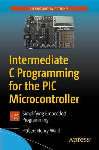
A typical square wave
The wave form, shown in Figure 4-1, is DC as the voltage never changes polarity. In this case, it is always positive. The wave form has what is termed a 50/50 duty cycle since the up time, or on time, named “mark” time, is the same as the down time, or off time, named “space” time. The mark time (M), or up time, is the pulse that is referred to in PWM. The width is the length of time that the mark, or pulse, extends for. The modulation in PWM refers to the fact that you vary the length of time that the mark extends for (i.e. PWM). Note that since the total time (i.e. the mark time plus the space time, known as the periodic time, T) does not vary, then as you increase the mark time you must decrease the space time and visa-versa.

Note that Vavge is the average voltage, Vm is the voltage maximum, M is the mark time, T is the periodic time for the wave form (i.e. the time to complete one full cycle), and S is the space time.
Note that  is termed the duty cycle. When the M time is equal to the space time, then the duty cycle is termed 50/50 and the average voltage is
  .
.
I hope the above paragraphs explain the importance of creating a square.
Creating a Square Wave with the PWM Mode
One way you can create a square wave is to use the PWM mode of the CCP module of the PIC. This is the Capture Compare and Pulse Width Modulation module of the PIC. This module is a mixture of hardware, in that the actual circuitry is inside the PIC, and firmware, preprogrammed operations that are in the PIC. In this chapter, you will look at using the CCP in PWM mode to create the square wave.
What the programmer has to do is create the timing for the period T and the mark time, M. This is done using the timer2 inside the PIC, which just counts clock pulses. The procedure for doing this is as follows.
The Bits of the CCPXCON Register
Bit7 | Bit6 | Bit5 | Bit4 | Bit3 | Bit2 | Bit1 | Bit0 |
|---|---|---|---|---|---|---|---|
- | - | DCxB1 | DCxB0 | CCPxM3 | CCPxM2 | CCPxM1 | CCPxM0 |
Bits 7 and 6 | These are not used and should be read as 0. | ||||||
Bits 5 and 4 | These are used to store the two LSBs of the 10-bit number for the duty cycle. | ||||||
Bits 3, 2, 1, and 0 | These are used to set the use of the CCP module according to the setting shown in Table 4-3. | ||||||
The Four Bits That Configure the CCP Modules
Bit3 | Bit2 | Bit1 | Bit0 | Setting |
|---|---|---|---|---|
0 | 0 | 0 | 0 | Capture/Compare/PWM disabled |
0 | 0 | 0 | 1 | Reserved |
0 | 0 | 1 | 0 | Compare mode, toggle output on match |
0 | 0 | 1 | 1 | Reserved |
0 | 1 | 0 | 0 | Capture mode every falling edge |
0 | 1 | 0 | 1 | Capture mode every rising edge |
0 | 1 | 1 | 0 | Capture mode every fourth rising edge |
0 | 1 | 1 | 1 | Capture mode every sixteenth rising edge |
1 | 0 | 0 | 0 | Compare mode, initialize CCPx pin low |
1 | 0 | 0 | 1 | Compare mode, initialize CCPx pin high |
1 | 0 | 1 | 0 | Compare mode, generate software interrupt |
1 | 0 | 1 | 1 | Compare mode, trigger special event |
1 | 1 | 0 | 0 | PWM mode P1A, P1C active high P1B P1D active high |
1 | 1 | 0 | 1 | PWM mode P1A, P1C active high P1B P1D active low |
1 | 1 | 1 | 0 | PWM mode P1A, P1C active low P1B P1D active high |
1 | 1 | 1 | 1 | PWM mode P1A, P1C active low P1B P1D active low |
It should be noted that the last four settings in Table 4-3 show the mode for the PWM when the PIC is used in the extended mode. In this mode, the programmer has the ability to produce a H drive output. However, if all you want is a simple square wave output, then these four bits can be set to 1100, b3 and b2 can be a logic 1, and b1 and b0 can be set to a logic 0.
If you want to produce two square wave outputs, you must write to both CCP1CON and CCP2CON registers as well as load both CCPR1L and CCPR2L with the correct value. This will produce two square waves of the same frequency set by the value in the PR2 register. A program that produces two square waves is shown in Listing 4-2.
Bits 7 and 6 of the CCP1CON register are not used, so leave them at logic 0.
Bits 5 and 4 are where you store the two least significant bits of the binary number that is used to control the width of the mark pulse. You will look at this later in the chapter.
- It is the least significant four bits (b3, b2, b1, and b0 of both CCPXCON registers) that control what mode the CCP module is in. Since you are trying to create a square wave with PWM, you want to set this module to PWM mode. This is done by setting these four bits as follows:
b3 = 1
b2 = 1
b1 = x
- b0 = x
The x means it does not matter what logic level they are.
The data sheet does indicate that b1 and b0 can be set to any logic level; see section 15 in the datasheet. However, this is true only if you are dealing with just one CCP and creating one square wave output. The PIC18F4525 has two CCP modules, which means you can create two square wave outputs. When you do this, the phase relationship between the two square waves can be affected. This concept will be discussed later in this chapter.
One last thing before you start creating your square wave. You need to know on what pin the two square waves will be outputted by the PIC. The two outputs are CCP1 and CCP2. CCP1 is fixed on PORTC Bit2 (i.e. PORTCbits.RC2). However, CCP2 has two possible output locations. It can be sent out on PORTBbits.RB3 or PORTCbits.RC1. To decide which of these two bits the CCP2 is on, you must use one of the CONFIG words when you first set the CONFIG words up. The default setting is PORTCbits.RC1. I normally leave it at this so that I can use my configuration header file in all my projects.
The process of creating a square wave is based around letting timer2 count up until a time equal to the periodic time T of the desired square wave has been reached. Timer2, like all timers, simply counts clock pulses and so a count of one will equal a specific time according to the clock frequency used by timer2. Therefore, you need to know the number of pulses the timer has to count to reach the periodic time of the frequency of the square wave. This number is loaded into a special function register called PR2. When the value in timer2 matches the value in this PR2 register, then the square wave starts a new cycle.

Creating a 500Hz Square Wave
The best way to explain the process is to go through a simple example. In the following example, you will create a 500Hz square wave with an 8Mhz internal oscillator and a TMR2Preset value of 16. I will explain what the timer preset value does later.

This means that to get a square wave with a frequency of 500Hz using an 8MHz oscillator, you simply have to load the PR2 with the value of 249, which is 0b11111001 or 0XF9, and then set the mark-to-space ratio.
I feel I should point out that timer2 counts clock pulses and the clock runs at a quarter of the frequency of the oscillator; note that is why there is a number 4 in Equation 4-4. This means that, with an oscillator frequency of 8Mhz, the clock runs at a 2Mhz. However, you have the ability to slow timer2 even more by dividing this 2Mhz frequency further. To control how much more you divide this frequency by, and so slow it down, use the timer2 preset value. There are three possible values this preset can be set to: 1, 4, and 16. You are using the value 16 for this timer preset, hence the 16 in Equation 4-5. This means that timer2 is counting at a rate of 2Mhz divided by 16, so at a frequency of 125kHz. The periodic time for this frequency is  therefore = 8μs. This means it takes 8μs for timer2 to count one tick. This means that it will take 250x8μs for timer2 to count from 0 to 249. Therefore, it will take 2ms for the timer to count from 0 to 249, which is the periodic time for the 500Hz square wave you are trying to produce.
I hope this explains how Equation 4-4 works and how the PIC uses timer2 to create a square wave. As I stated earlier, you want to know the number the timer2 must count up to create a time equal to the periodic time of the frequency of the square wave you are creating.
The Mark Time or Duty Cycle
So far, you have loaded the PR2 register with the correct number to create a 500Hz square wave but there must be a mark time and a space time or a duty cycle. You can’t leave this calculation out because the registers involved will have data in them already but it will most likely be an unusable value. You need to make sure the value in the register used to control the mark-to-space ratio is the one you want.
You will start by creating a 50/50 duty cycle, which means the mark and space time are both equal to  .
.

This is taken from equation 15.2 in section 15.4 of the datasheet for the PIC18F4525.

So you have calculated two numbers that, when used properly, will give you a 500Hz square wave with a 50/50 duty cycle. There are two issues to consider when it comes to storing these numbers.
First, you set the TMR2 Preset value using the T2CON register. There are three possible values for the TMR2 preset: 1, 4, and 16. Why did I choose 16? Well, if I had chosen 4, the PR2 number would have worked out at 996, and if I had chosen 1, the PR2 number would be 3984. So what is wrong with that? The answer is that this PIC is an 8-bit PIC and unless you can change them, as you can with some SFRs, all registers are 8 bits and an 8-bit register can only hold a value up to 255. So that is why a preset value of 16 was chosen: to reduce the value to below 255. You have the other possible values for the TIMER 2 Preset because you may want different frequencies for the square wave, and you could use different oscillator settings.
Now, as the registers are only 8 bits long, how can you store the number for the duty cycle since the value of 500 uses nine binary numbers? Microchip have given us a solution for this problem similar to the way you store the 10-bit results of the ADC conversion**. You can store the most significant 8 bits in a special register called CCPRXL. Note that there are two, one for each CCP module, so the X will be either 1 or 2.
The two least significant bits go into b5 and b4 of the CCPXCON registers; again, X is 1 or 2. The number you calculated using Equation 4-7 was 500 or 0b111110100. This means b5 and b4 of the CCPXCON registers are set to logic 0 and the 0b01111101 (note that the extra 0 at Bit7 is there to complete the 8-bit number) is loaded into the appropriate CCPRXL registers. You will use CCPR1L since you will be using the CCP1 output and thus the CCP1CON register to create the square wave.
** Please refer to my first book, C Programming for PIC Microcontrollers, for a complete explanation of the ADC.
This will then make a 500Hz square wave appear on the CCP1 of the PIC with a 50/50 duty cycle, assuming you have set the CCP1 pin to output.
The Program for the 500Hz Square Wave
Analysis of Listing 4-1
This instruction simply loads the control register T2CON with the following 8-bit number: 0b00000110.
The T2CON Register for Controlling Timer2
Bit7 | Bit6 | Bit5 | Bit4 | Bit3 | Bit2 | Bit1 | Bit0 |
|---|---|---|---|---|---|---|---|
- | T2OUTPS3 | T2OUTPS2 | T2OUTPS1 | T2OUPS0 | TMR2ON | T2CKPS1 | T2CKPS0 |
Bit7 | Not used | ||||||
Bit6 | These are used to enable Post scales for timer2 0000 = 1:1 0001 = 1:2 " " " 1111 = 1:16 | ||||||
Bit5 | |||||||
Bit4 | |||||||
Bit3 | |||||||
Bit2 | TIMR2ON | Logic 0 means off, Logic 1 means on | |||||
Bits 1 - 0 | TMR2 Preset | 00 = 1 | 01 = 4 | 1x = 16 | |||
The following is an explanation of what loading the T2CON register with 0b00000110 does.
This sets Bit2 to a logic 1, which simply turns the timer2 on.
This instruction also sets Bit1 to a logic 1 and Bit0 to a logic 0. This sets the timer2 preset to a value of 16.
Note also that Bits 6, 5, 4, and 3 are set to logic 0, which sets the Post Scalar to 0000. The use of the Post Scalar will be explained in Chapter 6.
Note that Bit7 is not used, so it is set to a logic 0.
This simply loads the CCP1CON, the control register for the CCP1 module with the value 0b00001100. A description of the usage of this control register is given in Tables 4-2 and 4-3. The particular use of the bits is given here.
Bit 7 and 6 of the CCP1CON register are not used, so leave them at logic 0.
Bits 5 and 4 are set to a logic 0 as this is what the two least significant bits of the binary conversion of 500 are as calculated using Equation 4-7.
The remaining fours bits (3, 2, 1, and 0) are set to 1100, respectively, to put the CCP module into the PWM mode of operation.
This loads the CCPR1L 8-bit register with the MSB bits of the 500 value created with Equation 4-7 (i.e. it loads 0b01111101 or 0X7D as shown).
This is using the while (test) type instruction. If the result of the test is true, the program must do what the instruction tells it to do. With the test being the simple (1), then the test result is always true since a logic 1 means true. This means that the micro must always do what the instruction tells it to do.
As there is nothing between the (1) and the semicolon, which signifies the end of the instruction, this while (1) test means the micro will do nothing forever. In this way, you are halting the micro at this point in the program.
This is all you need to do, so there will now be a 500Hz square wave outputted by the PIC on the CCP1 output. This is on bit2 of PORTC.
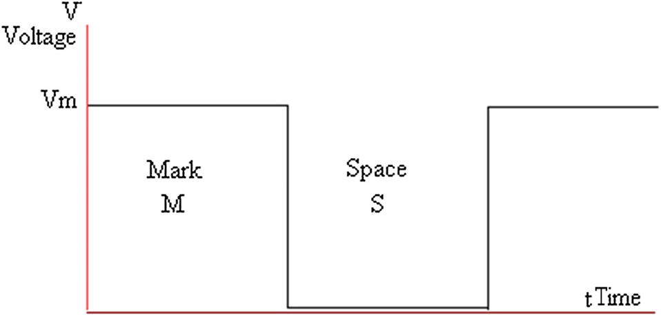
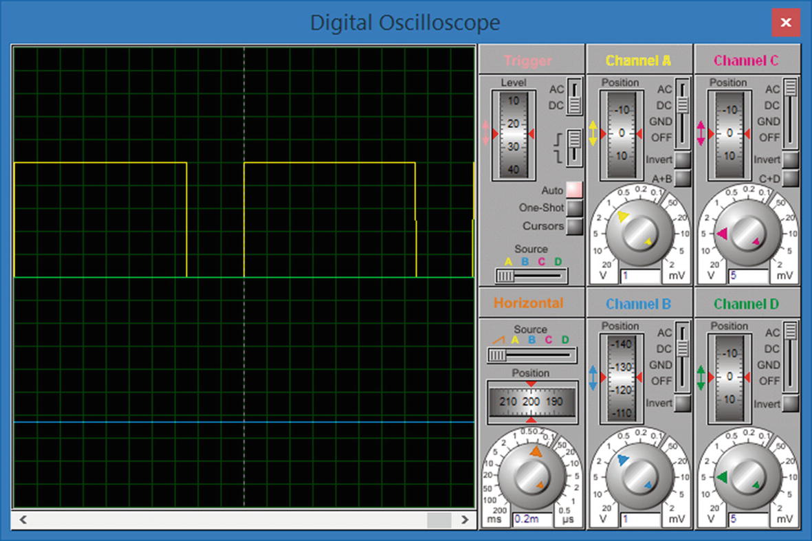
The simulation of the 500Hz square wave
The oscilloscope shows a square wave with mark and space time equal to each other. Also, as the time for each square division of the screen is 0.2ms and there are 10 squares in one complete cycle, the periodic time T for the waveform is 10 x 0.2m = 2ms. This is the correct periodic time for the 500Hz square wave.
Creating Two Square Wave Outputs
This section of the text will just look at creating two square waves. It will also look at controlling the phase relationship between the two square waves.
The Program for Two Square Wave Outputs
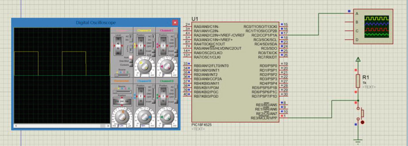
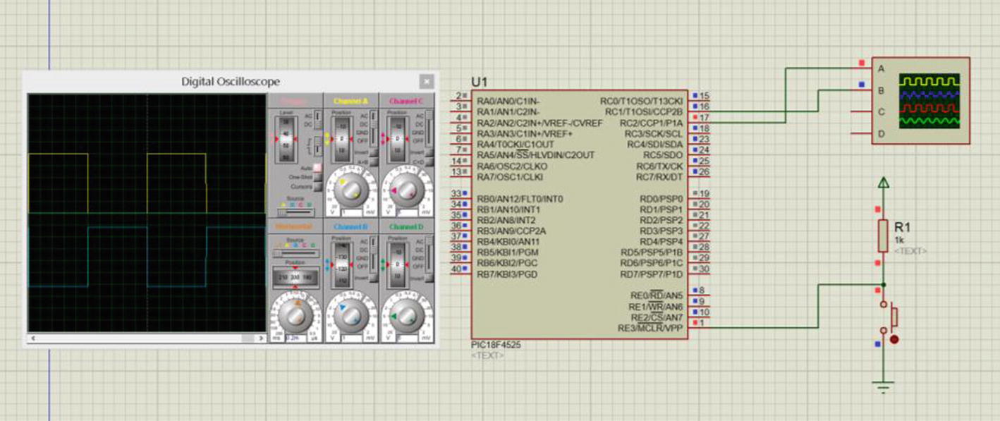
The circuit simulation
Channel A, the yellow waveform, displays the CCP1 output and channel B, the blue waveform, displays the CCP2 output. It’s quite clear they are both 50/50 duty cycle and they are at 500Hz.
One thing that I should point out is that they are in phase with each other. This is because I have set Bit1 and Bit0 of the CCP1CON register to logic 0.
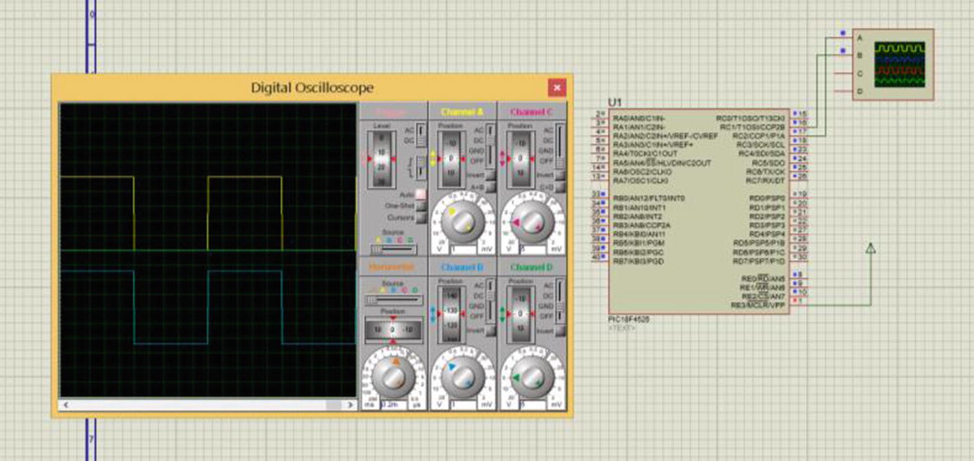
If you now set Bit1 and Bit0 of the CCP1CON register to logic 1, which is still allowed, the two square waves will be out of phase by 180O. Try it and see what happens.
Here b1 is set to logic 1 and b0 is set to logic 0.
The two wave forms are out of phase by 180O because when the channel A trace is positive, the channel B trace is at 0V. When the channel B trace is positive, the channel A trace is at 0V. This means the two wave forms are said to be in “anti-phase” with each other.
Setting the Speed of a DC Motor
Now that you have learned how to create one or two square wave outputs, let’s make use of them. Setting the speed of a DC motor is just one of the many useful applications of PIC programming and yet it is probably one of the easiest. Indeed, all you have to do is vary the duty cycle of the square wave since the DC motor will respond to the average voltage. For example, when the duty cycle is 50/50, then you should have half-speed. If it is 75/25, you have 3/4 speed, and when it is 25/75 you have 1/4 speed. However, you should bear in mind that this is with an ideal motor. All real motors have friction and inertia to deal with but the speed can, in essence, be set in this way.
Therefore, to vary the speed you need only change the number stored in the CCPRXL and the other two bits. Note that I am saying setting, not controlling, because if you want to control the speed of the motor you need to measure the actual speed and use it in some sort of closed loop control. This can be done using a PIC micro but this is more than I intend to do in this book.
To help explain setting the speed of the motor, let’s change the duty cycle of the CCP1 output in Listing 4-1 to 75/25 and see what happens to the voltage output on the oscilloscope.


This number converts to 0b1011101110, which means b5 in CCP1CON is set to logic 1 and b4 is set to logic 0. Then 0b10111011 or 0XBB is loaded into the CCPR1L.
The Changes to Produce a 75/25 Square Wave Output
The square wave output with 75% mark and 25% space
Determine the minimum value of the numbers to be stored in the PR2, CCP1CON, and CCPR1L registers if you want a 20/80 duty cycle with a 2kHz square wave, using the 8MHz internal oscillator.
Driving the Motor
You now have to think about how you can drive the DC motor. Unless you are using very small 5V DC motors, you cannot drive them directly from the PIC. Even with 5V motors, the current the motor could take would have to be fairly small, in the order of 100mA maximum. This is because most outputs of the PIC can only source, or sink, a small amount of current.
This being the case, you will most likely need to use a driver chip. There are many that are suitable, such as the ULN2004A and the ULN2803A. They are Darlington transistors arrays. The ULN2004A is a 16-pin device with seven Darlington transistors; the ULN2803A is an 18-pin device with eight Darlington transistors. Each of the Darlington transistors can sink up to 500mA. They can be connected in parallel if required to accommodate a device that sinks more current. They can be supplied by a VCC up to 30V.
If that current capability is not enough, you can use a single Darlington transistor, and the TIP122 is one such transistor. It can sink up to 5Amps of current.
The ULN Drivers and the TIP122 actually switch the ground onto the load, so they sink the current of the load through them. Since most loads are inductive, and the switching off of inductive loads can lead to high voltage spikes across the Darlington transistor, or other switching device, these drivers all have flywheel diodes to protect them. One final point to appreciate about these driver ICs is that they can be driven from TTL voltages.
All these parameters make them ideal for interfacing the PIC to real-word circuits.
Creating a Three-Speed DC Motor Program
If no button is pressed, the motor runs at half speed.
If the button connected to RA0 is pressed, the motor speed increases to 3/4 speed.
If the button connected to RA1 is pressed, the motor speed increases even further.
If the button connected to RA2 is pressed, the motor speed reduces to 1/4 speed.
If the button connected to RA3 is pressed, the motor speed returns to 1/2 speed.
The Three-Speed Control of a DC Motor
The test asks if the logic on Bit0 of PORTA is a logic 1. This will only come about if someone has pressed the switch connected to Bit0 of PORTA. If someone has pressed the switch, then the test will be true and the PIC will carry out the instruction CCPR1L = 0XBB;, which simply loads the CCPR1L with the value 0XBB. This is the value needed to increase the speed to 75%, as calculated in Equation 4-6.
Lines 14 and 15 change the speed of the motor in a similar way.
This program is not using the debounce subroutine that was used in Chapter 3. This because you are not concerned with how many times the switch is pressed. However, in a practical situation, it would be useful to use the debounce subroutine if only to prevent any stray noise on the switches changing the speed of the motor unintentionally.
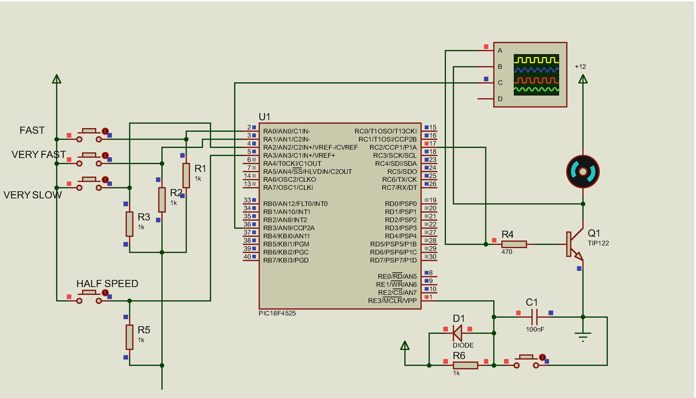
The schematic for the three-speed motor
Note that I am using the TIP122 Darlington transistor to switch the motor to ground and so sink the current from the motor. R4 is needed to prevent the transistor pulling the output of the PIC down to around 1.4V. It also sets the current being fed into the base of the TIP122.
The resistors R1, R2, R3, and R5 are there to limit the current flowing through the switches to around 5mA, thus protecting the switches. I refer to this arrangement for the switching as a pull up, as pressing the switch pulls the voltage at the input up to VCC. Others may refer to the arrangement as pull down resistors since the resistors are in the path down to 0V.
Using a Variable Input Voltage to Change the Speed of a DC Motor
This will involve using an analog input; you will use PORTA Bit0 and the ADC to convert the analog voltage to a binary value. Then you’ll use this value to vary the mark time of the square wave feeding the transistor that turns the motors on. This concept is shown in the circuit in Figure 4-7.
The algorithm: The PIC will constantly read the input voltage at the analog input on Bit0 of PORTA. You use that result of the ADC to vary the mark time of the square wave feeding the Darlington transistor.
The Variable Speed DC Motors
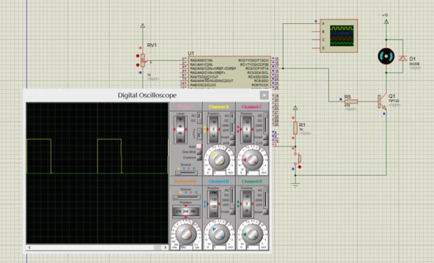
Setting the speed of a DC motor with a variable resistor
Analysis of Listing 4-5
This loads the CCPR1L with the 8-bit number stored in the ADRESH. Note that the ADRESH is where the PIC stores the high byte of the result of the ADC conversion. However, the 8-bit number is multiplied by 0.95 first before it is loaded into the CCPR1L register. However, multiplying an integer by 0.95 could result in a decimal value as the result. A decimal number cannot be loaded into the CCPR1L, so the value must be rounded up first before it is stored in the CCPR1L. This is why you need to use the round function that is listed in the maths.h header file included in line 4.
Another problem is that the value stored in the CCPR1L register cannot be allowed to produce a mark time that is equal to or greater than the period of the square wave. If this was allowed to happen, the square wave would collapse. Since the period time is set by the value in the PR2 register, which in this case is 249, the value for the mark time cannot be allowed to be the same or greater than the value in the PR2 register (i.e. it cannot be the same or greater than 249 in this case). Therefore, if you set the maximum value that can be loaded into the CCPR1L register at 242, a value that is less than 249, then you can determine the multiplying factor that you need to use here.

This line and the next two lines all write to registers that control the ADC module inside the PIC. For a thorough analysis of how this module works and how these registers allow you as a programmer, to control it, you should read my first book, C Programming for PIC Microcontrollers. However, I will briefly explain what these three instructions do.
This controls how long the PIC waits for the whole acquisition and conversion of the analog input to complete. If it does not wait long enough, the result may be inaccurate. If the PIC waits too long, it could be wasting time. Therefore, you must get this setting correct.
Table 4-2 describes what each of the 8 bits in this control register does. Loading 0X05 into the register actually loads 0b00000101 in binary into the register. From that, you can see that Bit2 is a logic 1, which simply turns timer2 on.
Also, Bit1 is a logic 0 and Bit0 is a logic 1. This sets the timer2 preset value to 4.
![$$ PERIOD=frac{left( PR2+1
ight)left[4 imes mathrm{Timer}2mathrm{PreSet}
ight]}{OSCFequency} $$](https://imgdetail.ebookreading.net/20201209/5/9781484260685/9781484260685__intermediate-c-programming__9781484260685__images__497005_1_En_4_Chapter__497005_1_En_4_Chapter_TeX_Equ11.png)


This is the only instruction inside the curly brackets. All it does is call the subroutine changeSpeed. In this subroutine, the micro reads the input on bit0 of PORTA. It then converts the value from analog to digital in the ADC module. It then loads the CCPR1L register with the modified result. Note that it is the CCPR1L register that alters the mark time of the square wave. Therefore, all the program does forever is alter the pulse width of the voltage applied to the motor and thus it alters the speed of the motor.
Note that since there is only one instruction inside the curly brackets, this instruction could have been written as
while (1) changeSpeed ();
This is the closing bracket for the main loop.
I hope this explains how the program uses the PWM to set the speed of a simple DC motor by using a variable input.
Creating a Musical Note
As stated earlier, all sounds have their own individual frequency, or combination of frequencies, that allows us humans to separate them from other sounds. Some sounds have a combination of frequencies but a pure note will have just one frequency. The note middle C has a frequency of 261.63Hz with a wavelength of 1.3187 m. See the table in Appendix 7. Ideally the signal should be a perfect sinusoidal waveform. However, a square at 261.63Hz will be good enough for most uses. If you want a more perfect wave, you can pass the square wave through a low-pass filter. However, a simple passive filter will attenuate the signal, therefore an active filter may be better. This is not covered in this book.
Creating the Middle C Note

![$$ mathrm{PERIOD}=left[ PR2+1
ight]left(frac{4 imes TMR2mathrm{Preset}}{mathrm{OSCFreq}}
ight) $$](https://imgdetail.ebookreading.net/20201209/5/9781484260685/9781484260685__intermediate-c-programming__9781484260685__images__497005_1_En_4_Chapter__497005_1_En_4_Chapter_TeX_Equ15.png)
![$$ herefore mathrm{OSCFreq}=left[ PR2+1
ight]left(frac{4 imes TMR2mathrm{Preset}}{mathrm{PERIOD}}
ight) $$](https://imgdetail.ebookreading.net/20201209/5/9781484260685/9781484260685__intermediate-c-programming__9781484260685__images__497005_1_En_4_Chapter__497005_1_En_4_Chapter_TeX_Equa.png)
![$$ mathrm{OSCFreq}=left[124+1
ight]left(frac{4 imes 16}{3.822{mathrm{E}}^{hbox{-} 3}}
ight)=2.093145 MHz $$](https://imgdetail.ebookreading.net/20201209/5/9781484260685/9781484260685__intermediate-c-programming__9781484260685__images__497005_1_En_4_Chapter__497005_1_En_4_Chapter_TeX_Equb.png)
The Three Possible Oscillator Frequencies to Produce the Note Middle C
TMR2Preset Value | Oscillator Frequency |
|---|---|
1 | 130.822kHz |
4 | 523.286kHz |
16 | 2.093145MHz |
Since you are using the internal oscillator block, then using the data sheet you can see that any of the available oscillator frequencies would give the same percentage error of around 4.4%. Therefore, it is up to you which oscillator frequency you should use. I chose the 2Mhz oscillator frequency that uses a TMR2Preset value of 16.


As the PR2 register can only store whole integers, let the PR2 value = 118.


The Code to Create the Note Middle C

The oscilloscope display of a simulation of the program
Figure 4-8 shows the display on the oscilloscope of a simulation of the program. You can see that the time to complete one cycle is 3.8ms, which is the correct periodic time for the note middle C.
It is not showing a perfect 50/50 duty cycle due to the rounding errors in the calculations. An alternative approach, which maybe a better approach, to producing this middle C note is covered in Chapter 7.
Creating a Musical Keyboard
- 1.
You need to save the settings for the CCP1CON register and the CCPR1L register for all of the musical notes you are going to make available.
- 2.
You also need to allocate an input to each of the eight notes you will be using.
The Code for the Musical Keyboard
The Analysis Of Listing 4-7
This includes a header file that defines phrases for the settings of the CCP1CON register and the CCPR1L register to create a range of different frequency square waves, one for each musical note you want to use. An example of one of the definitions is
#define C4 PR2 = 118, CCPR1L = 0X3B, CCP1CONbits.DC1B1 = 1, CCP1CONbits.DC1B0 = 1;
These are the values that have been calculated for the note C4, which is middle C. Note that I am also including setting the two bits in the CCP1CON register. They are
CCP1CONbits.DC1B1 = 1, CCP1CONbits.DC1B0 = 1;
Note that CCP1CONbits.DC1B1 is actually Bit5 of the CCP1CON register and CCP1CONbits.DC1B0 is Bit4.
There is a small difference between this type of definition and the previous definitions you have used:
#define startbutton PORTAbits.RA0
The above definition for the startbutton does not end with a semicolon. However, the #define for the note C4 above does end with a semicolon.
This is because the #define C4 is listing a series of instructions and each instruction is separated by a comma but the last one uses the semicolon because it is the end of the list of instructions. There are four instructions for each definition of the note.
The #define startbutton PORTAbits.RA0 is really explaining to the compiler what the label startbutton stands for.
The full listing for this musicalNotes.h header file is given in Appendix 7.
This overrides the setting the PICSetUp.h header file as you want to reduce the oscillator frequency to 2Mhz. This is needed because at 8Mhz the value calculated for the PR2 would be 472. This would be too big to go into an 8-bit register. You cannot divide the frequency any more so you need to reduce the frequency from 8Mhz to 2Mhz.
Lines 30 to 35 set out by asking if the switch connected to bit0 of PORTA has been pressed. If it has, the micro carries out the instructions to produce the note G3. It then calls the debounce subroutine and makes the micro wait until the switch has been released.
In this way, the PIC will play the note G3 for as long as the user keeps the button on Bit0 of PORTA pressed.
This makes the micro carry out the following series of instructions:
PR2 = 70, CCPR1L = 0X4F, CCP1CONbits.DC1B1 = 0, CCP1CONbits.DC1B0 = 1;
This is because the phrase Nonote is defined as that in the musicalnote.h header file.
What this does is make the mark time bigger than the period as set by the PR2 value. This will make the PIC send out a flat line on CCP1 instead of a square wave. Therefore, the frequency will be zero and no sound will be sent out.
The lines 36 to 149 simply ask if a button connected to one of the inputs has been pressed. If a button has been pressed, it sends out the appropriate note.
I hope this brief analysis helps you to understand how this program works.
Summary
In this chapter, you learned how to use the Capture Compare PWM module of the PIC to create different square waves. You also learned how to use those square waves to set the speed of a DC motor and how to create different musical notes.
You also learned about using the #define statement to create labels and a series of instructions.
In the next chapter, you will look at controlling and using two common types of DC motors, stepper motors and servo motors.
Answers to the Exercises
Frequency = 48.999 Hz
Frequency = 1046.502Hz
Frequency = 2,200 Hz


Exercise 4-2: Square wave frequency = 2kHz. Therefore, the periodic time = 500μs.


This PR2 value is OK.

Converting 63 to a 10-bit binary number gets you 0000111111. The two least significant bits are 1,1 and they are stored in the CCP1CON register Bits 5 and 4. The remaining 8-bit number of 00001111 is what is stored in the CCPR1L register. You could use 0b00001111 or 0X0F or decimal 15.