The stepper motor
The servo motor
You will learn how they work and how you can use the PIC micro to control them.
With reference to the servo motor, you will also look at using an analog input, such as a variable voltage, to control the position of the motor.
The Stepper Motor
The stepper motor is a DC motor that has a number of coils encased in the stator part of the motor. To make the rotor rotate, each of the coils in the stator are turned on sequentially so the rotor rotates in steps because it is attracted by the magnetic fields set up in the stator coils. The PIC program basically has to turn on these coils in a certain sequence to make the motor turn. In this way, the motor can turn through one revolution or just a few degrees of a revolution or through many revolutions.
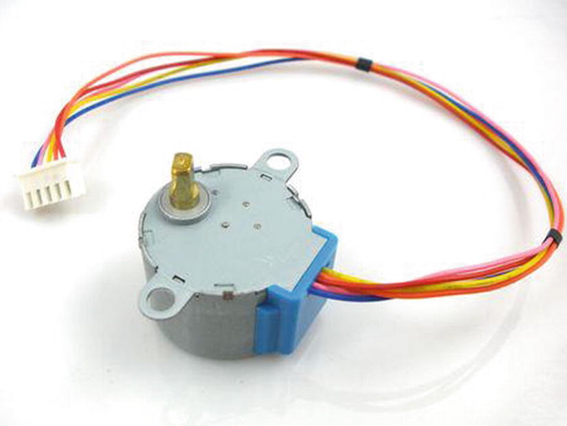
The 5V four-phase stepper motor, 28BYJ-48
Red connected to the +5V supply. This needs to be able to supply enough current to the motor, so it may need to be a different supply than the supply to the PIC. However, you should ensure all the 0V, or ground, of the supplies are connected together.
Orange connected to coil 1
Yellow connected to coil 2
Pink connected to coil 3
Blue connected to coil 4
The red lead supplies the 5V to all the coils. To energize the coils, the ground has to be connected to each coil to allow current to flow through them. If this is done in the correct sequence, the motor will turn in individual steps in either a clockwise or counterclockwise direction. The simplest way to switch the ground on to each coil is to use the ULN2004 driver I.C.. It has an array of seven Darlington NPN transistors. Each Darlington can sink up to 500mA, so they can easily cope with the current demanded from the coils of the stepper motor.
The Sequence to Rotate the Motor Clockwise
Coil Number | Coil Colour |
|---|---|
Coils 4 and 1 | Blue and orange |
Then coil 4 | Blue |
Then coils 3 and 4 | Pink and blue |
Then coil 3 | Pink |
Then coils 3 and 2 | Yellow and pink |
Then coil 2 | Yellow |
Then coils 1 and 2 | Orange and yellow |
Then coil 1 | Orange |
Note that clockwise is seen looking into the motor from the end of the shaft.
The Sequence for Rotating the Motor Counterclockwise
Coil Number | Coil Colour |
|---|---|
Coil 1 | Orange |
Then coils 1 and 2 | Orange and yellow |
Then coil 2 | Yellow |
Then coils 2 and 3 | Yellow and pink |
Then coil 3 | Pink |
Then coils 3 and 4 | Pink and blue |
Then coil 4 | Blue |
Then coils 4 and 1 | Blue and orange |
There should be a delay between changing from one step to the next step in the sequence. This delay must be long enough for the current in the coil to build up and so create the magnetic field that steps the motor round. However, the time constant of the coils is very short, so this delay can be short.
This stepper motor goes through 4096 of these individual steps to make one complete revolution. Therefore, each single step turns the stepper motor rotor through 0.08789 of a degree. As there are eight single steps in each sequence of steps, as shown in Tables 5-1 and 5-2, each sequence moves the motor through 0.70312 degrees. Therefore, it takes 360/0.70312 (i.e. 512 sequences of steps) to move the motor through 360 degrees or one complete revolution.
Using this information, you can determine how many steps, or sequences, are required to make the motor turn by any number of degrees.
The Basic Program for the Stepper Motor
This program sets the stepper motor to turn clockwise with a slow speed. The speed can be varied by pressing one of the three buttons connected to Bits 0, 1, and 2 of PORTA.
The motor goes through 400 sequences in the clockwise direction. Then it goes through 500 sequences in the counterclockwise direction. There is then a short delay before the motor repeats the process. The figure of 400 sequences means the motor will turn through 281O in the clockwise direction. Then it will turn through 352O in the counterclockwise direction.
This sets up a 16-bit memory location named ck, made up of two 8-bit registers cascaded together, that can store positive values from 0 to 65535.
The label orange is defined in line 12 as Bit3 of PORTB. In this instruction, you are setting the bit to a logic 1. This sends 5V from the PIC to the input of the ULN2004. This turns the Darlington transistor inside the driver I.C. on this transistor and then switches the ground onto the orange coil in the motor. This then allows the current to flow though that coil and so sets up the magnetic field around it.
These two instructions create a small delay between each of the steps. The shorter this delay is (i.e. the smaller the value in the variable speed), the faster the motor will rotate. However, the delay must be long enough to allow the current to build up in the coils and so create the magnetic field that drags the rotor to them.
Stepper motors have many applications where precise movements are required, and printers are the most common application of stepper motors. The actual stepper motor used in this book can be used in many hobbyist projects. I have used it to control a four-story model lift and a turntable in a model railway.
As an exercise, you explain what the following instruction, written on line 32, is doing:
Also, if the variable speed is loaded with 75, how long is the delay between switching the coils?
The Servo Motor
A servo motor is a motor that moves through a limited range of degrees. Typically it can move 90O in one direction and 90O in the opposite direction. It is normally controlled by sending a 50Hz frequency pulse train. The width of the pulse, the mark time, will vary from 1msec to 2msec. This variance of the pulse width will move the servo motor through its complete range of rotation. This movement can be described as going from -90O to +90O, or going from 0O to 180O in one direction. The relationship between the changes in degrees to the change in pulse width is linear. Therefore, with a pulse width of 1msec, the servo motor would move to -90; with a pulse width of 1.5msec, it would move to 0; and finally, with a pulse width of 2msec, it would move to +90. Of course, any value of pulse width between 1ms and 2ms would produce the corresponding degrees of rotation from the servo motor.
To control the movement of the servo motor, you need to be able to produce an accurate pulse width at the required frequency of 50Hz.
Using the CCPM to Produce the Pulse Train Signal
In this first example of controlling the servo motor, you will continue the theme of using the CCP module discussed in Chapter 4.
The first thing to do is produce the 50Hz square wave. Chapter 4 explains how you can go about creating a square wave.

This is the closest you can get to 155.25.
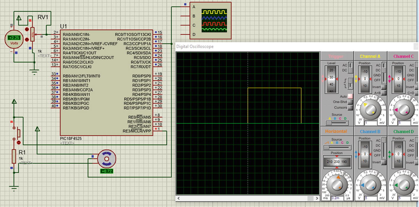
You should start off with the minimum pulse width of 1msec, which should correspond to turning the motor to -90O.

Since this has to be converted into a 10-bit binary number, the value is rounded down to 31. In 10-bit binary, the number is 0b0000011111. This means that both Bit5 and Bit4 of the CCP1CON register must be set to logic 1 and the CCPRl1 register must be loaded with 0b00000111.
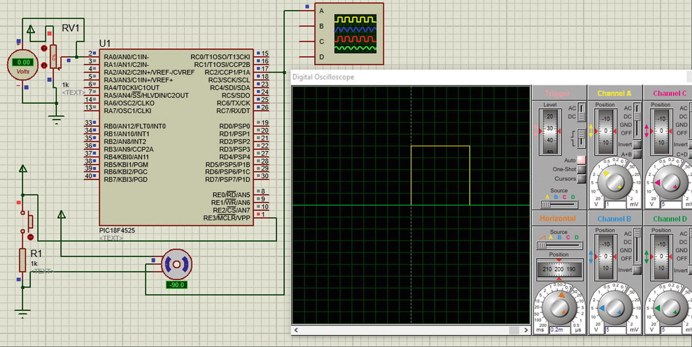
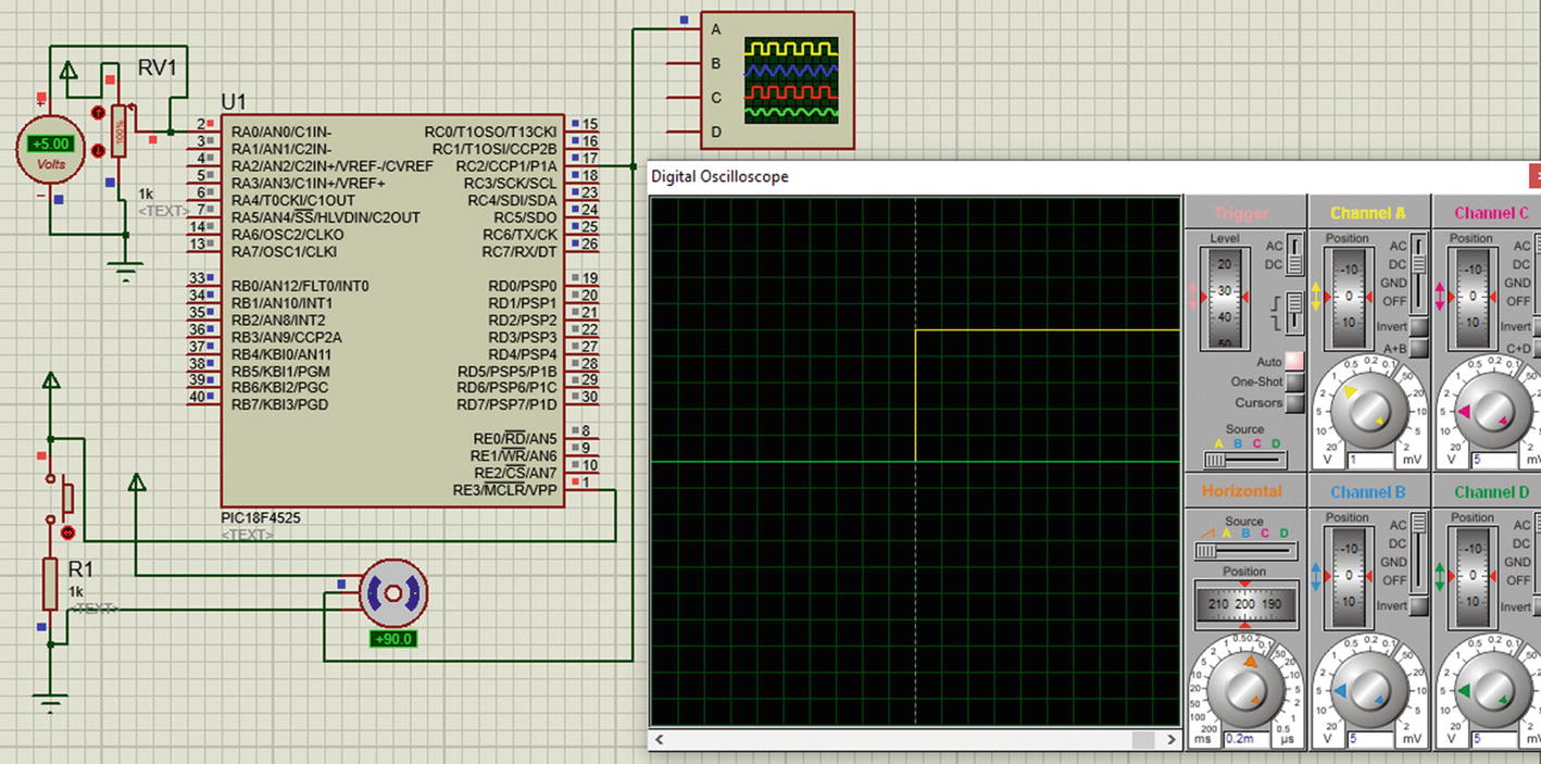
Using this concept, if you make the pulse width 1.5msec, the servo motor should be in the middle of its travel, which is 0O. To achieve a pulse width of 1.5msec, the number is 47 in decimal, which is 101111 in binary. This means Bit4 and Bit5 of the CCP1CON register must be set to logic 1 and 00001011 must be loaded into the CCPR1L register.
The result of the 1.5msec pulse
Controlling the Positions of the Servo Motor with a Variable Resistor
In this project, the position of the servo will be controlled via a potentiometer. This means the program will make use of one analog input, such as RA0, to take in the input from the potentiometer.
It will use the CCP1 output to output the 50Hz square wave and use the PWM module to vary the on pulse width from 1msec to 2msec and so control the position of the motor.
Controlling the Servo Motor with a Variable Voltage
The main working part of the program is the subroutine changeAngle. The main program simply calls this subroutine.
The width of the mark time of the 50Hz square wave is controlled via the value in the CCPR1L register. The value that the CCPR1L register needs to produce the minimum pulse of width of 1ms is 0b00000111, which is 7 in decimal. This value can be extended to 0b00001111, which is 15 in decimal, to produce the maximum pulse width of 2ms. This means that to start off with the minimum pulse width of 1ms, the CCPR1L must have the starting value of 7. Then, to get to the maximum pulse width of 2ms, the value in the CCPR1L should be increased by 8 to get to 15. This increase of 8 must come from the ADRESH. As the ADRESH changes from 0 to 255, in decimal, the potentiometer is moved from 0 to maximum. Dividing 8 by 255 gives the multiplying factor of 0.03137, hence the value used is 0.0314.
It is the instruction on line 11 that performs the function.
As an example of how this works, when the potentiometer is at 0V, the result of the ADC, stored in ADRESH, will be 0. Therefore, 7 + (0 x 0.0314) = 7. This creates a pulse width of 1ms.
When the potentiometer is at 5V, the ADRESH will go to 255. Therefore, you have 7 + (255 x 0.0314) = 7 + 8.007 = 15. The 0.007 is ignored as the instruction is making use of the “round” function. However, to use this “round” function you need to include the math.h header file, as is done in line 2 in Listing 5-2. This then will create the maximum pulse width of 2ms.
This is how the instruction on line 11, CCPR1L = (7+round(ADRESH * 0.0314));, works.
Again, I hope there is no need to give any further analysis of the instructions in the listing.
Improving The Servo Motor Program
The issue with this simple program to control the servo motor is the definition. The pulse width can only vary by 1ms. With the current program, it is the value stored in the CCPR1L register that controls the actual pulse width of the signal. A value of 7 will produce the 1ms pulse width and this can be increased up to a value of 15 to produce the maximum 2ms pulse width. This gives a resolution of 125μs. This variation from 1ms to 2ms or from a value of 7 to a value of 15 could produce a 180O movement in the motor. This then gives a resolution of 22.5O. Not good enough really. Also, it would not produce a smooth movement of the motor.
A good resolution would be 1O. This would mean dividing this 1ms variance into 180 jumps, giving a resolution of 5.5μs. This degree of resolution, and better, can be achieved by taking a more simplistic approach to creating the 50Hz square wave and the pulse width. This is what the following program does.
The Algorithm for the Improved Program
The basic concept is to turn an output on (i.e. set it high for at least 1ms and then keep it low for the remaining 19ms of the 50Hz period).
The timing of these two periods is controlled by simply using a counter to count the required clock pulses.
The program will use the basic timer0 to keep count of the clock pulses.
The program will use Bit0 of PORTB to output the control signal.
The program will use an analog signal from a variable voltage inputted to the PIC at bit0 of PORTA. This will be used to vary the pulse width from 1ms to 2ms. Note that when the pulse width is at 2ms, there will only be an 18ms time period for the output to stay low before starting the signal again.
The signal starts with timer0 at a value of 0 and with the output on bit0 of PORTB high. Then 1ms, or up to 2ms, later the output will go low. The output will stay low for the remaining 19ms or 18ms, after which the cycle will repeat.
- The oscillator will be the 8Mhz signal from the internal oscillator block. This means the clock frequency will be 2MHz. Timer0 will be set to a divide rate of 2, which means it will count at a rate of 1Mhz. This means that each count will have a time span of 1μs. This means that timer0 will count as follows:
1000 to create a 1ms pulse
2000 to create a 2ms pulse
20000 to create a full 20ms time period
This means that timer0 will have to be configured as a 16-bit counter, which can count up to 65535, which is more than enough for this purpose.
The ADC result will be stored into the ADRESH and ADRESL registers. You will use the left justification, which means the ADRESH will store the eight most significant bits, and the two least significant bits will be stored in Bit7 and Bit6 of the ADRESL register. You could keep the programming simple by just using the ADRESH register as the value for the analogue input. However, this would mean that the maximum value would be 255. This would result in a resolution of 0.7O, which is pretty good but you can do better than that.
Start timer0 counting from 0.
At the same time, send Bit0 of PORTB high.
Then create a variable for a waiting time from between 1ms to 2ms.
Then send the output low.
Then create a second variable for a waiting time of between 19ms to 18ms.
During that second wait time, read the analog input value and store it to be used to vary the pulse width.
Then, after the total 20ms has passed, repeat the cycle again.
The various time periods will be created using timer0.
The Improved Program to Control a Servo Motor
This instruction is part of the subroutine changeAngle . In this subroutine, you use the ADC to convert the variable voltage applied to Bit0 of PORTA into a 10-bit binary number. The PIC uses two 8-bit registers to store this 10-bit result since the PIC18f4525 only uses 8-bit registers. The two registers are called ADRESH and ADRESL. The letters ADRES stand for analog digital result, the H stands for high byte, and the L stands for low byte. This is because a 16-bit number, termed a word, can be split into two 8-bit numbers, termed a byte, which are termed the high byte for the upper 8 bits and the low byte for the lower 8 bits.
You are using left justification, which means the upper 8 bits of the ADC results are stored in the ADRESH register and the two remaining lower bits are stored in Bit7 and Bit6 of the ADRESL register, respectively.
You could use just the ADRESH register to obtain the value for the variable rotate, but this would reduce the resolution to 3.9μs or 0.7O for a 180O swing. However, if you used all 10 bits of the ADC result, you could achieve a resolution of 1μs or 0.18703O for a 180O swing.
To use all 10 bits, you must move a copy of both the ADRESH and the ADRESL into a 16-bit variable. The variable you will use is the rotate variable you created in line 10. However, this means that Bit7 of the ADRESH must be moved to Bit9 of the rotate variable. This is so that you can leave Bit0 and Bit1 of this 16-bit variable rotate for the two least significant bits of the result of the ADC conversion. This actually means that when you create the copy of the ADRESH in the variable rotate, you must first shift all the bits of the ADRESH two places to the left. This is done by including the C instruction << 2, as you do in line 16.
Now you need to add the 8 bits that have been stored in the ADRESL register. However, the two LSB bits of the ADC result were stored in Bits 7 and 6 of the ADRESL register. In those two positions, the bits will represent a value of 192, if they were both logic 1s, instead of 3, which is what they should represent because they would be Bits 1 and 0 of the ADC result. This means you must move the two bits from Bit7 and Bit6 to Bit1 and Bit0 before you add them to the variable rotate. This is what the instruction >>6 does. It shifts the bits six places to the right.
In this way you make sure that the variable rotate has the actual 10-bit binary number that is the full result of the ADC conversion in the correct position in the variable rotate.
However, there is still one issue to deal with. It is the issue that the 10-bit result can go to a maximum of 1023, not the 1000 that you want. This is because 10 bits have a value of 210 = 1024. Therefore, to reduce this value, and also to make sure you don’t create an increase in the pulse width greater than 1ms, you multiply the result of the addition by 0.95 before storing the result in the variable rotate. Note the use of brackets to split the instruction up into its different parts.
Setting Bit7 to a logic 1 turns the timer on.
Setting Bit6 to a logic 0 makes it a 16-bit register.
Setting Bit3 to a logic 0 allocates the prescaler, the divide rate to Timer0.
Setting Bits 2, 1, and 0 to a logic 0 gives a divide rate of 2.
Bits 5 and 4 are not really relevant here.
This instruction controls when the signal to the servo goes low. The if test asks if the value in timer0 is greater than or equal to the value stored in the variable rotate. You cannot simply ask, is timer equal to rotate? This will only be true for one instant in time, and the test might miss that instant.
If the test is true, the micro will set the output on Bit0 of PORTB to a logic 0. Note the term servoOut means Bit0 of PORTB as defined in line 8.
This traps the micro at this point in the program until the value in timer0 becomes greater than 18500. The value of 18500 in timer0 equates to 18500 x 1ms i.e. 18.5ms,
All the micro is asked to do while it is trapped here is call the subroutine changeAngle. In doing this, the micro will get the up-to-date position that the servo motor needs to take up. The call to the subroutine is at this point in the program because the micro is doing nothing while it waits for the 18.5ms period to complete.
It is important that the micro is not carrying out the instructions of the changeAngle subroutine when the 20ms time period comes to an end. This is important because if the micro was carrying out the changeAngle subroutine at this 20ms time period, then you might go over the 20ms period and so reduce the frequency of the pulse train. That is why the value for timer0 stipulated in the while test is 18500 not 20000. This is to ensure that the micro is not stuck inside the changeAngle subroutine during the last 1.5ms of the 20ms time period. You should appreciate that it will take at least 2.5μs for an ADC conversion to complete and there are other instructions in the changeAngle subroutine**.
This makes the micro do nothing until the final 1.5ms has finished. This then is the end of the full 20ms period of the 50Hz pulse train. At the end of this period, the micro is forced to go back to the start of the sequence, at line 39, using the label begin as stated on line 43.
I downloaded the program using my prototype board to a practical servo motor. The movement of the motor was very smooth and the frequency of the pulse train was very stable at 50Hz. The pulse width did vary smoothly from 1ms to 2ms. Therefore I am much happier with this improved program than the first program that used the CCP module.
** To understand more of the ADC conversion routine, please read my first book, C Programming for PIC Microcontrollers.
Summary
In this chapter, you learned how to control two very useful types of motors, the stepper motor and the servo motor.
You also studied how the CCP module and the basic timer module can be used to control a servo motor.
You looked at how you can use some basic math tools in C programs and how to manipulate the bits of data in 8-bit registers to correctly align them in a 16-bit register.
Servo motors are widely used in industries with robotics, actuators, etc. and with hobbyist in remote cars, boats, and airplanes.
I hope this chapter has given you a fundamental appreciation of the two motors and the basis on which to use them in your own exciting projects.
In the next chapter, you will look at using a very exciting and useful aspect of all microcontrollers: the use of interrupts. You will also look at using the compare and capture aspect of the CCP module.
Solution to the Exercise
This means Bit7 is a logic 1, which simply turns timer 0 on.
Also, Bit6 is a logic 1, which means the timer is an 8-bit timer.
Bit3 is a logic 0, which means the prescaler or divider is applied to timer0.
Osc = 8Mhz as set by the OSCCON register.
The clock runs at a quarter of the oscillator, therefore it runs at 2Mhz.
Time0 divides this by 128, therefore timer1 runs at 15.625kHz, so one count takes 64μS.
Loading the variable speed with 75 makes the micro wait until Timer0 has counted to a value of 75. As it takes Timer0 64μs to count once, it will take 75x64E-6 i.e. 4.8ms. This means the delay between switching the coils will be around 4.8ms. It will take some time for the micro to complete the instructions in the delay and this will add a bit more to the delay but this would be very small, in the order of a couple of microseconds.